JP4600552B2 - Outline conversion method, image compression method using the same, outline conversion apparatus, and outline conversion program - Google Patents
Outline conversion method, image compression method using the same, outline conversion apparatus, and outline conversion program Download PDFInfo
- Publication number
- JP4600552B2 JP4600552B2 JP2008236771A JP2008236771A JP4600552B2 JP 4600552 B2 JP4600552 B2 JP 4600552B2 JP 2008236771 A JP2008236771 A JP 2008236771A JP 2008236771 A JP2008236771 A JP 2008236771A JP 4600552 B2 JP4600552 B2 JP 4600552B2
- Authority
- JP
- Japan
- Prior art keywords
- straight line
- contour
- outline
- adjacent
- image data
- Prior art date
- Legal status (The legal status is an assumption and is not a legal conclusion. Google has not performed a legal analysis and makes no representation as to the accuracy of the status listed.)
- Expired - Fee Related
Links
Images


Classifications
-
- G—PHYSICS
- G06—COMPUTING OR CALCULATING; COUNTING
- G06T—IMAGE DATA PROCESSING OR GENERATION, IN GENERAL
- G06T7/00—Image analysis
- G06T7/10—Segmentation; Edge detection
- G06T7/12—Edge-based segmentation
-
- G—PHYSICS
- G06—COMPUTING OR CALCULATING; COUNTING
- G06V—IMAGE OR VIDEO RECOGNITION OR UNDERSTANDING
- G06V30/00—Character recognition; Recognising digital ink; Document-oriented image-based pattern recognition
- G06V30/10—Character recognition
- G06V30/18—Extraction of features or characteristics of the image
- G06V30/182—Extraction of features or characteristics of the image by coding the contour of the pattern
-
- G—PHYSICS
- G06—COMPUTING OR CALCULATING; COUNTING
- G06V—IMAGE OR VIDEO RECOGNITION OR UNDERSTANDING
- G06V30/00—Character recognition; Recognising digital ink; Document-oriented image-based pattern recognition
- G06V30/10—Character recognition
Landscapes
- Engineering & Computer Science (AREA)
- Computer Vision & Pattern Recognition (AREA)
- Physics & Mathematics (AREA)
- General Physics & Mathematics (AREA)
- Theoretical Computer Science (AREA)
- Multimedia (AREA)
- Compression Of Band Width Or Redundancy In Fax (AREA)
- Image Processing (AREA)
- Image Generation (AREA)
Description
本発明は、画像データからアウトラインデータを生成するアウトライン化方法およびそれを用いた画像圧縮方法、アウトライン化装置、ならびにアウトライン化プログラムに関する。 The present invention relates to an outline generation method for generating outline data from image data, an image compression method using the outline data, an outline conversion apparatus, and an outline conversion program.
画像データに含まれる文字部分をアウトライン化する技術が、従来から種々提案されている。 Conventionally, various techniques for creating an outline of a character portion included in image data have been proposed.
たとえば、特許文献1(特開2005−346137号公報)には、用紙に印刷された画像をスキャンすることによりアウトライン化データを作成する技術が開示されている。 For example, Japanese Patent Laid-Open No. 2005-346137 discloses a technique for creating outline data by scanning an image printed on paper.
なお、特許文献1では、スキャン時に、文字の輪郭上で画素の欠落等のノイズが発生した場合には、アウトライン化後に除去される。
従来のアウトライン化データの生成の際には、1文字ごとに、2値化データに対して輪郭画素が抽出され、当該輪郭画素に基づいてその外郭が直線近似され、そして、直線近似されたデータが曲線近似されていた。 At the time of generating the conventional outline data, contour pixels are extracted from the binarized data for each character, the outline is linearly approximated based on the contour pixels, and the linearly approximated data The curve was approximated.
たとえば、図17に示される画素P1〜P4の4点が輪郭画素として抽出された場合、図18の直線L0で示される線が求められ、一定の条件が満たされれば、図18中に破線で示された、画素P1〜P4を結ぶ線の代わりに当該直線L0が外郭として直線近似データが作成されていた。なお、直線L0は、たとえば、画素P1〜P4の各点から等しい距離にある直線である。一定の条件とは、たとえば、画素P1〜P4の各点から直線L0の距離の和が予め定められた閾値以下となることである。 For example, when four points of pixels P1 to P4 shown in FIG. 17 are extracted as contour pixels, a line indicated by a straight line L0 in FIG. 18 is obtained, and if a certain condition is satisfied, a broken line in FIG. Instead of the line connecting the pixels P <b> 1 to P <b> 4 shown, the straight line approximate data is created with the straight line L <b> 0 as the outline. The straight line L0 is a straight line that is at an equal distance from each point of the pixels P1 to P4, for example. The certain condition is, for example, that the sum of the distances of the straight line L0 from each point of the pixels P1 to P4 is equal to or less than a predetermined threshold value.
しかしながら、図17および図18を参照して説明したような態様で文字の外郭が直線近似された場合、アウトライン化データにおいて、本来水平または垂直の線で表されるべきところが、端部の画素の欠けによって、本来表されるべき向きに対して多少斜めに表される事態が生じる。図19を参照して、具体的に説明する。 However, when the outline of the character is linearly approximated in the manner described with reference to FIGS. 17 and 18, what should be represented by a horizontal or vertical line in the outline data is that of the end pixel. Due to the chipping, a situation occurs that is slightly inclined with respect to the direction to be originally represented. A specific description will be given with reference to FIG.
図19(A)は、アルファベット「E」の2値化画像の一例であり、図19(B)は、図19(A)の2値化画像をアウトライン化したデータの一例である。 FIG. 19A is an example of a binarized image of the alphabet “E”, and FIG. 19B is an example of data obtained by outlining the binarized image of FIG. 19A.
図19(B)の左上の破線の円内の、下側の外郭を構成する線LX1は、図19(A)内の対応箇所と対比することにより理解されるように、本来は、2値化画像のデータのままで水平とされるべきところ、図17および図18を参照して説明したような直線近似が行なわれてしまったために、水平方向とは交わる方向に(右肩下がりに)伸びている。 The line LX1 constituting the lower outline in the upper left broken circle in FIG. 19B is originally binary as understood by comparing with the corresponding portion in FIG. 19A. Since the straight line approximation as described with reference to FIG. 17 and FIG. 18 has been performed where it should be horizontal with the converted image data as it is, it intersects with the horizontal direction (in a downward direction). It is growing.
また、図19(B)の下方の破線の円内の、上側の外郭を構成する線LX2も、同様に、図19(A)内の対応箇所と対比して、本来は2値化画像のデータのままで水平とされるべきところが、水平方向とは交わる方向に(右肩上がりに)伸びている。 Similarly, the line LX2 constituting the upper outline in the broken-line circle at the bottom of FIG. 19B is also compared with the corresponding portion in FIG. Where the data should be leveled, it extends in a direction that crosses the horizontal direction (upwardly).
つまり、従来のアウトライン化では、本来その外郭が水平または垂直にされるべきところであって、2値化画像では水平または垂直に表現されているにもかかわらず、画像処理を行なうことにより却って水平または垂直方向に対して多少角度をもった方向とされる場合があった。アウトライン化された画像の外郭において、水平方向または垂直方向とされるべきところがこれらの各方向に対して角度を持つ方向とされると、目立つとともに見る人に違和感を与える。 That is, in the conventional outline conversion, the outline should be horizontal or vertical, and even though the binary image is expressed as horizontal or vertical, it can be displayed horizontally or horizontally by performing image processing. In some cases, the direction is slightly inclined with respect to the vertical direction. In the outline of the outline image, if the place that should be set in the horizontal direction or the vertical direction is set to have an angle with respect to each of these directions, the outline is noticeable and the viewer feels uncomfortable.
本発明は、かかる実情に鑑み考え出されたものであり、その目的は、2値化画像のアウトライン化において、2値化画像に含まれる外郭の中で適切な部分については残しつつ、滑らかな曲線等を得るための画像処理を実行することができる、アウトライン化方法およびそれを用いた画像圧縮方法、アウトライン化装置、ならびにアウトライン化プログラムを提供することである。 The present invention has been conceived in view of such a situation, and the object thereof is to smooth out the outline of the binarized image while leaving an appropriate portion in the outline included in the binarized image. To provide an outline method, an image compression method, an outline device, and an outline program that can execute image processing for obtaining a curve or the like.
本発明に従ったアウトライン化方法は、2値化された画像データに対して、特定のパターンからパターンマッチングにより抽出された輪郭画素を抽出する輪郭画素抽出ステップと、前記輪郭画素に基づいて、前記画像データの輪郭を直線近似する直線近似ステップとを備え、前記直線近似ステップは、隣接する輪郭画素間の距離を算出する算出ステップと、第1の輪郭画素と前記第1の輪郭画素に隣接する第2の輪郭画素とを結ぶ直線である第1の直線の長さと、隣接する輪郭画素間を結んだ直線であって前記第1の直線に隣接する直線を含む直線の長さとの比較結果に基づいて、前記第1の直線を、前記画像データの輪郭にするか否かを決定する決定ステップとを含むことを特徴とする。 The outline conversion method according to the present invention includes: a contour pixel extraction step for extracting a contour pixel extracted from a specific pattern by pattern matching for binarized image data; A linear approximation step for linearly approximating the contour of the image data, wherein the linear approximation step is adjacent to the first contour pixel and the first contour pixel; A comparison result between the length of the first straight line that connects the second contour pixels and the length of the straight line that connects the adjacent contour pixels and includes the straight line adjacent to the first straight line. And a determining step for determining whether or not the first straight line is to be an outline of the image data.
また、本発明のアウトライン化方法は、前記決定ステップでは、前記第1の直線が、前記第1の直線に隣接する直線を含む直線の長さに基づいて算出される長さよりも長い場合に、前記画像データの輪郭とされることが決定されることが好ましい。 In the outline generation method of the present invention, in the determining step, when the first straight line is longer than a length calculated based on a length of a straight line including a straight line adjacent to the first straight line, It is preferable that the contour of the image data is determined.
また、本発明のアウトライン化方法は、前記決定ステップでは、前記第1の直線が、前記第1の直線に隣接する第2の直線に対して所定の倍率以上長く、かつ、前記第2の直線に隣接する第3の直線に対して所定の倍率以上長い場合に、前記画像データの輪郭とされることが好ましい。 In the outline forming method of the present invention, in the determining step, the first straight line is longer than a second magnification by a predetermined magnification with respect to the second straight line adjacent to the first straight line, and the second straight line. It is preferable that the image data has an outline when it is longer than a predetermined magnification by a third straight line adjacent to the image.
また、本発明のアウトライン化方法では、前記所定の倍率は2〜4倍であることが好ましい。 In the outline forming method of the present invention, the predetermined magnification is preferably 2 to 4 times.
また、本発明のアウトライン化方法では、前記決定ステップは、前記第1の直線の長さが、前記第1の直線の一方側に隣接する前記第2の直線および前記第3の直線の長さに対して前記所定の倍率未満であった場合に、隣接する輪郭画素間を結んだ直線であって、前記第1の直線の他方側に隣接する第4の直線に対して前記所定の倍率以上長い場合には、前記第1の直線を前記画像データの輪郭とすると決定することが好ましい。 Further, in the outline conversion method of the present invention, the determining step includes the lengths of the second straight line and the third straight line that are adjacent to one side of the first straight line. Is a straight line connecting adjacent contour pixels and is equal to or greater than the predetermined magnification with respect to a fourth straight line adjacent to the other side of the first straight line. If it is long, it is preferable to determine that the first straight line is the contour of the image data.
本発明に従った画像圧縮方法は、上記したアウトライン化方法によりアウトライン化された画像データを少なくとも含む画像データを圧縮するステップを備えることを特徴とする。 An image compression method according to the present invention includes a step of compressing image data including at least the image data outlined by the outline conversion method described above.
本発明に従ったアウトライン化装置は、2値化された画像データに対して、特定のパターンからパターンマッチングにより抽出された輪郭画素を抽出する抽出部と、前記輪郭画素に基づいて、前記画像データの輪郭を直線近似する直線近似部とを備え、前記直線近似部は、隣接する輪郭画素間の距離を算出する算出部と、第1の輪郭画素と前記第1の輪郭画素に隣接する第2の輪郭画素とを結ぶ直線である第1の直線の長さと、隣接する輪郭画素間を結んだ直線であって前記第1の直線に隣接する直線を含む直線の長さとの比較結果に基づいて、前記第1の直線を、前記画像データの輪郭にするか否かを決定する決定部とを含むことを特徴とする。 An outliner according to the present invention includes: an extraction unit that extracts a contour pixel extracted from a specific pattern by pattern matching for binarized image data; and the image data based on the contour pixel. A linear approximation unit that linearly approximates the contour of the first contour pixel, the linear approximation unit calculating a distance between adjacent contour pixels, a first contour pixel, and a second contour pixel adjacent to the first contour pixel. Based on the comparison result between the length of the first straight line that is a straight line connecting the contour pixels and the length of the straight line that connects the adjacent contour pixels and includes the straight line adjacent to the first straight line And a determining unit that determines whether or not the first straight line is to be an outline of the image data.
本発明に従ったアウトライン化プログラムは、画像処理装置に、画像データからアウトラインデータを生成させる、コンピュータ読取可能なアウトライン化プログラムであって、前記画像処理装置に、2値化された画像データに対して、特定のパターンからパターンマッチングにより抽出された輪郭画素を抽出する輪郭画素抽出ステップと、前記輪郭画素に基づいて、前記画像データの輪郭を直線近似する直線近似ステップとを実行させ、前記直線近似ステップは、隣接する輪郭画素間の距離を算出する算出ステップと、第1の輪郭画素と前記第1の輪郭画素に隣接する第2の輪郭画素とを結ぶ直線である第1の直線の長さと、隣接する輪郭画素間を結んだ直線であって前記第1の直線に隣接する直線を含む直線の長さとの比較結果に基づいて、前記第1の直線を、前記画像データの輪郭にするか否かを決定する決定ステップとを含むことを特徴とする。 An outline conversion program according to the present invention is a computer-readable outline conversion program for causing an image processing apparatus to generate outline data from image data. The image processing apparatus performs binarization on image data. A contour pixel extraction step for extracting a contour pixel extracted by pattern matching from a specific pattern, and a linear approximation step for linearly approximating the contour of the image data based on the contour pixel, thereby performing the linear approximation A step of calculating a distance between adjacent contour pixels, and a length of a first straight line that is a straight line connecting the first contour pixel and the second contour pixel adjacent to the first contour pixel; , Based on a comparison result with the length of a straight line connecting adjacent contour pixels and including a straight line adjacent to the first straight line , The first straight line, characterized in that it comprises a determining step of determining whether the contour of the image data.
本発明によれば、画像のアウトライン化において、2値化された画像データから輪郭画素を抽出した際に、隣接する2つの輪郭画素を結ぶことによって生じる直線の長さに応じて、当該直線が、2値化画像が直線で近似された際にそのまま残されるか否かが決定される。 According to the present invention, when the outline pixel is extracted from the binarized image data in the outline of the image, the straight line is determined according to the length of the straight line generated by connecting two adjacent outline pixels. Whether or not the binarized image is left as it is when it is approximated by a straight line is determined.
これにより、アウトライン画像の生成において直線近似された画像では、上記のような直線の長さによっては当該直線がそのまま残される場合がある。 Thereby, in the image approximated by a straight line in the generation of the outline image, the straight line may remain as it is depending on the length of the straight line as described above.
したがって、2値化画像のアウトライン化において、2値化画像の外郭を構成する直線の中で、適切な部分については残しつつ、他の部分については滑らかな曲線等を得るための画像処理が実行される。よって、2値化画像に含まれる外郭の中で適切な部分については残しつつ、上記画像処理により滑らかな曲線等を含むアウトライン画像を生成できるようにすることができる。 Therefore, in the outline of the binarized image, image processing is performed to obtain a smooth curve or the like for the other part while leaving the appropriate part in the straight line constituting the outline of the binarized image. Is done. Accordingly, it is possible to generate an outline image including a smooth curve or the like by the image processing while leaving an appropriate portion in the outline included in the binarized image.
以下、本発明の画像処理装置の実施の形態について、図面を参照して説明する。
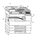
図1は、本発明の画像処理装置の一実施の形態であるMFP(Multi Function Peripherals)1の外観を示す図である。
Embodiments of an image processing apparatus according to the present invention will be described below with reference to the drawings.
FIG. 1 is a diagram showing an appearance of an MFP (Multi Function Peripherals) 1 which is an embodiment of an image processing apparatus of the present invention.
MFP1は、各種の処理に対する操作指示、ならびに、文字および数字のデータの入力を受付ける操作パネル15を備えている。操作パネル15には、電源キー等の、ユーザが操作するための複数のキーが設けられている。
The
また、MFP1は、原稿を光電的に読取って画像データを得るスキャナ11、画像データに基づいて記録シート上に画像を印刷する印刷装置(エンジン)12、印刷装置12に記録シートを供給する給紙部18、印刷装置12によって画像を印刷された記録シートが排出されるトレイ19、および、後述するCPU(central processing unit)10A等を収納する制御部10を備えている。
The
スキャナ11は、写真、文字、絵などの画像情報を原稿から光電的に読取って画像データを取得する。取得された画像データは、適宜処理を施された後、ネットワークを介して送信される電子メールの添付ファイル用のデータとして利用されたり、電話回線等を介して他の機器に送信されたり、印刷装置12に送られて印刷に供されたりする。
The
図2は、図1のMFP1のハードウェア構成を示す図である。
図2を参照して、MFP1は、上述した構成要素の他に、入力画像処理部10B、記憶部10C、CPU10A、ネットワークI/F(インターフェイス)10E、出力画像処理部10D、および通信部10Fを含む。
FIG. 2 is a diagram illustrating a hardware configuration of the
Referring to FIG. 2,
MFP1では、スキャナ11で取得された画像データは、入力画像処理部10Bに送られる。
In the
入力画像処理部10Bは、入力された画像の色変換、色補正、解像度変換、および領域判別等の処理を実行する。入力画像処理部10Bにおいて処理されたデータは、記憶部10Cで保存される。記憶部10Cは、DRAM(Dynamic Random Access Memory)等のメモリ、および、磁気メモリの一例であるハードディスクを備えたハードディスクドライブ(HDD)を含む。なお、MFP1では、入力画像処理部10Bは、たとえば、CPU10Aが記憶部10C(またはMFP1に対して着脱可能な記録媒体)に記録されたプログラムを実行することによって実現されても良いし、MFP1に実装される1つのまたは複数のASIC(Application Specific Integrated Circuit)によって実現されても良い。
The input image processing unit 10B executes processes such as color conversion, color correction, resolution conversion, and area determination of the input image. Data processed in the input image processing unit 10B is stored in the storage unit 10C. The storage unit 10C includes a memory such as a dynamic random access memory (DRAM) and a hard disk drive (HDD) including a hard disk as an example of a magnetic memory. In
CPU10Aは、MFP1の全体的な制御、操作キー(表示パネル15の表示部に表示されるキー等)に対する操作の検出、操作パネル15の表示、入力されたデータの画像ファイルへの変更等の処理を実行する。
The
ネットワークI/F10Eは、電子メール等をネットワークへ送信するI/F部分であり、プロトコルの作成等を行なう。
The network I /
出力画像処理部10Dは、写真画像の粒状性を向上させるためのスクリーン制御、文字エッジの滑らかさを向上させるためのスムージング処理、PWM(Pulse Width Modulation)制御等を行なう。
The output
印刷装置12は、出力画像処理部で生成されたデータを用紙に印刷する。
通信部10Fは、モデムおよびNCU(Network Control Unit)を含み、ファクシミリの送受信の変復調、ファクシミリの通信プロトコルの生成、電話回線への接続等を行なう。
The
The
操作パネル15は、操作キーと表示部とを含む。表示部は、たとえば液晶のタッチパネルによって構成される。操作キーは、たとえば当該液晶のタッチパネルに表示されるタッチキーによって構成される。
図3は、図2の入力画像処理部10Bの詳細な構成を示す図である。
図3を参照して、入力画像処理部10Bは、前処理部210と、領域判別部220と、2値化処理部231と、輪郭画像抽出部232と、直線ベクトル近似処理部233と、曲線ベクトル近似処理部234と、文字領域圧縮部235と、写真・背景領域圧縮部236と、圧縮データ合成部240とを含む。
FIG. 3 is a diagram showing a detailed configuration of the input image processing unit 10B of FIG.
Referring to FIG. 3, the input image processing unit 10B includes a
スキャナ11は、原稿をスキャンすることによって画像データを生成すると、その画像データを前処理部210に出力する。
When the
前処理部210では、画像データに対して、画像形式の変換、解像度の変換、および下地処理等の処理が行なわれる。これらの処理を施された画像データは、領域判別部220に送られる。
The
領域判別部220では、まず、写真、背景、文字等の領域判別を行なうことにより、画像データを、文字領域と文字以外の領域(写真・背景領域)とに分ける。
The
そして、領域判別部220は、文字領域の画像データを2値化処理部231に送り、写真・背景領域の画像データを写真・背景領域圧縮部236に送る。
Then, the
なお、領域判別部220は、写真・背景領域の画像データについては、入力されたフルカラー24bitの画像データから8bitの明度画像を生成し、当該明度画像にスムージング処理を行ない、ノイズを除去する。そして、生成されたスムージング画像を、ラベリング処理することにより、前処理部210から送られた画像データに含まれる複数の写真・背景領域の位置を検出する。
Note that the
2値化処理部231は、入力された文字領域の画像データに対し、2値化処理を行ない、文字と背景を分離する。2値化された画像データは、輪郭画素抽出部232へ送られ、輪郭画素抽出部232と直線ベクトル近似処理部233と曲線ベクトル近似処理部234とにおいて行なわれるアウトラインデータ変換処理に供される。
The
輪郭画素抽出部232では、2値化された文字画像を走査して、パターンマッチングにより、輪郭画素が抽出される。
The contour
図5(A)には、パターンマッチングに用いる輪郭画素抽出パターンの一例が示されており、図5(B)には、2値化された文字画像の一部が拡大されて示されている。2値化らされた文字画像を(たとえば、4画素単位で)走査し、図5(A)にいずれかのパターンに合致する画素が輪郭画素として抽出される。このようなパターンマッチングによって、一例として、図5(B)に示されるように、一点鎖線で囲まれた画素が、輪郭画素として抽出される。 FIG. 5A shows an example of a contour pixel extraction pattern used for pattern matching, and FIG. 5B shows an enlarged part of a binarized character image. . The binarized character image is scanned (for example, in units of 4 pixels), and pixels that match any of the patterns in FIG. 5A are extracted as contour pixels. By such pattern matching, as an example, as shown in FIG. 5B, pixels surrounded by an alternate long and short dash line are extracted as contour pixels.
輪郭画素抽出部232において輪郭画素を抽出された後、画像データは、直線ベクトル近似処理部233に送られる。直線ベクトル近似処理部233では、輪郭画素抽出部232において抽出された輪郭画素について、近隣の輪郭画素が1つのベクトルとして表現されることにより、文字画像の輪郭が直線近似される。直線ベクトル近似処理部233において輪郭を直線近似された文字画像のデータは、曲線ベクトル近似処理部234に送られる。
After the contour pixels are extracted by the contour
曲線ベクトル近似処理部234では、直線ベクトル近似処理部233において生成された、文字画像の輪郭の直線ベクトルに対し、曲線条件に応じて適宜制御点が設定され、当該制御点に基づいて、文字画像の輪郭の曲線近似がなされる。
In the curve vector
本実施の形態のMFP1では、曲線条件に応じた制御点の設定を、特徴の1つとする。なお、直線ベクトル近似処理部233における輪郭画素に基づいた直線ベクトルの設定、および、曲線ベクトル近似処理部234における制御点に基づいて曲線近似については、周知の技術を採用することができるため、ここでは説明を繰返さない。
In
文字領域圧縮部235では、文字領域に適したデータの圧縮が行なわれる。また、写真・背景領域圧縮部236では、写真・背景領域に適したデータの圧縮が行なわれる。文字領域の画像データは、ベクトルデータ(位置情報)になっているため、FLATE圧縮方式のような可逆性の圧縮方式が好適と考えられる。写真・背景領域は、画質の維持よりもファイルサイズが小さくなることを優先させる場合、たとえば圧縮率を高く設定したJPEG圧縮方式のような非可逆性の圧縮方式が好適と考えられる。
In the character
圧縮データ合成部240は、文字領域圧縮部235で圧縮された文字領域の画像データと写真・背景領域圧縮部236において圧縮された写真・背景領域の画像データとを合成して、PDF(Portable Document Format)ファイルを生成して、記憶部10Cへ出力する。
The compressed
MFP1では、文字には文字用に好適な圧縮を、写真には写真用に好適な圧縮を施し、最終的には、両者をレイヤとして重ね合わせて1つのPDFファイルフォーマットのデータを生成する。これにより、画像データを、単一の圧縮方式(例えば、JPEG圧縮)で圧縮するよりもサイズの小さいファイルに変換することができる。
In the
以上説明したように、MFP1では、スキャナ11で読込まれた画像は、入力画像処理部10Bで処理されることにより、文字領域と写真・背景領域とで異なる方式で圧縮処理されたPDFファイルに変換されて、記憶部10Cに保存される。
As described above, in the
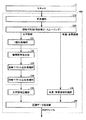
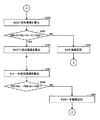
図4は、このようなPDFファイルへの画像データの変換が行なわれる際の、輪郭画素抽出部232と直線ベクトル近似処理部233と曲線ベクトル近似処理部234において実行される処理(アウトライン変換処理)のフローチャートである。以下、アウトライン変換処理について、詳細に説明する。
FIG. 4 shows processing (outline conversion processing) executed by the contour
図4を参照して、輪郭画素抽出部232に2値化された画像データが入力されると、輪郭画像抽出部232は、ステップS10で、文字領域の画像データを、1文字単位に分離して、ステップS20へ処理を進める。
Referring to FIG. 4, when binarized image data is input to contour
ステップS20では、輪郭画素抽出部232は、ステップS10において分離されたすべての文字について、ステップS30〜ステップS80の処理の対象とされたか否かを判断し、対象とされたと判断するとアウトライン変換処理を終了させ、まだ対象とされていない文字があると判断するとステップS30へ処理を進める。
In step S20, the contour
ステップS30では、輪郭画素抽出部232は、ステップS10で分離された各文字の中でまだステップS30〜ステップS80の処理対象とされていない文字を処理対象とし、当該処理対象の文字について、パターンマッチングにより輪郭画素を抽出して、ステップS40へ処理を進める。
In step S30, the contour
ステップS30の処理により、図5を参照して上述したように、図5(B)において一点鎖線で囲まれた画素が、輪郭画素として抽出される。 By the processing in step S30, as described above with reference to FIG. 5, the pixels surrounded by the alternate long and short dash line in FIG. 5B are extracted as contour pixels.
ステップS40では、輪郭画素抽出部232は、処理対象の文字においてすべての輪郭画素が抽出されたか否かを判断し、抽出されたと判断するとステップS50へ処理を進める。
In step S40, the contour
ステップS50では、直線ベクトル近似処理部233が、上述したように、輪郭画素抽出部232によって抽出された輪郭画素に基づいて、複数の輪郭画素を所定のアルゴリズムに従って直線近似し、近似された直線を順に直線ベクトルとして連結してゆくことにより、処理対象となっている文字の輪郭を直線ベクトルで近似して、ステップS60へ処理を進める。なお、直線近似アルゴリズムとしては、公知のいずれの方法も適用可能である。
In step S50, as described above, the straight line vector
ステップS50における直線ベクトル近似処理の内容については、後述する。
ステップS60では、直線ベクトル近似処理部233は、処理対象となっている文字について抽出されたすべての輪郭画素について直線ベクトル近似が終了したか否かを判断し、まだ終了していないと判断するとステップS50へ処理を戻し、終了したと判断するとステップS70へ処理を進める。
The content of the straight line vector approximation process in step S50 will be described later.
In step S60, the straight line vector
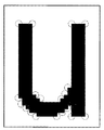
図6は、「u」が処理対象の文字とされている場合に、当該文字の画像に対して抽出された輪郭画素を模式的に示す図である。 FIG. 6 is a diagram schematically illustrating contour pixels extracted for an image of a character when “u” is a character to be processed.
図6では、「u」の文字画像に対して抽出された輪郭画素が、点線の円を付されて示されている。そして、これらの輪郭画素に基づいて当該文字画像が直線ベクトル近似されたものを、図7に示す。 In FIG. 6, contour pixels extracted from the character image “u” are shown with dotted circles. FIG. 7 shows the character image obtained by linear vector approximation based on these contour pixels.
図7では、直線ベクトルが、「●」という記号で連結されている状態が示されている。
ステップS70では、図7に示したような直線ベクトル近似された処理対象の文字について、各直線ベクトル上に適宜制御点を設定し、当該制御点を用いて、処理対象の輪郭を曲線ベクトル近似して、処理をステップS80へ進める。
FIG. 7 shows a state in which straight line vectors are connected by a symbol “●”.
In step S70, control characters are appropriately set on each straight line vector for the character to be processed that is approximated by a straight line vector as shown in FIG. 7, and the contour of the processing target is approximated by a curve vector using the control point. Then, the process proceeds to step S80.
ステップS80では、曲線ベクトル近似処理部234は、処理対象の文字画像についてステップS50で生成された直線ベクトルのすべてについて曲線ベクトル近似が終了したか否かを判断し、終了していないと判断するとステップS70へ処理を戻し、終了したと判断するとステップS20へ処理を戻す。
In step S80, the curve vector
ステップS70の処理によりすべての直線ベクトルについて曲線ベクトル近似がなされると、図7に示した直線ベクトルによって表現された文字画像が、図8に示すように、曲線を含む文字画像へと変換される。 When curve vector approximation is performed for all the straight line vectors by the process of step S70, the character image represented by the straight line vector shown in FIG. 7 is converted into a character image including a curve as shown in FIG. .
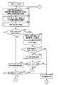
図9から図11は、図4のステップS50の直線ベクトル近似処理のサブルーチンのフローチャートである。 9 to 11 are flowcharts of the subroutine of the straight line vector approximation process in step S50 of FIG.
まず図9を参照して、直線ベクトル近似処理では、処理対象とされている文字画像について抽出された輪郭画素の中から、1つの処理対象の輪郭画素と、当該処理対象の輪郭画素にある方向に隣接する輪郭画素とが選択されて、処理がステップS503へ進められる。以下の説明では、便宜上、処理対象の輪郭画素を「輪郭画素A」とし、上記のある方向を「第1の方向」とし、また、処理対象の輪郭画素に隣接する輪郭画素を「輪郭画素B」とする。 First, referring to FIG. 9, in the straight line vector approximation process, one outline pixel to be processed from the outline pixels extracted for the character image to be processed and the direction in the outline pixel to be processed Is selected, and the process advances to step S503. In the following description, for convenience, the contour pixel to be processed is referred to as “contour pixel A”, the certain direction is referred to as “first direction”, and the contour pixel adjacent to the contour pixel to be processed is referred to as “contour pixel B”. "
図12は、処理対象とされている文字画像の2値化画像から抽出された複数の輪郭画素の一部について、その配列の一部を示す図である。図12では、反時計方向(第1の方向)に、点X、点Y、点Z、点A、点B、点C、点D、点Eが並んでいる。 FIG. 12 is a diagram illustrating a part of an array of a plurality of contour pixels extracted from a binarized image of a character image to be processed. In FIG. 12, point X, point Y, point Z, point A, point B, point C, point D, and point E are arranged in the counterclockwise direction (first direction).
そして、図12中の点Aと点Bが、それぞれ上記したステップS501において選択された輪郭画素Aと輪郭画素Bとする。 Then, point A and point B in FIG. 12 are the contour pixel A and the contour pixel B selected in step S501 described above, respectively.
さらに図9を参照して、ステップS503では、処理対象の輪郭画素Aについて、第1の方向に隣接する輪郭画素Bに加え、さらに当該輪郭画素Bと第1の方向に隣接する輪郭画素(図12の点C)と、さらに輪郭画素Cと第1の方向に隣接する輪郭画素(図12の点D)とが選択されて、ステップS505へ処理が進められる。 Further, referring to FIG. 9, in step S503, in addition to the contour pixel B adjacent in the first direction, the contour pixel adjacent to the contour pixel B in the first direction (FIG. 12 points C), and further, a contour pixel C and a contour pixel adjacent to the first direction (point D in FIG. 12) are selected, and the process proceeds to step S505.
ステップS505では、ステップS501とステップS503とにおいて選択した4つの輪郭画素について、各画素間の距離が算出される。つまり、点Aと点Bの距離(|AB|)と、点Bと点Cの距離(|BC|)と、点Cと点Dの距離(|CD|)とが算出される。 In step S505, the distance between each pixel is calculated about the four outline pixels selected in step S501 and step S503. That is, the distance between the point A and the point B (| AB |), the distance between the point B and the point C (| BC |), and the distance between the point C and the point D (| CD |) are calculated.
そして、ステップS507では、|AB|が|BC|の3倍よりも長く、かつ、|AB|が|CD|の3倍よりも長いものであるか否かが判断される。そして、|AB|が|BC|の3倍よりも長く、かつ、|AB|が|CD|の3倍よりも長いと判断されると、ステップS509へ処理が進められ、そうではないと判断されると、ステップS519へ処理が進められる。 In step S507, it is determined whether or not | AB | is longer than three times | BC | and | AB | is longer than three times | CD |. If it is determined that | AB | is longer than three times | BC | and | AB | is longer than three times | CD |, the process proceeds to step S509. Then, the process proceeds to step S519.
ステップS509では、処理対象とされている輪郭画素(輪郭画素A)の、第2の方向に隣接する2つの輪郭画素(図12の輪郭画素Zと輪郭画素Y)が選択されて、ステップS511へ処理が進められる。 In step S509, two contour pixels (contour pixel Z and contour pixel Y in FIG. 12) adjacent to the second direction of the contour pixel to be processed (contour pixel A) are selected, and the process proceeds to step S511. Processing proceeds.
なお、第2の方向とは、図12に示すように、第1の方向とは反対の方向であり、たとえば、時計方向とされる。 As shown in FIG. 12, the second direction is a direction opposite to the first direction, and is, for example, a clockwise direction.
ステップS511では、処理対象の輪郭画素とステップS509で選択された2つ輪郭画素との距離(つまり、点Aと点Zの距離|AZ|および点Zと点Yの距離|ZY|)が算出されて、ステップS513へ処理が進められる。 In step S511, the distance between the contour pixel to be processed and the two contour pixels selected in step S509 (that is, the distance | AZ | between the point A and the point Z and the distance | ZY | between the point Z and the point Y) is calculated. Then, the process proceeds to step S513.
ステップS513では、|BA|が、|AZ|を3倍したものよりも大きく、かつ、|ZY|を3倍したものよりも大きいか否かが判断される。なお、|BA|と|AB|は、ともに点Aと点Bの距離である。 In step S513, it is determined whether or not | BA | is larger than three times | AZ | and larger than three times | ZY |. Note that | BA | and | AB | are distances between point A and point B.
そして、|BA|が、|AZ|を3倍したものよりも大きく、かつ、|ZY|を3倍したものよりも大きいと判断されると、ステップS515へ処理が進められる。一方、|CB|が、|AZ|を3倍したものまたは|ZY|を3倍したものの少なくとも一方以下であれば、ステップS517へ処理が進められる。 If it is determined that | BA | is larger than three times | AZ | and three times | ZY |, the process proceeds to step S515. On the other hand, if | CB | is equal to or smaller than at least one of three times | AZ | and three times | ZY |, the process proceeds to step S517.
ステップS517では、処理対象の輪郭画素Aと当該画素と第1の方向に隣接する輪郭画素である輪郭画素Bについて、これらを結んだ直線が、処理対象の文字画像の直線ベクトル近似データにおいて輪郭を構成する直線ベクトルとして残されて、ステップS537に処理が進められる。 In step S517, for a contour pixel A to be processed and a contour pixel B which is a contour pixel adjacent to the pixel in the first direction, a straight line connecting them is used to define a contour in the linear vector approximation data of the character image to be processed. The process proceeds to step S537, leaving the straight line vector to be configured.
一方、ステップS515では、点Bと点Aと点Zの近似直線の方程式が算出されて、ステップS516へ処理が進められる。また、ステップS519では、点Aと点Bと点Cの近似直線の方程式が算出されて、ステップS521へ処理が進められる。 On the other hand, in step S515, an equation of approximate straight lines of point B, point A, and point Z is calculated, and the process proceeds to step S516. In step S519, equations of approximate straight lines of point A, point B, and point C are calculated, and the process proceeds to step S521.
ここで、3点の近似直線とは、当該3点から等距離にある直線をいう。たとえば、点Aと点Bと点Cの近似直線とは、これらの点から等距離にある直線であり、たとえば図13に一点鎖線L1として示す。 Here, the three approximate straight lines refer to straight lines that are equidistant from the three points. For example, the approximate straight lines of point A, point B, and point C are straight lines that are equidistant from these points, and are shown as a one-dot chain line L1 in FIG. 13, for example.
ステップS516では、ステップS515で算出された近似直線と点Z、点A、点Bの各点との距離(または、近似直線と各点の距離との平均)が、予め定められた閾値RW2未満であるか否かが判断され、RW2未満であると判断されるとステップS539(図11参照)へ処理が進められ、そうではないと判断されるとステップS517へ処理が進められる。なお、図9のステップS516では、ステップS519で算出された近似直線と点B、点A、点Zの各点との距離が、それぞれ、RB、RA、RZとして示されている。 In step S516, the distance between the approximate straight line calculated in step S515 and each of the points Z, A, and B (or the average of the approximate straight line and the distance between the points) is less than a predetermined threshold RW2. If it is determined that it is less than RW2, the process proceeds to step S539 (see FIG. 11), and if not, the process proceeds to step S517. In step S516 in FIG. 9, the distances between the approximate straight line calculated in step S519 and the points B, A, and Z are indicated as RB, RA, and RZ, respectively.
一方、ステップS521では、ステップS519で算出された近似直線と点A〜点Cの各点との距離(または、近似直線と各点の距離との平均)が、予め定められた閾値RW1未満であるか否かが判断され、RW1未満であると判断されるとステップS523へ処理が進められ、そうではないと判断されるとステップS517へ処理が進められる。なお、図9のステップS521では、ステップS519で算出された近似直線と点A〜点Cの各点との距離が、それぞれ、RA、RB、RCとして示されている。 On the other hand, in step S521, the distance between the approximate straight line calculated in step S519 and each of the points A to C (or the average of the approximate straight line and the distance of each point) is less than a predetermined threshold RW1. If it is determined whether or not there is less than RW1, the process proceeds to step S523, and if not, the process proceeds to step S517. In step S521 in FIG. 9, the distances between the approximate straight line calculated in step S519 and the points A to C are shown as RA, RB, and RC, respectively.
図10を参照して、ステップS523では、点Aと点Bと点Cと点Dについての近似直線が算出されて、ステップS525へ処理が進められる。 Referring to FIG. 10, in step S523, approximate straight lines for point A, point B, point C, and point D are calculated, and the process proceeds to step S525.
ステップS525では、ステップS523で算出された近似直線と点A〜点Dの各点との距離の平均が予め定められた閾値RW1未満であるか否かが判断される。RW1未満であると判断されるとステップS529へ処理が進められ、そうではないと判断されるとステップS527へ処理が進められる。 In step S525, it is determined whether or not the average distance between the approximate straight line calculated in step S523 and each of points A to D is less than a predetermined threshold RW1. If it is determined that it is less than RW1, the process proceeds to step S529, and if not, the process proceeds to step S527.
ステップS527では、点A〜点Cの3点が、点Aと点Cを直接接続する直線(直線AC)と近似されて直線ベクトル近似後のデータとされて、ステップS537へ処理が進められる。 In step S527, the three points A to C are approximated with a straight line (straight line AC) directly connecting point A and point C to obtain data after linear vector approximation, and the process proceeds to step S537.
ステップS529では、点A〜点Eの5点についての近似直線が算出される。
これ以降、ステップS521やステップS525のように、処理対象となる文字画像について抽出された、隣接する複数の輪郭画素について、当該複数の画素と等距離となるような近似直線が算出され、そして、当該近似直線と各点との距離(または、その平均)が閾値RW1未満となるか否かが判断される。そして、閾値RW1未満となれば、さらに第1の方向(図12参照)に隣接する輪郭画素が、前回近似直線が算出された際に利用された輪郭画素に加えられて、新たな近似直線が算出され、そして、当該近似直線と各点との距離(または、その平均)が閾値RW1と比較される。
In step S529, approximate straight lines for the five points A to E are calculated.
Thereafter, as in step S521 and step S525, for the plurality of adjacent contour pixels extracted for the character image to be processed, an approximate line that is equidistant from the plurality of pixels is calculated, and It is determined whether the distance (or the average) between the approximate line and each point is less than the threshold value RW1. And if it becomes less than threshold value RW1, the contour pixel adjacent to the 1st direction (refer to Drawing 12) will be added to the contour pixel used when the previous approximate line was calculated, and a new approximate line will be formed. The distance (or the average) between the approximate straight line and each point is compared with the threshold value RW1.
一方、近似直線と各輪郭画素の距離の平均が閾値RW1以上となった場合には、最後に近似直線の算出の対象とした輪郭画素の1つ手前の輪郭画素と処理対象の輪郭画素とを直接結ぶ直線を直線ベクトル近似後のデータに含まれる近似直線とされる。近似直線の算出は、上記の距離が閾値RW1以上となるまで行なわれる。 On the other hand, when the average of the distance between the approximate line and each contour pixel is equal to or greater than the threshold value RW1, the contour pixel immediately before the contour pixel for which the approximate line is calculated and the contour pixel to be processed are The straight line connecting directly is an approximate straight line included in the data after the linear vector approximation. The approximate straight line is calculated until the distance becomes equal to or greater than the threshold value RW1.
つまり、処理対象の輪郭画素から、第1の方向(図12参照)にN番目に隣接する輪郭画素Nまでを用いて近似直線を算出した場合に(S531)、点A〜点Nの各点と近似直線との距離の平均が閾値RW1以上となるところまで近似直線の算出などが続けられる。そして、そのような、つまり、算出された近似直線と当該近似直線のもととなった各隣接画素との距離の平均が閾値RW1以上となるところまで続けられ、そのような隣接画素が見つかれば(S533)、その1つ手前の隣接画素までを対象として算出された近似直線(隣接画素Nまでの近似直線を算出したときに各輪郭画素と近似直線の距離の平均が閾値RW1以上となった場合であれば、輪郭画素(N−1)までを対象とされた近似直線が、輪郭画素A〜輪郭画素(N−1)を近似する直線ベクトルとされて、ステップS537へ処理が進められる。 That is, when the approximate straight line is calculated from the contour pixel to be processed to the Nth adjacent contour pixel N in the first direction (see FIG. 12) (S531), each of the points A to N The calculation of the approximate line is continued until the average distance between the approximate line and the approximate line becomes equal to or greater than the threshold value RW1. Then, such a case is continued until the average of the distance between the calculated approximate straight line and each adjacent pixel that is the basis of the approximate straight line is equal to or greater than the threshold value RW1, and if such an adjacent pixel is found. (S533), an approximate straight line calculated up to the adjacent pixel immediately before (the approximate straight line to the adjacent pixel N is calculated, the average distance between each contour pixel and the approximate straight line is equal to or greater than the threshold RW1. If so, the approximate straight line up to the contour pixel (N-1) is made a straight line vector approximating the contour pixel A to the contour pixel (N-1), and the process proceeds to step S537.
図11を参照して、ステップS539では、点Bと点Aと点Zと点Yについての近似直線が算出されて、ステップS541へ処理が進められる。 Referring to FIG. 11, in step S539, approximate straight lines for point B, point A, point Z, and point Y are calculated, and the process proceeds to step S541.
ステップS541では、ステップS539で算出された近似直線と点Bと点Aと点Zと点Yの各点との距離の平均が予め定められた閾値RW2未満であるか否かが判断される。RW2未満であると判断されるとステップS545へ処理が進められ、そうではないと判断されるとステップS543へ処理が進められる。 In step S541, it is determined whether or not the average distance between the approximate straight line calculated in step S539, the point B, the point A, the point Z, and the point Y is less than a predetermined threshold RW2. If it is determined that it is less than RW2, the process proceeds to step S545, and if not, the process proceeds to step S543.
ステップS543では、点B、点A、点Zの3点が、点Bと点Zを直接接続する直線(直線BZ)と近似されて直線ベクトル近似後のデータとされて、ステップS537へ処理が進められる。 In step S543, the three points of point B, point A, and point Z are approximated with a straight line (straight line BZ) directly connecting point B and point Z to obtain data after linear vector approximation, and the process proceeds to step S537. It is advanced.
ステップS545では、点B、点A、点Z、点Y、点Xの5点についての近似直線が算出される。 In step S545, approximate straight lines for the five points B, A, Z, Y, and X are calculated.
これ以降、ステップS516やステップS541のように、処理対象となる文字画像について抽出された、隣接する複数の輪郭画素について、当該複数の画素と等距離となるような近似直線が算出され、そして、当該近似直線と各点との距離(または、その平均)が閾値RW2未満となるか否かが判断される。そして、閾値RW2未満となれば、さらに第2の方向(図12参照)に隣接する輪郭画素が、前回近似直線が算出された際に利用された輪郭画素に加えられて、新たな近似直線が算出され、そして、当該近似直線と各点との距離(または、その平均)が閾値RW2と比較される。 Thereafter, as in step S516 and step S541, an approximate straight line that is equidistant from the plurality of adjacent contour pixels extracted from the character image to be processed is calculated, and It is determined whether the distance (or the average) between the approximate line and each point is less than the threshold value RW2. And if it becomes less than threshold value RW2, the contour pixel adjacent in the second direction (see FIG. 12) is added to the contour pixel used when the previous approximate line was calculated, and a new approximate line is formed. Then, the distance (or the average) between the approximate straight line and each point is compared with the threshold value RW2.
一方、近似直線と各輪郭画素の距離の平均が閾値RW2以上となった場合には、最後に近似直線の算出の対象とした輪郭画素の1つ手前の輪郭画素と処理対象の輪郭画素とを直接結ぶ直線を直線ベクトル近似後のデータに含まれる近似直線とされる。近似直線の算出は、上記の距離が閾値RW2以上となるまで行なわれる。 On the other hand, when the average distance between the approximate line and each contour pixel is equal to or greater than the threshold value RW2, the contour pixel immediately before the contour pixel for which the approximate line is calculated and the contour pixel to be processed are The straight line connecting directly is an approximate straight line included in the data after the linear vector approximation. The approximate straight line is calculated until the distance becomes equal to or greater than the threshold value RW2.
つまり、処理対象の輪郭画素から、第2の方向(図12参照)にM番目に隣接する輪郭画素Mまでを用いて近似直線を算出した場合に(S547)、点Bから、当該点Bに対して時計方向(第2の方向)に並ぶM番目までの各点と近似直線との距離の平均が閾値RW2以上となるところまで近似直線の算出などが続けられる。そして、そのような、つまり、算出された近似直線と当該近似直線のもととなった各隣接画素との距離の平均が閾値RW2以上となるところまで続けられ、そのような隣接画素が見つかれば(S549)、当該隣接画素に対して第2の方向について1つ手前の隣接画素までを対象として算出された近似直線(隣接画素Mまでの近似直線を算出したときに各輪郭画素と近似直線の距離の平均が閾値RW2以上となった場合であれば、輪郭画素(M−1)までを対象とされた近似直線が、輪郭画素Bから第2の方向に並ぶ輪郭画素(M−1)までを近似する直線ベクトルとされて、ステップS537へ処理が進められる。 That is, when an approximate straight line is calculated from the contour pixel to be processed to the contour pixel M adjacent in the second direction (see FIG. 12) (S547), from point B to point B On the other hand, the calculation of the approximate line is continued until the average of the distances between the Mth points arranged in the clockwise direction (second direction) and the approximate line becomes equal to or greater than the threshold value RW2. Then, such a case is continued until the average of the distance between the calculated approximate straight line and each adjacent pixel that is the basis of the approximate straight line is equal to or greater than the threshold RW2, and if such an adjacent pixel is found. (S549) Approximate straight line calculated with respect to the adjacent pixel immediately before the adjacent pixel in the second direction with respect to the adjacent pixel (when the approximate straight line up to the adjacent pixel M is calculated, each contour pixel and the approximate straight line If the average distance is equal to or greater than the threshold value RW2, the approximate straight line up to the contour pixel (M-1) extends from the contour pixel B to the contour pixel (M-1) arranged in the second direction. Is a straight line vector approximating, and the process proceeds to step S537.
図10に戻って、ステップS537では、処理対象となる輪郭画素が更新されて、ステップS501(図9参照)へ処理が戻される。 Returning to FIG. 10, in step S537, the contour pixel to be processed is updated, and the process returns to step S501 (see FIG. 9).
なお、ステップS537では、ステップS517、ステップS527、ステップS535、ステップS543またはステップS551において直線近似の対象とされた最後の輪郭画素と第1の方向に隣接する輪郭画素に、処理対象の輪郭画素が更新される。 In step S537, the contour pixel to be processed is adjacent to the contour pixel adjacent in the first direction to the last contour pixel that has been subjected to linear approximation in step S517, step S527, step S535, step S543, or step S551. Updated.
以上説明した本実施の形態では、直線ベクトル近似において、処理対象とされた輪郭画素(輪郭画素A)について、当該輪郭画素と第1の方向に隣接する輪郭画素(輪郭画素B)を接続する第1の直線(直線AB)が、所定の条件が満たされる場合に、直線ベクトル近似後のデータにおいて直線ベクトルとして残される。 In the present embodiment described above, for the contour pixel (contour pixel A) to be processed in the straight line vector approximation, the contour pixel adjacent to the contour pixel (contour pixel B) in the first direction is connected. One straight line (straight line AB) is left as a straight line vector in the data after approximation of the straight line vector when a predetermined condition is satisfied.
なお、上記した説明における閾値RW1と閾値RW2は、互いに独立に設定されることが好ましく、また、M,Nの値についても、これらの値は互いに独立して設定されることが好ましい。 Note that the threshold value RW1 and the threshold value RW2 in the above description are preferably set independently of each other, and the values of M and N are preferably set independently of each other.
つまり、ステップS507のように、当該直線(線分AB)の長さが当該直線ABに隣接する直線BCに対して3倍よりも長く、かつ、直線BCと第1の方向に隣接する直線CDと比べてその3倍よりも長い場合には、図14に示されるように、直線ABは、直線ベクトル近似されたデータにおいて、当該画像データの輪郭とされる(ステップS517)。つまり、本実施の形態では、隣接する輪郭画素を直接結んだ直線を直線ベクトル近似後のデータにおいてそのまま残すことができる。 That is, as in step S507, the length of the straight line (line segment AB) is longer than three times the straight line BC adjacent to the straight line AB, and the straight line CD is adjacent to the straight line BC in the first direction. If the length is longer than three times, the straight line AB is the contour of the image data in the data approximated by the straight line vector as shown in FIG. 14 (step S517). That is, in the present embodiment, a straight line directly connecting adjacent contour pixels can be left as it is in the data after linear vector approximation.
また、本実施の形態では、上記直線(線分AB)の長さが当該直線ABに隣接する直線BCの3倍以下であるか、または、直線BCと第1の方向に隣接する直線CDと比べてその3倍以下である場合には、たとえば、図15に示されるように、点Aと点Cとが直接結ばれた直線ACが、直線ベクトル近似されたデータにおいて、当該画像データの輪郭とされる(ステップS527)。 In the present embodiment, the length of the straight line (line segment AB) is not more than three times the straight line BC adjacent to the straight line AB, or the straight line CD is adjacent to the straight line BC in the first direction. If it is less than three times that, for example, as shown in FIG. 15, the contour of the image data in the data obtained by linearly approximating the straight line AC in which the point A and the point C are directly connected is obtained. (Step S527).
なお、図9を参照して説明した本実施の形態では、ステップS507において、直線ABの長さが直線BCの長さの3倍より長くかつ直線CDの長さの3倍よりも長い場合(ステップS507においてYES)には、直接ステップS517へ処理を進めて(ステップS509〜ステップS515を省略して)、ステップS517で直線ABを直線近似後のデータにおいて輪郭として残すための処理が実行されてもよい。 In the present embodiment described with reference to FIG. 9, in step S507, the length of the straight line AB is longer than three times the length of the straight line BC and longer than three times the length of the straight line CD ( In step S507, the process proceeds directly to step S517 (steps S509 to S515 are omitted), and in step S517, a process for leaving the straight line AB as a contour in the data after linear approximation is executed. Also good.
以上説明した本実施の形態では、2値化された画像データから抽出された複数の輪郭画素について、所定の方向に隣接する画素間を直線で結んだ場合、ある直線が、隣接する直線よりも3倍を超えて長く、また、さらに先の直線よりも同様に3倍を超えて長い場合には、隣接する画素同士を結んだ直線が、直線ベクトル近似後のデータに、輪郭として残される。 In the present embodiment described above, when a plurality of contour pixels extracted from binarized image data are connected by a straight line between pixels adjacent in a predetermined direction, a certain straight line is more than the adjacent straight line. If it is longer than 3 times longer and is further longer than 3 times longer than the previous straight line, a straight line connecting adjacent pixels is left as an outline in the data after the linear vector approximation.
なお、本実施の形態では、隣接する輪郭画素間を結ぶ直線を直線ベクトル近似後のデータにおいてそのまま輪郭として残すか否かを決定する場合の、長さの比率の一例として「3」が採用されたが、本発明におけるこのような倍率は、この値に限定されない。 In the present embodiment, “3” is adopted as an example of the ratio of lengths when determining whether or not to leave a straight line connecting adjacent contour pixels as a contour in the data after linear vector approximation. However, such a magnification in the present invention is not limited to this value.
図16に、直線ベクトル近似処理において利用される倍率を変更して生成されたアウトライン化データの一例を示す。 FIG. 16 shows an example of outline data generated by changing the magnification used in the straight line vector approximation process.
図16(A)は、輪郭画素の抽出の対象となった入力2値画像を示す。また、図16(B)には、ステップS507等で利用される倍率を1としてアウトライン化された画像が、図16(C)には、ステップS507等で利用される倍率を2としてアウトライン化された画像が、図16(D)には、ステップS507等で利用される倍率を3としてアウトライン化された画像が、図16(E)には、ステップS507等で利用される倍率を4としてアウトライン化された画像が、そして、図16(F)には、ステップS507等で利用される倍率を5としてアウトライン化された画像が、それぞれ示されている。なお、利用される倍率が5以上とされた場合のアウトライン化された画像の結果は、図16(F)に示されたものと同様の結果となった。 FIG. 16A shows an input binary image that is a target for extraction of contour pixels. In FIG. 16B, an image that is outlined with a magnification of 1 used in step S507 and the like is outlined, and in FIG. 16C, a magnification that is used in step S507 and the like is outlined with 2. In FIG. 16D, the image is outlined with the magnification used in step S507 and the like as 3, and the image used in FIG. 16E is outlined with the magnification used in step S507 and the like as 4. FIG. 16F shows an image that has been converted into an outline with a magnification of 5 used in step S507 and the like. Note that the result of the outlined image when the magnification used is 5 or more is the same as that shown in FIG.
図16(A)〜図16(F)には、それぞれ、アルファベット「E」と「Y」についての画像が示されている。 FIGS. 16A to 16F show images of alphabets “E” and “Y”, respectively.
図16(B)に示された結果では、破線の楕円で示されているように、2値画素においける画像の粗さが完全には取りきれずに残されている。 In the result shown in FIG. 16B, the roughness of the image at the binary pixel is not completely removed as shown by the dashed ellipse.
図16(C)では、図16(B)において破線の楕円で示したような画像の粗さはほぼ解消され、図16(C)では、破線の円で示される場所において多少画像の粗さが残される程度とされている。 In FIG. 16C, the roughness of the image as shown by the dashed ellipse in FIG. 16B is almost eliminated, and in FIG. 16C, the roughness of the image is somewhat at the location shown by the dashed circle. It is said that is left.
図16(D)では、ほぼ理想的なアウトライン化された画像が得られている。
図16(E)では、破線の円で示されているように、水平な線とされるべき外殻の下側の線が、線LX3で示されるように、右肩下がりの線となっている。
In FIG. 16D, an almost ideal outline image is obtained.
In FIG. 16 (E), the lower line of the outer shell to be a horizontal line as shown by a broken-line circle becomes a downward sloping line as shown by a line LX3. Yes.
図16(F)では、図19(B)と同様に、2ヶ所で、本来水平とされるべきところが右肩下がりまたは右肩上がりになっている。 In FIG. 16 (F), as in FIG. 19 (B), at two locations, the places that should be essentially horizontal are lowering to the right or rising to the right.
以上より、閾値倍率の値としては、2〜4が好ましく、3程度であれば最も好ましいと考えられる。 From the above, the threshold magnification value is preferably 2 to 4, and is most preferably about 3.
今回開示された実施の形態はすべての点で例示であって制限的なものではないと考えられるべきである。本発明の範囲は上記した説明ではなくて特許請求の範囲によって示され、特許請求の範囲と均等の意味および範囲内でのすべての変更が含まれることが意図される。 The embodiment disclosed this time should be considered as illustrative in all points and not restrictive. The scope of the present invention is defined by the terms of the claims, rather than the description above, and is intended to include any modifications within the scope and meaning equivalent to the terms of the claims.
1 MFP、10 制御部、10A CPU、10B 入力画像処理部、10C 記憶部、10D 出力画像処理部、10E ネットワークI/F、10F 通信部、11 スキャナ、12 印刷装置、15 操作パネル、18 給紙部、19 トレイ、210 前処理部、220 領域判別部、231 2値化処理部、232 輪郭画素抽出部、233 直線ベクトル近似処理部、234 曲線ベクトル近似処理部、235 文字領域圧縮部、236 写真・背景領域圧縮部、240 圧縮データ合成部。 1 MFP, 10 control unit, 10A CPU, 10B input image processing unit, 10C storage unit, 10D output image processing unit, 10E network I / F, 10F communication unit, 11 scanner, 12 printing device, 15 operation panel, 18 paper feed Part, 19 tray, 210 preprocessing part, 220 area discrimination part, 231 binarization processing part, 232 contour pixel extraction part, 233 straight line vector approximation processing part, 234 curve vector approximation processing part, 235 character area compression part, 236 photo A background area compression unit and a 240 compressed data synthesis unit.
Claims (8)
前記輪郭画素に基づいて、前記画像データの輪郭を直線近似する直線近似ステップとを備え、
前記直線近似ステップは、
隣接する輪郭画素間の距離を算出する算出ステップと、
第1の輪郭画素と前記第1の輪郭画素に隣接する第2の輪郭画素とを結ぶ直線である第1の直線の長さと、隣接する輪郭画素間を結んだ直線であって前記第1の直線に隣接する直線を含む直線の長さとの比較結果に基づいて、前記第1の直線を、前記画像データの輪郭にするか否かを決定する決定ステップとを含む、アウトライン化方法。 A contour pixel extraction step for extracting contour pixels extracted from a specific pattern by pattern matching with respect to the binarized image data;
A linear approximation step for linearly approximating the contour of the image data based on the contour pixels;
The linear approximation step includes
A calculation step for calculating a distance between adjacent contour pixels;
A length of a first straight line, which is a straight line connecting a first contour pixel and a second contour pixel adjacent to the first contour pixel, and a straight line connecting adjacent contour pixels, And a determining step of determining whether or not the first straight line is to be an outline of the image data based on a comparison result with a length of a straight line including a straight line adjacent to the straight line.
前記輪郭画素に基づいて、前記画像データの輪郭を直線近似する直線近似部とを備え、
前記直線近似部は、
隣接する輪郭画素間の距離を算出する算出部と、
第1の輪郭画素と前記第1の輪郭画素に隣接する第2の輪郭画素とを結ぶ直線である第1の直線の長さと、隣接する輪郭画素間を結んだ直線であって前記第1の直線に隣接する直線を含む直線の長さとの比較結果に基づいて、前記第1の直線を、前記画像データの輪郭にするか否かを決定する決定部とを含む、アウトライン化装置。 An extraction unit that extracts contour pixels extracted by pattern matching from a specific pattern for the binarized image data;
A linear approximation unit that linearly approximates the contour of the image data based on the contour pixels;
The linear approximation part is
A calculation unit for calculating a distance between adjacent contour pixels;
A length of a first straight line, which is a straight line connecting a first contour pixel and a second contour pixel adjacent to the first contour pixel, and a straight line connecting adjacent contour pixels, An outliner, comprising: a determining unit that determines whether or not the first straight line is to be an outline of the image data based on a comparison result with a length of a straight line including a straight line adjacent to the straight line.
前記画像処理装置に、
2値化された画像データに対して、特定のパターンからパターンマッチングにより抽出された輪郭画素を抽出する輪郭画素抽出ステップと、
前記輪郭画素に基づいて、前記画像データの輪郭を直線近似する直線近似ステップとを実行させ、
前記直線近似ステップは、
隣接する輪郭画素間の距離を算出する算出ステップと、
第1の輪郭画素と前記第1の輪郭画素に隣接する第2の輪郭画素とを結ぶ直線である第1の直線の長さと、隣接する輪郭画素間を結んだ直線であって前記第1の直線に隣接する直線を含む直線の長さとの比較結果に基づいて、前記第1の直線を、前記画像データの輪郭にするか否かを決定する決定ステップとを含む、アウトライン化プログラム。 A computer-readable outline conversion program for causing an image processing apparatus to generate outline data from image data,
In the image processing apparatus,
A contour pixel extraction step for extracting contour pixels extracted from a specific pattern by pattern matching with respect to the binarized image data;
A linear approximation step for linearly approximating the contour of the image data based on the contour pixels;
The linear approximation step includes
A calculation step for calculating a distance between adjacent contour pixels;
A length of a first straight line, which is a straight line connecting a first contour pixel and a second contour pixel adjacent to the first contour pixel, and a straight line connecting adjacent contour pixels, And a decision step for determining whether or not the first straight line is to be an outline of the image data based on a comparison result with a length of a straight line including a straight line adjacent to the straight line.
Priority Applications (2)
| Application Number | Priority Date | Filing Date | Title |
|---|---|---|---|
| JP2008236771A JP4600552B2 (en) | 2008-09-16 | 2008-09-16 | Outline conversion method, image compression method using the same, outline conversion apparatus, and outline conversion program |
| US12/560,928 US8553294B2 (en) | 2008-09-16 | 2009-09-16 | Outlining method for properly representing curved line and straight line, and image compression method using the same |
Applications Claiming Priority (1)
| Application Number | Priority Date | Filing Date | Title |
|---|---|---|---|
| JP2008236771A JP4600552B2 (en) | 2008-09-16 | 2008-09-16 | Outline conversion method, image compression method using the same, outline conversion apparatus, and outline conversion program |
Publications (2)
| Publication Number | Publication Date |
|---|---|
| JP2010074275A JP2010074275A (en) | 2010-04-02 |
| JP4600552B2 true JP4600552B2 (en) | 2010-12-15 |
Family
ID=42006973
Family Applications (1)
| Application Number | Title | Priority Date | Filing Date |
|---|---|---|---|
| JP2008236771A Expired - Fee Related JP4600552B2 (en) | 2008-09-16 | 2008-09-16 | Outline conversion method, image compression method using the same, outline conversion apparatus, and outline conversion program |
Country Status (2)
| Country | Link |
|---|---|
| US (1) | US8553294B2 (en) |
| JP (1) | JP4600552B2 (en) |
Families Citing this family (1)
| Publication number | Priority date | Publication date | Assignee | Title |
|---|---|---|---|---|
| US11417036B1 (en) * | 2021-05-19 | 2022-08-16 | Adobe Inc. | Systems for generating indications of perceptual linear regions of vector objects |
Family Cites Families (7)
| Publication number | Priority date | Publication date | Assignee | Title |
|---|---|---|---|---|
| JPS6453272A (en) * | 1987-08-25 | 1989-03-01 | Canon Kk | Compression method for linear image data |
| JPH08194816A (en) * | 1995-01-17 | 1996-07-30 | Pesupu Purosu Kk | Segment approximation method and its system |
| JP2768331B2 (en) * | 1995-11-13 | 1998-06-25 | 日本電気株式会社 | Curve linear approximation device |
| JP4371911B2 (en) | 2004-05-31 | 2009-11-25 | キヤノン株式会社 | Functionalization processing method and functionalization processing apparatus |
| JP2006107100A (en) * | 2004-10-05 | 2006-04-20 | Takaharu Ogawa | Pattern display method and pattern display device in nonogram |
| US8355562B2 (en) * | 2007-08-23 | 2013-01-15 | Hitachi High-Technologies Corporation | Pattern shape evaluation method |
| JP4960817B2 (en) * | 2007-09-19 | 2012-06-27 | キヤノン株式会社 | Image processing apparatus and image processing method |
-
2008
- 2008-09-16 JP JP2008236771A patent/JP4600552B2/en not_active Expired - Fee Related
-
2009
- 2009-09-16 US US12/560,928 patent/US8553294B2/en active Active
Also Published As
| Publication number | Publication date |
|---|---|
| US20100067066A1 (en) | 2010-03-18 |
| JP2010074275A (en) | 2010-04-02 |
| US8553294B2 (en) | 2013-10-08 |
Similar Documents
| Publication | Publication Date | Title |
|---|---|---|
| JP4333708B2 (en) | Method, apparatus, and computer program for processing input data related to generation of electronic file | |
| US8384964B2 (en) | Image processing apparatus and image processing method | |
| JP2012105132A (en) | Image processing device, image formation device, image reading device, image processing method, program, and recording medium | |
| JP4424309B2 (en) | Image processing apparatus, character determination program, and character determination method | |
| JP2008099149A (en) | Image processor, image processing method and image processing program | |
| JP2007067932A (en) | Image processing apparatus and method | |
| JP2015015599A (en) | Image processing apparatus, image forming apparatus, image processing method, program, and recording medium thereof | |
| JP4600552B2 (en) | Outline conversion method, image compression method using the same, outline conversion apparatus, and outline conversion program | |
| JP4659789B2 (en) | Image processing apparatus, image processing method, program, and recording medium | |
| JP3815214B2 (en) | Image processing apparatus and storage medium storing screen processing program | |
| JP2020093494A (en) | Image output device, image output method, and output image data production method | |
| JP2003046793A (en) | Image processing method and apparatus | |
| JP6293466B2 (en) | Image processing apparatus, image forming apparatus, image processing method, image processing program, and recording medium | |
| JP4770880B2 (en) | Outline conversion method, image compression method using the same, outline conversion apparatus, image compression apparatus, outline conversion program, and image compression program | |
| JP6163244B2 (en) | Image processing apparatus, image forming apparatus, image processing program, and recording medium | |
| JP6957912B2 (en) | Image processing equipment and computer programs | |
| JP6045182B2 (en) | Image processing apparatus, image forming apparatus including the same, computer program, and recording medium | |
| JP4968192B2 (en) | Image processing apparatus, image processing program, and image processing method | |
| JP2011228764A (en) | Image processor and program for the same | |
| JP2010286917A (en) | Image processing apparatus, image reading apparatus, multifunction machine, image processing method, program, and recording medium | |
| JP5018739B2 (en) | Image processing apparatus, image processing method, and image processing program | |
| JPH05176168A (en) | Adaptive halftone processing method | |
| JP2007036471A (en) | Image processing method and image processing apparatus | |
| JP4412339B2 (en) | Image forming apparatus and image data correction method | |
| JP2005323174A (en) | Image forming apparatus and method |
Legal Events
| Date | Code | Title | Description |
|---|---|---|---|
| A977 | Report on retrieval |
Free format text: JAPANESE INTERMEDIATE CODE: A971007 Effective date: 20100610 |
|
| A131 | Notification of reasons for refusal |
Free format text: JAPANESE INTERMEDIATE CODE: A131 Effective date: 20100615 |
|
| A521 | Request for written amendment filed |
Free format text: JAPANESE INTERMEDIATE CODE: A523 Effective date: 20100726 |
|
| TRDD | Decision of grant or rejection written | ||
| A01 | Written decision to grant a patent or to grant a registration (utility model) |
Free format text: JAPANESE INTERMEDIATE CODE: A01 Effective date: 20100831 |
|
| A01 | Written decision to grant a patent or to grant a registration (utility model) |
Free format text: JAPANESE INTERMEDIATE CODE: A01 |
|
| A61 | First payment of annual fees (during grant procedure) |
Free format text: JAPANESE INTERMEDIATE CODE: A61 Effective date: 20100913 |
|
| FPAY | Renewal fee payment (event date is renewal date of database) |
Free format text: PAYMENT UNTIL: 20131008 Year of fee payment: 3 |
|
| R150 | Certificate of patent or registration of utility model |
Ref document number: 4600552 Country of ref document: JP Free format text: JAPANESE INTERMEDIATE CODE: R150 Free format text: JAPANESE INTERMEDIATE CODE: R150 |
|
| S111 | Request for change of ownership or part of ownership |
Free format text: JAPANESE INTERMEDIATE CODE: R313111 |
|
| R350 | Written notification of registration of transfer |
Free format text: JAPANESE INTERMEDIATE CODE: R350 |
|
| LAPS | Cancellation because of no payment of annual fees |