JP4600540B2 - Drive source control device - Google Patents
Drive source control device Download PDFInfo
- Publication number
- JP4600540B2 JP4600540B2 JP2008198302A JP2008198302A JP4600540B2 JP 4600540 B2 JP4600540 B2 JP 4600540B2 JP 2008198302 A JP2008198302 A JP 2008198302A JP 2008198302 A JP2008198302 A JP 2008198302A JP 4600540 B2 JP4600540 B2 JP 4600540B2
- Authority
- JP
- Japan
- Prior art keywords
- engine torque
- dynamic
- engine
- torque
- static
- Prior art date
- Legal status (The legal status is an assumption and is not a legal conclusion. Google has not performed a legal analysis and makes no representation as to the accuracy of the status listed.)
- Expired - Fee Related
Links
Images


Classifications
-
- B—PERFORMING OPERATIONS; TRANSPORTING
- B60—VEHICLES IN GENERAL
- B60W—CONJOINT CONTROL OF VEHICLE SUB-UNITS OF DIFFERENT TYPE OR DIFFERENT FUNCTION; CONTROL SYSTEMS SPECIALLY ADAPTED FOR HYBRID VEHICLES; ROAD VEHICLE DRIVE CONTROL SYSTEMS FOR PURPOSES NOT RELATED TO THE CONTROL OF A PARTICULAR SUB-UNIT
- B60W30/00—Purposes of road vehicle drive control systems not related to the control of a particular sub-unit, e.g. of systems using conjoint control of vehicle sub-units, or advanced driver assistance systems for ensuring comfort, stability and safety or drive control systems for propelling or retarding the vehicle
- B60W30/18—Propelling the vehicle
- B60W30/188—Controlling power parameters of the driveline, e.g. determining the required power
- B60W30/1882—Controlling power parameters of the driveline, e.g. determining the required power characterised by the working point of the engine, e.g. by using engine output chart
-
- B—PERFORMING OPERATIONS; TRANSPORTING
- B60—VEHICLES IN GENERAL
- B60W—CONJOINT CONTROL OF VEHICLE SUB-UNITS OF DIFFERENT TYPE OR DIFFERENT FUNCTION; CONTROL SYSTEMS SPECIALLY ADAPTED FOR HYBRID VEHICLES; ROAD VEHICLE DRIVE CONTROL SYSTEMS FOR PURPOSES NOT RELATED TO THE CONTROL OF A PARTICULAR SUB-UNIT
- B60W10/00—Conjoint control of vehicle sub-units of different type or different function
- B60W10/04—Conjoint control of vehicle sub-units of different type or different function including control of propulsion units
- B60W10/06—Conjoint control of vehicle sub-units of different type or different function including control of propulsion units including control of combustion engines
-
- B—PERFORMING OPERATIONS; TRANSPORTING
- B60—VEHICLES IN GENERAL
- B60W—CONJOINT CONTROL OF VEHICLE SUB-UNITS OF DIFFERENT TYPE OR DIFFERENT FUNCTION; CONTROL SYSTEMS SPECIALLY ADAPTED FOR HYBRID VEHICLES; ROAD VEHICLE DRIVE CONTROL SYSTEMS FOR PURPOSES NOT RELATED TO THE CONTROL OF A PARTICULAR SUB-UNIT
- B60W10/00—Conjoint control of vehicle sub-units of different type or different function
- B60W10/10—Conjoint control of vehicle sub-units of different type or different function including control of change-speed gearings
- B60W10/11—Stepped gearings
- B60W10/115—Stepped gearings with planetary gears
-
- B—PERFORMING OPERATIONS; TRANSPORTING
- B60—VEHICLES IN GENERAL
- B60W—CONJOINT CONTROL OF VEHICLE SUB-UNITS OF DIFFERENT TYPE OR DIFFERENT FUNCTION; CONTROL SYSTEMS SPECIALLY ADAPTED FOR HYBRID VEHICLES; ROAD VEHICLE DRIVE CONTROL SYSTEMS FOR PURPOSES NOT RELATED TO THE CONTROL OF A PARTICULAR SUB-UNIT
- B60W50/00—Details of control systems for road vehicle drive control not related to the control of a particular sub-unit, e.g. process diagnostic or vehicle driver interfaces
- B60W2050/0001—Details of the control system
- B60W2050/0019—Control system elements or transfer functions
- B60W2050/0028—Mathematical models, e.g. for simulation
- B60W2050/0031—Mathematical model of the vehicle
-
- B—PERFORMING OPERATIONS; TRANSPORTING
- B60—VEHICLES IN GENERAL
- B60W—CONJOINT CONTROL OF VEHICLE SUB-UNITS OF DIFFERENT TYPE OR DIFFERENT FUNCTION; CONTROL SYSTEMS SPECIALLY ADAPTED FOR HYBRID VEHICLES; ROAD VEHICLE DRIVE CONTROL SYSTEMS FOR PURPOSES NOT RELATED TO THE CONTROL OF A PARTICULAR SUB-UNIT
- B60W2510/00—Input parameters relating to a particular sub-units
- B60W2510/06—Combustion engines, Gas turbines
- B60W2510/0695—Inertia
-
- B—PERFORMING OPERATIONS; TRANSPORTING
- B60—VEHICLES IN GENERAL
- B60W—CONJOINT CONTROL OF VEHICLE SUB-UNITS OF DIFFERENT TYPE OR DIFFERENT FUNCTION; CONTROL SYSTEMS SPECIALLY ADAPTED FOR HYBRID VEHICLES; ROAD VEHICLE DRIVE CONTROL SYSTEMS FOR PURPOSES NOT RELATED TO THE CONTROL OF A PARTICULAR SUB-UNIT
- B60W2540/00—Input parameters relating to occupants
- B60W2540/10—Accelerator pedal position
-
- B—PERFORMING OPERATIONS; TRANSPORTING
- B60—VEHICLES IN GENERAL
- B60W—CONJOINT CONTROL OF VEHICLE SUB-UNITS OF DIFFERENT TYPE OR DIFFERENT FUNCTION; CONTROL SYSTEMS SPECIALLY ADAPTED FOR HYBRID VEHICLES; ROAD VEHICLE DRIVE CONTROL SYSTEMS FOR PURPOSES NOT RELATED TO THE CONTROL OF A PARTICULAR SUB-UNIT
- B60W2710/00—Output or target parameters relating to a particular sub-units
- B60W2710/06—Combustion engines, Gas turbines
- B60W2710/0666—Engine torque
-
- F—MECHANICAL ENGINEERING; LIGHTING; HEATING; WEAPONS; BLASTING
- F02—COMBUSTION ENGINES; HOT-GAS OR COMBUSTION-PRODUCT ENGINE PLANTS
- F02D—CONTROLLING COMBUSTION ENGINES
- F02D11/00—Arrangements for, or adaptations to, non-automatic engine control initiation means, e.g. operator initiated
- F02D11/06—Arrangements for, or adaptations to, non-automatic engine control initiation means, e.g. operator initiated characterised by non-mechanical control linkages, e.g. fluid control linkages or by control linkages with power drive or assistance
- F02D11/10—Arrangements for, or adaptations to, non-automatic engine control initiation means, e.g. operator initiated characterised by non-mechanical control linkages, e.g. fluid control linkages or by control linkages with power drive or assistance of the electric type
- F02D2011/101—Arrangements for, or adaptations to, non-automatic engine control initiation means, e.g. operator initiated characterised by non-mechanical control linkages, e.g. fluid control linkages or by control linkages with power drive or assistance of the electric type characterised by the means for actuating the throttles
- F02D2011/102—Arrangements for, or adaptations to, non-automatic engine control initiation means, e.g. operator initiated characterised by non-mechanical control linkages, e.g. fluid control linkages or by control linkages with power drive or assistance of the electric type characterised by the means for actuating the throttles at least one throttle being moved only by an electric actuator
-
- F—MECHANICAL ENGINEERING; LIGHTING; HEATING; WEAPONS; BLASTING
- F02—COMBUSTION ENGINES; HOT-GAS OR COMBUSTION-PRODUCT ENGINE PLANTS
- F02D—CONTROLLING COMBUSTION ENGINES
- F02D2200/00—Input parameters for engine control
- F02D2200/60—Input parameters for engine control said parameters being related to the driver demands or status
- F02D2200/602—Pedal position
-
- F—MECHANICAL ENGINEERING; LIGHTING; HEATING; WEAPONS; BLASTING
- F02—COMBUSTION ENGINES; HOT-GAS OR COMBUSTION-PRODUCT ENGINE PLANTS
- F02D—CONTROLLING COMBUSTION ENGINES
- F02D2250/00—Engine control related to specific problems or objectives
- F02D2250/18—Control of the engine output torque
-
- F—MECHANICAL ENGINEERING; LIGHTING; HEATING; WEAPONS; BLASTING
- F02—COMBUSTION ENGINES; HOT-GAS OR COMBUSTION-PRODUCT ENGINE PLANTS
- F02D—CONTROLLING COMBUSTION ENGINES
- F02D2250/00—Engine control related to specific problems or objectives
- F02D2250/18—Control of the engine output torque
- F02D2250/21—Control of the engine output torque during a transition between engine operation modes or states
-
- F—MECHANICAL ENGINEERING; LIGHTING; HEATING; WEAPONS; BLASTING
- F02—COMBUSTION ENGINES; HOT-GAS OR COMBUSTION-PRODUCT ENGINE PLANTS
- F02D—CONTROLLING COMBUSTION ENGINES
- F02D41/00—Electrical control of supply of combustible mixture or its constituents
- F02D41/02—Circuit arrangements for generating control signals
- F02D41/04—Introducing corrections for particular operating conditions
- F02D41/08—Introducing corrections for particular operating conditions for idling
-
- F—MECHANICAL ENGINEERING; LIGHTING; HEATING; WEAPONS; BLASTING
- F16—ENGINEERING ELEMENTS AND UNITS; GENERAL MEASURES FOR PRODUCING AND MAINTAINING EFFECTIVE FUNCTIONING OF MACHINES OR INSTALLATIONS; THERMAL INSULATION IN GENERAL
- F16H—GEARING
- F16H2200/00—Transmissions for multiple ratios
- F16H2200/003—Transmissions for multiple ratios characterised by the number of forward speeds
- F16H2200/006—Transmissions for multiple ratios characterised by the number of forward speeds the gear ratios comprising eight forward speeds
-
- F—MECHANICAL ENGINEERING; LIGHTING; HEATING; WEAPONS; BLASTING
- F16—ENGINEERING ELEMENTS AND UNITS; GENERAL MEASURES FOR PRODUCING AND MAINTAINING EFFECTIVE FUNCTIONING OF MACHINES OR INSTALLATIONS; THERMAL INSULATION IN GENERAL
- F16H—GEARING
- F16H2200/00—Transmissions for multiple ratios
- F16H2200/20—Transmissions using gears with orbital motion
- F16H2200/2097—Transmissions using gears with orbital motion comprising an orbital gear set member permanently connected to the housing, e.g. a sun wheel permanently connected to the housing
-
- F—MECHANICAL ENGINEERING; LIGHTING; HEATING; WEAPONS; BLASTING
- F16—ENGINEERING ELEMENTS AND UNITS; GENERAL MEASURES FOR PRODUCING AND MAINTAINING EFFECTIVE FUNCTIONING OF MACHINES OR INSTALLATIONS; THERMAL INSULATION IN GENERAL
- F16H—GEARING
- F16H3/00—Toothed gearings for conveying rotary motion with variable gear ratio or for reversing rotary motion
- F16H3/44—Toothed gearings for conveying rotary motion with variable gear ratio or for reversing rotary motion using gears having orbital motion
- F16H3/62—Gearings having three or more central gears
- F16H3/66—Gearings having three or more central gears composed of a number of gear trains without drive passing from one train to another
- F16H3/663—Gearings having three or more central gears composed of a number of gear trains without drive passing from one train to another with conveying rotary motion between axially spaced orbital gears, e.g. RAVIGNEAUX
Landscapes
- Engineering & Computer Science (AREA)
- Automation & Control Theory (AREA)
- Transportation (AREA)
- Mechanical Engineering (AREA)
- Control Of Vehicle Engines Or Engines For Specific Uses (AREA)
- Combined Controls Of Internal Combustion Engines (AREA)
- Electrical Control Of Air Or Fuel Supplied To Internal-Combustion Engine (AREA)
Description
本発明は、駆動源の制御装置に関し、特に、駆動源の出力値の要求値を設定し、設定された要求値に応じて駆動源の出力値を制御する技術に関する。 The present invention relates to a drive source control device, and more particularly to a technique for setting a required value of an output value of a drive source and controlling the output value of the drive source in accordance with the set required value.
従来より、スロットルバルブの開度(以下、スロットル開度とも記載する)などにより、出力トルクの値などが定まるエンジンが知られている。一般的に、スロットル開度は、アクセルペダルの位置(以下、アクセル開度とも記載する)と一義的に対応するように作動する。しかしながら、スロットル開度とアクセル開度とが常に一義的に対応していると、たとえば車両の挙動が乱れた場合などにおいて、車両の駆動力などを運転者の意思と関係なく制御することが困難である。そこで、アクセル開度に依存せずに出力トルクなどを制御することが可能であるように、アクチュエータにより作動する電子スロットルバルブがエンジンに設けられた車両がある。電子スロットルバルブが設けられた車両においては、アクセル開度の他、車両の挙動などに基づいて要求エンジントルクを設定し、実際のエンジントルクが設定された要求エンジントルクになるようにエンジンを制御することが可能である。 2. Description of the Related Art Conventionally, an engine in which an output torque value or the like is determined by a throttle valve opening (hereinafter also referred to as a throttle opening) is known. Generally, the throttle opening operates so as to uniquely correspond to the position of an accelerator pedal (hereinafter also referred to as an accelerator opening). However, if the throttle opening and the accelerator opening always correspond uniquely, it is difficult to control the driving force of the vehicle regardless of the driver's intention, for example, when the behavior of the vehicle is disturbed. It is. Therefore, there is a vehicle in which an engine is provided with an electronic throttle valve that is operated by an actuator so that output torque and the like can be controlled without depending on the accelerator opening. In a vehicle equipped with an electronic throttle valve, the required engine torque is set based on the behavior of the vehicle in addition to the accelerator opening, and the engine is controlled so that the actual engine torque becomes the set required engine torque. It is possible.
たとえば、アクセル開度に応じて定められる要求エンジントルクは、静的な要求エンジントルクとして定められる。車両の挙動などに基づいて自動的に定められる要求エンジントルクは、動的な要求エンジントルクとして定められる。 For example, the required engine torque determined according to the accelerator opening is determined as a static required engine torque. The required engine torque that is automatically determined based on the behavior of the vehicle is determined as a dynamic required engine torque.
ここで、静的な要求エンジントルクは、たとえばエンジンの定常状態におけるエンジントルクであって、将来的に実現されるべきエンジントルクを意味する。動的な要求エンジントルクはエンジンの過渡状態におけるエンジントルクであって、速やかに実現されるべきエンジントルクを意味する。 Here, the static demand engine torque is, for example, engine torque in a steady state of the engine, and means engine torque to be realized in the future. The dynamic demand engine torque is an engine torque in an engine transient state, and means an engine torque to be quickly realized.
静的な要求エンジントルクと動的な要求エンジントルクとが加減算されたり、静的な要求エンジントルクと動的な要求エンジントルクとが比較されたりした結果に応じて、最終的な要求エンジントルクが定められる。 Depending on whether the static demand engine torque and the dynamic demand engine torque are added or subtracted, or the static demand engine torque is compared with the dynamic demand engine torque, the final demand engine torque is Determined.
特開2003−129876号公報(特許文献1)には、静トルクの1次的な値と動トルクとのうちのより大きい方を選ぶことが開示されている。
ところで、エンジンの制御では、たとえば、アクセル開度に応じて定められる静的な要求エンジントルクと、エンジンのアイドル状態を維持するための最小限のトルクとして定められる動的な要求エンジントルクとを加減算することにより得られる要求エンジントルクを実現することが望ましい場合がある。 By the way, in engine control, for example, a static required engine torque determined according to the accelerator opening and a dynamic required engine torque determined as a minimum torque for maintaining the engine idle state are added and subtracted. It may be desirable to achieve the required engine torque obtained by doing so.
しかしながら、静的な要求エンジントルクと動的な要求エンジントルクとは、時間的な特性、すなわち実現される時期が異なるため、静的な要求エンジントルクと動的な要求エンジントルクとを単純に加減算しても、要求すべきエンジントルクは不明である。すなわち、将来的に実現される要求エンジントルクと速やかに実現される要求エンジントルクとを加減算しても、現時点で実現すべき最適な要求エンジントルクは不明である。したがって、エンジンの制御に用いることができる要求エンジントルクを得ることはできない。 However, since the static demand engine torque and the dynamic demand engine torque are different in time characteristics, that is, when they are realized, the static demand engine torque and the dynamic demand engine torque are simply added and subtracted. Even so, the engine torque to be requested is unknown. That is, even if the required engine torque that is realized in the future and the required engine torque that is realized quickly are added or subtracted, the optimum required engine torque that should be realized at the present time is unknown. Therefore, the required engine torque that can be used for engine control cannot be obtained.
特開2003−129876号公報においては、静的な要求エンジントルクと動的な要求エンジントルクとを比較して最終的な要求エンジントルクを設定する場合について記載されているものの、静的な要求エンジントルクと動的な要求エンジントルクとを加減算して最終的な要求エンジントルクを設定する場合については何等記載がない。したがって、静的な要求エンジントルクと動的な要求エンジントルクとを加減算して最終的な要求エンジントルクを設定することができなかった。 Japanese Patent Laid-Open No. 2003-129876 describes a case where the final required engine torque is set by comparing the static required engine torque with the dynamic required engine torque. There is no description about the case where the final required engine torque is set by adding and subtracting the torque and the dynamic required engine torque. Therefore, the final required engine torque cannot be set by adding and subtracting the static required engine torque and the dynamic required engine torque.
本発明は、上述の課題を解決するためになされたものであって、その目的は、静的な要求値と動的な要求値との和に応じて駆動源を制御することができる駆動源の制御装置を提供することである。 The present invention has been made to solve the above-described problems, and an object of the present invention is to control a drive source according to the sum of a static request value and a dynamic request value. It is to provide a control device.
第1の発明に係る駆動源の制御装置は、駆動源の出力値の静的な第1の要求値を設定するための手段と、出力値の動的な第2の要求値を設定するための手段と、第1の要求値および第2の要求値に応じて、出力値の動的な第3の要求値に第1の要求値を変換するための変換手段と、第2の要求値および第3の要求値の和に応じて駆動源を制御するための手段とを備える。 According to a first aspect of the present invention, there is provided a drive source control device for setting a static first required value of an output value of a drive source and a dynamic second required value of an output value. Means for converting the first required value into a dynamic third required value of the output value in accordance with the first required value and the second required value, and the second required value And means for controlling the drive source in accordance with the sum of the third required values.
この構成によると、駆動源の出力値の静的な第1の要求値ならびに出力値の動的な第2の要求値が設定される。静的な第1の要求値は、第1の要求値および第2の要求値に応じて、動的な第3の要求値に変換される。これにより、第1の要求値による影響ならびに第2の要求値による影響の両方を考慮して、静的な第1の要求値を動的な第3の要求値に精度よく変換することができる。第2の要求値ならびに第3の要求値はともに動的な要求値であるため、第2の要求値が実現される時期と第3の要求値が実現される時期とのズレは小さい。そこで、第2の要求値および第3の要求値との和に応じて駆動源が制御される。これにより、静的な第1の要求値から変換された動的な第3の要求値と動的な第2の要求値との和に応じて、駆動源を制御することができる。言い換えると、動的な第3の要求に変換された静的な第1の要求と動的な第2の要求値との和に応じて、駆動源を制御することができる。そのため、静的な要求値と動的な要求値との和に応じて駆動源を制御することができる駆動源の制御装置を提供することができる。 According to this configuration, the static first required value of the output value of the drive source and the dynamic second required value of the output value are set. The static first request value is converted into a dynamic third request value according to the first request value and the second request value. As a result, the static first required value can be accurately converted into the dynamic third required value in consideration of both the influence of the first required value and the influence of the second required value. . Since both the second request value and the third request value are dynamic request values, the difference between the time when the second request value is realized and the time when the third request value is realized is small. Therefore, the drive source is controlled according to the sum of the second required value and the third required value. As a result, the drive source can be controlled in accordance with the sum of the dynamic third demand value converted from the static first demand value and the dynamic second demand value. In other words, the drive source can be controlled according to the sum of the static first request converted into the dynamic third request and the dynamic second request value. Therefore, it is possible to provide a drive source control device capable of controlling the drive source in accordance with the sum of the static request value and the dynamic request value.
第2の発明に係る駆動源の制御装置においては、第1の発明の構成に加え、変換手段は、第1の要求値と第2の要求値との和に応じて、第3の要求値に第1の要求値を変換するための手段を含む。 In the drive source control apparatus according to the second aspect of the invention, in addition to the configuration of the first aspect, the conversion means may include a third required value according to the sum of the first required value and the second required value. Includes means for converting the first required value.
この構成によると、静的な第1の要求値は、第1の要求値と第2の要求値との和に応じて、動的な第3の要求値に変換される。これにより、第1の要求値と第2の要求値とから得られる要求値毎に、静的な第1の要求値を動的な第3の要求値に精度よく変換することができる。 According to this configuration, the static first request value is converted into a dynamic third request value according to the sum of the first request value and the second request value. As a result, for each request value obtained from the first request value and the second request value, the static first request value can be accurately converted to the dynamic third request value.
第3の発明に係る駆動源の制御装置においては、第1の発明の構成に加え、変換手段は、第1の要求値および第2の要求値をパラメータに有するマップを用いて、第3の要求値に第1の要求値を変換するための手段を含む。 In the drive source control apparatus according to the third aspect of the invention, in addition to the configuration of the first aspect of the invention, the converting means uses the map having the first required value and the second required value as parameters, Means for converting the first request value to the request value are included.
この構成によると、静的な第1の要求値は、第1の要求値および第2の要求値をパラメータに有するマップを用いて、動的な第3の要求値に変換される。これにより、第1の要求値と第2の要求値との組合せ毎に、静的な第1の要求値を動的な第3の要求値に精度よく変換することができる。 According to this configuration, the static first request value is converted into a dynamic third request value by using the map having the first request value and the second request value as parameters. Thereby, the static first required value can be accurately converted into the dynamic third required value for each combination of the first required value and the second required value.
第4の発明に係る駆動源の制御装置においては、第1〜3のいずれかの発明の構成に加え、出力値は、出力トルクである。 In the drive source control device according to the fourth invention, in addition to the configuration of any one of the first to third inventions, the output value is an output torque.
この構成によると、静的な要求トルクと動的な要求トルクとの和に応じた出力トルクを得ることができる。 According to this configuration, an output torque corresponding to the sum of the static required torque and the dynamic required torque can be obtained.
以下、図面を参照しつつ、本発明の実施の形態について説明する。以下の説明では、同一の部品には同一の符号を付してある。それらの名称および機能も同一である。したがって、それらについての詳細な説明は繰返さない。 Hereinafter, embodiments of the present invention will be described with reference to the drawings. In the following description, the same parts are denoted by the same reference numerals. Their names and functions are also the same. Therefore, detailed description thereof will not be repeated.
<第1の実施の形態>
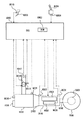
図1を参照して、本発明の実施の第1の形態に係る制御装置を搭載した車両について説明する。この車両は、FR(Front engine Rear drive)車両である。なお、FR以外の車両であってもよい。
<First Embodiment>
With reference to FIG. 1, a vehicle equipped with a control device according to a first embodiment of the present invention will be described. This vehicle is an FR (Front engine Rear drive) vehicle. A vehicle other than FR may be used.
車両は、エンジン1000と、オートマチックトランスミッション2000と、トルクコンバータ2100と、オートマチックトランスミッション2000の一部を構成するプラネタリギヤユニット3000と、オートマチックトランスミッション2000の一部を構成する油圧回路4000と、プロペラシャフト5000と、デファレンシャルギヤ6000と、後輪7000と、ECU(Electronic Control Unit)8000とを含む。
The vehicle includes an
エンジン1000は、インジェクタ(図示せず)から噴射された燃料と空気との混合気を、シリンダの燃焼室内で燃焼させる内燃機関である。燃焼によりシリンダ内のピストンが押し下げられて、クランクシャフトが回転させられる。エンジン1000により、オルタネータおよびエアコンディショナーなどの補機1004が駆動される。エンジン1000の出力トルク(エンジントルクTE)は、電子スロットルバルブ8016の作動量、すなわちスロットル開度などに応じて変化する。なお、エンジン1000の代わりにもしくは加えて、駆動源にモータを用いるようにしてもよい。また、ディーゼルエンジンを用いるようにしてもよい。ディーゼルエンジンにおいては、インジェクタの開弁時間(作動量)、すなわち燃料噴射量に応じて出力トルクが変化する。
オートマチックトランスミッション2000は、トルクコンバータ2100を介してエンジン1000に連結される。オートマチックトランスミッション2000は、所望のギヤ段を形成することにより、クランクシャフトの回転数を所望の回転数に変速する。なお、ギヤ段を形成するオートマチックトランスミッションの代わりに、ギヤ比を無段階に変更するCVT(Continuously Variable Transmission)を搭載するようにしてもよい。さらに、油圧アクチュエータもしくは電動モータにより変速される常時噛合式歯車からなる自動変速機を搭載するようにしてもよい。
オートマチックトランスミッション2000から出力された駆動力は、プロペラシャフト5000およびデファレンシャルギヤ6000を介して、左右の後輪7000に伝達される。
The driving force output from
ECU8000には、シフトレバー8004のポジションスイッチ8006と、アクセルペダル8008のアクセル開度センサ8010と、エアフローメータ8012と、電子スロットルバルブ8016のスロットル開度センサ8018と、エンジン回転数センサ8020と、入力軸回転数センサ8022と、出力軸回転数センサ8024と、油温センサ8026と、水温センサ8028とがハーネスなどを介して接続されている。
The
シフトレバー8004の位置(ポジション)は、ポジションスイッチ8006により検出され、検出結果を表す信号がECU8000に送信される。シフトレバー8004の位置に対応して、オートマチックトランスミッション2000のギヤ段が自動で形成される。また、運転者の操作に応じて、運転者が任意のギヤ段を選択できるマニュアルシフトモードを選択できるように構成してもよい。
The position (position) of
アクセル開度センサ8010は、アクセルペダル8008の開度を検出し、検出結果を表す信号をECU8000に送信する。エアフローメータ8012は、エンジン1000に吸入される空気量を検出し、検出結果を表す信号をECU8000に送信する。
スロットル開度センサ8018は、アクチュエータにより開度が調整される電子スロットルバルブ8016の開度を検出し、検出結果を表す信号をECU8000に送信する。電子スロットルバルブ8016により、エンジン1000に吸入される空気量が調整される。
The throttle opening sensor 8018 detects the opening of the
なお、電子スロットルバルブ8016の代わりにもしくは加えて、吸気バルブ(図示せず)や排気バルブ(図示せず)のリフト量や開閉する位相を変更する可変バルブリフトシステムにより、エンジン1000に吸入される空気量を調整するようにしてもよい。
In place of or in addition to the
エンジン回転数センサ8020は、エンジン1000の出力軸(クランクシャフト)の回転数(以下、エンジン回転数NEとも記載する)を検出し、検出結果を表す信号をECU8000に送信する。入力軸回転数センサ8022は、オートマチックトランスミッション2000の入力軸回転数NI(トルクコンバータ2100のタービン回転数NT)を検出し、検出結果を表す信号をECU8000に送信する。出力軸回転数センサ8024は、オートマチックトランスミッション2000の出力軸回転数NOを検出し、検出結果を表す信号をECU8000に送信する。
油温センサ8026は、オートマチックトランスミッション2000の作動や潤滑に用いられるオイル(ATF:Automatic Transmission Fluid)の温度(油温)を検出し、検出結果を表す信号をECU8000に送信する。
水温センサ8028は、エンジン1000の冷却水の温度(水温)を検出し、検出結果を表わす信号をECU8000に送信する。
Water temperature sensor 8028 detects the temperature (water temperature) of cooling water for
ECU8000は、ポジションスイッチ8006、アクセル開度センサ8010、エアフローメータ8012、スロットル開度センサ8018、エンジン回転数センサ8020、入力軸回転数センサ8022、出力軸回転数センサ8024、油温センサ8026、水温センサ8028などから送られてきた信号、ROM(Read Only Memory)8002に記憶されたマップおよびプログラムに基づいて、車両が所望の走行状態となるように、機器類を制御する。なおECU8000により実行されるプログラムをCD(Compact Disc)、DVD(Digital Versatile Disc)などの記録媒体に記録して市場に流通させてもよい。
本実施の形態において、ECU8000は、シフトレバー8004がD(ドライブ)ポジションであることにより、オートマチックトランスミッション2000のシフトレンジにD(ドライブ)レンジが選択された場合、前進1速〜8速ギヤ段のうちのいずれかのギヤ段が形成されるように、オートマチックトランスミッション2000を制御する。前進1速〜8速ギヤ段のうちのいずれかのギヤ段が形成されることにより、オートマチックトランスミッション2000は後輪7000に駆動力を伝達し得る。なおDレンジにおいて、8速ギヤ段よりも高速のギヤ段を形成可能であるようにしてもよい。形成するギヤ段は、車速とアクセル開度とをパラメータとして実験等により予め作成された変速線図に基づいて決定される。なお、ECUは複数のECUに分割するようにしてもよい。
In the present embodiment,
図2を参照して、プラネタリギヤユニット3000について説明する。プラネタリギヤユニット3000は、クランクシャフトに連結された入力軸2102を有するトルクコンバータ2100に接続されている。
The
プラネタリギヤユニット3000は、フロントプラネタリ3100と、リアプラネタリ3200と、C1クラッチ3301と、C2クラッチ3302と、C3クラッチ3303と、C4クラッチ3304と、B1ブレーキ3311と、B2ブレーキ3312と、ワンウェイクラッチ(F)3320とを含む。
The
フロントプラネタリ3100は、ダブルピニオン型の遊星歯車機構である。フロントプラネタリ3100は、第1サンギヤ(S1)3102と、1対の第1ピニオンギヤ(P1)3104と、キャリア(CA)3106と、リングギヤ(R)3108とを含む。 The front planetary 3100 is a double pinion type planetary gear mechanism. Front planetary 3100 includes a first sun gear (S1) 3102, a pair of first pinion gears (P1) 3104, a carrier (CA) 3106, and a ring gear (R) 3108.
第1ピニオンギヤ(P1)3104は、第1サンギヤ(S1)3102および第1リングギヤ(R)3108と噛合っている。第1キャリア(CA)3106は、第1ピニオンギヤ(P1)3104が公転および自転可能であるように支持している。 The first pinion gear (P1) 3104 meshes with the first sun gear (S1) 3102 and the first ring gear (R) 3108. The first carrier (CA) 3106 supports the first pinion gear (P1) 3104 so that it can revolve and rotate.
第1サンギヤ(S1)3102は、回転不能であるようにギヤケース3400に固定される。第1キャリア(CA)3106は、プラネタリギヤユニット3000の入力軸3002に連結される。
First sun gear (S1) 3102 is fixed to
リアプラネタリ3200は、ラビニヨ型の遊星歯車機構である。リアプラネタリ3200は、第2サンギヤ(S2)3202と、第2ピニオンギヤ(P2)3204と、リアキャリア(RCA)3206と、リアリングギヤ(RR)3208と、第3サンギヤ(S3)3210と、第3ピニオンギヤ(P3)3212とを含む。 The rear planetary 3200 is a Ravigneaux type planetary gear mechanism. The rear planetary 3200 includes a second sun gear (S2) 3202, a second pinion gear (P2) 3204, a rear carrier (RCA) 3206, a rear ring gear (RR) 3208, a third sun gear (S3) 3210, a third Pinion gear (P3) 3212.
第2ピニオンギヤ(P2)3204は、第2サンギヤ(S2)3202、リアリングギヤ(RR)3208および第3ピニオンギヤ(P3)3212と噛合っている。第3ピニオンギヤ(P3)3212は、第2ピニオンギヤ(P2)3204に加えて、第3サンギヤ(S3)3210と噛合っている。 Second pinion gear (P2) 3204 meshes with second sun gear (S2) 3202, rear ring gear (RR) 3208, and third pinion gear (P3) 3212. Third pinion gear (P3) 3212 meshes with third sun gear (S3) 3210 in addition to second pinion gear (P2) 3204.
リアキャリア(RCA)3206は、第2ピニオンギヤ(P2)3204および第3ピニオンギヤ(P3)3212が公転および自転可能であるように支持している。リアキャリア(RCA)3206は、ワンウェイクラッチ(F)3320に連結される。リアキャリア(RCA)3206は、1速ギヤ段の駆動時(エンジン1000から出力された駆動力を用いた走行時)に回転不能となる。リアリングギヤ(RR)3208は、プラネタリギヤユニット3000の出力軸3004に連結される。
The rear carrier (RCA) 3206 supports the second pinion gear (P2) 3204 and the third pinion gear (P3) 3212 so that they can revolve and rotate. Rear carrier (RCA) 3206 is coupled to one-way clutch (F) 3320. The rear carrier (RCA) 3206 becomes non-rotatable when driving the first gear (when traveling using the driving force output from the engine 1000). Rear ring gear (RR) 3208 is coupled to
ワンウェイクラッチ(F)3320は、B2ブレーキ3312と並列に設けられる。すなわち、ワンウェイクラッチ(F)3320のアウターレースはギヤケース3400に固定され、インナーレースはリアキャリア(RCA)3206に連結される。
The one-way clutch (F) 3320 is provided in parallel with the
図3に、各変速ギヤ段と、各クラッチおよび各ブレーキの作動状態との関係を表した作動表を示す。この作動表に示された組み合わせで各ブレーキおよび各クラッチを作動させることにより、前進1速〜8速のギヤ段と、後進1速および2速のギヤ段が形成される。 FIG. 3 shows an operation table showing the relationship between each gear position and the operation state of each clutch and each brake. By operating the brakes and the clutches in the combinations shown in the operation table, a forward 1st to 8th gear and a reverse 1st and 2nd gear are formed.
図4を参照して、油圧回路4000の要部について説明する。なお、油圧回路4000は、以下に説明するものに限られない。
The main part of the
油圧回路4000は、オイルポンプ4004と、プライマリレギュレータバルブ4006と、マニュアルバルブ4100と、ソレノイドモジュレータバルブ4200と、SL1リニアソレノイド(以下、SL(1)と記載する)4210と、SL2リニアソレノイド(以下、SL(2)と記載する)4220と、SL3リニアソレノイド(以下、SL(3)と記載する)4230と、SL4リニアソレノイド(以下、SL(4)と記載する)4240と、SL5リニアソレノイド(以下、SL(5)と記載する)4250と、SLTリニアソレノイド(以下、SLTと記載する)4300と、B2コントロールバルブ4500とを含む。
The
オイルポンプ4004は、エンジン1000のクランクシャフトに連結されている。クランクシャフトが回転することにより、オイルポンプ4004が駆動し、油圧を発生する。オイルポンプ4004で発生した油圧は、プライマリレギュレータバルブ4006により調圧され、ライン圧が生成される。
プライマリレギュレータバルブ4006は、SLT4300により調圧されたスロットル圧をパイロット圧として作動する。ライン圧は、ライン圧油路4010を介してマニュアルバルブ4100に供給される。
マニュアルバルブ4100は、ドレンポート4105を含む。ドレンポート4105から、Dレンジ圧油路4102およびRレンジ圧油路4104の油圧が排出される。マニュアルバルブ4100のスプールがDポジションにある場合、ライン圧油路4010とDレンジ圧油路4102とが連通させられ、Dレンジ圧油路4102に油圧が供給される。このとき、Rレンジ圧油路4104とドレンポート4105とが連通させられ、Rレンジ圧油路4104のRレンジ圧がドレンポート4105から排出される。
マニュアルバルブ4100のスプールがRポジションにある場合、ライン圧油路4010とRレンジ圧油路4104とが連通させられ、Rレンジ圧油路4104に油圧が供給される。このとき、Dレンジ圧油路4102とドレンポート4105とが連通させられ、Dレンジ圧油路4102のDレンジ圧がドレンポート4105から排出される。
When the spool of the
マニュアルバルブ4100のスプールがNポジションにある場合、Dレンジ圧油路4102およびRレンジ圧油路4104の両方と、ドレンポート4105とが連通させられ、Dレンジ圧油路4102のDレンジ圧およびRレンジ圧油路4104のRレンジ圧がドレンポート4105から排出される。
When the spool of the
Dレンジ圧油路4102に供給された油圧は、最終的には、C1クラッチ3301、C2クラッチ3302およびC3クラッチ3303に供給される。Rレンジ圧油路4104に供給された油圧は、最終的には、B2ブレーキ3312に供給される。
The hydraulic pressure supplied to the D range
ソレノイドモジュレータバルブ4200は、ライン圧を元圧とし、SLT4300に供給する油圧(ソレノイドモジュレータ圧)を一定の圧力に調圧する。
The
SL(1)4210は、C1クラッチ3301に供給される油圧を調圧する。SL(2)4220は、C2クラッチ3302に供給される油圧を調圧する。SL(3)4230は、C3クラッチ3303に供給される油圧を調圧する。SL(4)4240は、C4クラッチ3304に供給される油圧を調圧する。SL(5)4250は、B1ブレーキ3311に供給される油圧を調圧する。
SL (1) 4210 regulates the hydraulic pressure supplied to the
SLT4300は、アクセル開度センサ8010により検出されたアクセル開度に基づいたECU8000からの制御信号に応じて、ソレノイドモジュレータ圧を調圧し、スロットル圧を生成する。スロットル圧は、SLT油路4302を介して、プライマリレギュレータバルブ4006に供給される。スロットル圧は、プライマリレギュレータバルブ4006のパイロット圧として利用される。
The
SL(1)4210、SL(2)4220、SL(3)4230、SL(4)4240、SL(5)4250およびSLT4300は、ECU8000から送信される制御信号により制御される。
SL (1) 4210, SL (2) 4220, SL (3) 4230, SL (4) 4240, SL (5) 4250, and
B2コントロールバルブ4500は、Dレンジ圧油路4102およびRレンジ圧油路4104のいずれか一方からの油圧を選択的に、B2ブレーキ3312に供給する。B2コントロールバルブ4500に、Dレンジ圧油路4102およびRレンジ圧油路4104が接続されている。B2コントロールバルブ4500は、SLUソレノイドバルブ(図示せず)から供給された油圧とスプリングの付勢力とにより制御される。
The
SLUソレノイドバルブがオンの場合、B2コントロールバルブ4500は、図4において左側の状態となる。この場合、B2ブレーキ3312には、SLUソレノイドバルブから供給された油圧をパイロット圧として、Dレンジ圧を調圧した油圧が供給される。
When the SLU solenoid valve is on, the
SLUソレノイドバルブがオフの場合、B2コントロールバルブ4500は、図4において右側の状態となる。この場合、B2ブレーキ3312には、Rレンジ圧が供給される。
When the SLU solenoid valve is off, the
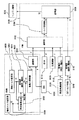
図5を参照して、本実施の形態に係る制御装置のシステム構成について説明する。図5中の「F」は駆動力を、「TE」はエンジントルクを示す。なお、以下に説明する各構成の機能は、ハードウエアにより実現するようにしてもよく、ソフトウエアにより実現するようにしてもよい。 With reference to FIG. 5, the system configuration of the control device according to the present embodiment will be described. “F” in FIG. 5 indicates the driving force, and “TE” indicates the engine torque. Note that the function of each component described below may be realized by hardware or may be realized by software.
図5に示すように、制御装置は、パワートレーンドライバモデル(PDRM: Power train Driver Model)9000と、ドライバーズサポートシステム(DSS: Drivers Support System)9024と、パワートレーンマネージャ(PTM: Power Train Manager)9100と、VDIM(Vehicle Dynamics Integrated Management)システム9110と、制振制御システム9120と、最高車速制限システム9130と、ECT(Electronic controlled Transmission)トルク制御システム9140と、エンジン制御システム9200とを備える。
As shown in FIG. 5, the control device includes a power train driver model (PDRM) 9000, a drivers support system (DSS) 9024, and a power train manager (PTM). 9100, a VDIM (Vehicle Dynamics Integrated Management)
パワートレーンドライバモデル9000は、ドライバの操作に基づいて、車両に対するドライバの要求駆動力を設定するために用いられるモデル(関数)である。本実施の形態においては、実験およびシミュレーションの結果などに基づいて予め定められたエンジントルクマップに従って、アクセル開度から要求駆動力(駆動力の要求値)が設定される。
The power
より具体的には、静的トルク設定部9002において、エンジン1000に対する静的な要求エンジントルク(エンジン1000の出力トルクの要求値)がアクセル開度から設定される。静的な要求エンジントルクとは、エンジン1000の出力トルクが安定した状態における要求エンジントルクであって、過渡的な状態を経て所定の時間の経過後に実現される要求エンジントルクを意味する。静的な要求エンジントルクは、図6に示すように、電子スロットルバルブ8016などの機器の応答性、制御時の遅れなど、時間的な影響を考慮せずに定められる。
More specifically, static
静的トルク設定部9002において設定された静的な要求エンジントルクは、変換部9004において、動的な要求エンジントルクに変換される。動的な要求エンジントルクとは、エンジン1000の出力トルクが変化し得る過渡状態における要求エンジントルクであって、速やかに実現される要求エンジントルクを意味する。動的な要求エンジントルクは、電子スロットルバルブ8016などの機器の応答性、制御時の遅れなどの時間的な影響を考慮して定められる。
The static demand engine torque set in the static
たとえば、図7に示すように、1次遅れの関数で表現されたエンジンモデルC(s)を用いてスロットルバルブ8016などの機器の制御時(作動時)における遅れを静的な要求エンジントルクに加えることにより、静的な要求エンジントルクを動的な要求エンジントルクに変換する。
For example, as shown in FIG. 7, the engine model C (s) expressed by a first-order lag function is used to set the delay during control (operation) of a device such as the
図7に示すエンジンモデルC(s)の時定数Tは、図5に示す時定数算出部9006により算出される。時定数算出部9006は、静的トルク設定部9002において設定された静的な要求エンジントルクと動的トルク設定部9008において設定された動的な要求エンジントルクとの和に応じて、時定数Tを算出する。たとえば、静的な要求エンジントルクと動的な要求エンジントルクとの和をパラメータに有するマップに従って、時定数Tが算出される。なお、時定数Tを算出する方法はこれに限らない。
The time constant T of the engine model C (s) shown in FIG. 7 is calculated by the time
静的トルク設定部9002において設定された静的な要求エンジントルクと動的トルク設定部9008において設定された動的な要求エンジントルクとの和に応じて時定数Tを算出することにより、静的トルク設定部9002において設定された静的な要求エンジントルクと動的トルク設定部9008において設定された動的な要求エンジントルクとから得られる要求エンジントルク毎に、静的な要求エンジントルクを動的な要求エンジントルクに精度よく変換することができる。
By calculating the time constant T according to the sum of the static required engine torque set in the static
本実施の形態において、動的トルク設定部9008は、エンジン1000が出力すべき最小限のエンジントルクに相当する動的な要求エンジントルクを設定する。たとえば、動的トルク設定部9008は、ISC(Idle Speed Control)により動的な要求エンジントルクを設定する。すなわち、エンジンのアイドル時において、エンジン回転数NEが予め定められた目標アイドル回転数より高くなると、予め定められた補正量だけ要求エンジントルクが小さくなるように設定される。逆に、エンジンのアイドル時において、エンジン回転数NEが予め定められた目標アイドル回転数より小さくなると、予め定められた補正量だけ要求エンジントルクが大きくなるように設定される。
In the present embodiment, dynamic
なお、動的な要求エンジンを設定する方法はこれに限らず、その他、周知のISCと同様にしてエンジン1000のアイドル時のスロットル開度を設定し、ISCにより設定されたスロットル開度から動的な要求エンジントルクを算出するようにしてもよい。
The method for setting the dynamic demand engine is not limited to this, and other than that, the throttle opening at the time of idling of the
変換部9004において静的な要求エンジントルクから変換された動的な要求エンジントルクには、動的トルク設定部9008において設定された動的な要求エンジントルクが加算される。
The dynamic demand engine torque set in the dynamic
すなわち、本実施の形態においては、アクセル開度に基づいて算出された静的な要求エンジントルクから変換された動的な要求エンジントルクと、ISCにより設定された動的な要求エンジントルクとの和が算出される。 That is, in the present embodiment, the sum of the dynamic demand engine torque converted from the static demand engine torque calculated based on the accelerator opening and the dynamic demand engine torque set by the ISC. Is calculated.
言い換えると、動的な要求エンジントルクに変換される、アクセル開度に基づいて算出された静的な要求エンジントルクと、ISCにより設定された動的な要求エンジントルクとの和が算出される。 In other words, the sum of the static demand engine torque calculated based on the accelerator opening, which is converted into the dynamic demand engine torque, and the dynamic demand engine torque set by the ISC is calculated.
最終的に得られた動的な要求エンジントルクは、駆動力変換部9020において、動的な要求駆動力に変換される。動的な要求駆動力とは、車両の駆動力が変化し得る過渡状態における要求駆動力であって、速やかに実現される要求駆動力を意味する。逆に、静的な要求駆動力とは、車両の駆動力が安定した状態における要求駆動力であって、過渡的な状態を経て所定の時間の経過後に実現される要求駆動力を意味する。
The finally obtained dynamic required engine torque is converted into a dynamic required driving force by the driving
たとえば、要求エンジントルクにオートマチックトランスミッション2000の現在のギヤ比およびデファレンシャルギヤ6000のギヤ比を乗じ、後輪7000の半径で除算することにより、要求エンジントルクが要求駆動力に変換される。なお、トルクを駆動力に変換する方法は、周知の一般的な技術を利用すればよいため、ここではその詳細な説明は繰り返さない。
For example, the required engine torque is converted into the required driving force by multiplying the required engine torque by the current gear ratio of
駆動力変換部9020において動的な要求エンジントルクから変換された動的な要求駆動力は、調停部9022において、ドライバーズサポートシステム9024により設定される動的な要求駆動力と調停される。本実施の形態においては、駆動力変換部9020において変換された動的な要求駆動力およびドライバーズサポートシステム9024により設定される動的な要求駆動力のうち、大きい方の要求駆動力が選択され、パワートレーンマネージャ9100に対して出力される。
The dynamic required driving force converted from the dynamic required engine torque in the driving
ドライバーズサポートシステム9024は、クルーズコントロールシステム、パーキングアシストシステムおよびプリクラッシュセーフティシステムなどにより、車両の挙動に応じて動的な要求駆動力を自動的に設定する。
The driver's
パワートレーンマネージャ9100は、パワートレーンドライバモデル9000、VDIMシステム9110、制振制御システム9120、最高車速制限システム9130から入力される動的な要求駆動力およびECTトルク制御システム9140から入力される動的な要求エンジントルクに基づいて、最終的にエンジン1000の制御に用いられる動的な要求エンジントルクを設定する。
The
より具体的には、調停部9102において、パワートレーンドライバモデル9000、VDIMシステム9110、制振制御システム9120、最高車速制限システム9130から入力される動的な要求駆動力が調停される。本実施の形態においては、最も小さい要求駆動力が選択され、トルク変換部9104に対して出力される。
More specifically, the
調停部9102において調停された動的な要求駆動力は、トルク変換部9104において動的な要求エンジントルクに変換される。
The dynamic required driving force adjusted by the
トルク変換部9104において要求駆動力から変換された動的な要求エンジントルクおよびECTトルク制御システム9140から入力される動的な要求エンジントルクは、調停部9106において調停される。2つの要求エンジントルクのうちの小さい方の要求エンジントルクもしくは大きい方の要求エンジントルクが選択され、エンジン制御システム9200に対して出力される。小さい方の要求エンジントルクおよび大きい方の要求エンジントルクのうちのどちらの要求エンジントルクを選択するかは、車両の運転状態などに応じて決定される。
The dynamic request engine torque converted from the required driving force in the
エンジン制御システム9200は、パワートレーンマネージャ9100から入力された動的な要求エンジントルクを実現するように、電子スロットルバルブ8016、点火時期、EGR(Exhaust Gas Recirculation)バルブなど、エンジン1000の出力トルクを制御するためにエンジン1000に設けられた機器を制御する。
The
したがって、パワートレーンドライバモデル9000から出力された動的な要求駆動力に応じてエンジン1000が制御されるのであれば、動的な要求エンジントルクに変換される、アクセル開度に基づいて算出された静的な要求エンジントルクと、ISCにより設定された動的な要求エンジントルクとの和に応じて、エンジン1000が制御される。
Therefore, if the
VDIMシステム9110は、VSC(Vehicle Stability Control)、TRC(TRaction Control)、ABS(Anti lock Brake System)、EPS(Electric Power Steering)などを統合するシステムであって、アクセル、ステアリング、ブレーキの操作量によるドライバの走行イメージと、各種センサ情報による車両挙動との差を算出し、その差を縮めるように車両の駆動力、ブレーキ油圧などを制御する。
The
VSCは、前後輪が横滑りしそうな状態をセンサが検出して場合において、各輪のブレーキ油圧および車両の動的な要求駆動力などの最適値を自動的に設定し、車両の安定性を確保する制御である。 VSC automatically sets optimal values such as the brake hydraulic pressure of each wheel and the dynamic required driving force of the vehicle when the sensor detects that the front and rear wheels are likely to slip sideways to ensure vehicle stability. It is control to do.
TRCは、滑りやすい路面での発進時および加速時に、駆動輪の空転をセンサが感知すると、各輪のブレーキ油圧および車両の動的な要求駆動力などの最適値を自動的に設定し、最適な駆動力を確保する制御である。 TRC automatically sets optimal values such as the brake hydraulic pressure of each wheel and the dynamic required driving force of the vehicle when the sensor detects idling of the driving wheel when starting and accelerating on a slippery road surface. This is a control that ensures a sufficient driving force.
ABSは、ブレーキ油圧の最適値を自動的に設定し、車輪のロックを防止する制御システムである。EPSは、電動モータの力によってステアリングホイールの操舵をアシストする制御システムである。 ABS is a control system that automatically sets an optimum value of brake hydraulic pressure and prevents wheel lock. EPS is a control system that assists steering of a steering wheel by the force of an electric motor.
VDIMシステム9110において設定された動的な要求駆動力は、パワートレーンマネージャ9100の調停部9102に入力される。
The dynamic requested driving force set in the
制振制御システム9120は、車両の実際の駆動力などから、車両モデルを用いて算出される車両のピッチングおよびバウンシングを抑制するための動的な要求駆動力を設定す
る。車両のピッチングおよびバウンシングを抑制するための駆動力を設定する方法については、従来の技術を利用すればよいため、ここではその詳細な説明は繰り返さない。
The vibration
最高車速制限システム9130は、車速を予め定められた最高車速以下に制限するための静的な要求駆動力を、たとえば現在の加速度および車速などに応じて設定する。最高車速制限システム9130により設定された静的な要求駆動力は、変換部9132において動的な要求駆動力に変換される。
Maximum vehicle
ECTトルク制御システム9140は、オートマチックトランスミッション2000の変速時にエンジン1000に対して要求する静的な要求エンジントルクを設定する。ECTトルク制御システム9140が設定する静的な要求エンジントルクは、たとえば、変速ショックを低減するためのトルクダウンもしくはトルクアップを実現し得るように設定される。
The ECT
ECTトルク制御システム9140により設定された静的な要求エンジントルクは、変換部9142により動的な要求エンジントルクに変換される。
The static demand engine torque set by the ECT
以上のように、本実施の形態に係る制御装置によれば、アクセル開度に基づいた静的な要求エンジントルクおよびISCによる動的な要求エンジントルクが設定される。静的な要求エンジントルクは、静的な要求エンジントルクおよび動的な要求エンジントルクに応じて、動的な要求エンジントルクに変換される。これにより、静的な要求エンジントルクによる影響ならびに動的な要求エンジントルクによる影響の両方を考慮して、静的な要求エンジントルクを動的な要求エンジントルクに精度よく変換することができる。アクセル開度に基づいた静的な要求エンジントルクから変換された動的な要求エンジントルクには、ISCにより設定された動的な要求エンジントルクが加算される。最終的に得られた要求エンジントルクに応じてエンジンが制御される。これにより、アクセル開度に基づいて算出された静的な要求エンジントルクから変換された動的な要求エンジントルクと、ISCにより設定された動的な要求エンジントルクとの和に応じてエンジンを制御することができる。言い換えると、動的な要求エンジントルクに変換される、アクセル開度に基づいて算出された静的な要求エンジントルクと、ISCにより設定された動的な要求エンジントルクとの和に応じて、エンジンを制御することができる。 As described above, according to the control device according to the present embodiment, the static required engine torque based on the accelerator opening and the dynamic required engine torque based on ISC are set. The static demand engine torque is converted into a dynamic demand engine torque in response to the static demand engine torque and the dynamic demand engine torque. Accordingly, it is possible to accurately convert the static demand engine torque into the dynamic demand engine torque in consideration of both the influence of the static demand engine torque and the influence of the dynamic demand engine torque. The dynamic demand engine torque set by the ISC is added to the dynamic demand engine torque converted from the static demand engine torque based on the accelerator opening. The engine is controlled according to the finally obtained required engine torque. This controls the engine according to the sum of the dynamic demand engine torque converted from the static demand engine torque calculated based on the accelerator opening and the dynamic demand engine torque set by the ISC. can do. In other words, depending on the sum of the static demand engine torque calculated based on the accelerator opening and converted to the dynamic demand engine torque, and the dynamic demand engine torque set by the ISC, the engine Can be controlled.
なお、エンジントルクの代わりにタービントルク(トルクコンバータ2100の出力トルク)の要求値を算出するようにしてもよい。 Instead of the engine torque, a required value of turbine torque (output torque of torque converter 2100) may be calculated.
<第2の実施の形態>
以下、本発明の第2の実施の形態について説明する。本実施の形態は、静的な要求エンジントルクおよび動的な要求エンジントルクの2つのパラメータを有するマップを用いて、静的な要求エンジントルクを動的な要求エンジントルクに変換する点で、前述の第1の実施の形態と相違する。
<Second Embodiment>
Hereinafter, a second embodiment of the present invention will be described. In the present embodiment, the static demand engine torque is converted into the dynamic demand engine torque using a map having two parameters of the static demand engine torque and the dynamic demand engine torque. This is different from the first embodiment.
図8を参照して、本実施の形態における時定数算出部9030は、静的な要求エンジントルクおよび動的な要求エンジントルクの2つのパラメータを有するマップに従って、エンジンモデルC(s)の時定数Tを算出する。
Referring to FIG. 8, time
これにより、静的な要求エンジントルクと動的な要求エンジントルクとをパラメータとして有するマップを用いて、静的トルク設定部9002において設定された静的な要求エンジントルクを動的な要求エンジントルクに変換することができる。
As a result, using the map having the static demand engine torque and the dynamic demand engine torque as parameters, the static demand engine torque set in the static
時定数Tを算出するために用いられるマップは、図9に示すように、静的な要求エンジントルクと動的な要求エンジントルクと用いて収束演算を行なって、静的な要求エンジントルクから動的な要求エンジントルクへの変換に用いられるパラメータ(時定数T)を予め算出しておくことにより、予め用意される。 As shown in FIG. 9, the map used to calculate the time constant T is calculated from the static demand engine torque by performing a convergence operation using the static demand engine torque and the dynamic demand engine torque. It is prepared in advance by calculating in advance a parameter (time constant T) that is used for conversion to the required engine torque.
このようにすれば、静的トルク設定部9002において設定された静的な要求エンジントルクと動的トルク設定部9008において設定された動的な要求エンジントルクとの組み合せ毎に、静的な要求エンジントルクを動的な要求エンジントルクに精度よく変換することができる。
In this way, for each combination of the static demand engine torque set in the static
今回開示された実施の形態は、すべての点で例示であって制限的なものではないと考えられるべきである。本発明の範囲は上記した説明ではなくて特許請求の範囲によって示され、特許請求の範囲と均等の意味および範囲内でのすべての変更が含まれることが意図される。 The embodiment disclosed this time should be considered as illustrative in all points and not restrictive. The scope of the present invention is defined by the terms of the claims, rather than the description above, and is intended to include any modifications within the scope and meaning equivalent to the terms of the claims.
1000 エンジン、1004 補機、2000 オートマチックトランスミッション、2100 トルクコンバータ、5000 プロペラシャフト、6000 デファレンシャルギヤ、7000 後輪、8000 ECU、8002 ROM、8004 シフトレバー、8006 ポジションスイッチ、8008 アクセルペダル、8010 アクセル開度センサ、8012 エアフローメータ、8016 電子スロットルバルブ、8018
スロットル開度センサ、8020 エンジン回転数センサ、8022 入力軸回転数センサ、8024 出力軸回転数センサ、8026 油温センサ、8028 水温センサ、9000 パワートレーンドライバモデル、9002 静的トルク設定部、9004 変換部、9006,9030 時定数算出部、9008 動的トルク設定部、9020 駆動力変換部、9022 調停部、9024 ドライバーズサポートシステム、9100 パワートレーンマネージャ、9102 調停部、9104 トルク変換部、9106 調停部、9110 VDIMシステム、9120 制振制御システム、9130 最高車速制限システム、9132 変換部、9140 トルク制御システム、9142 変換部、9200 エンジン制御システム。
1000 engine, 1004 auxiliary machine, 2000 automatic transmission, 2100 torque converter, 5000 propeller shaft, 6000 differential gear, 7000 rear wheel, 8000 ECU, 8002 ROM, 8004 shift lever, 8006 position switch, 8008 accelerator pedal, 8010 accelerator opening sensor , 8012 Air flow meter, 8016 Electronic throttle valve, 8018
Throttle opening sensor, 8020 engine speed sensor, 8022 input shaft speed sensor, 8024 output shaft speed sensor, 8026 oil temperature sensor, 8028 water temperature sensor, 9000 powertrain driver model, 9002 static torque setting unit, 9004
Claims (4)
前記エンジンの過渡状態における前記エンジンの出力トルクの要求値である動的な第2の要求値を、車両の挙動に基づいて自動的に設定するための手段と、
前記第1の要求値および前記第2の要求値に応じて、前記エンジンの出力トルクの動的な第3の要求値に前記第1の要求値を変換するための変換手段と、
前記第2の要求値および前記第3の要求値の和に応じて前記エンジンを制御するための手段とを備える、駆動源の制御装置。 Means for setting a static first required value, which is a required value of the output torque of the engine in a steady state of the engine as a drive source , according to an accelerator opening ;
Means for automatically setting a dynamic second required value, which is a required value of the output torque of the engine in a transient state of the engine , based on the behavior of the vehicle ;
Conversion means for converting the first required value into a dynamic third required value of the output torque of the engine according to the first required value and the second required value;
A drive source control device comprising: means for controlling the engine in accordance with a sum of the second required value and the third required value.
Priority Applications (2)
| Application Number | Priority Date | Filing Date | Title |
|---|---|---|---|
| JP2008198302A JP4600540B2 (en) | 2008-07-31 | 2008-07-31 | Drive source control device |
| US12/505,870 US7983826B2 (en) | 2008-07-31 | 2009-07-20 | Control apparatus and control method for drive source |
Applications Claiming Priority (1)
| Application Number | Priority Date | Filing Date | Title |
|---|---|---|---|
| JP2008198302A JP4600540B2 (en) | 2008-07-31 | 2008-07-31 | Drive source control device |
Publications (2)
| Publication Number | Publication Date |
|---|---|
| JP2010037951A JP2010037951A (en) | 2010-02-18 |
| JP4600540B2 true JP4600540B2 (en) | 2010-12-15 |
Family
ID=41609177
Family Applications (1)
| Application Number | Title | Priority Date | Filing Date |
|---|---|---|---|
| JP2008198302A Expired - Fee Related JP4600540B2 (en) | 2008-07-31 | 2008-07-31 | Drive source control device |
Country Status (2)
| Country | Link |
|---|---|
| US (1) | US7983826B2 (en) |
| JP (1) | JP4600540B2 (en) |
Families Citing this family (3)
| Publication number | Priority date | Publication date | Assignee | Title |
|---|---|---|---|---|
| JP4702429B2 (en) | 2008-10-16 | 2011-06-15 | トヨタ自動車株式会社 | Drive source control device |
| JP4678444B2 (en) * | 2009-04-09 | 2011-04-27 | トヨタ自動車株式会社 | Vehicle control device |
| JP5273121B2 (en) * | 2010-10-19 | 2013-08-28 | 株式会社デンソー | Start support device |
Citations (7)
| Publication number | Priority date | Publication date | Assignee | Title |
|---|---|---|---|---|
| JPH1182090A (en) * | 1997-09-09 | 1999-03-26 | Toyota Motor Corp | Internal combustion engine control system |
| JP2003214231A (en) * | 2002-01-29 | 2003-07-30 | Nissan Motor Co Ltd | Torque control device for engine |
| JP2004308649A (en) * | 2003-04-07 | 2004-11-04 | Robert Bosch Gmbh | Driving method for drive unit of vehicle |
| JP2005155410A (en) * | 2003-11-25 | 2005-06-16 | Nissan Motor Co Ltd | Engine torque control device |
| JP2006138265A (en) * | 2004-11-12 | 2006-06-01 | Toyota Motor Corp | Torque control device for vehicle |
| JP2006170079A (en) * | 2004-12-16 | 2006-06-29 | Nissan Motor Co Ltd | Intake control device for internal combustion engine |
| JP2006183506A (en) * | 2004-12-27 | 2006-07-13 | Hitachi Ltd | Control device for engine |
Family Cites Families (13)
| Publication number | Priority date | Publication date | Assignee | Title |
|---|---|---|---|---|
| US5157608A (en) * | 1990-09-14 | 1992-10-20 | Ford Motor Company | Electronic control system for multiple ratio transmission including circuit pressure control |
| US5305663A (en) * | 1992-08-10 | 1994-04-26 | Ford Motor Company | Automatic transmission control system |
| DE19845157A1 (en) * | 1998-10-01 | 2000-04-06 | Zahnradfabrik Friedrichshafen | Controlling torque of motor vehicle IC engine with automatic gearbox so that continuous signals are exchanged between DME and electronic gearbox control across CAN data bus and engine torque also associated engine parameters |
| US6358184B1 (en) * | 2000-03-20 | 2002-03-19 | General Motors Corporation | Model-based control of an automatic transmission garage shift |
| DE10047502A1 (en) * | 2000-09-26 | 2002-04-11 | Bosch Gmbh Robert | Controlling drive unit revolution rate for starter motor of an IC engine, involves controlling electrical machine applying torque to engine depending on deviation between demand and actual revolution rates in starting phase |
| FR2827339B1 (en) | 2001-07-12 | 2005-11-11 | Renault | DEVICE FOR CONTROLLING THE OPERATING POINT OF THE POWER UNIT OF A VEHICLE |
| US6687582B1 (en) * | 2002-08-08 | 2004-02-03 | Visteon Global Technologies, Inc. | Control of idle speed in a hybrid powertrain configuration |
| US6790159B1 (en) * | 2003-02-21 | 2004-09-14 | Borgwarner, Inc. | Method of controlling a dual clutch transmission |
| US6819997B2 (en) * | 2003-02-21 | 2004-11-16 | Borgwarner, Inc. | Method of controlling a dual clutch transmission |
| FR2870792B1 (en) | 2004-05-28 | 2007-08-31 | Renault Sas | METHOD FOR MONITORING A TORQUE SETTING TO BE APPLIED TO WHEELS OF AN AUTOMATED TRANSMISSION FOR MOTOR VEHICLE AND CORRESPONDING DEVICE |
| JP4525434B2 (en) * | 2005-04-13 | 2010-08-18 | トヨタ自動車株式会社 | Vehicle driving force control device |
| JP4432861B2 (en) * | 2005-08-22 | 2010-03-17 | トヨタ自動車株式会社 | Vehicle driving force control device |
| JP4466539B2 (en) * | 2005-11-08 | 2010-05-26 | トヨタ自動車株式会社 | Control device for internal combustion engine |
-
2008
- 2008-07-31 JP JP2008198302A patent/JP4600540B2/en not_active Expired - Fee Related
-
2009
- 2009-07-20 US US12/505,870 patent/US7983826B2/en not_active Expired - Fee Related
Patent Citations (7)
| Publication number | Priority date | Publication date | Assignee | Title |
|---|---|---|---|---|
| JPH1182090A (en) * | 1997-09-09 | 1999-03-26 | Toyota Motor Corp | Internal combustion engine control system |
| JP2003214231A (en) * | 2002-01-29 | 2003-07-30 | Nissan Motor Co Ltd | Torque control device for engine |
| JP2004308649A (en) * | 2003-04-07 | 2004-11-04 | Robert Bosch Gmbh | Driving method for drive unit of vehicle |
| JP2005155410A (en) * | 2003-11-25 | 2005-06-16 | Nissan Motor Co Ltd | Engine torque control device |
| JP2006138265A (en) * | 2004-11-12 | 2006-06-01 | Toyota Motor Corp | Torque control device for vehicle |
| JP2006170079A (en) * | 2004-12-16 | 2006-06-29 | Nissan Motor Co Ltd | Intake control device for internal combustion engine |
| JP2006183506A (en) * | 2004-12-27 | 2006-07-13 | Hitachi Ltd | Control device for engine |
Also Published As
| Publication number | Publication date |
|---|---|
| US20100030398A1 (en) | 2010-02-04 |
| US7983826B2 (en) | 2011-07-19 |
| JP2010037951A (en) | 2010-02-18 |
Similar Documents
| Publication | Publication Date | Title |
|---|---|---|
| JP4678444B2 (en) | Vehicle control device | |
| JP4561889B2 (en) | Output torque calculation device | |
| JP5195932B2 (en) | Vehicle control apparatus and control method | |
| JP5257508B2 (en) | Drive source control apparatus and control method | |
| JP2009167873A (en) | Control device for power source | |
| JP4600540B2 (en) | Drive source control device | |
| JP2009173158A (en) | Control device for power train | |
| JP4702429B2 (en) | Drive source control device | |
| JP4872985B2 (en) | Drive source control device | |
| JP5082883B2 (en) | Powertrain control device | |
| JP4957566B2 (en) | Powertrain control device | |
| JP2009243284A (en) | Control device of drive source | |
| JP2009250085A (en) | Control device of driving source | |
| JP5136653B2 (en) | Powertrain control device and control method | |
| JP2009250084A (en) | Control device of driving source | |
| JP2010236416A (en) | Abnormality determination device for vehicle | |
| JP4894778B2 (en) | Engine control device | |
| JP2010121491A (en) | Control device for drive source | |
| JP2010096093A (en) | Control device for drive source | |
| JP2010120488A (en) | A drive source control device | |
| JP2010071356A (en) | Control device of indicator | |
| JP2010169019A (en) | Control device for drive source |
Legal Events
| Date | Code | Title | Description |
|---|---|---|---|
| A977 | Report on retrieval |
Free format text: JAPANESE INTERMEDIATE CODE: A971007 Effective date: 20100430 |
|
| A131 | Notification of reasons for refusal |
Free format text: JAPANESE INTERMEDIATE CODE: A131 Effective date: 20100511 |
|
| A521 | Written amendment |
Free format text: JAPANESE INTERMEDIATE CODE: A523 Effective date: 20100702 |
|
| TRDD | Decision of grant or rejection written | ||
| A01 | Written decision to grant a patent or to grant a registration (utility model) |
Free format text: JAPANESE INTERMEDIATE CODE: A01 Effective date: 20100831 |
|
| A01 | Written decision to grant a patent or to grant a registration (utility model) |
Free format text: JAPANESE INTERMEDIATE CODE: A01 |
|
| A61 | First payment of annual fees (during grant procedure) |
Free format text: JAPANESE INTERMEDIATE CODE: A61 Effective date: 20100913 |
|
| FPAY | Renewal fee payment (event date is renewal date of database) |
Free format text: PAYMENT UNTIL: 20131008 Year of fee payment: 3 |
|
| R151 | Written notification of patent or utility model registration |
Ref document number: 4600540 Country of ref document: JP Free format text: JAPANESE INTERMEDIATE CODE: R151 |
|
| FPAY | Renewal fee payment (event date is renewal date of database) |
Free format text: PAYMENT UNTIL: 20131008 Year of fee payment: 3 |
|
| LAPS | Cancellation because of no payment of annual fees |