JP4598985B2 - Filling nozzle of fluid filling machine - Google Patents
Filling nozzle of fluid filling machine Download PDFInfo
- Publication number
- JP4598985B2 JP4598985B2 JP2001128027A JP2001128027A JP4598985B2 JP 4598985 B2 JP4598985 B2 JP 4598985B2 JP 2001128027 A JP2001128027 A JP 2001128027A JP 2001128027 A JP2001128027 A JP 2001128027A JP 4598985 B2 JP4598985 B2 JP 4598985B2
- Authority
- JP
- Japan
- Prior art keywords
- filling
- mesh
- nozzle
- liquid
- filling nozzle
- Prior art date
- Legal status (The legal status is an assumption and is not a legal conclusion. Google has not performed a legal analysis and makes no representation as to the accuracy of the status listed.)
- Expired - Lifetime
Links
Images


Description
【0001】
【発明の属する技術分野】
本発明は、例えば、調味液や、洗剤、薬品などの液体の商品などの流体をボトル容器に充填する流体充填機の充填ノズルに関する。
【0002】
【従来の技術】
一般に、例えば合成樹脂、ガラス製等のボトル容器内に調味液や、洗剤、薬品などの液体の商品を所定容量充填する作業を行なう流体充填機の充填ノズルでは、図6に示すようにノズルaの先端に金網状のメッシュbを取り付け、充填ノズルaから吐出される充填液の流れをノズルaの先端のメッシュbを通過させることにより整流して発泡を抑制することは従来から行われている。
【0003】
また、従来の充填ノズルaでは図6に示すように筒状の充填ノズル本体cの吐出口dの周縁部位に内方向に向けて爪状の取付け部(メッシュ止め堰)eが突設されている。そして、充填ノズル本体cの筒体内に挿入されたノズル先端メッシュbをこの取付け部eに突き当てた状態で取付ける構成になっている。
【0004】
さらに、網目構造のノズル先端メッシュbを充填ノズル本体cに固定する他の固定構造としては図7に示すように充填ノズル本体cの先端部にノズル先端メッシュbをカシメ加工することにより、取付ける構成のものもある。この場合、充填ノズル本体cの先端部にはノズル先端メッシュbのカシメ加工部fが充填ノズル本体cの吐出口dの周縁部位に内方向に向けて突設されている。
【0005】
【発明が解決しようとする課題】
上記従来構成の流体充填機の充填ノズルでは充填ノズル本体cの吐出口dの周縁部位に爪状の取付け部eや、カシメ加工部fが内方向に向けて突設されているので、ノズル先端メッシュbを充填ノズル本体cの吐出口dの周縁部位に取付けた際に、充填ノズル本体cにおける吐出口dの取付け部eや、カシメ加工部fの部分に図6および図7に示すように取付け部eや、カシメ加工部fの厚さ分の段差S1,S2が形成される。そのため、このようなノズル先端メッシュbの取付け構造では充填ノズル本体cの吐出口dに露出されるノズル先端メッシュbの端面の位置と、充填ノズル本体cにおける吐出口dの周縁部位の端面の位置、すなわち吐出口dの取付け部eや、カシメ加工部fの外端面の位置との間には段差が形成されているので、流体充填機の充填ノズルからの充填液の充填後、充填液の供給が停止された際に、ノズル先端メッシュbの端面と、充填ノズル本体cにおける吐出口dの周縁部位の端面との間の段差部のノズル内壁面に充填液が付着したまま残留するおそれがある。このような場合には充填液の充填後に充填ノズルの先端部のノズル内壁面に付着した充填液が滴下する液垂れ現象が発生し易く、容器や機械に液を付着させて不良品の発生やトラブルの原因となる問題がある。
【0006】
また、上記従来構成の流体充填機の充填ノズルでは充填ノズル本体cの吐出口dに装着されるノズル先端メッシュbが1段であるため、充填ノズルの吐出口dから吐出されるノズル吐出液の偏流(偏った流れ)が発生するおそれがある。この場合には、充填ノズルの吐出口dから吐出される充填液の流れの断面が真円になりにくいので、充填ノズルの吐出口dから吐出される充填液の流れが不均一な流れとなるため、層流になりにくく、充填液の充填時に容器内の充填液の発泡などが発生する問題がある。
【0007】
本発明は上記事情に着目してなされたもので、その目的は、充填ノズルの吐出口から吐出される充填液の流れを均一な層流にすることができ、充填液の充填時に容器内の充填液の発泡などの発生を防止することができるとともに、充填液の充填後にノズル先端部から充填液が滴下する液垂れ現象の発生を防止することができる流体用充填機の充填ノズルを提供することにある。
【0008】
【課題を解決するための手段】
本発明は、充填液を流す液体管路の吐出端部に筒状の充填ノズルの本体が配設されるとともに、前記充填ノズル本体内に充填液の流れを整流して発泡を抑制する網目構造のノズル先端メッシュが配設され、かつ前記筒状の充填ノズル本体の吐出口の周縁部位に前記ノズル先端メッシュを取付ける取付け部が内方向に向けて突設された流体充填機の充填ノズルにおいて、
前記ノズル先端メッシュを充填液の流れ方向に沿って複数段のメッシュ構成体を積層させた積層体によって形成するとともに、
前記メッシュ構成体の網目の粗さを前記積層体の各段毎に変化させ、前記充填液の流れの上流側に比べて下流側に網目の細かい前記メッシュ構成体を配設し、
かつ前記充填液の流れの最下流位置の前記メッシュ構成体に前記充填ノズル本体の吐出口周縁の取付け部の段差を埋めて前記充填ノズル本体の吐出口に前記充填ノズル本体の先端面と前記メッシュ構成体の端面とを同一面に並べた平滑面を形成する平滑面形成部を設け、
前記平滑面形成部は、前記充填ノズル本体の吐出口の前記取付け部の形状と対応する形状の突出部を前記メッシュ構成体の端面に突設させ、前記メッシュ構成体の突出部を前記充填ノズル本体の前記取付け部に嵌合させたものであることを特徴とする流体充填機の充填ノズルである。
そして、本発明では、充填ノズル本体の内部で充填液を複数段のメッシュ構成体を積層させた積層体における上流側の網目の粗いメッシュ構成体から下流側の網目の細かいメッシュ構成体に順次浸透させることにより、充填液の流れを効果的に整流して層流化し、発泡を抑制する。さらに、充填液の流れの最下流位置のメッシュ構成体の平滑面形成部を充填ノズル本体の吐出口周縁の取付け部の段差部に挿入させることにより、充填ノズル本体の吐出口周縁の取付け部の段差を埋めて充填ノズル本体の吐出口に充填ノズル本体の先端面とメッシュ構成体の端面とを同一面に並べた平滑面を形成するようにしたものである。
【0009】
さらに、メッシュ構成体の端面に突設させた突出部を充填ノズル本体の取付け部に嵌合させることにより、充填ノズル本体の吐出口周縁の取付け部の段差を埋めて充填ノズル本体の吐出口に平滑面を形成するようにしたものである。
【0010】
【発明の実施の形態】
以下、本発明の第1の実施の形態を図面を参照して説明する。図1は本実施の形態の流体充填機1の概略構成を示すものである。この流体充填機1には、例えば、調味液や、洗剤、薬品などの液体の供給路2に接続された充填バルブ3が設けられている。この充填バルブ3のバルブハウジング4内には略L字状に屈曲された充填液の流路(流体室)5が形成されている。この充填液流路5には略水平方向に延設された水平方向流路5aと、略鉛直方向に延設された鉛直方向流路(液体管路)5bとが設けられている。なお、このバルブハウジング4は、流体充填機1の機体(図示せず)に取り付けられていて、その下側に、流体を容器23内へ充填する充填ノズル7が配設されている。
【0011】
また、バルブハウジング4には水平方向流路5aの外端部に充填液の流入口6、鉛直方向流路5bの下端部に充填ノズル7がそれぞれ配設されている。さらに、流入口6には液体供給路2の一端部が連結されている。この液体供給路2の他端部は調味液や、洗剤、薬品などの供給液体を貯留する液体タンク8に接続されている。そして、液体タンク8から液体供給路2を介して流入口6よりバルブハウジング4の充填液流路5内に液体が供給されて、流入した流体がこの充填液流路5内に所定量蓄溜されるようになっている。
【0012】
また、図2に示すようにバルブハウジング4内には水平方向流路5aと、鉛直方向流路5bとの間の交差部に円形の流体流通口9aを備えたリング状の弁座部9が形成されている。さらに、弁座部9よりも下側の鉛直方向流路5b内にはこの弁座部9に接離可能に当接されるバルブ本体10が配設されている。そして、このバルブ本体10が鉛直方向に進退駆動されることにより、弁座部9に対して接離操作されるようになっている。このとき、バルブ本体10が鉛直方向に移動されるバルブストロークに応じて弁座部9の流体流通口9aの開度(開口面積)が変化し、充填ノズル7から外部に吐出される液体流量が変化するようになっている。
【0013】
また、充填バルブ3の上側にはこの充填バルブ3のバルブ本体10を駆動するバルブ駆動部11が配設されている。このバルブ駆動部11は例えば空圧回路等によって駆動される流体シリンダによって形成されている。さらに、このバルブ駆動部11の流体シリンダのピストンロッド11aの下部に位置するロッド12の下端部にバルブ本体10が固定されている。そして、バルブ駆動部11によってバルブ本体10が図5(C)に示す停止位置から複数段、本実施の形態では例えば図5(A)に示す大流量ストロークと、図5(B)に示す小流量ストロークの2段階のバルブストロークに移動され、このバルブ本体10の移動動作に応じて弁座部9の流体流通口9aの開度を調整して充填ノズル7からの液体の吐出流量を制御するようになっている。
【0014】
なお、バルブ駆動部11の流体シリンダのロッド12は、充填バルブ3とバルブ駆動部11との間に配設された中間の支持部材13に設けた圧縮コイルばね14により常に上方へ付勢されるように取り付けられている。これにより、バルブ本体10が常時閉塞(停止位置)方向に付勢されるため、液垂れを生ずることがなく安定に保たれる。
【0015】
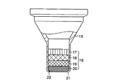
また、充填ノズル7には充填バルブ3のバルブハウジング4の下端部に連結された筒状の充填ノズル本体15が設けられている。この充填ノズル本体15内には充填液の流れを整流して発泡を抑制する網目構造のノズル先端メッシュ16が配設されている。このノズル先端メッシュ16は図3に示すように充填液の流れ方向に沿って複数段、本実施の形態では4段のメッシュ構成体17,18,19,20を積層させた積層体によって形成されている。
【0016】
さらに、4段のメッシュ構成体17,18,19,20の網目の粗さはノズル先端メッシュ16の積層体の各段毎に変化させ、充填液の流れの上流側に比べて下流側に網目の細かいメッシュ構成体を配設するように設定されている。例えば、本実施の形態では充填液の流れの最上流位置の第1のメッシュ構成体17はストレートメッシュによって形成されている。この最上流位置メッシュ構成体17のストレートメッシュは例えば水道の蛇口に入っているような薄板を折り曲げて形成されている。また、最上流位置メッシュ構成体17の下段の第2のメッシュ構成体18は20メッシュの上段クロスメッシュによって形成されている。さらに、この第2のメッシュ構成体18の下段の第3のメッシュ構成体19は30メッシュの中段クロスメッシュ、この第3のメッシュ構成体19の下段の第4のメッシュ構成体20は40メッシュの下段クロスメッシュによってそれぞれ形成されている。なお、第2〜4の各メッシュ構成体18,19,20のデータは次の表1の通りである。
【0017】
【表1】

すなわち、本実施の形態のノズル先端メッシュ16の積層体は、充填ノズル本体15内における充填液の流れの最下流位置に網目ピッチが0.64mmで、充填ノズル本体15の吐出口15aの開口面積に対するメッシュ構成体における充填液の流路面積の比である開孔面積比が51.7%の下段メッシュ構成体20、この下段メッシュ構成体20の上に網目ピッチが0.85mmで、開孔面積比が49.8%の中段メッシュ構成体19、この中段メッシュ構成体19の上に網目ピッチが1.27mmで、開孔面積比が50.2%の上段メッシュ構成体18、この上段メッシュ構成体18の上に薄板を折り曲げて形成され、充填液の流路方向に沿って充填液の流れを整流する最上段のストレートメッシュ構成体17がそれぞれ積層されている。
【0019】
また、図4(A)に示すように充填ノズル本体15の吐出口15aの周縁部位にはノズル先端メッシュ16の積層体を取付ける取付け部21が内方向に向けて突設されている。この取付け部21は充填ノズル本体15の吐出口15aの周縁部位を内方向に向けて略直角に折り返した状態に曲げ加工されたリング状の段付部によって形成されている。
【0020】
さらに、図4(B)に示すように充填液の流れの最下流位置の第4のメッシュ構成体20の下端面には他の部分よりも小径な小径部(平滑面形成部)22が突設されている。この小径部22の外径寸法D2は充填ノズル本体15の吐出口15aの周縁の取付け部21の内径寸法D1とほぼ同径に設定されている。なお、この第4のメッシュ構成体20の小径部22の高さT2は取付け部21の厚さ(段差の高さ)T1と同等に設定されている。そして、第4のメッシュ構成体20の小径部22は充填ノズル本体15の吐出口15a周縁の取付け部21の内部に嵌合させた状態で取付けられている。これにより、充填ノズル本体15の吐出口15aの周縁の取付け部21の段差を埋めて充填ノズル本体15の吐出口15aに充填ノズル本体15の先端面と第4のメッシュ構成体20の端面とを同一面に並べた平滑面が形成されている。
【0021】
また、充填ノズル7の下方には充填液が充填されるガラスやプラスチック製の容器23を搬送する容器搬送路24が配設されている。この容器搬送路24には容器23を1本ずつ載せるテーブル25が配設されている。このテーブル25にはロードセル等による計量手段26が装着されている。
【0022】
そして、本実施の形態では流体充填機1の駆動時には容器搬送路24のテーブル25に載った容器23が充填ノズル7の下方位置に搬送されるようになっている。このとき、充填ノズル7は容器23の口元の上側に離れた位置で停止され、この離れた位置の充填ノズル7からテーブル25上の容器23に充填液を充填させる口外充填方式が採用されている。そして、この状態で、充填ノズル7から吐出される充填液が容器23の内部に充填されるようになっている。
【0023】
また、充填液の充填後、充填液が充填済みの容器23は次の工程に搬送され、充填ノズル7の下には次の空の容器23がセットされ、以後、充填ノズル7から吐出される充填液が容器23の内部に充填される充填液の充填作業が同様に繰り返されるようになっている。
【0024】
次に、上記構成の作用について説明する。本実施の形態の流体充填機1の通常運転時には図1に示すように液体タンク8から液体の供給路2を介して調味液や、洗剤、薬品などの液体の商品を流体充填機1に給液する動作が行われる。
【0025】
また、充填バルブ3のバルブ本体10はバルブ駆動部11によって図5(C)に示す停止位置から複数段、本実施の形態では例えば図5(A)に示す大流量ストロークと、図5(B)に示す小流量ストロークの2段階のバルブストロークに移動された状態に切換え操作される。ここで、充填バルブ3のバルブ本体10が図5(C)に示す停止位置で保持されている場合にはバルブ本体10が弁座部9に当接され、弁座部9の流体流通口9aが閉塞された状態で保持される。そのため、この状態では充填ノズル7からの液体の吐出は停止された状態で保持される。
【0026】
また、充填バルブ3のバルブ本体10がバルブ駆動部11によって弁座部9から離れる方向に移動されると弁座部9の流体流通口9aが開放され、充填ノズル7からの液体の吐出が開始される。このとき、充填バルブ3のバルブ本体10は図5(A)に示す大流量ストロークと、図5(B)に示す小流量ストロークの2段階のバルブストロークに移動される。そして、このバルブ本体10の移動動作に応じて弁座部9の流体流通口9aの開度を調整して充填ノズル7からの液体の吐出流量が制御される。このとき、充填ノズル7から吐出される充填液は容器23の内部に充填される。
【0027】
また、充填液の充填後、充填液が充填済みの容器23は次の工程に搬送され、充填ノズル7の下には次の空の容器23がセットされる。そして、以後、充填ノズル7から吐出される充填液が容器23の内部に充填される充填液の充填作業が同様に繰り返される。
【0028】
また、充填ノズル7から充填液が吐出される充填液の充填時に充填ノズル7内を流れる充填液は充填ノズル本体15の内部の4段のメッシュ構成体17,18,19,20を順次介して充填ノズル本体15の吐出口15aから外部に吐出される。このとき、充填ノズル本体15の内部の4段のメッシュ構成体17,18,19,20を通る充填液は上流側の網目の粗いメッシュ構成体から下流側の網目の細かいメッシュ構成体の順に順次透過される。すなわち、最上流位置の第1のメッシュ構成体17のストレートメッシュから20メッシュの上段クロスメッシュである第2のメッシュ構成体18、30メッシュの中段クロスメッシュである第3のメッシュ構成体19、40メッシュの下段クロスメッシュである最下段位置の第4のメッシュ構成体20の順に順次透過させることにより、充填液の流れを効果的に整流して層流化することができる。そのため、充填ノズル7からテーブル25上の容器23に充填液が充填された際に、容器23の充填液が発泡することを抑制することができる。
【0029】
また、充填ノズル7から容器23内に充填液を所定容量充填する液体充填作業の終了後には、バルブ駆動部11によって充填バルブ3のバルブ本体10が図5(C)に示す停止位置に移動され、弁座部9の流体流通口9aが閉操作される。このとき、充填液の流れの最下流位置の第4のメッシュ構成体20の小径部22を充填ノズル本体15の吐出口15a周縁の取付け部21の段差部に挿入させることにより、充填ノズル本体15の吐出口15a周縁の取付け部21の段差を埋めて充填ノズル本体15の吐出口15aに充填ノズル本体15の先端面と第4のメッシュ構成体20の端面とを同一面に並べた平滑面が形成されている。そのため、流体充填機1の充填ノズル7からの充填液の充填後、充填液の供給が停止された際に、従来のように充填ノズル本体15の吐出口15aの周縁の取付け部21の段差内に充填液が付着したまま残留することを防止することができるので、充填後の液垂れを極小に抑えることができる。
【0030】
そこで、上記構成のものにあっては次の効果を奏する。すなわち、本実施の形態の流体充填機1の充填ノズル7では充填ノズル本体15内に配設されている網目構造のノズル先端メッシュ16を4段のメッシュ構成体17,18,19,20を積層させた積層体によって形成し、充填ノズル本体15の内部の4段のメッシュ構成体17,18,19,20を通る充填液を上流側の網目の粗いメッシュ構成体である最上流位置の第1のメッシュ構成体17のストレートメッシュから下流側の網目の細かいメッシュ構成体、すなわち20メッシュの上段クロスメッシュである第2のメッシュ構成体18、30メッシュの中段クロスメッシュである第3のメッシュ構成体19、40メッシュの下段クロスメッシュである最下段位置の第4のメッシュ構成体20の順に順次透過させるようにしたものである。
そのため、充填ノズル7から吐出される充填液の流れを効果的に整流して層流化し、充填液の流れの断面が真円で、かつ落下していっても拡がらない均一なクロスカット状の充填液の流れにすることができる。これにより、1段のノズル先端メッシュのみを使用する従来の充填ノズルのように充填ノズルからの吐出液の偏流(偏った流れ)が発生するおそれがないので、充填ノズル7からテーブル25上の容器23に充填液が充填された際に、容器23内の充填液が発泡することを抑制することができる。
【0031】
さらに、充填ノズル7から吐出される充填液の流れを層流化することができるので、容器23の口元の上側に離れた位置の充填ノズル7から容器23に充填液が充填される口外充填方式を採用した場合であっても充填ノズル7から吐出される充填液が容器23の外部に漏れることを防止することができる。そのため、充填ノズル7を容器23内に挿入しないため、容器23の口元と充填ノズル7とが接触するおそれがなく、容器23の口元の汚染や、口元の欠けによる異物混入などを防ぐことができる。
【0032】
また、本実施の形態では口外充填方式を採用できるので、充填ノズル7の上下機構が不要となる。そのため、充填ノズル7の振動による液垂れを回避することができ、なおかつ、装置全体の構成を簡素化することができる。
【0033】
さらに、本実施の形態では充填液の流れの最下流位置の第4のメッシュ構成体20の小径部22を充填ノズル本体15の吐出口15a周縁の取付け部21の段差部に挿入させることにより、充填ノズル本体15の吐出口15a周縁の取付け部21の段差を埋めて充填ノズル本体15の吐出口15aに充填ノズル本体15の先端面と第4のメッシュ構成体20の端面とを同一面に並べた平滑面が形成されている。そのため、流体充填機1の充填ノズル7からの充填液の充填後、充填液の供給が停止された際に、従来のように充填ノズル本体15の吐出口15aの周縁の取付け部21の段差内に充填液が付着したまま残留することを防止することができるので、充填後の充填ノズル7からの充填液の液垂れを大幅に減少させることができる。
【0034】
さらに、本実施の形態では充填ノズル7のノズル口径を大径化し、充填ノズル7から吐出される充填液の流速を極力下げる事ができるので、充填ノズル本体15の吐出口15aの周縁の取付け部21の段差内に付着したまま残留する充填液の付着量を大幅に減少させることができる。そのため、充填ノズル本体15の吐出口15aから吐出される充填液の流れに対する整流効果が大きくなり、容器23内の充填液の発泡を減少させることができる。
【0035】
また、次の表2、3は本実施の形態の構成の充填ノズル7を使用して容器23に充填液を充填する実験を行なった際の実験結果、表4、5は従来構成の充填ノズルを使用して容器23に充填液を充填する実験を行なった際の実験結果をそれぞれ示す。ここで、表2〜5の各実験で使用される充填液の種類は低粘度高発泡液(醤油等)である。さらに、ヘッドスペースは図1に示すように容器23の天面から容器23内に充填された液面までの高さHである。
【0036】
【表2】
【表3】
【表4】
【表5】
ここで、従来構成の充填ノズルでは表4、5に示すようにノズルからの充填終了時にノズルの一部の内壁面から片寄った液垂れが生じ、液垂れた後に充填終了する状況が確認された。これに対し、本実施の形態の構成の充填ノズル7を使用した場合には表2、3に示す通りとなる。この表2、3から最先端の網をノズルの先端部まで押し出すことにより、液垂れに関しても、解消されていることは明らかである。
【0041】
なお、本発明は上記実施の形態に限定されるものではなく、その他、本発明の要旨を逸脱しない範囲で種々変形実施できることは勿論である。
【0042】
【発明の効果】
請求項1の発明によれば、ノズル先端メッシュを充填液の流れ方向に沿って複数段のメッシュ構成体を積層させた積層体によって形成し、充填ノズル本体の内部で充填液を積層体における上流側の網目の粗いメッシュ構成体から下流側の網目の細かいメッシュ構成体に順次浸透させることにより、充填ノズルの吐出口から吐出される充填液の流れを効果的に整流して層流化し、発泡を抑制することができる。さらに、充填液の流れの最下流位置のメッシュ構成体の平滑面形成部を充填ノズル本体の吐出口周縁の取付け部の段差部に挿入させることにより、充填ノズル本体の吐出口周縁の取付け部の段差を埋めて充填ノズル本体の吐出口に充填ノズル本体の先端面とメッシュ構成体の端面とを同一面に並べた平滑面を形成するようにしたので、充填液の充填後にノズル先端部から充填液が滴下する液垂れ現象の発生を防止することができる。
【0043】
さらに、メッシュ構成体の端面に突設させた突出部を充填ノズル本体の取付け部に嵌合させることにより、充填ノズル本体の吐出口周縁の取付け部の段差を埋めて充填ノズル本体の吐出口に平滑面を形成することができる。
【図面の簡単な説明】
【図1】本発明の第1の実施の形態における流体充填機に組み込まれた充填ノズルの概略構成を示す縦断面図。
【図2】第1の実施の形態の流体充填機の充填ノズルの縦断面図。
【図3】第1の実施の形態の流体充填機の充填ノズルの要部の縦断面図。
【図4】(A)は第1の実施の形態の流体充填機の充填ノズルにおける充填ノズル本体の吐出口周縁の取付け部を示す縦断面図、(B)は最下流位置のメッシュ構成体の突出部を示す縦断面図。
【図5】第1の実施の形態の流体充填機の充填ノズルの作用を説明するもので、(A)は大流量充填中の液の流れを示す縦断面図、(B)は小流量充填中の液の流れを示す縦断面図、(C)は充填ノズルのバルブ閉塞状態を示す縦断面図。
【図6】従来の流体充填機の充填ノズルにおけるノズル先端メッシュの取付け状態を示す要部の縦断面図。
【図7】図6とは異なるノズル先端メッシュの取付け状態を示す要部の縦断面図。
【符号の説明】
1 流体充填機
5 充填液の流路(流体室)
5b 鉛直方向流路(液体管路)
7 充填ノズル
15 充填ノズル本体
15a 吐出口
16 ノズル先端メッシュ
17,18,19,20 メッシュ構成体
22 小径部(平滑面形成部)[0001]
BACKGROUND OF THE INVENTION
The present invention relates to a filling nozzle of a fluid filling machine that fills a bottle container with a fluid such as a liquid product such as a seasoning liquid, a detergent, or a medicine.
[0002]
[Prior art]
In general, in a filling nozzle of a fluid filling machine that performs a work for filling a predetermined volume of a liquid product such as seasoning liquid, detergent, or medicine into a bottle container made of synthetic resin or glass, for example, as shown in FIG. Conventionally, a wire mesh mesh b is attached to the tip of the nozzle and the flow of the filling liquid discharged from the filling nozzle a is rectified by passing the mesh b at the tip of the nozzle a to suppress foaming. .
[0003]
Further, in the conventional filling nozzle a, as shown in FIG. 6, a claw-shaped attachment portion (mesh stop weir) e is projected inwardly at the peripheral portion of the discharge port d of the cylindrical filling nozzle body c. Yes. The nozzle tip mesh b inserted into the cylinder of the filling nozzle main body c is attached in a state where it abuts against the attachment portion e.
[0004]
Further, as another fixing structure for fixing the nozzle tip mesh b having a mesh structure to the filling nozzle main body c, a configuration in which the nozzle tip mesh b is attached by crimping the tip of the filling nozzle main body c as shown in FIG. There is also a thing. In this case, a crimped portion f of the nozzle tip mesh b is provided at the tip of the filling nozzle main body c so as to project inward at the peripheral portion of the discharge port d of the filling nozzle main body c.
[0005]
[Problems to be solved by the invention]
In the filling nozzle of the fluid filling machine having the above-described conventional configuration, the claw-like attachment portion e and the crimping portion f are projected inwardly at the peripheral portion of the discharge port d of the filling nozzle body c. As shown in FIG. 6 and FIG. 7, when the mesh b is attached to the peripheral portion of the discharge port d of the filling nozzle body c, the attachment portion e of the discharge port d in the filling nozzle body c and the caulking portion f are shown. Steps S1 and S2 corresponding to the thickness of the attachment portion e and the crimped portion f are formed. Therefore, in such an attachment structure of the nozzle tip mesh b, the position of the end surface of the nozzle tip mesh b exposed to the discharge port d of the filling nozzle body c and the position of the end surface of the peripheral portion of the discharge port d in the filling nozzle body c That is, since a step is formed between the mounting portion e of the discharge port d and the position of the outer end surface of the caulking processing portion f, after filling the filling liquid from the filling nozzle of the fluid filling machine, When the supply is stopped, the filling liquid may remain attached to the nozzle inner wall surface of the step portion between the end face of the nozzle tip mesh b and the end face of the peripheral portion of the discharge port d in the filling nozzle body c. is there. In such a case, a dripping phenomenon that the dripping liquid adhering to the inner wall surface of the nozzle at the tip of the filling nozzle drips after filling with the filling liquid is likely to occur. There is a problem that causes trouble.
[0006]
Further, in the filling nozzle of the fluid filling machine having the above-described conventional configuration, the nozzle tip mesh b attached to the discharge port d of the filling nozzle body c is one stage, so that the nozzle discharge liquid discharged from the discharge port d of the filling nozzle There is a risk of drift (uneven flow). In this case, since the cross section of the flow of the filling liquid discharged from the discharge port d of the filling nozzle is unlikely to be a perfect circle, the flow of the filling liquid discharged from the discharge port d of the filling nozzle becomes a non-uniform flow. Therefore, there is a problem that the laminar flow hardly occurs and foaming of the filling liquid in the container occurs when filling the filling liquid.
[0007]
The present invention has been made paying attention to the above circumstances, and its purpose is to make the flow of the filling liquid discharged from the discharge port of the filling nozzle into a uniform laminar flow, Provided is a filling nozzle for a fluid filling machine capable of preventing the occurrence of foaming of the filling liquid and the occurrence of a dripping phenomenon in which the filling liquid drops from the nozzle tip after filling of the filling liquid. There is.
[0008]
[Means for Solving the Problems]
The present invention has a mesh structure in which a main body of a cylindrical filling nozzle is disposed at a discharge end of a liquid pipe through which a filling liquid flows, and the flow of the filling liquid is rectified in the filling nozzle body to suppress foaming. In the filling nozzle of the fluid filling machine in which the nozzle tip mesh is disposed, and the mounting portion for attaching the nozzle tip mesh is projected inwardly at the peripheral portion of the discharge port of the cylindrical filling nozzle body,
While forming the nozzle tip mesh by a laminated body in which a plurality of stages of mesh constituents are laminated along the flow direction of the filling liquid,
The mesh structure of the mesh structure is changed for each stage of the laminate, and the fine mesh structure is disposed on the downstream side compared to the upstream side of the flow of the filling liquid,
In addition, the mesh structure at the most downstream position of the flow of the filling liquid is filled with a step at the attachment portion at the periphery of the discharge port of the filling nozzle main body, and the front end surface of the filling nozzle main body and the mesh are formed at the discharge port of the filling nozzle main body. Provide a smooth surface forming portion that forms a smooth surface in which the end surface of the structure is aligned on the same surface ,
The smooth surface forming portion projects a protruding portion having a shape corresponding to the shape of the mounting portion of the discharge port of the filling nozzle body to the end surface of the mesh structure, and the protruding portion of the mesh structure is the filling nozzle. A filling nozzle of a fluid filling machine, wherein the filling nozzle is fitted to the attachment portion of the main body .
And, in this onset bright, sequentially finer mesh structure of the mesh of the downstream side from the upstream side mesh coarse mesh structure of the internal filling solution a laminate by laminating a plurality of stages of mesh structure of the filling nozzle body By infiltrating, the flow of the filling liquid is effectively rectified and laminarized to suppress foaming. Further, by inserting the smooth surface forming portion of the mesh structure at the most downstream position of the flow of the filling liquid into the step portion of the attachment portion of the discharge nozzle peripheral edge of the filling nozzle main body, The step is filled to form a smooth surface in which the front end surface of the filling nozzle body and the end surface of the mesh structure are arranged on the same surface at the discharge port of the filling nozzle body.
[0009]
Further, by fitting a protrusion projecting from the end face of the mesh structure into the attachment portion of the filling nozzle body, the step of the attachment portion around the discharge nozzle periphery of the filling nozzle body is filled, and the discharge nozzle of the filling nozzle body is filled. A smooth surface is formed.
[0010]
DETAILED DESCRIPTION OF THE INVENTION
Hereinafter, a first embodiment of the present invention will be described with reference to the drawings. FIG. 1 shows a schematic configuration of a
[0011]
The
[0012]
Further, as shown in FIG. 2, a ring-shaped
[0013]
Further, a
[0014]
The
[0015]
The filling
[0016]
Further, the roughness of the mesh of the four-
[0017]
[Table 1]
That is, the laminated body of the
[0019]
Further, as shown in FIG. 4A, a mounting
[0020]
Further, as shown in FIG. 4B, a small diameter portion (smooth surface forming portion) 22 having a smaller diameter than the other portion protrudes from the lower end surface of the
[0021]
A
[0022]
In the present embodiment, when the
[0023]
In addition, after filling the filling liquid, the
[0024]
Next, the operation of the above configuration will be described. During normal operation of the
[0025]
Further, the valve
[0026]
Further, when the
[0027]
After filling the filling liquid, the
[0028]
Further, the filling liquid flowing in the filling
[0029]
Further, after the liquid filling operation for filling the
[0030]
Therefore, the above configuration has the following effects. That is, in the filling
Therefore, the flow of the filling liquid discharged from the filling
[0031]
Furthermore, since the flow of the filling liquid discharged from the filling
[0032]
Further, in this embodiment, since the extra-oral filling method can be adopted, the vertical mechanism of the filling
[0033]
Furthermore, in this embodiment, by inserting the small diameter portion 22 of the
[0034]
Furthermore, in this embodiment, the nozzle diameter of the filling
[0035]
The following Tables 2 and 3 are the experimental results when the
[0036]
[Table 2]
[Table 3]
[Table 4]
[Table 5]
Here, in the filling nozzle of the conventional configuration, as shown in Tables 4 and 5, when the filling from the nozzle was completed, the liquid dripping was generated from the inner wall surface of a part of the nozzle, and it was confirmed that the filling was finished after dripping. . On the other hand, when the filling
[0041]
It should be noted that the present invention is not limited to the above-described embodiment, and various modifications can be made without departing from the scope of the present invention.
[0042]
【The invention's effect】
According to the first aspect of the present invention, the nozzle tip mesh is formed by a laminated body in which a plurality of mesh constituents are laminated along the flow direction of the filling liquid, and the filling liquid is upstream in the laminated body inside the filling nozzle body. By gradually infiltrating from the coarse mesh structure on the side mesh into the fine mesh structure on the downstream side, the flow of the filling liquid discharged from the discharge port of the filling nozzle is effectively rectified and laminarized, and foamed Can be suppressed. Further, by inserting the smooth surface forming portion of the mesh structure at the most downstream position of the flow of the filling liquid into the step portion of the attachment portion of the discharge nozzle peripheral edge of the filling nozzle main body, Filling from the tip of the nozzle after filling with the filling liquid because the level difference is filled and the discharge nozzle of the filling nozzle body is formed with a smooth surface where the end face of the filling nozzle body and the end face of the mesh structure are aligned. Occurrence of a dripping phenomenon in which the liquid drops can be prevented.
[0043]
Further, by fitting a protrusion projecting from the end face of the mesh structure into the attachment portion of the filling nozzle body, the step of the attachment portion at the periphery of the discharge nozzle body is filled to the discharge opening of the filling nozzle body. A smooth surface can be formed.
[Brief description of the drawings]
FIG. 1 is a longitudinal sectional view showing a schematic configuration of a filling nozzle incorporated in a fluid filling machine according to a first embodiment of the present invention.
FIG. 2 is a longitudinal sectional view of a filling nozzle of the fluid filling machine according to the first embodiment.
FIG. 3 is a longitudinal sectional view of a main part of a filling nozzle of the fluid filling machine according to the first embodiment.
4A is a longitudinal sectional view showing a mounting portion of a discharge nozzle peripheral edge of a filling nozzle body in the filling nozzle of the fluid filling machine according to the first embodiment, and FIG. 4B is a mesh structure at a most downstream position. The longitudinal cross-sectional view which shows a protrusion part.
FIGS. 5A and 5B are diagrams for explaining the operation of a filling nozzle of the fluid filling machine according to the first embodiment. FIG. 5A is a longitudinal sectional view showing a flow of liquid during filling with a large flow rate, and FIG. The longitudinal cross-sectional view which shows the flow of the inside liquid, (C) is a longitudinal cross-sectional view which shows the valve | bulb closed state of a filling nozzle.
FIG. 6 is a longitudinal cross-sectional view of a main part showing a mounting state of a nozzle tip mesh in a filling nozzle of a conventional fluid filling machine.
FIG. 7 is a longitudinal sectional view of a main part showing a mounting state of a nozzle tip mesh different from FIG. 6;
[Explanation of symbols]
1
5b Vertical channel (liquid pipe)
7 Filling
Claims (1)
前記ノズル先端メッシュを充填液の流れ方向に沿って複数段のメッシュ構成体を積層させた積層体によって形成するとともに、
前記メッシュ構成体の網目の粗さを前記積層体の各段毎に変化させ、前記充填液の流れの上流側に比べて下流側に網目の細かい前記メッシュ構成体を配設し、
かつ前記充填液の流れの最下流位置の前記メッシュ構成体に前記充填ノズル本体の吐出口周縁の取付け部の段差を埋めて前記充填ノズル本体の吐出口に前記充填ノズル本体の先端面と前記メッシュ構成体の端面とを同一面に並べた平滑面を形成する平滑面形成部を設け、
前記平滑面形成部は、前記充填ノズル本体の吐出口の前記取付け部の形状と対応する形状の突出部を前記メッシュ構成体の端面に突設させ、前記メッシュ構成体の突出部を前記充填ノズル本体の前記取付け部に嵌合させたものであることを特徴とする流体充填機の充填ノズル。A nozzle tip mesh having a mesh structure in which a main body of a cylindrical filling nozzle is disposed at a discharge end portion of a liquid pipe through which the filling liquid flows, and the flow of the filling liquid is rectified in the filling nozzle body to suppress foaming. In a filling nozzle of a fluid filling machine in which a mounting portion for attaching the nozzle tip mesh is projected inwardly at a peripheral portion of a discharge port of the cylindrical filling nozzle body,
While forming the nozzle tip mesh by a laminated body in which a plurality of stages of mesh constituents are laminated along the flow direction of the filling liquid,
The mesh structure of the mesh structure is changed for each stage of the laminate, and the fine mesh structure is disposed on the downstream side compared to the upstream side of the flow of the filling liquid,
In addition, the mesh structure at the most downstream position of the flow of the filling liquid is filled with a step at the attachment portion at the periphery of the discharge port of the filling nozzle main body, and the front end surface of the filling nozzle main body and the mesh are formed at the discharge port of the filling nozzle main body. Provide a smooth surface forming portion that forms a smooth surface in which the end surface of the structure is aligned on the same surface ,
The smooth surface forming portion projects a protruding portion having a shape corresponding to the shape of the mounting portion of the discharge port of the filling nozzle body to the end surface of the mesh structure, and the protruding portion of the mesh structure is the filling nozzle. A filling nozzle of a fluid filling machine, wherein the filling nozzle is fitted to the attachment portion of the main body .
Priority Applications (1)
| Application Number | Priority Date | Filing Date | Title |
|---|---|---|---|
| JP2001128027A JP4598985B2 (en) | 2001-04-25 | 2001-04-25 | Filling nozzle of fluid filling machine |
Applications Claiming Priority (1)
| Application Number | Priority Date | Filing Date | Title |
|---|---|---|---|
| JP2001128027A JP4598985B2 (en) | 2001-04-25 | 2001-04-25 | Filling nozzle of fluid filling machine |
Publications (2)
| Publication Number | Publication Date |
|---|---|
| JP2002321707A JP2002321707A (en) | 2002-11-05 |
| JP4598985B2 true JP4598985B2 (en) | 2010-12-15 |
Family
ID=18976794
Family Applications (1)
| Application Number | Title | Priority Date | Filing Date |
|---|---|---|---|
| JP2001128027A Expired - Lifetime JP4598985B2 (en) | 2001-04-25 | 2001-04-25 | Filling nozzle of fluid filling machine |
Country Status (1)
| Country | Link |
|---|---|
| JP (1) | JP4598985B2 (en) |
Families Citing this family (2)
| Publication number | Priority date | Publication date | Assignee | Title |
|---|---|---|---|---|
| JP5597883B2 (en) * | 2008-07-25 | 2014-10-01 | 靜甲株式会社 | Filling nozzle of liquid filling machine |
| JP4968315B2 (en) * | 2009-11-25 | 2012-07-04 | 東洋製罐株式会社 | Dripping prevention filling nozzle |
Citations (18)
| Publication number | Priority date | Publication date | Assignee | Title |
|---|---|---|---|---|
| JPS63164499U (en) * | 1987-04-14 | 1988-10-26 | ||
| JPH0497010U (en) * | 1991-01-16 | 1992-08-21 | ||
| JPH053033Y2 (en) * | 1987-05-26 | 1993-01-25 | ||
| JPH0571102U (en) * | 1992-02-28 | 1993-09-24 | 鐘紡株式会社 | Filling device |
| JPH063761Y2 (en) * | 1988-04-13 | 1994-02-02 | 四国化工機株式会社 | Leak detection device from metering cylinder in liquid filling machine |
| JPH074161Y2 (en) * | 1987-09-17 | 1995-02-01 | 四国化工機株式会社 | Liquid quantitative filling device |
| JP2518431Y2 (en) * | 1990-05-07 | 1996-11-27 | 三菱重工業株式会社 | Filling device |
| JPH0912006A (en) * | 1995-06-29 | 1997-01-14 | Shibuya Kogyo Co Ltd | Multi-stage screen filing nozzle |
| JPH0940089A (en) * | 1995-07-31 | 1997-02-10 | Kao Corp | Liquid filling apparatus |
| JPH0999914A (en) * | 1995-10-05 | 1997-04-15 | Shikoku Kakoki Co Ltd | Filling nozzle |
| JPH09118314A (en) * | 1995-10-25 | 1997-05-06 | Lion Corp | Nozzle for bag content filling apparatus |
| JP2728129B2 (en) * | 1987-06-12 | 1998-03-18 | 武田薬品工業株式会社 | Discharge port structure of small auger filling machine |
| JP2929479B2 (en) * | 1991-04-01 | 1999-08-03 | ポーラ化成工業株式会社 | Middle plate filling cosmetic and filling method |
| JP2000229602A (en) * | 1999-02-12 | 2000-08-22 | Hitachi Zosen Corp | Filling valve for large flow rate |
| JP2001002025A (en) * | 1999-06-22 | 2001-01-09 | Mitsubishi Heavy Ind Ltd | Filling nozzle structure in liquid filling device |
| JP3978262B2 (en) * | 1997-08-07 | 2007-09-19 | インターメタリックス株式会社 | Filling method and apparatus |
| JP4108901B2 (en) * | 1999-05-17 | 2008-06-25 | 株式会社リコー | Powder filling method, powder filling apparatus and tubular body |
| JP4312335B2 (en) * | 2000-02-14 | 2009-08-12 | 日本テトラパック株式会社 | Weighing device |
-
2001
- 2001-04-25 JP JP2001128027A patent/JP4598985B2/en not_active Expired - Lifetime
Patent Citations (19)
| Publication number | Priority date | Publication date | Assignee | Title |
|---|---|---|---|---|
| JPS63164499U (en) * | 1987-04-14 | 1988-10-26 | ||
| JPH053033Y2 (en) * | 1987-05-26 | 1993-01-25 | ||
| JP2728129B2 (en) * | 1987-06-12 | 1998-03-18 | 武田薬品工業株式会社 | Discharge port structure of small auger filling machine |
| JPH074161Y2 (en) * | 1987-09-17 | 1995-02-01 | 四国化工機株式会社 | Liquid quantitative filling device |
| JPH063761Y2 (en) * | 1988-04-13 | 1994-02-02 | 四国化工機株式会社 | Leak detection device from metering cylinder in liquid filling machine |
| JP2518431Y2 (en) * | 1990-05-07 | 1996-11-27 | 三菱重工業株式会社 | Filling device |
| JPH0497010U (en) * | 1991-01-16 | 1992-08-21 | ||
| JP2929479B2 (en) * | 1991-04-01 | 1999-08-03 | ポーラ化成工業株式会社 | Middle plate filling cosmetic and filling method |
| JPH0571102U (en) * | 1992-02-28 | 1993-09-24 | 鐘紡株式会社 | Filling device |
| JPH0912006A (en) * | 1995-06-29 | 1997-01-14 | Shibuya Kogyo Co Ltd | Multi-stage screen filing nozzle |
| JP3471130B2 (en) * | 1995-06-29 | 2003-11-25 | 澁谷工業株式会社 | Multi-stage screen filling nozzle |
| JPH0940089A (en) * | 1995-07-31 | 1997-02-10 | Kao Corp | Liquid filling apparatus |
| JPH0999914A (en) * | 1995-10-05 | 1997-04-15 | Shikoku Kakoki Co Ltd | Filling nozzle |
| JPH09118314A (en) * | 1995-10-25 | 1997-05-06 | Lion Corp | Nozzle for bag content filling apparatus |
| JP3978262B2 (en) * | 1997-08-07 | 2007-09-19 | インターメタリックス株式会社 | Filling method and apparatus |
| JP2000229602A (en) * | 1999-02-12 | 2000-08-22 | Hitachi Zosen Corp | Filling valve for large flow rate |
| JP4108901B2 (en) * | 1999-05-17 | 2008-06-25 | 株式会社リコー | Powder filling method, powder filling apparatus and tubular body |
| JP2001002025A (en) * | 1999-06-22 | 2001-01-09 | Mitsubishi Heavy Ind Ltd | Filling nozzle structure in liquid filling device |
| JP4312335B2 (en) * | 2000-02-14 | 2009-08-12 | 日本テトラパック株式会社 | Weighing device |
Also Published As
| Publication number | Publication date |
|---|---|
| JP2002321707A (en) | 2002-11-05 |
Similar Documents
| Publication | Publication Date | Title |
|---|---|---|
| KR100643494B1 (en) | Apparatus for dispensing of photoresist for manufacturing semiconductor | |
| US9204767B2 (en) | Pull pumps, refill units and dispensers for pull pumps | |
| EP2447167B1 (en) | A pressure dispense apparatus for minimizing the generation of particles in ultrapure liquids and dispensing method utilizing such an apparatus | |
| US9694585B2 (en) | Liquid filling method of liquid container | |
| JP6595244B2 (en) | container | |
| JP4047830B2 (en) | Rotating immersion tube | |
| JP2014527911A (en) | Metering and actuating spray device with aerosol function ("Flaresol II") | |
| JP5566829B2 (en) | Liquid automatic supply mechanism and coating apparatus provided with the same | |
| JPH0150675B2 (en) | ||
| JPS647269B2 (en) | ||
| USRE33480E (en) | Pump and container assembly | |
| WO2016148220A1 (en) | Container | |
| JP4598985B2 (en) | Filling nozzle of fluid filling machine | |
| US3592367A (en) | Carbonator nozzle assembly for beverage-merchandising machine | |
| KR101261217B1 (en) | Resin supply apparatus for dispenser | |
| JPH08301392A (en) | Liquid-charging nozzle | |
| US7018472B2 (en) | Photoresist applying device and applying method therefor | |
| JP4422468B2 (en) | Liquid supply cutoff valve and liquid supply cutoff apparatus using the same | |
| JPH0912006A (en) | Multi-stage screen filing nozzle | |
| US10780625B2 (en) | Inverted cylinder assembly for forming and filling a container with liquid | |
| JP4687275B2 (en) | Filling valve | |
| JPS58216587A (en) | Vessel filler | |
| JP3355693B2 (en) | Liquid sending device | |
| EP3995442A1 (en) | Beverage server | |
| JP7410468B2 (en) | Pour nozzle and beverage server |
Legal Events
| Date | Code | Title | Description |
|---|---|---|---|
| A621 | Written request for application examination |
Free format text: JAPANESE INTERMEDIATE CODE: A621 Effective date: 20080305 |
|
| A977 | Report on retrieval |
Free format text: JAPANESE INTERMEDIATE CODE: A971007 Effective date: 20100520 |
|
| A131 | Notification of reasons for refusal |
Free format text: JAPANESE INTERMEDIATE CODE: A131 Effective date: 20100525 |
|
| A521 | Written amendment |
Free format text: JAPANESE INTERMEDIATE CODE: A523 Effective date: 20100723 |
|
| TRDD | Decision of grant or rejection written | ||
| A01 | Written decision to grant a patent or to grant a registration (utility model) |
Free format text: JAPANESE INTERMEDIATE CODE: A01 Effective date: 20100907 |
|
| A01 | Written decision to grant a patent or to grant a registration (utility model) |
Free format text: JAPANESE INTERMEDIATE CODE: A01 |
|
| A61 | First payment of annual fees (during grant procedure) |
Free format text: JAPANESE INTERMEDIATE CODE: A61 Effective date: 20100927 |
|
| R150 | Certificate of patent or registration of utility model |
Ref document number: 4598985 Country of ref document: JP Free format text: JAPANESE INTERMEDIATE CODE: R150 Free format text: JAPANESE INTERMEDIATE CODE: R150 |
|
| FPAY | Renewal fee payment (event date is renewal date of database) |
Free format text: PAYMENT UNTIL: 20131001 Year of fee payment: 3 |
|
| R250 | Receipt of annual fees |
Free format text: JAPANESE INTERMEDIATE CODE: R250 |
|
| R250 | Receipt of annual fees |
Free format text: JAPANESE INTERMEDIATE CODE: R250 |
|
| R250 | Receipt of annual fees |
Free format text: JAPANESE INTERMEDIATE CODE: R250 |
|
| EXPY | Cancellation because of completion of term |