JP4598570B2 - Ophthalmic optical characteristic measuring device - Google Patents
Ophthalmic optical characteristic measuring device Download PDFInfo
- Publication number
- JP4598570B2 JP4598570B2 JP2005070381A JP2005070381A JP4598570B2 JP 4598570 B2 JP4598570 B2 JP 4598570B2 JP 2005070381 A JP2005070381 A JP 2005070381A JP 2005070381 A JP2005070381 A JP 2005070381A JP 4598570 B2 JP4598570 B2 JP 4598570B2
- Authority
- JP
- Japan
- Prior art keywords
- image
- eye
- optical characteristic
- light
- target
- Prior art date
- Legal status (The legal status is an assumption and is not a legal conclusion. Google has not performed a legal analysis and makes no representation as to the accuracy of the status listed.)
- Expired - Fee Related
Links
Images


Landscapes
- Eye Examination Apparatus (AREA)
Description
本発明は、被検眼眼底に投影された視標像の光強度分布特性に基づき被検眼の眼光学特性を演算可能な眼光学特性測定装置に関するものである。 The present invention relates to an eye optical characteristic measuring apparatus capable of calculating an eye optical characteristic of a subject's eye based on a light intensity distribution characteristic of a target image projected on the fundus of the subject's eye.
従来、被検眼眼底に視標像を投影する為の視標投影手段と、前記視標像を光電検出器上に導く為の受光手段とを有し、前記光電検出器により検出された視標像の光強度分布に基づき、被検眼の眼光学特性を演算により求める眼光学特性測定装置が知られている。
Conventionally, it has a target projection means for projecting a target image on the fundus of the eye to be examined and a light receiving means for guiding the target image onto a photoelectric detector, and the target detected by the
又、特許文献1に示される様に本出願人は、求められた眼光学特性から被検眼眼底に視標像を投影した場合に形成されるであろう眼底上のシミュレーション画像を演算表示し、被検眼眼底にどの様な画像が形成されるか、被検者がどの様に視覚しているのかを他覚的に観察可能とした眼光学特性測定装置を提案している。
Further, as shown in
該眼光学特性測定装置に於いては、測定の対象となる光強度分布画像を複数枚取得し、その内の1の画像から眼光学特性を求めている。 In the eye optical characteristic measuring apparatus, a plurality of light intensity distribution images to be measured are acquired, and eye optical characteristics are obtained from one of the images.
従来、眼光学特性の演算の対象とする光強度分布画像の選択は、検者の主観的な判断に基づいており、複数の画像から検者が最も適当であると思うものが選択されている。 Conventionally, the selection of the light intensity distribution image to be subjected to the calculation of the eye optical characteristics is based on the subjective judgment of the examiner, and the image that the examiner thinks is most appropriate is selected from a plurality of images. .
この為、検者が異なると異なる画像が選択される場合があり、更に同一の検者であっても同一条件の画像が選択されるとは限らず、同一の被検眼であるにも拘らず、異なる測定結果となる可能性があった。更に、複数の画像を視覚により比較するので、時間が掛るという問題もあった。 For this reason, different images may be selected for different examiners, and even for the same examiner, images of the same condition are not always selected, even though they are the same eye to be examined. There was a possibility of different measurement results. Furthermore, since a plurality of images are compared visually, there is a problem that it takes time.
又、検者の主観で画像が選択されるので、眼光学特性の演算の前提条件(撮影条件、画像選択条件)が検者毎に異なり、測定結果にバラツキを生じるという問題もあった。 In addition, since an image is selected by the examiner's subjectivity, the preconditions for the calculation of the eye optical characteristics (imaging conditions, image selection conditions) are different for each examiner, and there is a problem that the measurement results vary.
本発明は斯かる実情に鑑み、眼光学特性の演算の対象とする光強度分布画像が同一条件で選択され、光強度分布画像の選択が検者の個人差により左右されない様にし、又画像の選択が短時間で行われる様にするものである。 In view of such circumstances, the present invention selects the light intensity distribution image to be subjected to the calculation of the eye optical characteristics under the same conditions, so that the selection of the light intensity distribution image is not influenced by individual differences of the examiner, The selection is made in a short time.
本発明は、被検眼眼底に視標像を投影する為の視標投影手段と、前記視標像を光電検出器上に導く受光手段と、前記光電検出器で得られた画像に基づき得られた光強度分布より被検眼の光学特性を演算する眼光学特性演算手段とを有する眼光学特性測定装置に於いて、前記眼光学特性演算手段は、前記光電検出器から複数の画像を取得し、得られた複数の画像の中から、画像中の所定輝度以上を有する範囲の形状に基づき演算対象とすべき画像を選択する様構成した眼光学特性測定装置に係り、又画像中の所定輝度を有する範囲の形状が直交する2方向で大きさが最も近いものが選択される眼光学特性測定装置に係るものである。 The present invention is obtained based on a target projection means for projecting a target image on the fundus of the eye to be examined, a light receiving means for guiding the target image onto a photoelectric detector, and an image obtained by the photoelectric detector. In an eye optical characteristic measuring device having an eye optical characteristic calculating means for calculating the optical characteristics of the eye to be examined from the light intensity distribution, the eye optical characteristic calculating means acquires a plurality of images from the photoelectric detector, The present invention relates to an ophthalmic optical characteristic measuring apparatus configured to select an image to be calculated based on a shape of a range having a predetermined luminance or higher in an image from a plurality of obtained images. The present invention relates to an ophthalmic optical characteristic measuring apparatus in which the ones having the closest size in two directions in which the shapes of the ranges are orthogonal are selected.
本発明によれば、被検眼眼底に視標像を投影する為の視標投影手段と、前記視標像を光電検出器上に導く受光手段と、前記光電検出器で得られた画像に基づき得られた光強度分布より被検眼の光学特性を演算する眼光学特性演算手段とを有する眼光学特性測定装置に於いて、前記眼光学特性演算手段は、前記光電検出器から複数の画像を取得し、得られた複数の画像の中から、画像中の所定輝度以上を有する範囲の形状に基づき演算対象とすべき画像を選択する様構成したので、演算対象画像が眼光学特性測定装置の測定作動の過程で自動的に選択され、眼光学特性の演算の対象とする光強度分布画像が同一条件で選択され、選択が検者の個人差により左右されないので測定にバラツキがなくなり、測定精度が向上し、又画像選択に人手が介入しないので極めて短時間に実施され、測定時間の短縮が図れ、被検者の負担が軽減する等の優れた効果を発揮する。 According to the present invention, based on a target projection means for projecting a target image on the fundus of the eye to be examined, a light receiving means for guiding the target image onto a photoelectric detector, and an image obtained by the photoelectric detector. In an eye optical characteristic measuring device having an eye optical characteristic calculating means for calculating optical characteristics of the eye to be examined from the obtained light intensity distribution, the eye optical characteristic calculating means acquires a plurality of images from the photoelectric detector. Since the image to be calculated is selected based on the shape of a range having a predetermined luminance or higher in the image from the obtained plurality of images, the calculation target image is measured by the eye optical characteristic measuring device. The light intensity distribution image that is automatically selected in the process of operation and selected for the calculation of eye optical characteristics is selected under the same conditions, and the selection does not depend on individual differences of the examiner, so there is no variation in measurement and measurement accuracy is improved. Improved, and manual intervention in image selection Because not been carried out in a very short time, Hakare to shorten the measurement time, exhibits excellent effects such as the burden of the subject is reduced.
以下、図面を参照しつつ本発明を実施する為の最良の形態を説明する。 The best mode for carrying out the present invention will be described below with reference to the drawings.
先ず、図1に於いて、本発明が実施される眼光学特性測定装置の光学系について説明する。 First, referring to FIG. 1, an optical system of an eye optical characteristic measuring apparatus in which the present invention is implemented will be described.
図中、1は被検眼、2は被検眼に視標像を投影する投影光学系、3は被検眼眼底から反射して得られる視標像を受光器に導く為の受光光学系、4は光源5、リレーレンズ6から構成される光源部を示す。
In the figure, 1 is an eye to be examined, 2 is a projection optical system for projecting a target image on the eye to be examined, 3 is a light receiving optical system for guiding a target image obtained by reflection from the fundus of the eye to be examined to a light receiver, The light source part comprised from the
前記投影光学系2は光源5、該光源5から発せられた投影光束を集光するリレーレンズ6、該リレーレンズ6の光軸上に配設されたハーフミラー7、該ハーフミラー7を透過した投影光束を前記被検眼1に向け第1の偏光方向の直線偏光成分(S直線偏光)を反射して投影する偏光ビームスプリッタ8、該偏光ビームスプリッタ8の投影光軸に前記偏光ビームスプリッタ8側から配設されたリレーレンズ9、対物レンズ11、1/4波長板13を有する。前記投影光学系2の所要位置、例えば前記ハーフミラー7と前記偏光ビームスプリッタ8との間に投影系開口絞り14が設けられている。更に、前記ハーフミラー7に対向して固視標15、リレーレンズ16を有する固視標系17が配設されている。
The projection
前記光源5、固視標15は前記被検眼1の眼底と共役な位置にあり、後述する様に、前記光源5、固視標15は瞳18を通して眼底に結像される。該瞳18は前記投影系開口絞り14と共役、或は略共役の位置となっている。前記固視標15には視力検査用の視標、例えばランドルト環が記されている。ここで、前記光源部4は前記光源5とリレーレンズ6とが一体的に構成され、前記光源部4は、後述の合焦レンズ19と連動して光軸方向に沿って移動可能となっている。
The
前記受光光学系3は、前記偏光ビームスプリッタ8、該偏光ビームスプリッタ8の投影光軸に配設された前記リレーレンズ9、対物レンズ11、1/4波長板13を前記投影光学系2と共用している。
The light receiving
前記偏光ビームスプリッタ8を透過する反射光軸上には反射光軸に沿って受光系開口絞り22、移動可能な合焦レンズ19、結像レンズ20が配設され、該結像レンズ20は光電検出器21上に反射光束を結像させる。該光電検出器21と前記被検眼1の眼底とは共役、又は略共役な位置となっている。
A light receiving system aperture stop 22, a movable focusing
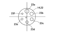
図2は、前記投影系開口絞り14、前記受光系開口絞り22を示しており、本実施の形態では前記投影系開口絞り14と前記受光系開口絞り22とは同一のものが用いられている。以下、投影系開口絞り14について説明する。
FIG. 2 shows the projection
該投影系開口絞り14は円板に6つの絞り孔23a,23b,23c,23d,23e,23fが穿設されたものであり、該絞り孔23a,23b,23c,23d,23e,23fは同一円周上の6等分した位置に設けられ、孔径は瞳の大きさを考慮してφ1mm〜φ8mm程度となっている。例えば、φ1mm、φ2mm、φ3mm、φ4mm、φ5mm、φ6mmが選択される。
The projection
前記投影系開口絞り14、前記受光系開口絞り22は回転可能に設けられ、前記絞り孔23a,23b,23c,23d,23e,23fの中心が前記投影光学系2の光軸、前記受光光学系3の光軸に合致する様になっている。
The projection system aperture stop 14 and the light receiving
前記投影系開口絞り14、前記受光系開口絞り22は例えばステッピングモータ(図示せず)に取付けられ、該ステッピングモータが60°ずつ間欠回転することで前記絞り孔23a,23b,23c,23d,23e,23fの所要の絞り孔が選択される様になっている。又、それぞれのステッピングモータは後述する制御部28によって独立して制御される。前記絞り孔23a,23b,23c,23d,23e,23fの選択は、被検者の瞳径に合わせ選択され、又前記投影系開口絞り14で選択された絞り孔23の径と前記受光系開口絞り22で選択した絞り孔23の径を変えることで、例えば前記投影系開口絞り14で選択された絞り孔23の径に対し、前記受光系開口絞り22で選択した絞り孔23の径を小さく設定すると、前記光電検出器21で得られる画像からPTF(Phase Tranfer Function)が算出可能である。
The projection system aperture stop 14 and the light receiving
前記光電検出器21はCCD受光センサ等、受光面が画素の集合であり、受光信号に基づき受光面内での各画素の位置、受光面での像の形状等を検出可能となっている。各画素の位置、形状については、受光面上に座標を設定し、各画素の座標値を算出することで決定される。
The
前記光電検出器21からの受光信号は信号処理部26を介して記憶部27に記憶される。前記信号処理部26から前記記憶部27へのデータの書込みは制御部28によって制御され、該制御部28は上記した様に、駆動機構の制御を行うと共に眼光学特性演算手段として機能し、シミュレーション画像演算部と、視力演算部とを有し、前記記憶部27に記憶されたデータを基に所要の演算をし、又演算結果を表示部29に表示する。又、前記記憶部27には、測定を実行する為のシーケンスプログラム、前記光電検出器21からの信号に基づき受光像の状態を判定する受光画像判定プログラム、前記光電検出器21からの受光信号を基に眼光学特性の演算を行う演算プログラム等が格納されている。
The received light signal from the
以下、上記光学系の作用について説明する。 Hereinafter, the operation of the optical system will be described.
前記被検眼1に前記固視標15を注視させた状態で、前記投影光学系2により投影光束を投影する。尚、前記固視標15に関しては可視光が用いられ、前記投影光束については赤外光が用いられる。
A projection light beam is projected by the projection
前記光源5から発せられた投影光束(赤外光)は、前記リレーレンズ6、ハーフミラー7を透過し、透過した投影光束は前記開口絞り14により光束径が決定され、前記偏光ビームスプリッタ8に至り、該偏光ビームスプリッタ8でS直線偏光分が反射され、前記リレーレンズ9を経て前記対物レンズ11により前記1/4波長板13を経て前記被検眼1の眼底に投影され、点像として第1次視標像が結像される。
The projected light beam (infrared light) emitted from the
S直線偏光が前記1/4波長板13を透過することで、右円偏光となる。前記被検眼1の眼底で投影光束が反射され、反射光束は眼底で反射されることで、左円偏光となる。更に、反射光束が前記1/4波長板13を透過することで、前記S直線偏光とは偏光方向が90°異なるP直線偏光となる。
When the S linearly polarized light is transmitted through the
P直線偏光は、前記対物レンズ11、リレーレンズ9により前記偏光ビームスプリッタ8に導かれる。該偏光ビームスプリッタ8はS直線偏光を反射し、P直線偏光を透過するので、前記反射光束は該偏光ビームスプリッタ8を透過し、前記受光系開口絞り22により受光光束径が決定される。該受光系開口絞り22を通過した反射光束は前記合焦レンズ19、結像レンズ20により前記光電検出器21上に第2次視標像として結像される。
P linearly polarized light is guided to the polarization beam splitter 8 by the
該光電検出器21が受光した第2次視標像の光量強度分布は前記被検眼1の眼光学特性を反映しており、前記光電検出器21の受光状態を検出することで、眼光学特性を測定することができる。
The light intensity distribution of the secondary target image received by the
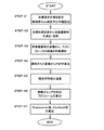
次に、図3を参照して眼光学特性を測定する為の作動について説明する。 Next, the operation for measuring the eye optical characteristics will be described with reference to FIG.
STEP:01 被検眼のディオプター値(以下度数(D))に対応して目標位置を設定する。被検眼の度数については、他の測定器によって事前に測定された値が使用される。目標設定は、前記光源部4、合焦レンズ19を手動で移動して行われる。尚、度数については本装置で測定して得られた度数の位置に自動的に設定される様にしてもよい。
STEP: 01 A target position is set corresponding to the diopter value (hereinafter, frequency (D)) of the eye to be examined. A value measured in advance by another measuring device is used for the power of the eye to be examined. The target setting is performed by manually moving the light source unit 4 and the focusing
STEP:02 STEP:01で設定した位置を含めて、目標位置の前後複数の位置、例えば0.03Dのステップで移動させ、ステップ毎の視標像について前記光電検出器21からの受光信号から複数枚の画像を取得する。
STEP: 02 A plurality of positions before and after the target position including the position set in STEP: 01, for example, a step of 0.03D, are moved from the received light signal from the
STEP:03 取得した複数の画像から、画像の図形を基に焦点の状態が判断され、受光された視標像のベストフォーカス位置が求められ、ベストフォーカス位置の画像が選択される。 (Step 03) From the acquired images, the focus state is determined based on the graphic of the image, the best focus position of the received target image is obtained, and the image at the best focus position is selected.
STEP:04,05 選択された画像について、PSF等眼光学特性が演算される。 (Steps 04, 05) The PSF iso-optical characteristics are calculated for the selected image.
STEP:06 視標ギャップ方向のプロフィールが演算される。 STEP: 06 The target gap direction profile is calculated.
STEP:07 更に、Depression値、Contrast値が演算される。演算されたDepression値、Contrast値は、前記表示部29に表示される。
(Step 07) Further, a Depression value and a Contrast value are calculated. The calculated Depression value and Contrast value are displayed on the
ここで、STEP:04、STEP:05、STEP:06、STEP:07に於けるPSF等の眼光学特性、視標ギャップ方向のプロフィール、Depression値、Contrast値の演算については、本出願人が既に出願した、特願2000−364834(特開2002−209852号公報)(特許文献2)に於いて説明されている。 Here, regarding the calculation of eye optical characteristics such as PSF, target gap direction profile, Depression value, and Contrast value in STEP: 04, STEP: 05, STEP: 06, STEP: 07 This is described in Japanese Patent Application No. 2000-364834 (Japanese Patent Laid-Open No. 2002-209852) (Patent Document 2) filed.
又、STEP:03に於ける視標像のベストフォーカス位置が求められる。図4により、ベストフォーカス位置の画像が選択される作用について説明する。 Further, the best focus position of the target image in STEP: 03 is obtained. The operation of selecting the image at the best focus position will be described with reference to FIG.
STEP:301,302 取得した複数の画像から各画像に於ける最高輝度値を算出し、各最高輝度値が第1スライスレベル以上である画像が選択される。選択された画像は、例えば図5(A)〜図5(J)に示される。 (Steps 301 and 302) The highest luminance value in each image is calculated from the plurality of acquired images, and an image having each highest luminance value equal to or higher than the first slice level is selected. The selected image is shown in FIGS. 5A to 5J, for example.
STEP:303 STEP:302で選択された画像の中から最高輝度値が最も高い画像が選択される。 STEP: 303 An image having the highest maximum luminance value is selected from the images selected in STEP: 302.
STEP:304,305 STEP:303で選択された画像が1枚かどうかが判断され、1枚である場合は、該画像について第1スライスレベル以上の輝度値を示している画素数が求められる。
(
STEP:306,307 STEP:305で得られた画素が形成する形状について、例えば、直交する2方向の大きさで形状の判断が行われる。例えば、前記光電検出器21の受光面の座標上で水平、垂直方向で略同等な大きさになっているかが判断され、略同等な大きさと判断された場合は、STEP:303で選択された1枚の画像が演算対象画像(測定画像)として選択される。例えば、図5(F)が選択される。
STEP: 306, 307 For the shape formed by the pixel obtained in STEP: 305, for example, the shape is determined based on the size in two orthogonal directions. For example, it is determined whether or not the size is approximately equal in the horizontal and vertical directions on the coordinates of the light receiving surface of the
STEP:308 次に、STEP:306に於いて、画素の形成する形状が、水平、垂直方向で略同等な大きさとなっていない場合、STEP:305で選択された画像の前後の画像について、それぞれ第1スライスレベル以上の画素数が求められる。 STEP: 308 Next, in STEP: 306, when the shapes formed by the pixels are not substantially the same size in the horizontal and vertical directions, for the images before and after the image selected in STEP: 305, respectively. The number of pixels equal to or higher than the first slice level is obtained.
STEP:309 STEP:308で得られた画素が形成する形状の判断が行われる。受光面の座標上で水平、垂直方向の大きさが求められ、水平、垂直方向の大きさから形状が判断される。例えば、形状を判断するものとして、水平、垂直方向の大きさの比が求められる。 STEP: 309 The shape formed by the pixel obtained in STEP: 308 is determined. The horizontal and vertical sizes are obtained on the coordinates of the light receiving surface, and the shape is determined from the horizontal and vertical sizes. For example, the ratio of the sizes in the horizontal and vertical directions is determined as the shape determination.
STEP:310 選択された各画像それぞれについて、水平、垂直方向の大きさが最も近いもの、例えば求められた比が最も1に近いものが演算対象画像として決定される。 (Step 310) For each of the selected images, the image having the closest horizontal and vertical sizes, for example, the image having the calculated ratio closest to 1, is determined as the calculation target image.
更に、STEP:303で選択された画像が複数枚ある場合は、STEP:311の以降の作用により、演算対象画像が決定される。 Furthermore, when there are a plurality of images selected in STEP: 303, the calculation target image is determined by the subsequent operation of STEP: 311.
STEP:311 選択された複数の画像それぞれについて、第1スライスレベル以上の画素数が求められる。 (Step 311) For each of the plurality of selected images, the number of pixels equal to or higher than the first slice level is obtained.
STEP:312 画素数が一番少ない画像が選択される。 (Step 312) The image having the smallest number of pixels is selected.
STEP:313,314 選択された画像で、第1スライスレベル以上の画素が形成する形状について、座標上で水平、垂直方向で略同等な大きさになっているかが判断され、略同等な大きさと判断された場合は、STEP:312で選択された1枚の画像が演算対象画像として決定される。
(
STEP:315,316 STEP:312で選択された画像に関し、第1スライスレベル以上の画素が形成する形状が、水平、垂直方向で略同等な大きさでない場合、STEP:312で得られた前後の画像について第1スライスレベル以上の画素数が求められ、更に画素が形成する形状について、座標上で水平、垂直方向の大きさが求められ、水平、垂直方向の大きさから形状が判断される。 STEP: 315, 316 For the image selected in STEP: 312, if the shapes formed by the pixels of the first slice level or higher are not substantially the same size in the horizontal and vertical directions, the images before and after obtained in STEP: 312 The number of pixels equal to or higher than the first slice level is obtained for the image, and the horizontal and vertical sizes are determined on the coordinates for the shape formed by the pixels, and the shape is determined from the horizontal and vertical sizes.
STEP:317 選択された各画像それぞれについて、水平、垂直方向の大きさが最も近いものが演算対象画像として決定される。 (Step 317) For each of the selected images, the closest image in the horizontal and vertical directions is determined as the calculation target image.
上述した、画像の判断により、フォーカス状態が最もよく、更に最も最小錯乱円に近い画像が演算対象画像として選択される。従って、演算対象画像の選択に検者の個人差による影響が排除される。 Based on the above-described image determination, an image having the best focus state and closest to the minimum circle of confusion is selected as the calculation target image. Therefore, the influence of the individual difference of the examiner on selection of the calculation target image is eliminated.
選択された画像は、前記表示部29に表示され、検者により確認され、STEP:04に於いてPSF等眼光学特性が演算され、或は選択されると直ちに演算が実行される。
The selected image is displayed on the
尚、STEP:306,309,316等の座標上での水平、垂直方向の大きさの判断は、様々な方法で判断可能である。上述の選択された画像中の第1スライスレベル以上の画素が形成する形状について水平、垂直方向の大きさを比較する方法のみではなく、例えば画素が形成する画像の重心位置を求め、該重心位置を中心として形状の長径及び短径を比較する方法(画素による形状を楕円と近似してもよいし、しなくてもよい)を用いてもよい。 Note that the horizontal and vertical sizes on the coordinates of STEP: 306, 309, 316, etc. can be determined by various methods. In addition to the method of comparing the horizontal and vertical sizes of the shape formed by the pixels at the first slice level or higher in the selected image, for example, the centroid position of the image formed by the pixels is obtained and the centroid position is determined. A method of comparing the major axis and the minor axis of the shape centering on the pixel (the shape of the pixel may or may not be approximated to an ellipse) may be used.
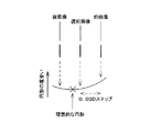
又、図6に示す様に選択された1枚の画像とその前後の画像の3枚各々についての画素が形成する形状の水平、垂直方向の大きさの比較から、最小錯乱円がより理想的な円形になるであろうディオプター値を求めることができる。従って、選択された1枚の画像が理想的な円形からずれている場合は、再度測定することも可能である。この時、円形の度合いに閾値等を設けることにより自動で行うこともできる。その際に、該ディオプター値により測定するだけでなく、その前後のディオプター値を含めて先の測定と同様に複数枚測定し、再度選択することもできる。これにより、検者の個人差により左右されず、更に測定精度を向上することができる。 Also, as shown in FIG. 6, the minimum circle of confusion is more ideal from the comparison of the horizontal and vertical sizes of the shapes formed by the pixels for each of the selected image and the preceding and succeeding images. The diopter value that would be a perfect circle can be determined. Therefore, when one selected image deviates from an ideal circle, it can be measured again. At this time, it can be automatically performed by providing a threshold value or the like for the degree of circularity. At that time, not only by the diopter value, but also by measuring a plurality of sheets including the diopter values before and after the diopter value and selecting them again. Thereby, it is not influenced by the individual difference of the examiner, and the measurement accuracy can be further improved.
1 被検眼
2 投影光学系
3 受光光学系
5 光源
15 固視標
17 固視標系
19 合焦レンズ
21 光電検出器
26 信号処理部
27 記憶部
28 制御部
DESCRIPTION OF
Claims (2)
Priority Applications (1)
| Application Number | Priority Date | Filing Date | Title |
|---|---|---|---|
| JP2005070381A JP4598570B2 (en) | 2005-03-14 | 2005-03-14 | Ophthalmic optical characteristic measuring device |
Applications Claiming Priority (1)
| Application Number | Priority Date | Filing Date | Title |
|---|---|---|---|
| JP2005070381A JP4598570B2 (en) | 2005-03-14 | 2005-03-14 | Ophthalmic optical characteristic measuring device |
Publications (2)
| Publication Number | Publication Date |
|---|---|
| JP2006247234A JP2006247234A (en) | 2006-09-21 |
| JP4598570B2 true JP4598570B2 (en) | 2010-12-15 |
Family
ID=37088303
Family Applications (1)
| Application Number | Title | Priority Date | Filing Date |
|---|---|---|---|
| JP2005070381A Expired - Fee Related JP4598570B2 (en) | 2005-03-14 | 2005-03-14 | Ophthalmic optical characteristic measuring device |
Country Status (1)
| Country | Link |
|---|---|
| JP (1) | JP4598570B2 (en) |
Families Citing this family (1)
| Publication number | Priority date | Publication date | Assignee | Title |
|---|---|---|---|---|
| JP5038703B2 (en) * | 2006-12-22 | 2012-10-03 | 株式会社トプコン | Ophthalmic equipment |
Family Cites Families (8)
| Publication number | Priority date | Publication date | Assignee | Title |
|---|---|---|---|---|
| JP2000116602A (en) * | 1998-10-09 | 2000-04-25 | Canon Inc | Fundus camera |
| JP2001095760A (en) * | 1999-09-28 | 2001-04-10 | Topcon Corp | Eye optical characteristics measurement device |
| JP2001120503A (en) * | 1999-10-27 | 2001-05-08 | Ryusyo Industrial Co Ltd | Cornea shape measuring device |
| JP4606560B2 (en) * | 2000-10-10 | 2011-01-05 | 株式会社トプコン | Ophthalmic optical characteristic measuring device |
| JP4598261B2 (en) * | 2000-11-16 | 2010-12-15 | 株式会社トプコン | Ophthalmic optical characteristic measuring device |
| JP2003070741A (en) * | 2001-09-05 | 2003-03-11 | Topcon Corp | Eye optical characteristics measuring device |
| JP3821720B2 (en) * | 2002-02-15 | 2006-09-13 | 株式会社トプコン | Ophthalmic optical characteristic measuring device |
| JP2003235802A (en) * | 2002-02-15 | 2003-08-26 | Topcon Corp | Eye optical characteristics measuring device |
-
2005
- 2005-03-14 JP JP2005070381A patent/JP4598570B2/en not_active Expired - Fee Related
Also Published As
| Publication number | Publication date |
|---|---|
| JP2006247234A (en) | 2006-09-21 |
Similar Documents
| Publication | Publication Date | Title |
|---|---|---|
| JP5199031B2 (en) | Ophthalmic imaging equipment | |
| JP5340693B2 (en) | Ophthalmic imaging equipment | |
| JP5355994B2 (en) | Ophthalmic imaging equipment | |
| JP6354979B2 (en) | Fundus photographing device | |
| JP4598261B2 (en) | Ophthalmic optical characteristic measuring device | |
| US9687143B2 (en) | Ophthalmic photography device, ophthalmic photography method, and ophthalmic photography program | |
| JP6853496B2 (en) | Optometry device and optometry program | |
| JP2015085044A (en) | Ophthalmology imaging apparatus, ophthalmology imaging system, and ophthalmology imaging program | |
| JP7459491B2 (en) | Ophthalmology measuring device | |
| US12440097B2 (en) | OCT device | |
| JP4684700B2 (en) | Ophthalmic optical characteristic measuring device | |
| JPH11104082A (en) | Ophthalmic device | |
| JP2015085043A (en) | Fundus photographing device | |
| JP6421919B2 (en) | Ophthalmic imaging equipment | |
| JP4630126B2 (en) | Ophthalmic optical characteristic measuring device | |
| JP6853495B2 (en) | Subjective optometry device and subjective optometry program | |
| JP4598570B2 (en) | Ophthalmic optical characteristic measuring device | |
| JP7035630B2 (en) | Ophthalmic equipment | |
| JP2016049368A (en) | Ophthalmological photographing apparatus | |
| JP2009207572A (en) | Fundus camera | |
| JP4731989B2 (en) | Ophthalmic optical characteristic measuring device | |
| JP6454090B2 (en) | Eye refractive power measuring device | |
| JP5787060B2 (en) | Fundus photographing device | |
| JP5329422B2 (en) | Ophthalmic examination equipment | |
| JP2017051429A (en) | Ophthalmic apparatus, control method therefor, and program |
Legal Events
| Date | Code | Title | Description |
|---|---|---|---|
| A621 | Written request for application examination |
Free format text: JAPANESE INTERMEDIATE CODE: A621 Effective date: 20080111 |
|
| TRDD | Decision of grant or rejection written | ||
| A01 | Written decision to grant a patent or to grant a registration (utility model) |
Free format text: JAPANESE INTERMEDIATE CODE: A01 Effective date: 20100914 |
|
| A01 | Written decision to grant a patent or to grant a registration (utility model) |
Free format text: JAPANESE INTERMEDIATE CODE: A01 |
|
| A61 | First payment of annual fees (during grant procedure) |
Free format text: JAPANESE INTERMEDIATE CODE: A61 Effective date: 20100924 |
|
| R150 | Certificate of patent or registration of utility model |
Ref document number: 4598570 Country of ref document: JP Free format text: JAPANESE INTERMEDIATE CODE: R150 Free format text: JAPANESE INTERMEDIATE CODE: R150 |
|
| FPAY | Renewal fee payment (event date is renewal date of database) |
Free format text: PAYMENT UNTIL: 20131001 Year of fee payment: 3 |
|
| R250 | Receipt of annual fees |
Free format text: JAPANESE INTERMEDIATE CODE: R250 |
|
| R250 | Receipt of annual fees |
Free format text: JAPANESE INTERMEDIATE CODE: R250 |
|
| R250 | Receipt of annual fees |
Free format text: JAPANESE INTERMEDIATE CODE: R250 |
|
| R250 | Receipt of annual fees |
Free format text: JAPANESE INTERMEDIATE CODE: R250 |
|
| R250 | Receipt of annual fees |
Free format text: JAPANESE INTERMEDIATE CODE: R250 |
|
| R250 | Receipt of annual fees |
Free format text: JAPANESE INTERMEDIATE CODE: R250 |
|
| LAPS | Cancellation because of no payment of annual fees |