JP4598283B2 - Decorative plate mounting structure - Google Patents
Decorative plate mounting structure Download PDFInfo
- Publication number
- JP4598283B2 JP4598283B2 JP2001035022A JP2001035022A JP4598283B2 JP 4598283 B2 JP4598283 B2 JP 4598283B2 JP 2001035022 A JP2001035022 A JP 2001035022A JP 2001035022 A JP2001035022 A JP 2001035022A JP 4598283 B2 JP4598283 B2 JP 4598283B2
- Authority
- JP
- Japan
- Prior art keywords
- decorative plate
- decorative
- mounting structure
- plate
- latching
- Prior art date
- Legal status (The legal status is an assumption and is not a legal conclusion. Google has not performed a legal analysis and makes no representation as to the accuracy of the status listed.)
- Expired - Fee Related
Links
Images


Description
【0001】
【発明の属する技術分野】
この発明は、システムキッチンなど厨房家具の側面を覆う化粧板の取付構造に関するものであり、詳しくはワークトップの側面とベースキャビネットの側板を覆う化粧板の取付構造に関するものである。
【0002】
【従来の技術】
一般的にシステムキッチンは複数のベースキャビネット上に、シンクを一体とするか或いは別途シンクを取り付けるようにしたワークトップを載置固定する構造となっている。
出願人は、図8に示すようにワ一クトップのバックガード及び左右のサイドガードを206mm程度となるよう特別に高く構成しバックガードに小物掛けや収納ポケットを一体に形成し、ワ一クトップの機能性と水仕舞いの向上を図ったシステムキッチンを提供した。
【0003】
このようなシスムキッチンでは、サイドガードの裏側となる外側面とベースキャビネット側板が室内に露出する配置となりがちで、この場合美感上好ましくないため、ここを全体として化粧板で覆う手段が取られている。
その手段として、出願人は図9、図10のように化粧板10をべ一スキャビネット20とワークトップのサイドガード30にあてがい固定する手段を採用していた。
すなわち、化粧板10の上部にはZ型をなし、ビスによる取付片50aと化粧板10と間隔をもった引掛片50bとからなる掛止金具50、50を設けるようにする。一方、ステンレス製のサイドガード30の上端は平坦面及び垂下面により逆コ字状に折曲してあり、垂下片の内面に掛止金具50の引掛片50bが入り込むように化粧板10を傾けて潜り込ませ(図9)てから、化粧板10を垂直に立ち上がらせ、次いでベースキャビネット20の内側から化粧板10に達するビス60をねじ込むことで固定していた。
【0004】
【発明が解決しようとする課題】
化粧板10を傾けて引掛片50bを変形させつつ入り込ませるようにするので、化粧板10とサイドガード30に隙間が生じがちとなり、ビス60によってベースキャビネット20と化粧板10をねじ込み固定すると、化粧板10上部が離反するように外側に反りがちで、隙間を大きくするという不都合が生じていた。
【0005】
また、施工現場における要請は、キッチンの前面側から化粧板10を傾けることなく垂直に立てた状態のままで壁に向かって押し込み取り付けできることであった。
その理由は、例えば図8の右側に殆ど隙間がなく内壁などが存在すれば化粧板10を傾けて掛止金具50の引掛片50bをサイドガード30に入り込ませることができなくなるからである。
また、特に図7に示すように、化粧板を長尺としてウォールキャビネットの側面を含めて天井にまで達するようなサイズのものを採用しようとすると、壁面上部のウォールキャビネットにぶつかって化粧板を傾ける余地がなく取り付けできないからである。
【0006】
【課題を解決するための手段】
本発明は、以上のようなサイドガードの高い厨房家具の側面を覆う化粧板の固定手段を改良することを目的とし、更にワークトップのサイドガードが高いシステムキッチンに好適で、取り付け作業性の良い化粧板の取付構造を提供しようとするものである。
【0007】
請求項1の発明の要旨とするのは、厨房家具におけるワークトップのサイドガードとべースキャビネットの側面に垂直にあてがう化粧板であって、化粧板とワークトップのサイドガードの対応箇所には、夫々互いに掛け外し自在な掛止部及び被掛止部からなる掛止手段を設け、別途ベースキャビネットの側板と化粧板をビス等の固着具で固定する取付構造において、掛止手段の掛止部を、化粧板表面に添う取付片及びこれと一体にして突出すると共に左右に折り起してなる翼片とからなる掛止具を複数とし、被掛止部を、ワークトップをステンレス鋼板を折曲して平坦面及び垂下面を形成するものとして垂下面の開放端に掛止具の翼片の入り込むスロットにより構成し、掛止具の翼片はサイドガード上部内をスライドして掛止することができるようにしたことを特徴とするものである。
【0008】
請求項2の発明の要旨とするのは、被掛止部のスロットを垂下片の開放端につながる門型としたことを特徴とするものであり、請求項3の発明の要旨とするのは、被掛止部のスロットを垂下面に窓型として形成したことを特徴とするものである。
【0009】
請求項3の発明は、化粧板を高くしてベースキャビネットからウォールキャビネットの側面までを一体に覆うものとし、ウオールキャビネットの側板と化粧板をビスなどの固着具により固定することを特徴とするものである。
【0010】
【発明の実施の形態】
以下、図面に示す実施の形態に即して本発明を説明する。
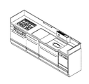
図1乃至図4は、化粧板1を食器洗浄乾燥機を収蔵した機器収納用ベースキャビネット2の側面板21とステンレス鋼板にて形成したワークトップWのサイドガード3の側面部を覆うように取り付けた状態を示すものである。
この化粧板1は、図2に示すように高さはサイドガード3上部までとほぼ一致するか若干(10mm)程度高くしてあるが、並列させたベースキャビネット群の奥行きよりも長くしてある。片開きの扉でなく機器収納用ベースキャビネット2を引き出し式としてあるので支障はない。
【0011】
化粧板1は、むくの木製或いは周囲及び中に補強板を配して肉薄の合板を貼ったサンドイッチ構造のものとする。
この化粧板1のサイドガード3の上部にあてがう側の表面に設ける掛止部4は、図示の実施例では金属にて一体に形成した二つの掛止具5、5にて形成するようにしている。
掛止具5(図3a〜図3c参照)は、化粧板1の片面に添わせる矩形の取付片51とサイドガード3の上部内にスライドして入り込む翼片52とからなる。
取付片51はビス6にて化粧板1にねじ込むもので、微調整可能なように縦方向に長いビス用穴51aを一対設けてある。
翼片52は、サイドガード3側に突出するように連設し、さらに左右に折り起してなるものである。
【0012】
サイドガード3側の被掛止部7は、図示の例ではサイドガード3自体にて構成するようにしてある。
すなわち、サイドガード3上端を外側に断面コ型になるように平坦面31、垂下面32というように屈曲して逆溝形とし、下向きの垂下面32の開放端につながり掛止具5の翼片52の入り込む二つの門型のスロット32a、32aを設けて構成している。スロット32a、32aは門型(下方が開放しているという意)であれば形状は問わない。
化粧板1に取り付けた掛止具5の翼片52をスロット32a、32aと合致させるように入り込ませ化粧板1とサイドガード3の垂下面32外側とを添わせ、次いで化粧板1自体を奥へスライドさせて翼片52がサイドガード3の垂下面32の内面に添うように潜り込ませる。このようにして化粧板1をサイドガード3に連結する。
あとは、機器収納用ベースキャビネット2の側面板21の内側からビス等の固着具を化粧板1までねじ込み固定することになる。
【0013】
掛止具5及び被掛止部7の配置箇所は、図2に示すように化粧板1を垂直に立ててベースキャビネット2の手前側の位置で入り込ませ、機器収納用ベースキャビネット2の背面側に押し込むようにスライドさせることで連結するようにすれば、予め機器収納用ベースキャビネット2などのベースキャビネット群を壁面に沿って設置固定しておいても簡単に取り付けることができることになる。
【0014】
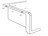
図5、図6は被掛止部7の別の実施態様を示すもので、スロット32a、32aを垂下面32に窓穴として構成したものを示すものである。
このような構成とすることもできるが、掛止具5の取り付け位置や施工現場での作業精度が要求されることになる。この場合はスライドさせて潜り込ませる側の翼片52を長くして垂下面32の内面への接合面積を広げれば、二つの掛止具5、5で十分な掛止手段となる。
【0015】
図7は、厨房家具としてのベースキャビネット及びサイドガードのみならず上部に延長してウォールキャビネット8の側面までの長さの化粧板1について適用した例である。
基本的な構成は図1乃至図6に示したものと同一であるので説明は省略する。この化粧板1の上部は図示しないが、ウォールキャビネット8の内側からビス止めすることで固定する。
このように化粧板1が床面から天井に至る長さであると、従来の手段では化粧板1を傾けなければならないのでサイドガードと化粧板を掛止手段により繋げることはできなかった。
【0016】
【発明の効果】
請求項1乃至請求項4の発明では、キッチンの前面側から化粧板を傾けることなく直立させたままで掛止部を被掛止部に入り込ませスライドさせることで、化粧板をサイドガードに掛止することができるので、掛止部や被掛止部は取り付け作業に際して変形することがなく、最少の隙間でも取り付け可能で、しかも作業性が良好となる。
請求項2の発明では、スロットを下向きに開放した構成としたため、掛止具を入れ込み易く、上下の取付位置の制約を緩和できる。
請求項4の発明では、化粧板が長尺でウォールキャネットにより傾ける余地がない場合従来の掛止手段では対応できなかったのを可能としたことになる。
【図面の簡単な説明】
【図1】この発明に係る化粧板の取付方法を示す斜視図である。
【図2】化粧板を想像線で示す取付状態の側面図である。
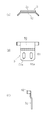
【図3】a〜cは掛止具の夫々平面図、正面図、側面図である。
【図4】取付状態の斜視図である。
【図5】別の実施形態を示すサイドガードの斜視図である。
【図6】取付方法を示す斜視図である。
【図7】さらに別の実施形態を示すもので、長い化粧板とした場合の取付状態の斜視図である。
【図8】従来例の斜視図である。
【図9】取り付け方法を示す要部斜視図である。
【図10】化粧板とキャビネットの固定手段を示す概略斜視図である。
【符号の説明】
1 化粧板
2 機器収納用ベースキャビネット
3 サイドガード
31 平坦面
32 垂下面
32a スロット
4 掛止部
5 掛止具
6 ビス
7 被掛止部[0001]
BACKGROUND OF THE INVENTION
The present invention relates to a structure for attaching a decorative plate that covers a side surface of a kitchen furniture such as a system kitchen, and more particularly to a structure for attaching a decorative plate that covers a side surface of a worktop and a side plate of a base cabinet.
[0002]
[Prior art]
In general, the system kitchen has a structure in which a work top having a sink integrated or a separate sink is placed and fixed on a plurality of base cabinets.
As shown in FIG. 8, the applicant configures the back guard of the work top and the left and right side guards to be particularly high so as to be about 206 mm, and the back guard is integrally formed with a small item hook and a storage pocket. A system kitchen with improved functionality and water performance was provided.
[0003]
In such a system kitchen, the outer side surface and the base cabinet side plate, which are the back side of the side guard, tend to be exposed in the room. Yes.
As the means, the applicant has adopted means for fixing the
That is, the upper part of the
[0004]
[Problems to be solved by the invention]
Since the
[0005]
Moreover, the request | requirement in a construction site was that it can push in and attach toward a wall in the state which stood up vertically without tilting the
The reason is, for example, because hardly able to enter the
In particular, as shown in FIG. 7, if a decorative plate is used as a long size and reaches the ceiling including the side of the wall cabinet, the decorative plate is tilted by hitting the wall cabinet at the top of the wall surface. This is because there is no room for installation.
[0006]
[Means for Solving the Problems]
The object of the present invention is to improve the fixing means of the decorative plate that covers the side of the kitchen furniture having a high side guard as described above, and is suitable for a system kitchen having a high work side guard and has a good workability. It is an object of the present invention to provide a decorative plate mounting structure.
[0007]
The gist of the invention of
[0008]
The gist of the invention of
[0009]
The invention of
[0010]
DETAILED DESCRIPTION OF THE INVENTION
The present invention will be described below with reference to embodiments shown in the drawings.
1 to 4, the
As shown in FIG. 2, the
[0011]
The
The
The latch 5 (see FIGS. 3 a to 3 c) includes a
The
The
[0012]
The hooked portion 7 on the
In other words, the upper end of the
The
After that, a fixing tool such as a screw is screwed and fixed to the
[0013]
As shown in FIG. 2, the arrangement place of the
[0014]
FIG. 5 and FIG. 6 show another embodiment of the hooked portion 7, in which the
Although it can also be set as such a structure, the attachment position of the
[0015]
FIG. 7 shows an example in which the
Since the basic configuration is the same as that shown in FIGS. 1 to 6, description thereof will be omitted. Although the upper part of this
When the
[0016]
【The invention's effect】
In the first to fourth aspects of the invention, the decorative plate is latched on the side guard by sliding the latching portion into the latched portion while keeping the decorative plate upright from the front side of the kitchen without being inclined. Therefore, the hooking portion and the hooked portion are not deformed during the mounting operation, can be mounted with a minimum gap, and workability is improved.
In the invention of
In the invention of
[Brief description of the drawings]
FIG. 1 is a perspective view showing a method of attaching a decorative board according to the present invention.
FIG. 2 is a side view of an attachment state in which a decorative board is indicated by an imaginary line.
FIGS. 3A to 3C are a plan view, a front view, and a side view, respectively, of a latching tool.
FIG. 4 is a perspective view of an attached state.
FIG. 5 is a perspective view of a side guard showing another embodiment.
FIG. 6 is a perspective view showing an attachment method.
FIG. 7 is a perspective view of an attached state when a long decorative board is shown, showing still another embodiment.
FIG. 8 is a perspective view of a conventional example.
FIG. 9 is a perspective view of a main part showing an attachment method.
FIG. 10 is a schematic perspective view showing a fixing means for a decorative plate and a cabinet.
[Explanation of symbols]
DESCRIPTION OF
Claims (4)
掛止手段の掛止部を、化粧板表面に添う取付片及びこれと一体にして突出すると共に左右に折り起してなる翼片とからなる掛止具を複数とし、被掛止部を、ワークトップをステンレス鋼板を折曲して平坦面及び垂下面を形成するものとして垂下面の開放端に掛止具の翼片の入り込むスロットにより構成し、掛止具の翼片はサイドガード上部内をスライドして掛止することができるようにしたことを特徴とする化粧板の取付構造。A decorative plate that is applied perpendicularly to the sides of the worktop side guard and the base cabinet in kitchen furniture, and the corresponding portions of the decorative plate and the side guard of the worktop are respectively detachable hooks and hooks that are freely detachable from each other. In the mounting structure that provides the latching means consisting of the stopper, and separately fixes the side plate of the base cabinet and the decorative plate with a fastener such as a screw,
The latching portion of the latching means has a plurality of latching tools composed of a mounting piece that follows the decorative plate surface and a wing piece that projects integrally with the mounting piece and folds to the left and right. The work top is made of a stainless steel plate that is bent to form a flat surface and a hanging surface. The work top is composed of a slot into which the wing piece of the hanging tool enters the open end of the hanging surface. A decorative plate mounting structure characterized in that it can be slid and latched.
Priority Applications (1)
| Application Number | Priority Date | Filing Date | Title |
|---|---|---|---|
| JP2001035022A JP4598283B2 (en) | 2001-02-13 | 2001-02-13 | Decorative plate mounting structure |
Applications Claiming Priority (1)
| Application Number | Priority Date | Filing Date | Title |
|---|---|---|---|
| JP2001035022A JP4598283B2 (en) | 2001-02-13 | 2001-02-13 | Decorative plate mounting structure |
Publications (3)
| Publication Number | Publication Date |
|---|---|
| JP2002233425A JP2002233425A (en) | 2002-08-20 |
| JP2002233425A5 JP2002233425A5 (en) | 2008-03-27 |
| JP4598283B2 true JP4598283B2 (en) | 2010-12-15 |
Family
ID=18898528
Family Applications (1)
| Application Number | Title | Priority Date | Filing Date |
|---|---|---|---|
| JP2001035022A Expired - Fee Related JP4598283B2 (en) | 2001-02-13 | 2001-02-13 | Decorative plate mounting structure |
Country Status (1)
| Country | Link |
|---|---|
| JP (1) | JP4598283B2 (en) |
Families Citing this family (6)
| Publication number | Priority date | Publication date | Assignee | Title |
|---|---|---|---|---|
| DE102005028514A1 (en) * | 2005-06-17 | 2006-12-28 | Zf Friedrichshafen Ag | Pedal arrangement for a motor vehicle |
| JP5672553B2 (en) * | 2011-08-24 | 2015-02-18 | パナソニックIpマネジメント株式会社 | Equipment mounting structure |
| WO2019207683A1 (en) * | 2018-04-25 | 2019-10-31 | 三菱電機株式会社 | Air conditioner outdoor unit |
| JP7271068B2 (en) | 2019-09-10 | 2023-05-11 | クリナップ株式会社 | cabinet |
| JP7366508B2 (en) | 2020-07-31 | 2023-10-23 | クリナップ株式会社 | cabinet |
| JP7443215B2 (en) | 2020-10-06 | 2024-03-05 | 株式会社オカムラ | Storage fixtures and decorative boards |
Citations (3)
| Publication number | Priority date | Publication date | Assignee | Title |
|---|---|---|---|---|
| JPH02132454U (en) * | 1989-04-10 | 1990-11-02 | ||
| JPH07244A (en) * | 1993-06-15 | 1995-01-06 | Matsushita Electric Works Ltd | Structure for fitting decorative end panel to furniture |
| JP2001149149A (en) * | 1999-11-29 | 2001-06-05 | Hitachi Chem Co Ltd | Kitchen cabinet |
-
2001
- 2001-02-13 JP JP2001035022A patent/JP4598283B2/en not_active Expired - Fee Related
Patent Citations (3)
| Publication number | Priority date | Publication date | Assignee | Title |
|---|---|---|---|---|
| JPH02132454U (en) * | 1989-04-10 | 1990-11-02 | ||
| JPH07244A (en) * | 1993-06-15 | 1995-01-06 | Matsushita Electric Works Ltd | Structure for fitting decorative end panel to furniture |
| JP2001149149A (en) * | 1999-11-29 | 2001-06-05 | Hitachi Chem Co Ltd | Kitchen cabinet |
Also Published As
| Publication number | Publication date |
|---|---|
| JP2002233425A (en) | 2002-08-20 |
Similar Documents
| Publication | Publication Date | Title |
|---|---|---|
| US5222611A (en) | Wall-unit hanging system | |
| US5626404A (en) | Work space management system and cabinet therefor | |
| US5106173A (en) | Work space management system and cabinet therefor | |
| EP2146615B1 (en) | Under-counter mounting system for a dishwasher, and associated method | |
| JP4598283B2 (en) | Decorative plate mounting structure | |
| US20050246989A1 (en) | Backsplash assembly and method | |
| US20220265043A1 (en) | Portable cabinet | |
| JP5691888B2 (en) | Towel rack | |
| JP2003164347A (en) | Storage device for kitchen furniture | |
| JPH047788Y2 (en) | ||
| JPH0345616Y2 (en) | ||
| JPH0731717Y2 (en) | Kitchen cabinets | |
| JPH0352433Y2 (en) | ||
| JPS6035516B2 (en) | bay window | |
| JP2817459B2 (en) | Storage device | |
| JPH0666382U (en) | Kitchin unit | |
| JPS62106712A (en) | System kitchen | |
| KR20210112536A (en) | Kitchen shelf | |
| JP2003284612A (en) | Face-to-face kitchen unit | |
| JP3392100B2 (en) | Mounting structure of remote control transmitter for range hood operation | |
| JPS6112818Y2 (en) | ||
| JP2602223Y2 (en) | Kitchen shelves | |
| JPH10327956A (en) | Shelf board member for furniture | |
| JP5484312B2 (en) | Storage | |
| KR950000891Y1 (en) | Hanger for chopping board |
Legal Events
| Date | Code | Title | Description |
|---|---|---|---|
| A521 | Written amendment |
Free format text: JAPANESE INTERMEDIATE CODE: A523 Effective date: 20080212 |
|
| A621 | Written request for application examination |
Free format text: JAPANESE INTERMEDIATE CODE: A621 Effective date: 20080212 |
|
| A977 | Report on retrieval |
Free format text: JAPANESE INTERMEDIATE CODE: A971007 Effective date: 20081127 |
|
| TRDD | Decision of grant or rejection written | ||
| A01 | Written decision to grant a patent or to grant a registration (utility model) |
Free format text: JAPANESE INTERMEDIATE CODE: A01 Effective date: 20100831 |
|
| A01 | Written decision to grant a patent or to grant a registration (utility model) |
Free format text: JAPANESE INTERMEDIATE CODE: A01 |
|
| A61 | First payment of annual fees (during grant procedure) |
Free format text: JAPANESE INTERMEDIATE CODE: A61 Effective date: 20100924 |
|
| R150 | Certificate of patent or registration of utility model |
Free format text: JAPANESE INTERMEDIATE CODE: R150 |
|
| FPAY | Renewal fee payment (event date is renewal date of database) |
Free format text: PAYMENT UNTIL: 20131001 Year of fee payment: 3 |
|
| LAPS | Cancellation because of no payment of annual fees |