JP4597964B2 - Combustion-driven portable device having a priming combustion chamber and a main combustion chamber - Google Patents
Combustion-driven portable device having a priming combustion chamber and a main combustion chamber Download PDFInfo
- Publication number
- JP4597964B2 JP4597964B2 JP2006506157A JP2006506157A JP4597964B2 JP 4597964 B2 JP4597964 B2 JP 4597964B2 JP 2006506157 A JP2006506157 A JP 2006506157A JP 2006506157 A JP2006506157 A JP 2006506157A JP 4597964 B2 JP4597964 B2 JP 4597964B2
- Authority
- JP
- Japan
- Prior art keywords
- priming
- combustion chamber
- combustion
- piston
- chamber
- Prior art date
- Legal status (The legal status is an assumption and is not a legal conclusion. Google has not performed a legal analysis and makes no representation as to the accuracy of the status listed.)
- Expired - Fee Related
Links
Images


Classifications
-
- A—HUMAN NECESSITIES
- A61—MEDICAL OR VETERINARY SCIENCE; HYGIENE
- A61M—DEVICES FOR INTRODUCING MEDIA INTO, OR ONTO, THE BODY; DEVICES FOR TRANSDUCING BODY MEDIA OR FOR TAKING MEDIA FROM THE BODY; DEVICES FOR PRODUCING OR ENDING SLEEP OR STUPOR
- A61M5/00—Devices for bringing media into the body in a subcutaneous, intra-vascular or intramuscular way; Accessories therefor, e.g. filling or cleaning devices, arm-rests
- A61M5/178—Syringes
- A61M5/20—Automatic syringes, e.g. with automatically actuated piston rod, with automatic needle injection, filling automatically
- A61M5/2046—Media being expelled from injector by gas generation, e.g. explosive charge
-
- A—HUMAN NECESSITIES
- A61—MEDICAL OR VETERINARY SCIENCE; HYGIENE
- A61M—DEVICES FOR INTRODUCING MEDIA INTO, OR ONTO, THE BODY; DEVICES FOR TRANSDUCING BODY MEDIA OR FOR TAKING MEDIA FROM THE BODY; DEVICES FOR PRODUCING OR ENDING SLEEP OR STUPOR
- A61M5/00—Devices for bringing media into the body in a subcutaneous, intra-vascular or intramuscular way; Accessories therefor, e.g. filling or cleaning devices, arm-rests
- A61M5/178—Syringes
- A61M5/30—Syringes for injection by jet action, without needle, e.g. for use with replaceable ampoules or carpules
-
- F—MECHANICAL ENGINEERING; LIGHTING; HEATING; WEAPONS; BLASTING
- F02—COMBUSTION ENGINES; HOT-GAS OR COMBUSTION-PRODUCT ENGINE PLANTS
- F02B—INTERNAL-COMBUSTION PISTON ENGINES; COMBUSTION ENGINES IN GENERAL
- F02B71/00—Free-piston engines; Engines without rotary main shaft
-
- F—MECHANICAL ENGINEERING; LIGHTING; HEATING; WEAPONS; BLASTING
- F02—COMBUSTION ENGINES; HOT-GAS OR COMBUSTION-PRODUCT ENGINE PLANTS
- F02B—INTERNAL-COMBUSTION PISTON ENGINES; COMBUSTION ENGINES IN GENERAL
- F02B71/00—Free-piston engines; Engines without rotary main shaft
- F02B71/04—Adaptations of such engines for special use; Combinations of such engines with apparatus driven thereby
-
- A—HUMAN NECESSITIES
- A61—MEDICAL OR VETERINARY SCIENCE; HYGIENE
- A61M—DEVICES FOR INTRODUCING MEDIA INTO, OR ONTO, THE BODY; DEVICES FOR TRANSDUCING BODY MEDIA OR FOR TAKING MEDIA FROM THE BODY; DEVICES FOR PRODUCING OR ENDING SLEEP OR STUPOR
- A61M5/00—Devices for bringing media into the body in a subcutaneous, intra-vascular or intramuscular way; Accessories therefor, e.g. filling or cleaning devices, arm-rests
- A61M5/178—Syringes
- A61M5/20—Automatic syringes, e.g. with automatically actuated piston rod, with automatic needle injection, filling automatically
- A61M2005/2006—Having specific accessories
- A61M2005/2013—Having specific accessories triggering of discharging means by contact of injector with patient body
-
- A—HUMAN NECESSITIES
- A61—MEDICAL OR VETERINARY SCIENCE; HYGIENE
- A61M—DEVICES FOR INTRODUCING MEDIA INTO, OR ONTO, THE BODY; DEVICES FOR TRANSDUCING BODY MEDIA OR FOR TAKING MEDIA FROM THE BODY; DEVICES FOR PRODUCING OR ENDING SLEEP OR STUPOR
- A61M2205/00—General characteristics of the apparatus
- A61M2205/13—General characteristics of the apparatus with means for the detection of operative contact with patient, e.g. lip sensor
Abstract
Description
発明の分野
本発明は、動力付きの手持ちの装置に関し、特に分量の配合剤を対象に投与するための装置に関する。
FIELD OF THE INVENTION The present invention relates to powered handheld devices, and more particularly to devices for administering aliquots of formulation to a subject.
発明の背景
WO03/033058は、内燃エンジンによって動く、手持ちの装置を開示する。
BACKGROUND OF THE INVENTION WO 03/033058 discloses a hand-held device that is moved by an internal combustion engine.
その文献は特に分量の配合剤を対象に投与するのに適する装置を特に開示し、意図された作業(すなわち配合剤の投与)を実行するための第1の燃焼性事象、および、その後に続く動作サイクルのために連続的に補給される燃料と燃焼支援ガスとを圧縮するのに用いられる第2の燃焼性事象があり、そのため装置は実質的にセルフプライム式である。2つの燃焼性事象は別個の燃焼チャンバで起こる。 The document specifically discloses a device that is particularly suitable for administering a quantity of a formulation to a subject, followed by a first flammable event to perform the intended operation (ie, administration of the formulation), and subsequent There is a second flammable event that is used to compress the fuel that is continuously replenished for the operating cycle and the combustion assist gas, so that the device is substantially self-priming. Two flammable events occur in separate combustion chambers.
詳細に説明されるこのような装置の唯一の実施例は、プライミング燃焼チャンバのプライミング燃焼事象が主要燃焼チャンバにおける作動ピストンのプライムされた位置への運動をもたらし、主要燃焼チャンバの燃焼事象が作動ピストンに作用するとともに、プライミングピストンの戻り運動をももたらすような配列である。 The only embodiment of such a device described in detail is that the priming combustion event of the priming combustion chamber results in movement of the working piston in the main combustion chamber to the primed position, and the combustion event of the main combustion chamber is the working piston. And an arrangement that also causes a return movement of the priming piston.
本発明は、WO03/033058に開示された装置にほぼ類似する装置に関するが、多くの点においてその装置とは異なる。たとえば、本発明の装置は2つの燃焼チャンバ(プライミング燃焼チャンバおよび主要燃焼チャンバ)を有し、それらは典型的には関連する一方通行フローバルブ手段を通常組込んだ1つ以上のアパーチャを介して連通するが、プライミング燃焼チャンバの燃焼事象は作動ピストンの動きをもたらさず、主要燃焼チャンバにおける燃焼事象はプライミングピストンの動きをもたらさない。 The present invention relates to a device that is substantially similar to the device disclosed in WO 03/033058, but differs from that device in many respects. For example, the apparatus of the present invention has two combustion chambers (a priming combustion chamber and a main combustion chamber), typically via one or more apertures that usually incorporate an associated one-way flow valve means. Although in communication, a combustion event in the priming combustion chamber does not result in movement of the working piston, and a combustion event in the main combustion chamber does not result in movement of the priming piston.
特に先行技術の配列では、プライミングピストンおよび作動ピストンは、プライミング燃焼チャンバと主要燃焼チャンバとの間の共通のボア(その中のプライミングピストンおよび作動ピストンのそれぞれの移動が重複する)に収容され、その中で動く。対照的に、本発明の装置においては、プライミングピストンおよび作動ピストンは別個のボアに収容されてその中で動き、共通のボアを共有しない。 In particular in the prior art arrangement, the priming piston and the working piston are housed in a common bore between the priming combustion chamber and the main combustion chamber (in which the respective movements of the priming piston and the working piston overlap) Move in. In contrast, in the apparatus of the present invention, the priming piston and the actuating piston are housed in separate bores and move within them and do not share a common bore.
引用されるすべての刊行物の内容は特定的にここに引用にて援用される。 The contents of all publications cited are specifically incorporated herein by reference.
発明の概要
第1の局面において、本発明は工具のようなセルフプライム式の動力付きポータブル装置を提供し、装置は、プライミング燃焼チャンバおよび主要燃焼チャンバがその中に規定されるハウジングを含み、装置の動作中そのチャンバで燃焼性燃料と燃焼支援ガスとの燃焼があり、プライミング燃焼チャンバの燃焼事象は、主要燃焼チャンバでの燃料と燃焼支援ガスとの混合体の形成をもたらし、混合体は周囲圧力より高い圧力で圧縮され、続く主要燃焼チャンバにおける圧縮された混合体の燃焼が作動ピストンに作用して、ピストンが意図された作業を直接または間接に実行する。
SUMMARY OF THE INVENTION In a first aspect, the present invention provides a self-primed powered portable device such as a tool, the device comprising a priming combustion chamber and a housing in which a main combustion chamber is defined, the device There is combustion of combustible fuel and combustion assisting gas in that chamber during operation of the priming combustion chamber, resulting in the formation of a mixture of fuel and combustion assisting gas in the main combustion chamber, and the mixture is ambient The combustion of the compressed mixture in the main combustion chamber, which is compressed at a pressure higher than the pressure, acts on the working piston, which performs the intended work directly or indirectly.
好ましい実施例において、工具は、中空針を用いて、または無針注射システムを介して対象に分量の配合剤を投与するための装置である。配合剤はたとえば液体または乾燥粉末であり得る。 In a preferred embodiment, the tool is a device for administering an aliquot of the formulation to a subject using a hollow needle or via a needleless injection system. The formulation can be, for example, a liquid or a dry powder.
しかしながら本発明の装置は、現在ではモータまたは圧縮空気など他の手段によって動かされる多くの作業または作用、たとえば、切削、きりもみ、打ち抜き、捩じ切り、鍛造、噴霧、ポンピングなどを実行するために用いられ得る。しかしながら本目的のために、本発明は注射器装置のコンテキストで説明される。 However, the apparatus of the present invention is currently used to perform many operations or actions that are moved by other means such as a motor or compressed air, such as cutting, drilling, punching, threading, forging, spraying, pumping, etc. Can be used. For this purpose, however, the invention is described in the context of a syringe device.
プライミング燃焼チャンバおよび主要燃焼チャンバは、便利にガスフロー連通しており、より具体的には実質的に一方向のガスフロー連通であって、そのためガスはプライミング燃焼チャンバから(たとえばチャンバ内の燃焼事象に応答して)主要燃焼チャンバへと強制されることができ、それにより、主要チャンバ内で燃料/燃焼支援ガス混合体を加圧する。チャンバ間のガスフロー連通は、単一のもしくは複数のアパーチャ、または1つ以上のチャネル、導管、管、パイプなどによって与えられ得る。 The priming combustion chamber and the main combustion chamber are conveniently in gas flow communication, and more specifically in a substantially unidirectional gas flow communication, so that the gas is from the priming combustion chamber (eg, a combustion event within the chamber). In response to the main combustion chamber, thereby pressurizing the fuel / combustion assist gas mixture within the main chamber. Gas flow communication between chambers may be provided by a single or multiple apertures, or by one or more channels, conduits, tubes, pipes, and the like.
望ましくはチャンバ間のガスフロー連通は一方向(プライミングチャンバから主要チャンバへ)である。このような一方向のフローは、一方通行バルブ手段を用いることにより便利に与えられ得る。少なくとも1つのこのような一方通行バルブ手段は、2つのチャンバ間に与えられる各アパーチャ、チャネル、導管、管またはパイプなどと有利に関連付けられる。 Desirably the gas flow communication between the chambers is unidirectional (from the priming chamber to the main chamber). Such a one-way flow can be conveniently provided by using one-way valve means. At least one such one-way valve means is advantageously associated with each aperture, channel, conduit, tube or pipe, etc. provided between the two chambers.
本発明の発明者らは、2つのチャンバに複数の異なる配列を想定した。典型的には2つのチャンバはほぼシリンダ状である。それらは端と端とを接して同軸に配列され得る。代替的には、一方のチャンバが他方のチャンバの周りに環帯として与えられるよう、同軸かつ同心に配列され得る。別の配列において、2つのチャンバは横に並んだ平行な態様で与えられ得る。さらに別の実施例において、2つのチャンバは直交する配列で与えられることができ、または他のいかなる角度(必ずしも90°でなくてよい)において結合されてもよい。 The inventors of the present invention envisioned multiple different arrangements in the two chambers. Typically, the two chambers are approximately cylindrical. They can be arranged coaxially with the ends touching each other. Alternatively, one chamber can be arranged coaxially and concentrically such that it is provided as an annulus around the other chamber. In another arrangement, the two chambers can be provided in a side-by-side parallel manner. In yet another embodiment, the two chambers can be provided in an orthogonal arrangement or can be combined at any other angle (not necessarily 90 °).
典型的には、プライミング燃焼チャンバの燃焼事象は、プライミングチャンバ内に位置するプライミングピストンまたは類似の装置に作用し、プライミングピストンは燃焼事象に応答するよう可動であって、ガスを主要燃焼チャンバに強制する。特に、プライミングピストンは、好ましくは、主要燃焼チャンバの燃焼事象の結果として動くことはない。 Typically, a priming combustion chamber combustion event acts on a priming piston or similar device located within the priming chamber, the priming piston being movable to respond to the combustion event and forcing gas into the main combustion chamber. To do. In particular, the priming piston preferably does not move as a result of a combustion event in the main combustion chamber.
プライミングピストンに作用する戻り手段が便利に与えられ、そのため、ピストンがプライミング燃焼チャンバ内での移動の終わりに達すると、ピストンは次の動作サイクルに備えて開始位置に戻る。単純なばねまたは他の付勢手段がこのような目的に好適であり得る。プライミングピストンの戻りを容易にするために、プライミングチャンバの壁は、プライミングピストンが戻る間外部のガス(たとえば大気圧の空気)がプライミングチャンバに入ることを可能にする、一方通行フローバルブを組込んだ1つ以上のガス入口を備えることができ、それにより、プライミングピストンの戻り運動に際して部分的真空が形成されるのを防止する。燃焼生成物の排出を可能にするための1つ以上の排出バルブもまた有利に与えられる。 Return means are conveniently provided on the priming piston so that when the piston reaches the end of movement in the priming combustion chamber, the piston returns to the starting position in preparation for the next operating cycle. A simple spring or other biasing means may be suitable for such purposes. In order to facilitate the return of the priming piston, the wall of the priming chamber incorporates a one-way flow valve that allows external gases (eg, atmospheric air) to enter the priming chamber while the priming piston returns. Only one or more gas inlets can be provided, thereby preventing a partial vacuum from being created during the return movement of the priming piston. One or more exhaust valves are also advantageously provided to enable the discharge of the combustion products.
本発明の装置がマルチサイクル動作のコンテキストにおいて「セルフプライム式」と呼ばれるにもかかわらず、初期の動作サイクルは、実施例に依存して、ユーザによる初期手動プライムを必要とし得る。しかしながら、その後に続くサイクルにおいては、装置はセルフプライム式である。 Even though the device of the present invention is referred to as “self-primed” in the context of multi-cycle operation, the initial operating cycle may require an initial manual prime by the user, depending on the embodiment. However, in subsequent cycles, the device is self-priming.
好ましい実施例において、(おそらくは最初の使用時に初期プライム作用を必要とするが)装置は完全に自動化され、トリガ機構を一度以上作動させることによって装置は完全な動作サイクルを実行し得る。所望であれば、装置が実際に対象と接触して位置決めされたときにのみ単一の動作サイクルが実行されることと、接触が取除かれると装置の動作が遮断されることとを確実にするような、何らかの種類のインターロック機構を用いて、装置は、トリガされている間は継続して動作サイクルを実行するよう配列され得る。装置が少なくとも半自動化されることが本発明の望ましい特徴である一方で、ユーザが手動で(たとえばプライムの初期サイクル中、または装置の使用後のパージのため、または障害物もしくは誤発射を取除くため)動作サイクルを実行できるよう、手動のオーバーライドを与えることが有利である。 In the preferred embodiment, the device is fully automated (possibly requiring initial priming on first use), and by operating the trigger mechanism more than once, the device can perform a complete cycle of operation. If desired, ensure that a single operating cycle is performed only when the device is actually positioned in contact with the object and that the operation of the device is interrupted when the contact is removed. With some kind of interlocking mechanism, the device can be arranged to continue to execute an operating cycle while being triggered. While it is a desirable feature of the present invention that the device is at least semi-automated, the user may manually remove it (eg during the initial prime cycle or for purging after use of the device, or to remove obstacles or misfires) It is advantageous to provide a manual override so that an operating cycle can be performed.
装置は、偶発的な流出の可能性を減じ、装置が正しくプライムされずに発射することを防止するための、インターロックまたは他の安全機構を有利に含む。特に、多段作動またはトリガのシーケンスを有することが望ましいであろう。たとえば、装置に与えられるトリガ機構は、移動中に複数の連続しない部分を有し、そこを通るとき動作サイクルのさまざまなステップを作動する。代替として、トリガは、複数回にわたり完全に(または実質的に完全に)押し下げられることができ、トリガされる度に動作サイクルの異なる部分の作動が生じる。さらなる配列において、動作サイクルを開始するのにトリガが1回作動すれば十分であるが、サイクルのさまざまな部分が(機械的および/または電気的手段によって)遅延することがあり、1つ以上のセンサが、条件が適切でない(たとえば、配合剤チャンバに配合剤がない、または装置のオリフィスが対象と接触していない)場合にサイクルの部分の発生を遮断するか、または防止する。インターロックまたは遮断機構は、トリガおよび/またはノズルガードの状態(たとえば押下げられているか、または解除されている状態)からの入力/フィードバックによって便利に動作されるか、またはそれに依存し得る。 The device advantageously includes an interlock or other safety mechanism to reduce the possibility of accidental spills and to prevent the device from firing incorrectly. In particular, it may be desirable to have a multi-stage actuation or trigger sequence. For example, the triggering mechanism provided to the device has a plurality of non-consecutive parts during movement and operates various steps of the operating cycle as it passes through. Alternatively, the trigger can be depressed fully (or substantially completely) multiple times, each time triggering a different part of the operating cycle. In a further arrangement, it is sufficient for the trigger to fire once to initiate an operating cycle, but various parts of the cycle may be delayed (via mechanical and / or electrical means) The sensor blocks or prevents the occurrence of parts of the cycle when the conditions are not appropriate (eg, there is no formulation in the formulation chamber or the device orifice is not in contact with the subject). The interlock or shut-off mechanism may be conveniently operated or dependent on input / feedback from a trigger and / or nozzle guard state (eg, depressed or released).
好ましい実施例において、主要燃焼チャンバとプライミング燃焼チャンバとの間に、ハウジングの内側表面に気密シールを形成するバッフル部材が与えられ、バッフル部材は一方通行バルブ手段を含み、バルブ手段は燃焼支援ガスがプライミング燃焼チャンバから主要燃焼チャンバへ入ることを許容するが、燃焼生成物が主要チャンバから出ることは許容しない。 In a preferred embodiment, a baffle member is provided between the main combustion chamber and the priming combustion chamber to form a hermetic seal on the inner surface of the housing, the baffle member including one-way valve means, and the valve means includes combustion assist gas. Allow the priming combustion chamber to enter the main combustion chamber, but do not allow combustion products to exit the main chamber.
本発明の装置が注射装置である場合、装置は、一般にWO01/89612に便利に詳述される通りのさらなる動作機構を含む。 Where the device of the present invention is an injection device, the device generally comprises further operating mechanisms as conveniently detailed in WO 01/89612.
燃焼支援ガスは、酸素または酸素を含む他のガスであり得る。燃焼支援ガスは便利には空気である。 The combustion assist gas can be oxygen or other gas containing oxygen. The combustion support gas is conveniently air.
典型的には装置全体は、使用中、容易に手持ちとなるような寸法である。バレルはかなりの高温で安定的である必要があり、かつ装置の動作中生成される高圧に耐えるのに十分な強度を有する必要があるが、装置の重量を最小化するために、望ましくは低密度でもある。バレルまたはハウジングは、好ましくは耐熱性プラスチック材料または金属(たとえばアルミニウム合金)から形成される。装置は、主要チャンバおよびプライミング燃焼チャンバで燃料と空気または他の燃焼支援ガスとの燃焼性混合体を形成するための手段を含み、一般に燃料入口および別個の空気入口を含む。これらの入口の1つまたは両方が、場合によって、燃料または空気の流れを規制するバルブ手段を便利に備えることができる。 Typically, the entire device is dimensioned to be easily handheld during use. The barrel must be stable at fairly high temperatures and must be strong enough to withstand the high pressures generated during operation of the device, but preferably low to minimize the weight of the device. It is also the density. The barrel or housing is preferably formed from a heat resistant plastic material or metal (eg, an aluminum alloy). The apparatus includes means for forming a combustible mixture of fuel and air or other combustion assist gas in the main chamber and priming combustion chamber, and generally includes a fuel inlet and a separate air inlet. One or both of these inlets can optionally be conveniently provided with valve means for regulating the flow of fuel or air.
燃料は、有利には、周囲圧力(760mmHg)および室温(20℃)で気体である燃料であるが、緩やかに上昇する圧力によって室温で液化するようにされ得る。適切な燃料の例は、ブタン(使い捨てライターの燃料として通常用いられる)およびプロパンを含む
。したがって、望ましくは、燃料は燃料貯蔵庫において圧力下で液体として保持される。燃焼直前の高圧の結果として、主要燃焼チャンバにおいて燃料にいくらかの限定的な液化が起こり得る。発明者らは、これは大きな問題ではないと判断した。
The fuel is advantageously a fuel that is gaseous at ambient pressure (760 mmHg) and room temperature (20 ° C.), but may be liquefied at room temperature by slowly increasing pressure. Examples of suitable fuels include butane (usually used as a fuel for disposable lighters) and propane. Thus, desirably, the fuel is held as a liquid under pressure in the fuel reservoir. As a result of the high pressure just before combustion, some limited liquefaction of the fuel can occur in the main combustion chamber. The inventors have determined that this is not a major problem.
本発明の好ましい実施例において、装置は、1つの燃焼事象と次の燃焼事象とで実質的に一定なパワー出力を与える。この所望の目的を達成するために、燃焼事象ごとに一定量の燃料が主要燃焼チャンバに存在することを確実にするのが有利である。したがって、好ましい実施例において、装置は、予め正確に決定された量の燃料を燃焼事象ごとに主要燃焼チャンバに導入するための手段を含む。 In a preferred embodiment of the present invention, the device provides a substantially constant power output from one combustion event to the next. In order to achieve this desired goal, it is advantageous to ensure that a certain amount of fuel is present in the main combustion chamber for each combustion event. Thus, in a preferred embodiment, the apparatus includes means for introducing a precisely determined amount of fuel into the main combustion chamber for each combustion event.
したがって、好ましい実施例において、本発明の装置は、液化されたガス燃料の貯蔵庫から主要燃焼チャンバへ届けられるべき分量の燃料を計量するための燃料投与アセンブリを含み、分量の液化されたガス燃料は、部分相変化を経ることなく正確に計量される。具体的には、好ましい実施例において、燃料は液相にある間に計量手段で計量されるが、燃焼チャンバに入るときの膨張時に(典型的にはサイクルのこの段階における周囲圧力において)蒸発することができる。 Accordingly, in a preferred embodiment, the apparatus of the present invention includes a fuel dispensing assembly for metering a quantity of fuel to be delivered from a liquefied gaseous fuel reservoir to the main combustion chamber, wherein the quantity of liquefied gaseous fuel is , Weigh accurately without going through partial phase change. Specifically, in a preferred embodiment, fuel is metered by metering means while in the liquid phase, but evaporates upon expansion as it enters the combustion chamber (typically at ambient pressure at this stage of the cycle). be able to.
説明のために、プロパンおよびブタンなどの液化された燃料は、それらが圧力下で保存されている、その上昇した圧力が取除かれるとすぐに蒸発する傾向がある。発明者らは、この相変化が、正確な分量の燃料を一定して計量することを著しく困難にしていると判断した。したがって、好ましい実施例において、液化された気体の燃料は、依然圧力下にある間(したがって液状である間)に計測され、投与されることが望ましく、それにより燃料投与がはるかに一定であり得る。燃料投与アセンブリはスプールバルブまたはロータリバルブを便利に含み、好適な配列はWO01/89612に開示されている。代替として、加圧された計量式吸入器において採用されている種類のシャトルバルブが採用され得る。燃料投与アセンブリバルブまたは複数の燃料投与アセンブリバルブは、機械的または電子的に駆動され得る。 For illustration purposes, liquefied fuels such as propane and butane tend to evaporate as soon as their elevated pressure is removed, where they are stored under pressure. The inventors have determined that this phase change makes it extremely difficult to consistently meter an accurate amount of fuel. Thus, in a preferred embodiment, it is desirable that the liquefied gaseous fuel be measured and administered while still under pressure (and thus liquid) so that the fuel administration can be much more constant. . The fuel delivery assembly conveniently includes a spool valve or a rotary valve, and a preferred arrangement is disclosed in WO01 / 89612. Alternatively, a shuttle valve of the type employed in pressurized metered dose inhalers can be employed. The fuel delivery assembly valve or the plurality of fuel delivery assembly valves may be driven mechanically or electronically.
本発明の装置の好ましい実施例において、燃料貯蔵庫は実質的に定圧で加圧され、それは貯蔵庫内のすべての燃料を液状に保つことにおいて有効である。このような活性加圧手段は、たとえば、燃料貯蔵庫内の可動圧力板またはピストンに作用するばね手段を含み得る。 In a preferred embodiment of the apparatus of the present invention, the fuel reservoir is pressurized at a substantially constant pressure, which is effective in keeping all the fuel in the reservoir in a liquid state. Such active pressurizing means may include, for example, a spring means acting on a movable pressure plate or piston in the fuel reservoir.
プライミング燃焼チャンバに分量の燃料を導入するために類似の燃料投与配列が用いられ得る。 A similar fuel dosing arrangement can be used to introduce a quantity of fuel into the priming combustion chamber.
エンジンのパワー出力の一定性を最適化するために、装置はプライミング手段を含むことが望ましく、手段は、各燃焼事象の前に、予め正確に決定された量の酸素、空気もしくは他の燃焼支援ガスを主要燃焼チャンバに導入し、または少なくとも、連続して燃焼事象が起こる前に、燃焼生成物の大部分(75%超、好ましくは85%超、より好ましくは95%超)が主要燃焼チャンバから排出されることを確実にし、かつ、排出された生成物が、対応する体積の燃焼支援ガスで置換されることを可能にする。 In order to optimize the power output uniformity of the engine, the apparatus preferably includes a priming means, which means a pre-determined amount of oxygen, air or other combustion assistance prior to each combustion event. Before the gas is introduced into the main combustion chamber, or at least before successive combustion events occur, the majority (more than 75%, preferably more than 85%, more preferably more than 95%) of the combustion products are in the main combustion chamber. And the discharged product can be replaced by a corresponding volume of combustion assisting gas.
疑義を避けるため、主要燃焼チャンバに導入される燃料および/または空気(もしくは他の燃焼支援ガス)は、いくつかの実施例においては予め決定された固定量の中で変更され得ることに言及されるべきである。したがって、装置のパワー出力は所与の体積の燃料および空気に対して一定であるが、それらは所望の通り調整され得、予め決定された設定値の中で装置のパワー出力を増大しまたは低減する。したがって、燃料投与アセンブリは、たとえば、いくつかの固定された燃料量のうち1つを計量するよう配列され得る。燃料および/または空気入口を通じて燃料および空気(または他の燃焼支援ガス)がそれぞれ
主要燃焼チャンバに導入される、その燃料および/または空気入口は、乱流を設定するよう好ましくは形成され、主要燃焼チャンバに入る際の燃料と空気との混合を容易にする。バッフル板部材に与えられた一方通行バルブ手段を通じて燃料および/または空気を強制することは、乱流を構築し、および/または完全な混合を生じるための1つの便利な方法である。さらに、空気または他のガスを放射線状でなく接線方向に燃焼チャンバに導入することは、燃料/ガス混合体の混合を向上させる別の方法である。
For the avoidance of doubt, it is mentioned that the fuel and / or air (or other combustion assisting gas) introduced into the main combustion chamber can be changed in a predetermined fixed amount in some embodiments. Should be. Thus, while the device power output is constant for a given volume of fuel and air, they can be adjusted as desired to increase or decrease the device power output within a predetermined setpoint. To do. Thus, the fuel dispensing assembly can be arranged to meter one of several fixed fuel quantities, for example. Fuel and / or air (or other combustion assist gas) is introduced into the main combustion chamber through the fuel and / or air inlet, respectively, which fuel and / or air inlet is preferably configured to set up turbulent flow and main combustion Facilitates mixing of fuel and air upon entering the chamber. Forcing fuel and / or air through one-way valve means provided on the baffle plate member is one convenient way to build up turbulence and / or produce complete mixing. In addition, introducing air or other gas into the combustion chamber tangentially rather than radially is another way to improve fuel / gas mixture mixing.
上記に規定される本発明による装置において、主要燃焼チャンバが空気/燃料混合体の点火前に加圧されることは明らかである。このような超大気圧は、主要燃焼チャンバおよびプライミング燃焼チャンバと連絡する作動ピストンまたは複数の作動ピストンを変位する傾向がある。これに抵抗するために、好ましくは、装置はピストン/複数のピストンに直接または間接に作用する抑制手段を含み、手段は圧縮された空気/燃料混合体の圧力に反してピストン/複数のピストンを所定の位置に維持するよう機能するが、空気/燃料混合体が点火されるときにピストンを抑制するには不十分である。一実施例において、装置は、典型的にはピストンに装着されるかまたは一般にピストンの移動方向に直角に作用する、ばねで付勢された1つ以上のフィンガ部を備え、このフィンガ部がピストンまたは関連するシャフト上で協働するよう形成された凹部に係合し、ばね付勢は、フィンガ部がピストンまたは関連するシャフトとの係合によりそれらを抑制することを促すように作用する。代替的実施例において、抑制部材は弾力的に変形可能な、または破断可能な保持装置の形状を取る。破断可能な保持装置の一例は、ピストン(または作動部材)を固定し得るシヤーピンなどである。別の実施例において、抑制手段は、ばねで付勢された、弾力的に変形可能な、または可撓性のな1つ以上の支柱を含み、そのため変位可能であってピストンの移動方向にほぼ平行に装着されるが、ピストンに近接する上部終端部においては傾斜のある表面を有し、支柱または複数の支柱は燃焼の際ピストンによって外方向に変位可能である。好ましくは抑制手段は、各動作サイクルの後に自動的にリセットする。したがって、シヤーピンは、弾力的に変形可能または偏向可能な部材よりも好ましくない配列である。 In the device according to the invention as defined above, it is clear that the main combustion chamber is pressurized before the ignition of the air / fuel mixture. Such superatmospheric pressure tends to displace the working piston or pistons in communication with the main combustion chamber and the priming combustion chamber. In order to resist this, preferably the device comprises restraining means acting directly or indirectly on the piston / plural pistons, which means the piston / plural pistons against the pressure of the compressed air / fuel mixture. While functioning to maintain in place, it is insufficient to restrain the piston when the air / fuel mixture is ignited. In one embodiment, the apparatus comprises one or more spring-biased finger portions that are typically attached to the piston or generally act perpendicular to the direction of piston movement, the finger portion being a piston. Or engages a recess formed to cooperate on the associated shaft, and the spring bias acts to encourage the fingers to restrain them by engagement with the piston or associated shaft. In an alternative embodiment, the restraining member takes the form of a resiliently deformable or breakable holding device. An example of a breakable holding device is a shear pin that can fix a piston (or an actuating member). In another embodiment, the restraining means includes one or more struts that are spring-biased, elastically deformable, or flexible, so that they are displaceable and approximately in the direction of movement of the piston. Although mounted in parallel, it has an inclined surface at the upper end close to the piston, and the column or columns can be displaced outwardly by the piston during combustion. Preferably, the suppression means automatically reset after each operating cycle. Thus, the shear pins are a less preferred arrangement than elastically deformable or deflectable members.
点火手段は便利には点火プラグの形状をとる。これは、たとえばEP0316468に開示される種類の圧電性点火回路によって動かされ得る。好ましい実施例において、点火手段は、装置の残りの部分が発射準備ができてプライムされた状態にない限り動作できないようインターロックされる。さらに好ましい特徴は、電気的エネルギを節約するために、燃焼が開始するとすぐに点火手段がディスエーブルされ得ることである。火花ギャップの降伏電圧を下げるために点火手段の電気的出力を制限し、次に制御された態様で火花形成を開始することもまた望ましいであろう。制御された点火は、たとえば、パルス変成器(電子フラッシュ装置で用いられるもの)を用いるか、または圧電性火花生成器を用いて達成されることができる。圧電性火花生成器それ自体は点火を生じるには不十分であるが、主要な火花が進むイオン化経路を開くことができる。点火回路は、典型的には1つ以上のキャパシタと電圧トランスデューサコイルとを含む。主要燃焼チャンバにおける燃焼の一定性に効果を有するので、火花電圧/出力は実質的に一定の値で維持されることが好ましい。 The ignition means conveniently takes the form of a spark plug. This can be driven, for example, by a piezoelectric ignition circuit of the kind disclosed in EP 0316468. In a preferred embodiment, the ignition means is interlocked so that it cannot operate unless the rest of the device is ready to fire and primed. A further preferred feature is that the ignition means can be disabled as soon as combustion starts in order to conserve electrical energy. It would also be desirable to limit the electrical output of the ignition means to lower the breakdown voltage of the spark gap and then initiate spark formation in a controlled manner. Controlled ignition can be achieved, for example, using a pulse transformer (used in an electronic flash device) or using a piezoelectric spark generator. Although the piezoelectric spark generator itself is not sufficient to cause ignition, it can open an ionization path through which the main spark travels. The ignition circuit typically includes one or more capacitors and a voltage transducer coil. The spark voltage / power is preferably maintained at a substantially constant value, as it has an effect on the uniformity of combustion in the main combustion chamber.
本発明による装置は一般に、従来の内燃エンジンに関連付けられる1つ以上のさらなる構成要素を含む。特に、装置は、燃焼生成物を主要燃焼チャンバおよびプライミング燃焼チャンバから出すことができる少なくとも1つの排出出口を便利に含む。 The device according to the invention generally comprises one or more further components associated with a conventional internal combustion engine. In particular, the apparatus conveniently includes at least one exhaust outlet capable of exiting combustion products from the main combustion chamber and the priming combustion chamber.
装置は、配合剤を人間の対象、または、鳥(特に家禽)、農場の家畜(羊、豚、牛、山羊、馬など)およびペット(特に猫および犬)を含むあらゆる動物の対象に投与するのに用いられ得る。注射装置の動作音を最小化して、配合剤を受ける者およびその近くにいるあらゆる人間または動物にとっての不快感または刺激を避けることが望ましい。この点に
関して、発明者らは、燃焼に続くシリンダの通気が静かに達成されるよう、主要な燃焼の生成物の残余エネルギは少なくとも大部分が排出バルブが開く前に消えることが望ましいことに注意した。
The device administers the formulation to human subjects or any animal subject including birds (especially poultry), farm livestock (sheep, pigs, cattle, goats, horses, etc.) and pets (especially cats and dogs). Can be used. It is desirable to minimize the operating sound of the injection device to avoid discomfort or irritation for the person receiving the formulation and any nearby humans or animals. In this regard, the inventors note that the residual energy of the main combustion product should be at least largely extinguished before the exhaust valve opens so that cylinder ventilation following combustion is achieved quietly. did.
プライミング燃焼チャンバおよび主要燃焼チャンバの排出は、たとえば、プライミングチャンバおよび主要チャンバで適切に位置決めされた排出バルブが実質的に同時に開くようにする、(たとえば電気的および/または機械的な)単一の信号またはトリガに応答して、実質的に同時に起こり得る。 The discharge of the priming combustion chamber and the main combustion chamber may be a single (eg, electrical and / or mechanical), for example, causing the discharge valves appropriately positioned in the priming chamber and the main chamber to open substantially simultaneously. Can occur substantially simultaneously in response to a signal or trigger.
たとえば、プライミング燃焼事象はプライミングピストンに作用することができ、プライミングピストンは、プライミングチャンバのピストンの後方にある膨張した燃焼生成物によって及ぼされる圧力により変位された位置に保持される(かつ主要チャンバの燃料/ガス混合体を圧縮する)。このような実施例においては、プライミングチャンバと主要チャンバとの間に一方通行バルブまたは他の一方向フロー手段が絶対的な要件とされるわけではないが、何らかの種類の一方向フロー手段が依然として好ましい。 For example, a priming combustion event can act on the priming piston, which is held in a position displaced by the pressure exerted by the expanded combustion product behind the piston in the priming chamber (and in the main chamber). Compress the fuel / gas mixture). In such an embodiment, a one-way valve or other one-way flow means is not an absolute requirement between the priming chamber and the main chamber, but some sort of one-way flow means is still preferred. .
代替として、プライミング燃焼チャンバおよび主要燃焼チャンバは、装置の動作サイクル中、異なる時間に排出され得る。 Alternatively, the priming combustion chamber and the main combustion chamber can be exhausted at different times during the operating cycle of the apparatus.
この種類の好ましい実施例の一例として、プライミングピストンは、ガスを主要チャンバに強制した後、燃焼前の「ホーム」位置に戻ることができてもよく、一方通行逆止バルブなどの一方行フロー手段によって(および作動ピストンの変位を防止するよう作用する保持手段によって)超大気圧が主要チャンバで維持される。この実施例において、(主要チャンバの燃焼事象に応答した)作動ピストンの変位は、プライミングチャンバからの燃焼生成物の通気をもたらし得るよう配列され得る。これを容易にするために、主要チャンバとプライミングチャンバとの間に、便利には一方向ガスフロー連通である(主要チャンバからプライミングチャンバへ、すなわち、主要チャンバでの燃料/ガス混合体の圧縮を可能にした方向とは逆の方向へ)、ガスフロー連通が与えられ得る。より具体的には、導管、アパーチャ、管、パイプなどが主要チャンバに与えられることができ、そのため、作動行程または作動ピストンの下降行程によって変位された空気または他のガスがプライミングチャンバに強制されることができ、次に、適切な連結部において開くよう時間決めされた排出バルブを通じてそこから燃焼生成物を変位する。このような動作機能は、好ましくはプライミングピストンが「ホーム」位置かまたはその近くにあるときに起こる。なぜならこれはプライミングチャンバから変位されるガスの体積を減じるからである。 As an example of this type of preferred embodiment, the priming piston may be able to return to the “home” position prior to combustion after forcing gas into the main chamber, such as a one-way flow means such as a one-way check valve. (And by holding means acting to prevent displacement of the working piston) superatmospheric pressure is maintained in the main chamber. In this example, the displacement of the working piston (in response to the main chamber combustion event) can be arranged to provide for the venting of combustion products from the priming chamber. To facilitate this, there is conveniently a one-way gas flow communication between the main chamber and the priming chamber (from the main chamber to the priming chamber, ie the compression of the fuel / gas mixture in the main chamber). Gas flow communication may be provided (in the opposite direction to that enabled). More specifically, conduits, apertures, tubes, pipes, etc. can be provided to the main chamber, so that air or other gas displaced by the actuation stroke or the actuation stroke of the actuation piston is forced into the priming chamber. Can then displace combustion products therefrom through an exhaust valve timed to open at a suitable connection. Such an operating function preferably occurs when the priming piston is at or near the “home” position. This is because it reduces the volume of gas displaced from the priming chamber.
有利なことに、装置は、装置が発射すると作動ピストンをプライムされた位置に戻す、戻り手段をさらに含む。戻り手段は、ピストン行程によって圧縮される圧縮ばねなどの単純なばね付勢手段を含むことができ、そのため、圧縮ばねからピストンへの力が燃焼後の気体の生成物によって及ぼされる力よりも大きいとき、ピストンは、(一旦排出バルブまたは複数の排出バルブが開くと)プライムされた位置に戻ることになる。代替としてまたは追加的に、ピストンの押下げが用いられてピストンの下にある仕切り内のガスを圧縮することができ、ピストンに上向きに作用する圧力の増大につながり、それがピストンに作用する燃焼生成物の下向きの圧力よりも大きくなると、ピストンをそのプラムされた位置に戻すこととなる。これら両方の特徴を組込んだ配列が、EP0 316 468に開示される。同様の戻り手段は、プライミングピストンに作用するように便利に与えられ得る。 Advantageously, the device further comprises return means for returning the working piston to a primed position when the device is fired. The return means can include simple spring biasing means such as a compression spring that is compressed by the piston stroke so that the force from the compression spring to the piston is greater than the force exerted by the product of the gas after combustion. Sometimes the piston will return to the primed position (once the discharge valve or valves are open). Alternatively or additionally, piston depression can be used to compress the gas in the partition under the piston, leading to an increase in pressure acting on the piston, which in turn acts on the piston Increasing the downward pressure of the product will return the piston to its plumbed position. A sequence incorporating both of these features is disclosed in EP0 316 468. Similar return means may be conveniently provided to act on the priming piston.
作動部材が作動ピストンと便利に関連付けられることができ、典型的には、金属(たとえば鋼)ピストンロッド、または、溶接され、ねじで螺合され、もしくは別の方法で作動ピストンと動作可能にリンクされるプッシュロッドの形状をとる。作動部材がピストンに
固定的に取付けられるか、または物理的に接続されることが不可欠ではないことに注意されるべきである。たとえば、ピストンと作動部材との動作可能なリンク仕掛けは流体で満たされた水圧式導管の形状を取ることができ、導管内の水圧式流体は、ピストンから作動部材へエネルギを移動するよう機能する。追加的にまたは代替的に、ピストンロッドと作動部材との間に1つ以上の固体中間部材が配置され得る。このような中間固体部材は一般に「ストライカ」と呼ばれ得る。このような配列において、ピストンまたはピストンロッドは作動部材とは決して物理的に接触しない。好ましい配列は、ピストンロッドと作動部材および/または中間ストライカとの間に一時的な分離(たとえば空気で満たされた小さな間隙)を与える。装置がプライムされるとき、ピストンは最初は作動部材または中間部材と分離しており、この分離のため、ピストンは作動部材および/または中間部材と接触する前に(燃焼後に)より大きい速度に達することが可能になる。したがって、ピストンが作動部材と常に物理的に接触していた(または別の方法で固定的にリンクされていた)場合に起こるよりも大きな初期加速が作動部材に与えられる。
The actuating member can be conveniently associated with an actuating piston, typically a metal (eg, steel) piston rod, or welded, threaded, or otherwise operatively linked to the actuating piston. Take the shape of a push rod. It should be noted that it is not essential that the actuating member is fixedly attached to or physically connected to the piston. For example, an operable linkage between the piston and the actuating member can take the form of a hydraulic filled hydraulic conduit, where the hydraulic fluid in the conduit functions to transfer energy from the piston to the actuating member. . Additionally or alternatively, one or more solid intermediate members can be disposed between the piston rod and the actuating member. Such an intermediate solid member may generally be referred to as a “striker”. In such an arrangement, the piston or piston rod never makes physical contact with the actuating member. A preferred arrangement provides a temporary separation (eg a small air-filled gap) between the piston rod and the actuating member and / or intermediate striker. When the device is primed, the piston is initially separated from the actuating member or intermediate member, and this separation causes the piston to reach a higher speed (after combustion) before contacting the actuating member and / or intermediate member. It becomes possible. Thus, the actuating member is given a greater initial acceleration than would occur if the piston was always in physical contact with the actuating member (or otherwise fixedly linked).
本発明の装置は、特に、動物に配合剤を投与するための手段として、または人間の対象への集団ワクチン接種/予防接種(たとえば学校、大学、職場または他の大きな施設)において、用いられ得ることが想定される。 The device of the invention can be used in particular as a means to administer a formulation to an animal or in a mass vaccination / vaccination (eg school, university, workplace or other large facility) of a human subject. It is assumed that
本発明の装置が、たとえば対象に不注意で繰り返し注射するのを防ぐため、トリガが作動すると燃焼事象を1回のみ実行することが通常は好ましい。しかしながら、燃料および/または(存在する場合には)電気エネルギの貯蔵がなくなる前に複数回(たとえば最低限1000回または2000回)の発射サイクルを実行できるよう、装置は燃料および(適切な場合には)電気エネルギの十分な貯蔵を備えることが好ましい。 To prevent the device of the present invention from inadvertently injecting a subject repeatedly, for example, it is usually preferable to perform the combustion event only once when the trigger is activated. However, the device may be able to perform multiple (eg, a minimum of 1000 or 2000) firing cycles (eg, at least 1000 or 2000) before the storage of fuel and / or electrical energy (if present) is exhausted. Preferably) with sufficient storage of electrical energy.
装置の配合剤チャンバは、配合剤の各分量の投与後に配合剤を補充することを要するよう、対象への1回分のみの投与の分量として十分な配合剤を含み得る。代替として配合剤チャンバは、時々しか補充が必要でないように複数回の分量として十分な配合剤を含んでもよい。後者の状況の場合、配合剤チャンバは投与手段を便利に備えるかまたはそれに関連付けられ、そのため、装置が用いられるたびに、適切にサイズ決めされ、計量された分量の配合剤が投与される。望ましくは投与手段は、予め決定されたさまざまな分量の配合剤が投与され得るよう異なる位置間で調整可能である。 The formulation chamber of the device may contain sufficient formulation as a single dose dose to the subject so that the formulation needs to be replenished after each dose of formulation. Alternatively, the formulation chamber may contain sufficient formulation in multiple doses so that replenishment is necessary only occasionally. In the latter situation, the formulation chamber is conveniently provided with or associated with a dispensing means, so that each time the device is used, an appropriately sized and metered portion of the formulation is dispensed. Desirably, the means of administration can be adjusted between different locations so that various predetermined amounts of the combination can be administered.
配合剤チャンバは本発明の装置の一体的な部分を形成することができ、または容易に取除くことができる構成要素の形状をとり得る。 The compounding chamber can form an integral part of the device of the present invention or can take the form of a component that can be easily removed.
無針注射器それ自体は当業者には周知である。このような装置の例は、シュヴィーベル(Schwebel)他によって開示される、点火装置チャージによって動くものを含む(US3,802,430、US4,089,334およびUS4,124,024参照)。 Needleless syringes themselves are well known to those skilled in the art. Examples of such devices include those powered by igniter charges disclosed by Schwebel et al. (See US 3,802,430, US 4,089,334 and US 4,124,024).
無針注射器などの装置は一定のパワー出力を有することが望ましい。しかし一方で、配合剤または他の物質を肌を通して強制するのに十分なパワーが与えられる必要があるが、過度のパワーが用いられることを防ぐ必要がある。なぜなら、そうでなければ物質が必要以上に深く注入され、対象の組織(特に血管)に必要以上に大きな破壊を生じて大きく醜い痣を生じ、痛みをもたらし得るからである。 It is desirable for devices such as needleless syringes to have a constant power output. However, on the other hand, enough power needs to be given to force the formulation or other substance through the skin, but excessive power needs to be prevented from being used. This is because otherwise the substance may be injected deeper than necessary, causing the target tissue (especially blood vessels) to be destroyed more than necessary, resulting in large ugly wrinkles and pain.
無針注射器によって投与され得る物質の種類および分量は、当業者には知られているであろう。典型的な分量の体積は0.01mlから2.0mlである。投与される物質は液体(溶液または懸濁液)の形状をとることができるが、他の形状も利用され得る。 The type and quantity of material that can be administered by a needleless syringe will be known to those skilled in the art. The typical volume is 0.01 ml to 2.0 ml. The substance to be administered can take the form of a liquid (solution or suspension), although other forms may be utilized.
理想的には、注射に関連する痛みの感覚を減じるかまたは最小化するために、配合剤は
500ミリ秒未満、好ましくは約200ミリ秒の注射間隔で投与されるべきである。さらに理想的な実施例において、対象の肌によって生成される抵抗を制するため、注射器によりもたらされる注射圧力には初期ピークがあり、続いてより長い、より小さい持続的な圧力が生じて分量の配合剤を与える。初期の貫通圧力は、肌または組織に多大な損傷をもたらすほど高くてはならず、典型的には対象に依存して100バールから800バールの範囲である。続く圧力は、配合剤の不完全な注射をもたらすほど低く下がってはならず、有利には対象に依存して50バールから400バールの範囲である。
Ideally, the formulation should be administered at an injection interval of less than 500 milliseconds, preferably about 200 milliseconds, to reduce or minimize the pain sensation associated with injection. In a more ideal embodiment, to control the resistance produced by the subject's skin, the injection pressure provided by the syringe has an initial peak, followed by a longer, smaller and continuous pressure that results in a quantity of Give formulation. The initial penetration pressure should not be so high as to cause significant damage to the skin or tissue, and typically ranges from 100 bar to 800 bar depending on the subject. The subsequent pressure should not be so low as to result in an incomplete injection of the formulation, and advantageously ranges from 50 bar to 400 bar, depending on the subject.
そこを通じて配合剤が出て行く注射装置オリフィスの直径は、便利には、0.1mm−0.5mmの範囲、より好ましくは0.12mm−0.45mmの範囲である。これらの寸法のオリフィスは上述の大きさの平均的力を有し、肌を貫通するための約120m/sの初期配合剤速度を作り出し、配合剤分量の残りは約70m/sの速度で投与される。好ましい速度は50m/s−150m/sの範囲であって、これは典型的な人間の対象に対するほとんどまたはすべての平均的配合剤分量の経皮的投与について適切であることがわかっている。 The diameter of the syringe orifice through which the formulation exits is conveniently in the range of 0.1 mm-0.5 mm, more preferably in the range of 0.12 mm-0.45 mm. These sized orifices have an average force of the above magnitude, creating an initial formulation speed of about 120 m / s for penetrating the skin, with the remainder of the formulation dose administered at a rate of about 70 m / s. Is done. Preferred velocities are in the range of 50 m / s-150 m / s, which has been found suitable for transdermal administration of most or all average formulation doses to a typical human subject.
本発明はここで例示的な例により添付の図面を参照して説明される。 The present invention will now be described by way of example with reference to the accompanying drawings.
例1
この例は本発明によるセルフプライム式注射装置に関する。装置は、図1および図2において長手方向の断面図で示され、図2における断面の平面は、図1の断面に対して90°である。図1および図2を参照すると、装置は、アルミニウムで形成される一般にシリンダ状のハウジングまたはバレル10を含む。配置、寸法および材料は、300バールを超える噴射圧を用いる配合剤に典型的である。バレル10の内部ボアの直径は約36mmである。装置全部の全体的な長さは約30cmである。バレル10の一方端に向って一般に参照番号12で表わされるノズルアセンブリがあり、変位可能なノズルガード14を含む。バレル10内には、一方端に向って配置されるプライミング燃焼チャンバ16があり、バレル10の反対側の端部領域に向って配置されるのは主要燃焼チャンバ18である。プライミング燃焼チャンバ16および主要燃焼チャンバ18の両方ともに一般にシリンダ状である。
Example 1
This example relates to a self-priming injection device according to the present invention. The device is shown in longitudinal section in FIGS. 1 and 2, the plane of the section in FIG. 2 being 90 ° with respect to the section in FIG. With reference to FIGS. 1 and 2, the apparatus includes a generally cylindrical housing or
プライミングチャンバ16内にはプライミングピストン20が位置し、ピストン20は、チャンバの内壁にシリコンゴムのOリングシールを用いて流体密封のシールを形成し、それはピストン20の溝の中に置かれる。シールは、プライミング燃焼チャンバ16を「上部」部分16a(そこで実際の燃焼事象が生じる)および「下部」部分16bに有効に分割する。チャンバ16aの上部部分は燃料入口および空気入口を含み、上部部分16aにおけるブタン(または他の燃料)と空気(または他の燃焼支援ガス)との燃焼性混合体の形成を可能にする。
Positioned within the priming chamber 16 is a
プライミングピストン20はプライミングチャンバ20内で双方向に動き得る。このように、たとえばチャンバの上部部分16a内で生じる燃焼事象に応答して、ピストンは主要燃焼チャンバ18に向って変位される。同様に、(図において概略的に示される)圧縮ばね22を含む戻り手段も、ピストン20を開始位置に戻すことができる。ばね22は固定されたバッフル板24とプライミングピストン20の下側との間に位置決めされ、ピストンはばねの一方端を収容する凹部(または代替的には環状部)を含む。
The
プライミングチャンバの下部部分16bは、主要燃焼チャンバ18と一方向のガスフロー連通関係にある。ガスフロー連通は、バッフル板24のアパーチャ26(直径約2mm)によって可能となる。各アパーチャ26は一方通行の逆止バルブを備え、そのためガス
はプライミングチャンバ16bから主要燃焼チャンバ18へ通ることができるが、ガス(燃焼生成物など)はチャンバ18からプライミングチャンバの下部部分16bへ逆方向には通ることができない。バッフル板24はステンレス鋼の薄いバルブプレートによって(主要チャンバ側を)覆われている。プライミングチャンバの下部部分16bと主要チャンバ18との間の正の圧力差はバルブプレートをバッフル板24から反対を向いて撓ませ、ガスが主要チャンバに入ることを可能にする一方で、負の圧力差はバルブプレートをバッフル板24に対して強制してアパーチャを閉じる。
The
主要燃焼チャンバ18内に位置するのは作動ピストン30である。作動ピストン30は、主要燃焼チャンバ18内の圧縮された燃料/ガス混合体の超大気圧に反して、作動ピストン戻り手段によって初期位置に維持される。戻り手段は圧縮ばね32を含み、圧縮ばねは一方端がピストン30の下側に与えられた溝の中に置かれ、他方端はバレル10の終端表面に対して当接している。
Located in the
作動ピストン30は、主要チャンバ18内の燃焼事象に応答して、ばね32に対して変位可能である。変位されたピストン30は最終的にはストライカ/プランジャアセンブリ34に衝撃を与え、その運動をもたらして、次にストライカ/プランジャアセンブリ34が装置のノズルから分量の配合剤を放出させる。
前述の構成要素に加えて、装置は、すべて従来の設計である、点火源、トリガ機構、排出システム、さまざまな構成要素とさまざまなバルブとの間の流体密封シール、ベントおよびポートをさらに含む。ベントなどの動作は機械的または電気的(たとえばソレノイドで動作される)であり得る。 In addition to the aforementioned components, the apparatus further includes an ignition source, a trigger mechanism, an exhaust system, a fluid tight seal between the various components and the various valves, vents and ports, all of a conventional design. Operations such as venting can be mechanical or electrical (e.g., operated with a solenoid).
装置の一般的動作がここで説明される。 The general operation of the device will now be described.
(図1および図2に示されるような)プライムされていないシステムから始めると、第1の動作は、燃料が2つの燃焼チャンバ16、18の各々に計量されることである。この時点ですべての排出口は閉じており、作動ピストン30はその「ホーム」位置にある。燃料の計量に続いて、時間決めされた事象として、または何らかの追加的な外部トリガによって、プライミング燃焼チャンバ16内の実質的に圧縮されていない燃料/空気混合体が点火され、燃焼を生じさせる。その結果としての急速な圧力上昇がプライミングピストン20を前方向に動かし、バッフル板24に関連付けられた一方通行バルブを通じてプライミングピストンの前の空気を主要燃焼チャンバ18の中へ強制する。作動ピストン30は、たとえば撓み支柱などの何らかの種類の解除機構によって、圧力の上昇に反して定位置に保持される。
Starting with an unprimed system (as shown in FIGS. 1 and 2), the first operation is that fuel is metered into each of the two
しばらく後に、今度は主要燃焼チャンバ18内で第2の火花が生じ、その中の加圧された燃料/空気混合体が点火する。その結果としての圧力上昇が解除機構を越えて作動ピストンを前方向に駆動し、配合剤投与装置が直接または間接にプランジャ34を前方向に駆動して、ドースチャンバ36から分量を放出する。
After some time, a second spark now occurs in the
このサイクルの適切な時点において、燃焼チャンバ16、18の両方の排出口が開き、何らかの形状の戻りアセンブリまたは要素(たとえばばね)に助けられて対応するピストン20、30が戻ることを可能にし、それにより一塊の燃焼生成物を排出する。必要なだけ一方通行フローを与えるように取り付けられた、さまざまなチャンバへの空気入口が2つのピストンの戻りを助け、反復的なシーケンスのためにシステムを準備する。
At the appropriate point in this cycle, both outlets of the
示される実施例はさらに詳細には以下のように動作する。 The embodiment shown operates in more detail as follows.
プライミングピストン20はプライミング燃焼チャンバ16と接触し、この場合はばね22であるプライミングピストン戻り手段によって、定位置に保持される。排出口はすべて閉じられている。
The
何らかの種類のトリガの作動によって、燃料が入口を介して両方の燃焼チャンバに与えられる。燃料は典型的にはブタンであるが、プロパンまたは他のいかなる適切な燃料であってもさらによく、または実際、燃料の混合体であってもよい。燃料は液相において必要な体積に計量され、チャンバに与えられる。燃料は単一の貯蔵庫から送りマニホルドへと計量されることができ、そこから2つのチャンバに必要な割合で送られるか、または各チャンバに1つずつ与えられる2つの別個の分配バルブを介して送られる。燃料補給が起こるためのトリガ入力は、トリガレバーを引く、またはボタンを押すなどのユーザによる機械的入力であるか、または、変位可能なノズルガード14などの装置の他の機構の動きによるかのいずれかであり得る。
The actuation of some type of trigger provides fuel to both combustion chambers via the inlet. The fuel is typically butane, but may be propane or any other suitable fuel, or indeed may be a mixture of fuels. Fuel is metered to the required volume in the liquid phase and fed into the chamber. Fuel can be metered from a single reservoir to a feed manifold, from which it is sent to the two chambers at the required rate, or via two separate distribution valves that are fed to each chamber one at a time. Sent. Whether the trigger input for refueling is a mechanical input by the user, such as pulling the trigger lever or pushing a button, or due to movement of other mechanisms in the device such as the
燃料補給システムは、装置の始動前に燃料補給を繰返し行うことが不可能であるように配列される。他の実施例において、1つまたは両方のチャンバへの燃料補給はシーケンス全体の最終部分の一部として起こり得る。 The refueling system is arranged such that repeated refueling is not possible before the device is started. In other embodiments, refueling one or both chambers can occur as part of the final part of the overall sequence.
両方のチャンバに燃料補給した後に続いて、自動的に、またはさらなるトリガ入力を介して、プライミングチャンバ16の(圧縮されない)燃料/空気混合体の点火が起こる。点火は多くの方法でもたらされ得る。図は典型的な小さい点火プラグを示すが、その代わりにカスタマイズされた代替品も使用可能である。点火プラグの位置もまた、各チャンバに用いられる個数と同様に柔軟性がある。 Following refueling of both chambers, ignition of the (uncompressed) fuel / air mixture in the priming chamber 16 occurs automatically or via a further trigger input. Ignition can be brought about in many ways. The figure shows a typical small spark plug, but a customized alternative could be used instead. The location of the spark plug is also as flexible as the number used in each chamber.
組込まれた点火回路によって生成される十分な電力および電圧の火花、ならびに適切な燃料/空気混合体が与えられるとガス点火が起こり、プライミングチャンバ16内での急速な圧力および温度上昇を導く。このような燃焼によって生成される急速に上昇する圧力はプライミングピストンを前向きに駆動し、ピストンはその前にある空気をバッフル板24を通して主要燃焼チャンバ18に押し出す。プライミングチャンバに空気が戻れるようにする目的でバッフル板の近くに配置される空気入口逆止バルブは、この動きの間、プライミングチャンバから空気が逆方向に流れることを防止する。
Given sufficient power and voltage sparks generated by the integrated ignition circuit, and the appropriate fuel / air mixture, gas ignition occurs, leading to rapid pressure and temperature rise in the priming chamber 16. The rapidly increasing pressure generated by such combustion drives the priming piston forward, which pushes the air in front of it through the
プライミング燃焼チャンバ16のサイズ、用いられる燃料量、および戻り要素の強度は、燃焼プロセスから入手可能なエネルギが、プライミングピストン20の完全な移動と主要燃焼チャンバの空気による完全なプライムとを与えるのに十分であることを確実にするようにされる。プライミングピストン20の前部は、戻りばね22が圧縮されるための凹部を有する。
The size of the priming combustion chamber 16, the amount of fuel used, and the strength of the return element is such that the energy available from the combustion process provides complete movement of the
後部にあるバッフル板24および前部にある作動ピストン30が、すでに燃料と空気との加圧された混合体を含んだ主要燃焼チャンバ18を閉鎖する。実際の圧力は、適切な移動ジオメトリおよび燃焼チャンバ体積を選択することで制御されることができ、典型的には説明される構成において2バール−6バールのオーダである。作動ピストンは、この圧力に反して、ばねおよび/または解除可能な機械的要素(たとえば一旦所与の負荷しきい値に達するとピストンを解除するよう撓み、ピストンが戻ると係合位置に戻る、2つの撓む金属製解除支柱の形状をとる要素)によって定位置に固定される。プランジャ34は、投与される分量を含むドースチャンバ36の後部に向かって後退した位置にある。
The
適切な時間にトリガが作動され、結果として圧縮された燃料空気混合体の点火が生じ、主要燃焼チャンバ18における燃焼を導く。燃焼圧力が特定のレベルより上に上昇すると、作動ピストン30は解除可能な機械的要素によって解除されて前方向に動き、1つ以上
の固定されたまたは可動のリンクを介してその前方向運動をプランジャ34に移す。プランジャ34はドースチャンバ36を通って前方向に動くので、結果として分量を放出する。
The trigger is activated at the appropriate time, resulting in ignition of the compressed fuel-air mixture, leading to combustion in the
作動ピストン30の前の空気はバレル10のベントを通して排出され、作動ピストン30の前方向運動に抵抗し得るあらゆる圧力の生成を防止する。シーケンスのこの段階は、作動ピストン30およびプランジャ34が前方向に完全に移動し終わり、プライミングピストン20がバレル10内で後方向に完全に移動し終わったところで完了する。
Air in front of the working
主要燃焼チャンバ18の排出口が開くと、シーケンスの次の部分が開始し、この時点で作動ピストン30およびプランジャ34が戻りばね32によって主要燃焼チャンバの前部に向かって戻るよう駆動される。この動きの効果、システムから燃焼ガスを排出し、これらの構成要素を開始位置に戻し、機械的解除要素は作動ピストンを維持する位置に自らリセットする。作動ピストンのすぐ前の領域が大気に開放されているために、ピストンが後ろ向きに動く間、この領域に空気が自由に入ることができる。この段階で、プライミングピストンの前部のばね凹部内の圧縮された空気も、バッフル板を通じて通気する。
When the outlet of the
いずれの機械的排出システムも、それが生じる圧力および接触力のため、かつ排出機構を実現可能な限り小さく保つことが望まれるので、どのように与えられるにしても作動力が高くなりすぎないよう、いくらかの機械的な利点を与えることが必要であろう。これは、リンク仕掛けおよび/またはレバーを含むことなどの多くの方法で達成され得る。 Any mechanical drainage system will not be overly actuated, no matter how given, because it is desirable to keep the drainage mechanism as small as feasible because of the pressure and contact forces it produces. It would be necessary to provide some mechanical advantage. This can be accomplished in a number of ways, such as including linkages and / or levers.
1つの解決方法は、1つまたは両方の排出口の状態をノズルガード14の緩んだ位置にリンクすることであって、ノズルガードは発射のほんの直前まで伸長位置に維持され、発射の際に目標表面に反して力を加えることによってオペレータの動作がガードを後退位置まで変位する。ノズルガード14が押下げられていると、排出バルブは(燃料が導入される前に)閉じられることができ、燃焼が起こり得るが、ガードが(発火の直後に)解除されていると排出口は通常の開いた状態に戻り、対応するピストンが戻ることによって、チャンバまたは複数のチャンバから燃焼生成物が排出されるのを可能にする。
One solution is to link the state of one or both outlets to the relaxed position of the
図示された実施例において、プライミング燃焼チャンバ16の排出は主要燃焼チャンバ18の排出と同時に起こり、チャンバの排出バルブは同時に、そしておそらく同じ信号/機構によって作動される。プライミングチャンバでバッフル板24の近くに位置する逆止バルブは、プライミングピストンがホーム位置に戻るとき、空気がプライミングピストンの背後の領域に入ることを可能にする。
In the illustrated embodiment, the discharge of the priming combustion chamber 16 occurs simultaneously with the discharge of the
プライミング燃焼チャンバの体積すべてが排出中に空になるわけではなく、そのためこのチャンバ内で後に続く燃焼事象のための支援ガスは、通常、前の動作の燃焼生成物によって大部分が構成される。可能な限り長い間排出口を開けたままにしておき、排出口のアパーチャを最大化することで、燃焼プロセスを支援するためにチャンバにきれいな空気を十分に入れることにより、これを防ぐ。 Not all the volume of the priming combustion chamber is emptied during discharge, so the support gas for subsequent combustion events in this chamber is usually largely constituted by the combustion products of the previous operation. This is prevented by leaving the outlet open for as long as possible and maximizing the outlet aperture to allow enough clean air into the chamber to support the combustion process.
作動ピストン30および他の「分量投与」構成要素は、再プライムプロセスの一部として、自己位置決めされなければならない。単一の作動ピストン/プランジャ構成要素にとってこれは問題ではない。なぜなら、作動ピストンの戻りが、自動的にプランジャをその固定位置に再位置決めするからである。別個の作動ピストン、プランジャおよびストライカ構成要素を組込んだ構成については、セルフプライムはさらに複雑である。
これは、示される実施例において、固定的なリンク仕掛けを介してプランジャ34を作動ピストン30に接続することによって達成され、リンク仕掛けは作動ピストンの中央と
ストライカ構成要素との間を自由に動く。燃焼中、作動ピストンが前方向に加速すると、ピストンはリンクの上を自由に通過し、そのためプランジャ(およびストライカ)は動かない。作動ピストンの前面がストライカの後面に衝突して初めてこれらの構成要素が、最初は別々だが次に合体して単一のユニットを形成し、チャンバ外に分量を押出すよう前方向に移動を始める。作動ピストンが戻るとき、すぐにはリンク仕掛けを拾わないので、ピストンとストライカとの間隙が再構築される。ストライカは、たとえばドースチャンバに収容された磁石などからの外部から与えられる力によって、ピストン30とプランジャ34との間の位置に引込まれる。
This is achieved, in the embodiment shown, by connecting the
装置の構成全体に依存して、ドースチャンバの再補充も自動的に起こる必要がある。作動ピストン30がプランジャ34を引き込んで戻すとき、ノズルの逆止バルブが、オリフィスを通じて空気が引込まれるのを防止する。その代わり、結果としての吸引力が、送りラインを通じてドース貯蔵庫(装置内に保持される瓶、または別個のタンクへのホースライン)から新たな分量を引入れる。このチャンバ入口に近い送りラインの逆止バルブは、動作中、分量の逆流を防止する。
Depending on the overall configuration of the device, the refilling of the dose chamber must also occur automatically. When the working
例2
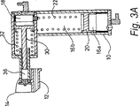
図3Aおよび図3Bにおいて、本発明による装置のさらなる実施例が概略的に示される。図3Bの断面の平面は、図3Aの断面の平面に対して90°である。
Example 2
In FIG. 3A and FIG. 3B, a further embodiment of the device according to the invention is schematically shown. The plane of the cross section of FIG. 3B is 90 ° with respect to the plane of the cross section of FIG. 3A.
図3A、図3Bに示される実施例は、図1および図2に示されたものに実質的に類似し、同じ構成要素は共通の参照番号で表わされる。2つの実施例の主要な差異は、図3A、図3Bに示される例においてはプライミングチャンバ16の長軸が主要燃焼チャンバ18の長軸に直交するよう90°回転していることである。
The embodiment shown in FIGS. 3A and 3B is substantially similar to that shown in FIGS. 1 and 2 and the same components are represented by common reference numerals. The main difference between the two embodiments is that in the example shown in FIGS. 3A and 3B, the major axis of the priming chamber 16 is rotated 90 ° so that it is perpendicular to the major axis of the
より小型の全体形状を提供することとともに、以下を含む他の潜在的な利益がある:
主要燃焼チャンバ18の点火プラグ(または他の点火手段)は端面に装着されることができ、燃焼チャンバ18内でより中央に位置をとり、そのためはるかに一定な点火および燃焼プロファイルを与えることとなる;
プライミングチャンバから主要チャンバへの空気入口はより接線方向であって放射線状でない位置をとることができ、そのため点火前の主要チャンバにおける燃料/空気混合体の混合を向上させることとなる;
主要チャンバおよびプライミングチャンバが直径の異なるボアを有するように装置を製造するほうが、例1で説明された配列よりも容易である。
Along with providing a smaller overall shape, there are other potential benefits including:
The spark plug (or other ignition means) of the
The air inlet from the priming chamber to the main chamber can be in a more tangential and non-radial position, thus improving the mixing of the fuel / air mixture in the main chamber before ignition;
It is easier to manufacture the device so that the main chamber and the priming chamber have different diameter bores than the arrangement described in Example 1.
プライミングチャンバ16と主要チャンバ18との間の一方向のガスフロー連通は短いアパーチャ26によって与えられ、このアパーチャ内に一方通行の逆止バルブがある。
One-way gas flow communication between the priming chamber 16 and the
プライミング燃焼チャンバおよび主要燃焼チャンバのそれぞれの排出バルブ40、42の適切に時間決めされた動作によって、適切な通気などが達成される。プライミングピストン20が開始位置に戻ると、一方通行の逆止バルブ44を介して空気がプライミングチャンバ16に入る。
Appropriate ventilation and the like is achieved by appropriately timed operation of the respective exhaust valves 40, 42 of the priming combustion chamber and the main combustion chamber. When the
例3
これは本発明による装置の別の実施例に関し、図4の概略的な断面図に示される。ここで示される実施例も、必要不可欠な構成要素および一般的動作については例1および例2で説明されたものと同様である。この例において、プライミングチャンバ16は(例2に対して)さらに90°回転され、プライミング燃焼チャンバおよび主要燃焼チャンバの長軸は平行であるがオフセットであって、プライミングチャンバは主要チャンバの下側に装着され、反対方向に配向される。ここでも、同じ構成要素は共通の参照番号で表わされる
。
Example 3
This relates to another embodiment of the device according to the invention and is shown in the schematic cross-sectional view of FIG. The embodiments shown here are also similar to those described in Examples 1 and 2 with respect to essential components and general operation. In this example, the priming chamber 16 is rotated an additional 90 ° (relative to Example 2), and the major axis of the priming combustion chamber and the main combustion chamber are parallel but offset so that the priming chamber is below the main chamber. Mounted and oriented in opposite direction. Again, the same components are represented by common reference numbers.
動作のシーケンスは実質的に例1および例2に説明された通りであり、プライミングピストン20の動きが導管26を通して空気を主要燃焼チャンバ18に強制し、導管は、必要とされる加圧された燃料/空気混合体を与えるために一方通行の逆止バルブを組込む。
The sequence of operation is substantially as described in Examples 1 and 2, with the movement of the
このシーケンスの次の部分の変形例は、主要燃焼チャンバにおける燃焼が遅延し、プライミング燃焼チャンバの排出バルブ40が開かれることである。図4に示されるように、これは、たとえば燃焼チャンバなどからとられたパイロット圧パルス信号を含む機械的入力、または時間決めされた電気的信号のいずれかによって、有効になり得る。この排出バルブが開いた状態で、プライミングピストン20は戻りばねによって駆動されてホーム位置に戻り、この時点で主要燃焼チャンバ18において点火が起こる。この遅延の利益は、通常は装置から排出される作動ピストンの前に押込まれた空気が、ここではプライミング燃焼チャンバ16(そこでは排出バルブも開いている)を通り、一方通行の逆止バルブ50を介して出て行くことができることであり、燃焼生成物の大部分を押出し、次の動作のためにプライミングチャンバ内に大部分のきれいな空気を残す。
A variation of the next part of the sequence is that combustion in the main combustion chamber is delayed and the priming combustion chamber exhaust valve 40 is opened. As shown in FIG. 4, this can be effected by either a mechanical input including a pilot pressure pulse signal taken from, for example, a combustion chamber, or a timed electrical signal. With this exhaust valve open, the
このアプローチは、例1および例2に説明された実施例においてもたとえば接続管などを用いることによって容易に組込まれることができ、接続チューブは作動ピストンの前部からプライミングチャンバまで、そしてその中にまで空気が入れるように流路を与え、排出のシーケンスおよびピストン運動が上述のように変形される。 This approach can also be easily incorporated in the embodiments described in Examples 1 and 2, for example by using a connecting tube, etc., where the connecting tube extends from the front of the working piston to the priming chamber and into it. A flow path is provided for air to enter, and the discharge sequence and piston motion are modified as described above.
示される代替的な構成は排出バルブの機械的動作にさらに追加的な範囲を与える。なぜなら、バルブがノズルおよびノズルガード(図4には示されない)に近接し、必要であれば、その動きがさらに容易にバルブの動作にリンクされ得るからである。 The alternative configuration shown provides additional range for the mechanical operation of the discharge valve. This is because the valve is in close proximity to the nozzle and nozzle guard (not shown in FIG. 4) and, if necessary, its movement can be more easily linked to the operation of the valve.
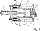
例5
これは本発明による装置のさらに別の実施例に関する。ここでも、必要不可欠な構成要素および動作の一般的原理は前述の例に説明された通りである。さらなる実施例の概略的断面図は図5に示される。ここでも、同じ構成要素は共通の参照番号で表わされる。
Example 5
This relates to a further embodiment of the device according to the invention. Again, the essential components and general principles of operation are as described in the previous examples. A schematic cross-sectional view of a further embodiment is shown in FIG. Again, the same components are represented by common reference numbers.
この実施例において、プライミング燃焼チャンバ16は一般に環状であり、実質的に主要燃焼チャンバ18を囲む。プライミングチャンバ16からの空気は一方通行の逆止バルブに関連付けられる導管を通じて主要チャンバ18に強制され、主要チャンバの加圧された燃料/空気混合体をもたらす。バルブおよび排出の選択例は前述の例に説明された通りであり得る。
In this embodiment, the priming combustion chamber 16 is generally annular and substantially surrounds the
Claims (13)
ム」位置か、またはその近くにあるときに起る、請求項6または7に記載の装置。8. Apparatus according to claim 6 or 7, wherein the discharge of combustion products from the priming combustion chamber occurs when the priming piston is at or near the "home" position.
Applications Claiming Priority (2)
| Application Number | Priority Date | Filing Date | Title |
|---|---|---|---|
| GB0309305 | 2003-04-24 | ||
| PCT/GB2004/001716 WO2004093948A1 (en) | 2003-04-24 | 2004-04-22 | Portable combustion-powered device with priming combustion chamber and main combustion chamber |
Publications (3)
| Publication Number | Publication Date |
|---|---|
| JP2006524079A JP2006524079A (en) | 2006-10-26 |
| JP2006524079A5 JP2006524079A5 (en) | 2007-06-07 |
| JP4597964B2 true JP4597964B2 (en) | 2010-12-15 |
Family
ID=33306516
Family Applications (1)
| Application Number | Title | Priority Date | Filing Date |
|---|---|---|---|
| JP2006506157A Expired - Fee Related JP4597964B2 (en) | 2003-04-24 | 2004-04-22 | Combustion-driven portable device having a priming combustion chamber and a main combustion chamber |
Country Status (6)
| Country | Link |
|---|---|
| US (1) | US7281502B2 (en) |
| EP (1) | EP1615684B1 (en) |
| JP (1) | JP4597964B2 (en) |
| AT (1) | ATE439882T1 (en) |
| DE (1) | DE602004022647D1 (en) |
| WO (1) | WO2004093948A1 (en) |
Families Citing this family (13)
| Publication number | Priority date | Publication date | Assignee | Title |
|---|---|---|---|---|
| EP1434612A1 (en) * | 2001-10-13 | 2004-07-07 | Team Holdings (UK) Limited | Self-priming portable device |
| US11590286B2 (en) | 2004-11-22 | 2023-02-28 | Kaleo, Inc. | Devices, systems and methods for medicament delivery |
| WO2006083876A2 (en) * | 2005-02-01 | 2006-08-10 | Intelliject, Llc | Devices, systems, and methods for medicament delivery |
| TWI341773B (en) | 2005-11-16 | 2011-05-11 | Illinois Tool Works | Fuel supply and combustion chamber systems for fastener-driving tools |
| US8347832B2 (en) * | 2008-10-31 | 2013-01-08 | Illinois Tool Works Inc. | Fuel supply and combustion chamber systems for fastener-driving tools |
| US9173999B2 (en) | 2011-01-26 | 2015-11-03 | Kaleo, Inc. | Devices and methods for delivering medicaments from a multi-chamber container |
| JP5435434B2 (en) * | 2011-06-03 | 2014-03-05 | Smc株式会社 | Piston assembly, fluid pressure cylinder, and method of manufacturing piston assembly |
| JP6297794B2 (en) | 2013-06-12 | 2018-03-20 | 株式会社ダイセル | Syringe |
| WO2017004345A1 (en) | 2015-06-30 | 2017-01-05 | Kaleo, Inc. | Auto-injectors for administration of a medicament within a prefilled syringe |
| WO2019156239A1 (en) * | 2018-02-09 | 2019-08-15 | 株式会社ダイセル | Injector and method of injecting solution containing live cells into injection-target cell nuclei using said injector |
| WO2019156237A1 (en) * | 2018-02-09 | 2019-08-15 | 株式会社ダイセル | Injector |
| DE202018102738U1 (en) * | 2018-05-16 | 2018-09-10 | Ira Yasmin Lehmann | Needle-free injection system |
| WO2021030210A1 (en) | 2019-08-09 | 2021-02-18 | Kaleo, Inc. | Devices and methods for delivery of substances within a prefilled syringe |
Family Cites Families (6)
| Publication number | Priority date | Publication date | Assignee | Title |
|---|---|---|---|---|
| US3802430A (en) * | 1972-06-30 | 1974-04-09 | L Arnold | Disposable pyrotechnically powered injector |
| US4712379A (en) * | 1987-01-08 | 1987-12-15 | Pow-R Tools Corporation | Manual recycler for detonating impact tool |
| FR2800619B1 (en) * | 1999-11-05 | 2002-02-08 | Cross Site Technologies | NEEDLELESS SYRINGE WITH TEMPORARILY RETAINED PUSHING MEDIA |
| GB0012165D0 (en) * | 2000-05-20 | 2000-07-12 | Team Consulting Ltd | Portable device with consistent power output |
| EP1434612A1 (en) * | 2001-10-13 | 2004-07-07 | Team Holdings (UK) Limited | Self-priming portable device |
| US6874452B2 (en) * | 2002-01-15 | 2005-04-05 | Joseph S. Adams | Resonant combustion chamber and recycler for linear motors |
-
2004
- 2004-04-22 DE DE602004022647T patent/DE602004022647D1/en not_active Expired - Lifetime
- 2004-04-22 WO PCT/GB2004/001716 patent/WO2004093948A1/en active Application Filing
- 2004-04-22 JP JP2006506157A patent/JP4597964B2/en not_active Expired - Fee Related
- 2004-04-22 AT AT04728846T patent/ATE439882T1/en not_active IP Right Cessation
- 2004-04-22 US US10/554,438 patent/US7281502B2/en not_active Expired - Fee Related
- 2004-04-22 EP EP04728846A patent/EP1615684B1/en not_active Expired - Lifetime
Also Published As
| Publication number | Publication date |
|---|---|
| US7281502B2 (en) | 2007-10-16 |
| EP1615684A1 (en) | 2006-01-18 |
| US20070079777A1 (en) | 2007-04-12 |
| DE602004022647D1 (en) | 2009-10-01 |
| WO2004093948A1 (en) | 2004-11-04 |
| JP2006524079A (en) | 2006-10-26 |
| ATE439882T1 (en) | 2009-09-15 |
| EP1615684B1 (en) | 2009-08-19 |
Similar Documents
| Publication | Publication Date | Title |
|---|---|---|
| US7351220B2 (en) | Portable device for delivering medicaments and the like | |
| JP4597964B2 (en) | Combustion-driven portable device having a priming combustion chamber and a main combustion chamber | |
| US11878147B2 (en) | Needle-less injector and method of fluid delivery | |
| US7699802B2 (en) | Needle-less injector | |
| US20040035491A1 (en) | Method and apparatus for needle-less injection with a degassed fluid | |
| EP0776224B1 (en) | Needleless syringe for particle delivery | |
| RU2129445C1 (en) | Needless syringe | |
| US7814871B2 (en) | Self-priming portable device | |
| US20050192530A1 (en) | Method and apparatus for needle-less injection with a degassed fluid | |
| GB1594505A (en) | Multi-dose jet injection device powered by foot operated pump | |
| CA2197711C (en) | Particle delivery | |
| GB2407290A (en) | Apparatus for firing a product |
Legal Events
| Date | Code | Title | Description |
|---|---|---|---|
| A521 | Request for written amendment filed |
Free format text: JAPANESE INTERMEDIATE CODE: A523 Effective date: 20070416 |
|
| A621 | Written request for application examination |
Free format text: JAPANESE INTERMEDIATE CODE: A621 Effective date: 20070416 |
|
| A131 | Notification of reasons for refusal |
Free format text: JAPANESE INTERMEDIATE CODE: A131 Effective date: 20091201 |
|
| A521 | Request for written amendment filed |
Free format text: JAPANESE INTERMEDIATE CODE: A523 Effective date: 20100226 |
|
| TRDD | Decision of grant or rejection written | ||
| A01 | Written decision to grant a patent or to grant a registration (utility model) |
Free format text: JAPANESE INTERMEDIATE CODE: A01 Effective date: 20100831 |
|
| A01 | Written decision to grant a patent or to grant a registration (utility model) |
Free format text: JAPANESE INTERMEDIATE CODE: A01 |
|
| A61 | First payment of annual fees (during grant procedure) |
Free format text: JAPANESE INTERMEDIATE CODE: A61 Effective date: 20100922 |
|
| R150 | Certificate of patent or registration of utility model |
Free format text: JAPANESE INTERMEDIATE CODE: R150 |
|
| FPAY | Renewal fee payment (event date is renewal date of database) |
Free format text: PAYMENT UNTIL: 20131001 Year of fee payment: 3 |
|
| LAPS | Cancellation because of no payment of annual fees |