JP4597861B2 - Signal switching device, signal distribution device, display device, and signal transmission system - Google Patents
Signal switching device, signal distribution device, display device, and signal transmission system Download PDFInfo
- Publication number
- JP4597861B2 JP4597861B2 JP2005511604A JP2005511604A JP4597861B2 JP 4597861 B2 JP4597861 B2 JP 4597861B2 JP 2005511604 A JP2005511604 A JP 2005511604A JP 2005511604 A JP2005511604 A JP 2005511604A JP 4597861 B2 JP4597861 B2 JP 4597861B2
- Authority
- JP
- Japan
- Prior art keywords
- reading
- physical address
- output destination
- input source
- video signal
- Prior art date
- Legal status (The legal status is an assumption and is not a legal conclusion. Google has not performed a legal analysis and makes no representation as to the accuracy of the status listed.)
- Active
Links
Images


Classifications
-
- H—ELECTRICITY
- H04—ELECTRIC COMMUNICATION TECHNIQUE
- H04N—PICTORIAL COMMUNICATION, e.g. TELEVISION
- H04N5/00—Details of television systems
- H04N5/76—Television signal recording
- H04N5/765—Interface circuits between an apparatus for recording and another apparatus
- H04N5/775—Interface circuits between an apparatus for recording and another apparatus between a recording apparatus and a television receiver
-
- H—ELECTRICITY
- H04—ELECTRIC COMMUNICATION TECHNIQUE
- H04N—PICTORIAL COMMUNICATION, e.g. TELEVISION
- H04N5/00—Details of television systems
- H04N5/44—Receiver circuitry for the reception of television signals according to analogue transmission standards
-
- H—ELECTRICITY
- H04—ELECTRIC COMMUNICATION TECHNIQUE
- H04N—PICTORIAL COMMUNICATION, e.g. TELEVISION
- H04N21/00—Selective content distribution, e.g. interactive television or video on demand [VOD]
- H04N21/40—Client devices specifically adapted for the reception of or interaction with content, e.g. set-top-box [STB]; Operations thereof
- H04N21/41—Structure of client; Structure of client peripherals
- H04N21/4104—Peripherals receiving signals from specially adapted client devices
- H04N21/4108—Peripherals receiving signals from specially adapted client devices characterised by an identification number or address, e.g. local network address
-
- H—ELECTRICITY
- H04—ELECTRIC COMMUNICATION TECHNIQUE
- H04N—PICTORIAL COMMUNICATION, e.g. TELEVISION
- H04N21/00—Selective content distribution, e.g. interactive television or video on demand [VOD]
- H04N21/40—Client devices specifically adapted for the reception of or interaction with content, e.g. set-top-box [STB]; Operations thereof
- H04N21/41—Structure of client; Structure of client peripherals
- H04N21/4104—Peripherals receiving signals from specially adapted client devices
- H04N21/4122—Peripherals receiving signals from specially adapted client devices additional display device, e.g. video projector
-
- H—ELECTRICITY
- H04—ELECTRIC COMMUNICATION TECHNIQUE
- H04N—PICTORIAL COMMUNICATION, e.g. TELEVISION
- H04N21/00—Selective content distribution, e.g. interactive television or video on demand [VOD]
- H04N21/40—Client devices specifically adapted for the reception of or interaction with content, e.g. set-top-box [STB]; Operations thereof
- H04N21/41—Structure of client; Structure of client peripherals
- H04N21/426—Internal components of the client ; Characteristics thereof
-
- H—ELECTRICITY
- H04—ELECTRIC COMMUNICATION TECHNIQUE
- H04N—PICTORIAL COMMUNICATION, e.g. TELEVISION
- H04N21/00—Selective content distribution, e.g. interactive television or video on demand [VOD]
- H04N21/40—Client devices specifically adapted for the reception of or interaction with content, e.g. set-top-box [STB]; Operations thereof
- H04N21/43—Processing of content or additional data, e.g. demultiplexing additional data from a digital video stream; Elementary client operations, e.g. monitoring of home network or synchronising decoder's clock; Client middleware
- H04N21/436—Interfacing a local distribution network, e.g. communicating with another STB or one or more peripheral devices inside the home
- H04N21/4363—Adapting the video or multiplex stream to a specific local network, e.g. a IEEE 1394 or Bluetooth® network
- H04N21/43632—Adapting the video or multiplex stream to a specific local network, e.g. a IEEE 1394 or Bluetooth® network involving a wired protocol, e.g. IEEE 1394
-
- H—ELECTRICITY
- H04—ELECTRIC COMMUNICATION TECHNIQUE
- H04N—PICTORIAL COMMUNICATION, e.g. TELEVISION
- H04N5/00—Details of television systems
- H04N5/222—Studio circuitry; Studio devices; Studio equipment
- H04N5/262—Studio circuits, e.g. for mixing, switching-over, change of character of image, other special effects ; Cameras specially adapted for the electronic generation of special effects
- H04N5/268—Signal distribution or switching
-
- H—ELECTRICITY
- H04—ELECTRIC COMMUNICATION TECHNIQUE
- H04N—PICTORIAL COMMUNICATION, e.g. TELEVISION
- H04N5/00—Details of television systems
- H04N5/76—Television signal recording
- H04N5/84—Television signal recording using optical recording
- H04N5/85—Television signal recording using optical recording on discs or drums
Description
本発明は、複数の入力信号を切り替える信号切替装置と、入力信号を複数の機器へ出力する信号分配装置と、映像を表示する表示装置と、信号伝送システムとに関する。 The present invention relates to a signal switching device that switches a plurality of input signals, a signal distribution device that outputs input signals to a plurality of devices, a display device that displays video, and a signal transmission system.
近年、デジタルビデオや、通信衛星放送におけるデジタル技術の普及に鑑みて、こうしたデジタル技術を用いたデジタル機器を、同一のネットワーク上に接続して制御するシステムが構成されつつある。 In recent years, in view of the spread of digital technology in digital video and communication satellite broadcasting, a system for connecting and controlling digital devices using such digital technology on the same network is being constructed.
デジタルインターフェースの一つとして、DVI(Digital Visual Interface)と呼ばれるものがある。このインターフェースは、デジタル映像信号を圧縮無しで伝送することができる高速な信号伝送路と、受信側の機器が表示することができる信号のフォーマット等の情報を上流(信号源側)に提供するために保持するEDID(Extended Display Identification Data)メモリと、前記情報を読み出すためのDDC(DISPLAY DATA CHANNEL)とを有する(例えば、“Digital Visual Interface DVI ,revision 1.0”、2.2 Plug and Play specification、[online]、1999年4月2日,Digital Display Working Group、[2002年8月29日検索]、インターネットURL:http://www.ddwg.org/downloads.html参照)。さらに、DVIは、EDIDメモリに記録されている情報が読める状態にあることや、その内容が変化したことを知らせるHPD(Hot Plug Detect)線を備える。HPD線は、それが設けられている機器に上流の機器から電源が供給されたときのみ、上記の内容が変化したことを示す情報を出力できる。 One of digital interfaces is called DVI (Digital Visual Interface). This interface provides high-speed signal transmission paths that can transmit digital video signals without compression, and information such as signal formats that can be displayed by the receiving-side equipment to the upstream (signal source side). EDID (Extended Display Identification Data) memory and DDC (DISPLAY DATA CHANNEL) for reading the information (for example, “Digital Visual Interface DVI, revision 1.0”, 2.2 Plug and Play specification, [online] , April 2, 1999, Digital Display Working Group, [Search August 29, 2002], Internet URL: http://www.ddwg.org/downloads.html). Furthermore, the DVI includes an HPD (Hot Plug Detect) line that informs that the information recorded in the EDID memory is readable and the content has changed. The HPD line can output information indicating that the above contents have changed only when power is supplied from an upstream device to the device provided with the HPD line.
このインターフェース(DVI)に対し、接続されている機器を制御するためのコントロール線を加えることを検討する。例として、欧州で使用されているSCARTコネクタ(CENELEC,EN 50049−1:1997/A1:1998)で用いられるコントロール線を追加することを検討する。 Consider adding a control line for controlling the connected equipment to this interface (DVI). As an example, consider adding control lines used in SCART connectors used in Europe (CENELEC, EN 50049-1: 1997 / A1: 1998).
コントロール線はDVIを持つ全ての機器の入力と出力の間で接続されバスを構成する。コントロール線では、DVIによって構築されたネットワーク上でそれぞれの機器を特定するための情報である論理アドレスが規定される。論理アドレスは、それぞれの機器の種類(DVD録画再生装置、STB(Set Top Box)、TVなど)と、同種の機器相互間での調停とにより、「STBb」などと決定され、それぞれのコントロール線が追加されたDVIを備えた機器中で保持される。 The control line is connected between the input and output of all devices having DVI to form a bus. In the control line, a logical address, which is information for specifying each device on the network constructed by DVI, is defined. The logical address is determined to be “STBb” or the like based on the type of each device (DVD recording / playback apparatus, STB (Set Top Box), TV, etc.) and arbitration between the same type of devices. Is held in the device with the added DVI.
コントロール線を通じて送られるメッセージのヘッダには、メッセージの送信元の論理アドレスと、メッセージの宛先の論理アドレスとが含まれる。メッセージには、例えば全てのコントロール線が追加されたDVIを備えた機器を宛先とするブロードキャストメッセージも含まれる。それぞれのコントロール線が追加されたDVIを備えた機器は、自身の論理アドレスとヘッダ中の宛先とを比較することによって、ブロードキャストメッセージが自身が対応すべきメッセージであるか否かを判定する。 The header of the message sent through the control line includes the logical address of the message source and the logical address of the message destination. The message includes, for example, a broadcast message addressed to a device having a DVI to which all control lines are added. A device having a DVI to which each control line has been added determines whether or not the broadcast message is a message that the broadcast message should correspond to by comparing its own logical address with the destination in the header.
上述したように、DVIにコントロール線を加えることにより、TV等の表示機器と、DVD録画再生装置などの録画・再生機器とを一本のケーブルだけで接続するインターフェースを実現することができる。 As described above, by adding a control line to the DVI, it is possible to realize an interface that connects a display device such as a TV and a recording / playback device such as a DVD recording / playback apparatus with a single cable.
しかしながら、DVIと前記コントロール線とを組み合わせただけでは、ある機器が他の機器を制御することはできない。特にスイッチやデュプリケータといった信号切替・分配装置を含んだシステムにおいては、そのシステムを構成するある機器が他の機器を制御することができることをユーザは所望するが、それは実現されていない。例えば、各機器が電源ON/OFF、EDIDメモリに記録されている情報が読める状態/読めない状態などの各状態において、機器コントロールが可能な状態か否かということは規定されていない。 However, a device cannot control another device only by combining DVI and the control line. In particular, in a system including a signal switching / distribution device such as a switch or a duplicator, a user desires that a certain device constituting the system can control another device, but this is not realized. For example, it is not stipulated whether or not each device can be controlled in each state such as power ON / OFF and a state where information recorded in the EDID memory is readable / unreadable.
また、機器コントロールにおいてルート機器は1つとなるように規定されており、「TV」に相当する論理アドレスも1つのみ定められている。しかしながら、ある機器に誤ってあるいは意図的に2台以上のTV(=ルート機器)が接続された場合の上記ある機器の動作や、上記ある機器が誤動作することを防ぐための方法などは規定されていない。 In the device control, the number of root devices is defined as one, and only one logical address corresponding to “TV” is defined. However, the operation of a certain device when two or more TVs (= root devices) are accidentally or intentionally connected to a certain device, a method for preventing the certain device from malfunctioning, etc. are stipulated. Not.
このように、DVIとコントロール線とを組み合わせただけでは、ある機器は、自らに接続されている他の機器を制御することはできない。 In this way, a certain device cannot control other devices connected to itself only by combining the DVI and the control line.
本発明は、かかる課題に鑑みてなされたものであり、映像信号通信部、DDC、およびHPDを有するインターフェースを備えるとともに、接続された機器を制御する、または接続された機器に制御される信号切替装置、信号分配装置、および表示装置を提供することを目的とする。 The present invention has been made in view of such a problem, and includes an interface having a video signal communication unit, a DDC, and an HPD, and controls a connected device or a signal switching controlled by the connected device. An object is to provide a device, a signal distribution device, and a display device.
上述した課題を解決するとともに上述した目的を達成するために、本発明の信号切替装置は、複数の映像信号入力のいずれかを選択する選択手段と、情報を保持するためのメモリと、映像信号の出力先である出力先機器から情報を読み取るための読み取りチャネルと、本体の物理アドレス及び前記出力先機器の状態を示す情報を前記読み取りチャネルを介して読み取る読み取り手段と、前記読み取り手段によって読み取られた情報を前記メモリに格納する格納手段と、前記メモリに格納された情報を読み出す読み出し手段と、複数の映像信号入力の入力元である複数の入力元機器へ情報を出力するための複数の読み出しチャネルと、前記出力先機器の状態を示す情報を前記読み出しチャネルを介して出力する出力手段とを備える。 In order to solve the above-described problems and achieve the above-described object, a signal switching device according to the present invention includes a selection unit that selects any one of a plurality of video signal inputs, a memory that holds information, and a video signal. A reading channel for reading information from an output destination device which is an output destination of the device, a reading means for reading information indicating a physical address of a main body and a state of the output destination device via the reading channel, and the reading means Storage means for storing the stored information in the memory, reading means for reading the information stored in the memory, and a plurality of readouts for outputting information to a plurality of input source devices that are input sources of a plurality of video signal inputs A channel and output means for outputting information indicating the state of the output destination device via the read channel.
本発明の信号分配装置は、複数の映像信号の出力先である複数の出力先機器の一部又は全部に映像信号を出力するための分配手段と、情報を保持するためのメモリと、複数の前記出力先機器から情報を読み取るための複数の読み取りチャネルと、本体の物理アドレス及び前記出力先機器の状態を示す情報を前記読み取りチャネルを介して読み取る読み取り手段と、前記読み取り手段によって読み取られた情報を前記メモリに格納する格納手段と、前記メモリに格納された情報を読み出す読み出し手段と、映像信号の入力元である入力元機器へ情報を出力するための読み出しチャネルと、前記出力先機器の状態を示す情報を前記読み出しチャネルを介して出力する出力手段とを備える。 The signal distribution device of the present invention includes a distribution means for outputting a video signal to some or all of a plurality of output destination devices that are output destinations of a plurality of video signals, a memory for holding information, a plurality of A plurality of reading channels for reading information from the output destination device, reading means for reading information indicating a physical address of the main body and the state of the output destination device via the reading channel, and information read by the reading means Storage means for storing information in the memory, reading means for reading information stored in the memory, a read channel for outputting information to an input source device that is an input source of a video signal, and a state of the output destination device Output means for outputting information indicating the above via the read channel.
本発明の表示装置は、複数の映像のいずれかを選択する選択手段と、前記選択手段によって選択された映像を表示する表示手段と、映像信号の入力元である入力元機器の物理アドレス及び本体の状態を示す情報を保持するためのメモリと、前記メモリに保持された情報を読み出す読み出し手段と、前記入力元機器へ情報を出力するための読み出しチャネルと、前記本体の状態を示す情報を前記読み出しチャネルを介して出力する出力手段とを備える。 The display device of the present invention includes a selection unit that selects one of a plurality of videos, a display unit that displays a video selected by the selection unit, and a physical address and a main body of an input source device that is an input source of the video signal A memory for holding information indicating the status of the data, a reading means for reading the information held in the memory, a read channel for outputting information to the input source device, and information indicating the status of the main body Output means for outputting via a read channel.
このように、本発明の信号切替装置、信号分配装置、および表示装置は、メモリと、読み出しチャネルとを備え、そのメモリに、本体の物理アドレスと、接続される機器の状態を示す情報、または本体の状態を示す情報とが格納されるので、接続された機器を制御する、または接続された機器に制御される、ということが可能である。 As described above, the signal switching device, the signal distribution device, and the display device of the present invention include a memory and a read channel, and in the memory, information indicating the physical address of the main body and the state of the connected device, or Since information indicating the state of the main body is stored, it is possible to control the connected device or to be controlled by the connected device.
また、本発明の信号伝送システムは、映像信号送信装置と、映像信号処理装置と、映像信号受信装置とを備え、前記映像信号処理装置は、情報を保持するためのメモリと、前記映像信号受信装置から情報を読み取るための読み取りチャネルと、前記映像信号処理装置の物理アドレス及び前記映像信号受信装置の状態を示す情報を前記読み取りチャネルを介して読み取る読み取り手段と、前記読み取り手段によって読み取られた情報を前記メモリに格納する格納手段と、前記メモリに格納された情報を読み出す読み出し手段と、前記映像信号送信装置へ情報を出力するための読み出しチャネルと、前記映像信号受信装置の状態を示す情報を前記読み出しチャネルを介して出力する出力手段とを有する。 The signal transmission system of the present invention includes a video signal transmitting device, a video signal processing device, and a video signal receiving device, wherein the video signal processing device includes a memory for holding information and the video signal receiving device. A reading channel for reading information from a device, a reading means for reading information indicating a physical address of the video signal processing device and a state of the video signal receiving device via the reading channel, and information read by the reading device Storing means in the memory, reading means for reading the information stored in the memory, a read channel for outputting information to the video signal transmitting apparatus, and information indicating the state of the video signal receiving apparatus Output means for outputting via the readout channel.
このように、本発明の信号伝送システムの映像信号処理装置は、メモリと、読み出しチャネルとを備え、そのメモリに、映像信号処理装置の物理アドレスと、映像信号受信装置の状態を示す情報とが格納されるので、本発明の信号伝送システムでは、映像信号送信装置、映像信号処理装置、および映像信号受信装置は、相互に制御する、または制御される、ということが可能である。 As described above, the video signal processing apparatus of the signal transmission system of the present invention includes the memory and the read channel, and the memory includes the physical address of the video signal processing apparatus and information indicating the state of the video signal receiving apparatus. Therefore, in the signal transmission system of the present invention, the video signal transmitting device, the video signal processing device, and the video signal receiving device can be controlled or controlled with respect to each other.
つまり、本発明によれば、DVIに制御線を加えて、非圧縮の映像信号伝送に加えて接続された機器の制御が可能となる。 That is, according to the present invention, it is possible to control connected devices in addition to non-compressed video signal transmission by adding a control line to DVI.
また、DVIを用いたスイッチやデュプリケータなどが実現できる。 Also, a switch or duplicator using DVI can be realized.
さらにTVがスイッチやデュプリケータなどを介して2台以上繋がっていても、スイッチやデュプリケータが切り分けた範囲内で接続された機器の制御を行うことができるという効果がある。 Furthermore, even when two or more TVs are connected via a switch, a duplicator, or the like, there is an effect that the connected devices can be controlled within a range where the switch or the duplicator is separated.
更に、本発明は、本発明の信号切替装置または信号分配装置の特徴的な構成手段をステップとする方法として実現したり、それらのステップを含むプログラムとして実現することもできる。そのプログラムは、CD−ROM等の記録媒体や通信ネットワーク等の伝送媒体を介して流通させることもできる。 Furthermore, the present invention can be realized as a method using characteristic constituent means of the signal switching device or the signal distribution device of the present invention as a step, or as a program including these steps. The program can be distributed via a recording medium such as a CD-ROM or a transmission medium such as a communication network.
以下、本発明を実施するための最良の形態を、図面を参照して説明する。 The best mode for carrying out the present invention will be described below with reference to the drawings.
(実施の形態1)
先ず、実施の形態1の信号伝送システムの構成を、図1〜図3を用いて説明する。
(Embodiment 1)
First, the configuration of the signal transmission system according to the first embodiment will be described with reference to FIGS.
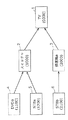
図1は実施の形態1の信号伝送システムの構成を示すブロック図である。図1に示すように、実施の形態1の信号伝送システムは、TV1と、スイッチャ2と、録画機a3と、DVDa4と、STBa5と、STBb6とで構成されている。TV1にはスイッチャ2と録画機a3とが接続され、スイッチャ2にはDVDa4とSTBa5とが接続され、録画機a3にはSTBb6が接続されている。
FIG. 1 is a block diagram showing the configuration of the signal transmission system according to the first embodiment. As shown in FIG. 1, the signal transmission system of the first embodiment includes a
TV1は表示装置である。スイッチャ2は、DVDa4からの映像信号と、STBa5からの映像信号とのいずれかを選択する装置である。録画機a3はSTBb6からの映像信号を録画する装置である。DVDa4はDVDに記録されている映像信号を再生する装置である。STBa5及びSTBb6は、映像信号を受信して出力する装置である。
The TV 1 is a display device. The
図1では、TV1、スイッチャ2、録画機a3、DVDa4、STBa5、及びSTBb6を示す各ブロック内に数字が記載されている。数字は、その数字が含まれるブロックが示す装置の物理アドレスである。
In FIG. 1, numerals are written in the respective
物理アドレスは、互いに接続されている各装置がどのように接続されているか(実際はコントロール線の接続のされ方)を特定するための情報である。物理アドレスは、受信側の機器中に設置されたEDIDメモリの所定の位置に保持され、起動時にDDCを通じて読み出される。ここで、受信側の機器とは、TV1とスイッチャ2とについてはTV1を意味し、スイッチャ2とDVDa4とについてはスイッチャ2を意味する。コントロール線が追加されたDVIを備えた機器(例えば、スイッチャ2)は、自身の物理アドレスからそれぞれの子機器(入力側に直接繋がっている機器)の物理アドレスを生成し、自身の論理アドレスとともに保持する。
The physical address is information for specifying how the devices connected to each other are connected (actually how the control lines are connected). The physical address is held at a predetermined position in the EDID memory installed in the receiving device, and is read through the DDC at the time of activation. Here, the receiving device means TV1 for TV1 and
TVなどの表示機器は、信号の最終到着点の機器(ルート機器)であるため、下流の機器から自らの物理アドレスを読み出すことはできない。このため、ルート機器は電源投入時に例えば(0000)という物理アドレスを自ら設定し保持する。ルート機器に直接2台の機器が接続されている場合、それぞれの機器の物理アドレスは(1000)、(2000)と決定される。同様に、物理アドレスが(1000)である機器に3台の機器が接続されている場合、それぞれの機器の物理アドレスは(1100)、(1200)、(1300)と順次決定される。 Since a display device such as a TV is a device (route device) at the final arrival point of a signal, its own physical address cannot be read from a downstream device. For this reason, the root device sets and holds a physical address of (0000) for example when the power is turned on. When two devices are directly connected to the root device, the physical addresses of the devices are determined as (1000) and (2000). Similarly, when three devices are connected to a device whose physical address is (1000), the physical addresses of the respective devices are sequentially determined as (1100), (1200), and (1300).
図1は、ルート機器であるTV1の物理アドレスが(0000)であり、TV1に直接接続されているスイッチャ2および録画機a3の物理アドレスがそれぞれ(1000)、(2000)である状況を示している。また、図1は、物理アドレスが(1000)であるスイッチャ2に直接接続されているDVDa4およびSTBa5の物理アドレスがそれぞれ(1100)、(1200)である状況を示している。
FIG. 1 shows a situation where the physical address of the root device TV1 is (0000) and the physical addresses of the
図2は2入力1出力のスイッチャ2の構成を示す図である。
FIG. 2 is a diagram showing the configuration of the
図2に示すように、スイッチャ2は、第1の映像入力側のDVI(以下、「第1入力DVI」という。)を構成する映像入力部20aと、コントロール線(CTL)21aと、DDC22aと、HPD23aとを備えている。また、スイッチャ2は、第2の映像入力側のDVI(以下、「第2入力DVI」という。)を構成する映像入力部20bと、コントロール線(CTL)21bと、DDC22bと、HPD23bとを備えている。また、スイッチャ2は、映像出力側のDVIを構成する映像出力部24cと、コントロール線(CTL)25cと、DDC26cと、HPD27cとを備えている。
As shown in FIG. 2, the
更に、スイッチャ2は、スイッチ(SW)30と、EDIDメモリ32と、マイコン33とを備えている。
Further, the
スイッチ30は、映像入力部20aと、映像入力部20bとのいずれかを選択する。EDIDメモリ32は、TV1の状態を示す情報等を保持するためのメモリである。TV1の状態を示す情報は、例えば、TV1が受信することができる映像信号のフォーマットを示す情報である。また、TV1の状態を示す情報として、製品に関する情報(型番、シリアル番号、製造社名、製造年月日)や、映像フォーマットに関する情報(画素数、ガンマ、色情報(R,G,Bなど)や、タイミングに関する情報(サンプル数、フレームレート)もある。さらに、EDIDメモリ32には、少なくともスイッチ30によって選択された映像入力部(映像入力部20aまたは映像入力部20b)の物理アドレスが保持される。マイコン33は、EDIDメモリ32によって保持されている情報に基づいてスイッチャ2の状態を管理するとともに、スイッチ30及び、コントロール線21a,コントロール線21b,コントロール線25cを制御する。
The
ここで、DDC22a,DDC22bは読み出しチャネルの一例であり、DDC26cは読み取りチャネルの一例である。コントロール線21a,コントロール線21b,コントロール線25cは、制御信号伝送路の一例である。読み取り手段、格納手段、読み出し手段、出力手段、電圧検出手段、電源状態制御手段、電源供給手段、及びアドレス設定手段は、マイコン33に含まれている。
Here, the
図3は2入力のTV1の構成を示す図である。
FIG. 3 is a diagram showing the configuration of the 2-
図3に示すように、TV1は、スイッチャ2と同様に、第1入力DVIと、第2入力DVIとを備えている。すなわち、TV1は、映像入力部20a、コントロール線(CTL)21a、DDC22a、及びHPD23aと、映像入力部20b、コントロール線(CTL)21b、DDC22b、及びHPD23bとを備えている。また、TV1は、スイッチ(SW)41と、EDIDメモリ42と、マイコン43と、モニタ44とを備えている。図3において、図2に示す構成要素と同じ構成要素に関しては、同じ符号を付与し、説明を省略する。
As shown in FIG. 3, the
スイッチ41は、映像入力部20aと、映像入力部20bとのいずれかを選択する。EDIDメモリ42は、TV1の状態を示す情報等を保持するメモリである。さらに、EDIDメモリ42は、少なくともスイッチ41によって選択された映像入力部(映像入力部20aまたは映像入力部20b)の物理アドレスを保持する。マイコン43は、EDIDメモリ42によって保持されている情報に基づいてTV1の状態を管理するとともに、スイッチ41を制御する。モニタ44は、スイッチ41によって選択された映像入力部(映像入力部20aまたは映像入力部20b)からの映像信号に基づく映像を表示する。
The
次に、実施の形態1の信号伝送システムの動作を説明する。 Next, the operation of the signal transmission system according to the first embodiment will be described.
なお、以下の説明では、スイッチャ2の動作を説明するために、TV1、スイッチャ2、およびDVDa4の動作を、図4を用いて説明する。
In the following description, the operations of the
図4は、実施の形態1の信号伝送システムの動作の各手順を説明するシーケンス図である。 FIG. 4 is a sequence diagram illustrating each procedure of the operation of the signal transmission system according to the first embodiment.
まず、全ての機器が電源OFFである状態を想定する。つまり、TV1、スイッチャ2、録画機a3、DVDa4、STBa5、及びSTBb6の電源がOFFである状態を想定する。この状態で、ユーザがDVDa4の電源をONにし、PLAYボタンを押す場合を想定する。
First, assume a state in which all devices are powered off. That is, it is assumed that the
この場合、DVDa4は再生を始める(S1)。また、DVDa4はコントロール線に対してプルアップを行い、スイッチャ2に対して電源供給線(未記述)を通して+5ボルト電源を供給する(S2)。また、DVDa4は、スイッチャ2に対してEDIDメモリ32中に保持されているはずの自身の物理アドレスの入手を試みる(S3)。しかしながら、DVDa4以外の機器がまだ電源ONになっていないので、DVDa4は下流の機器(スイッチャ2)から自身の物理アドレスをまだ入手できない。そのため、DVDa4は、自身の物理アドレスを入手できるまでDDC22aを通して、自身の物理アドレスの読み取りのリトライを続ける。
In this case, the DVDa4 starts to play (S1). DVDa4 pulls up the control line and supplies +5 volt power to the
DVDa4はコントロール線21aを通して<Image View On>メッセージをTV1に送る(S4)。DVDa4は、そのメッセージの「送り元」のパラメータに自身の論理アドレスを、「宛先」のパラメータにTV1の論理アドレスを設定する。スイッチャ2のコントロール線21a、コントロール線21b、コントロール線25cは相互に接続されている。そのため、DVDa4からのメッセージはコントロール線に対してプルアップを行う機器が存在する限り、TV1まで届くことができる(S4)。
DVDa4 sends an <Image View On> message to TV1 through
TV1では、マイコン43が、コントロール線21aを介して<Image View On>メッセージを受け取ると、TV1の電源をONにし(S5)、映像を表示できる状態にする。
In the
スイッチャ2では、マイコン33が、コントロール線のプルアップを検出すると、スイッチャ2の電源をONにする(S6)。または、コントロール線上にメッセージが流れたことを受けて、マイコン33がスイッチャ2の電源をONにしてもよい(S6)。
In the
次に、スイッチャ2のマイコン33がTV1に対して+5ボルト電源を供給する(S7)。TV1では、マイコン43が、+5ボルト電源が供給されたことを検出すると、そのことを示す情報(電源供給に対する応答)をHPD23aを介して出力する(S8)。TV1のEDIDメモリ42には、TV1の物理アドレス(0000)と子機器の物理アドレス(1000)、(2000)とが設定されている。
Next, the
スイッチャ2では、マイコン33が、TV1に+5ボルト電源が供給されたことを示す情報(電源供給に対する応答)がTV1のHPD23aから出力されたことを検出すると、TV1からスイッチャ2の物理アドレス(1000)をDDC26c経由で読み出し、EDIDメモリ32に設定する(S9)。同時に、マイコン33は、TV1が受信することができる映像信号のフォーマットも読み出し、EDIDメモリ32に登録する(S9)。映像信号のフォーマットは、TV1が受信することができる映像信号の解像度および周波数を含む。なお、スイッチャ2がTV1からスイッチャ2の物理アドレスやTV1が受信することができる映像信号のフォーマットを読み出す際、TV1のマイコン43が、上記の物理アドレスやフォーマットをEDIDメモリ42から読み出し、DDC22a経由でスイッチャ2へ出力する。
In the
また、マイコン33は、スイッチャ2の子機器の物理アドレス(1100)と(1200)とをEDIDメモリ32に設定する(S10)。更に、マイコン33は、HPD23aからEDIDメモリ32に保持されている情報の内容が変化したことを示す情報を出力する(S11)。
Further, the
DVDa4は、スイッチャ2のEDIDメモリ32に保持されている情報の内容が変化したことを示す情報がHPD23aから出力されたことを検出すると、スイッチャ2からDVDa4の物理アドレス(1100)をDDC22a経由で読み出し、自らに設けられているメモリに設定する(S12)。同時に、DVDa4は、TV1が受信する映像信号のフォーマットもスイッチャ2から読み出し、自らに設けられているメモリに設定する(S12)。DVDa4は、メモリに設定したフォーマットを、出力する映像信号の設定に反映する。なお、DVDa4がスイッチャ2からDVDa4の物理アドレスやTV1が受信することができる映像信号のフォーマットを読み出す際、スイッチャ2のマイコン33が、上記の物理アドレスやフォーマットをEDIDメモリ32から読み出し、DDC22a経由でDVDa4へ出力する。
When the DVDa4 detects that information indicating that the content of the information held in the
DVDa4はコントロール線21aを通して<active source>メッセージをブロードキャストする(S13)。このメッセージにはDVDa4の物理アドレス(1100)が含まれる。TV1では、マイコン43が、コントロール線21aから<active source>メッセージを受け取ると、内部接続をDVDa4側に切り替える(S14)。すなわち、マイコン43が、スイッチ30が映像入力部20aを選択するように、スイッチ30を制御する(S14)。
DVDa4 broadcasts an <active source> message through
スイッチャ2では、マイコン33が、コントロール線21aから<active source>メッセージを受け取ると、メッセージ中の物理アドレス(1100)と、EDIDメモリ32に設定されているスイッチャ2の物理アドレス(1000)とを比較する。このとき、マイコン33は、二つの物理アドレスの最初から2桁目(百の位)に着目し、内部接続をDVDa4側に切り替える(S15)。すなわち、マイコン33は、スイッチ30が映像入力部20aを選択するように、スイッチ30を制御する(S15)。このように、マイコン33は、メッセージと、そのメッセージで指定されている物理アドレスとを利用することにより、そのメッセージで特定される制御を適正に行うことができる。
In the
これによりDVDa4からTV1までの映像信号経路が確立され、TV1はDVDa4からの映像信号を受信し、その映像信号に基づく映像を表示する。 Thus, a video signal path from DVDa4 to TV1 is established, and TV1 receives the video signal from DVDa4 and displays a video based on the video signal.
上述した実施の形態1では、ユーザがDVDa4の電源をONにし、PLAYボタンを押すことにより、DVDa4は、<Image View On>メッセージをスイッチャ2およびTV1へ送信する。これにより、ユーザが操作することなく、スイッチャ2およびTV1の電源はONになる。その後、DVDa4は、<active source>メッセージをスイッチャ2およびTV1へ送信する。これにより、ユーザが操作することなく、スイッチャ2およびTV1の各スイッチはDVDa4側を選択する。その結果、ユーザがDVDa4の電源をONにし、PLAYボタンを押すことにより、DVDa4からTV1までの映像信号経路が確立される。
In the first embodiment described above, when the user turns on the DVDa4 and presses the PLAY button, the DVDa4 transmits an <Image View On> message to the
このように、コントロール線を通じてメッセージを送出する機器が、コントロール線をプルアップすることにより、他の機器を自動的にメッセージを受け付ける状態にしたり、EDIDを読み取れる状態にしたり、電源をONしたりすることが可能になる。 In this way, a device that sends a message through the control line pulls up the control line, so that other devices can automatically accept messages, read EDID, and turn on the power. It becomes possible.
すなわち、上述した実施の形態1では、メッセージと、そのメッセージで指定されている物理アドレスとを利用することにより、そのメッセージで特定される制御を適正に行うことができる。 That is, in the first embodiment described above, the control specified by the message can be appropriately performed by using the message and the physical address specified by the message.
なお、上述した実施の形態1では、DVDa4がコントロール線に対してプルアップを行い、スイッチャ2に対して電源供給線を通して電源を供給すると、スイッチャ2の電源はONになる。逆に、コントロール線の電圧がグラウンド電圧に引き下げられた場合、スイッチャ2の電源はOFFになってもよい。
In
また、上述した実施の形態1では、スイッチャ2のマイコン33は、DVDa4から<Image View On>メッセージを受け取ると、TV1へ電源を供給する。しかしながら、マイコン33は、DVDa4から他のメッセージを受け取った場合に、TV1へ電源を供給してもよい。また、コントロール線21a,コントロール線21b,コントロール線25cが使用されていない場合、マイコン33は、コントロール線21a,コントロール線21b,コントロール線25cへの電源の供給を停止してもよい。このように、マイコン33は、コントロール線21a,コントロール線21b,コントロール線25cの使用の有無に応じて、コントロール線21a,コントロール線21b,コントロール線25cの全部または一部への電源の供給を制御する。
In the first embodiment described above, when the
(実施の形態2)
本実施の形態では、実施の形態1で行われた制御をTV1側から行う場合について、図5を用いて説明する。実施の形態2の信号伝送システムの構成は、実施の形態1の信号伝送システムの構成と同じである。
(Embodiment 2)
In the present embodiment, the case where the control performed in the first embodiment is performed from the
図5は、実施の形態2の信号伝送システムの動作の各手順を説明するシーケンス図である。 FIG. 5 is a sequence diagram illustrating each procedure of the operation of the signal transmission system according to the second embodiment.
全ての機器が電源OFFである状態から、ユーザがTV1の電源をONにする場合を想定する。TV1は、ルート機器であり、あらかじめ自身の物理アドレス(0000)と、子機器の物理アドレス(1000)、(2000)とをEDIDメモリ42に設定している。ユーザが、TV1のGUIやリモコンを用いる操作などで入力切替しDVDa4を選択する。
Assume that the user turns on the
TV1は、コントロール線に対してプルアップを行い、コントロール線21a、コントロール線21bを通してDVDa4に<Power ON>メッセージを送る(S21)。TV1は、そのメッセージの「送り元」のパラメータにTV1自身の論理アドレスを設定し、「宛先」のパラメータにDVDa4の論理アドレスを設定する。
The
DVDa4は<Power ON>メッセージを検出し、電源ONになる(S22)。TV1は、自身が電源OFFである間に他の機器の物理アドレスが変化した可能性があるので、DVDa4の物理アドレスを<Give Physical Address>メッセージを用いて確認する(S23)。つまり、TV1は、<Give Physical Address>メッセージをブロードキャストする(S23)。
DVDa4 detects the <Power ON> message and turns on the power (S22). The
スイッチャ2では、マイコン33がコントロール線のプルアップを検出すると本体の電源をONにする(S24)。または、マイコン33は、コントロール線上にメッセージが流れたことを受けて本体の電源をONにしてもよい(S24)。スイッチャ2では、電源ONになると、マイコン33がTV1に対して+5ボルト電源を供給する(S25)。TV1では、マイコン43が、+5ボルト電源を供給されたことを検出すると、HPD23aからTV1の内容が変化したことを示す情報(電源供給に対する応答)を出力する(S26)。
In the
スイッチャ2では、マイコン33が、HPD23aからTV1の内容が変化したことを示す情報(電源供給に対する応答)が出力されたことを検出すると、TV1からスイッチャ2の物理アドレス(1000)をDDC22a経由で読み出す(S27)。また、マイコン33は、TV1が受信することができる映像信号のフォーマットも読み出す(S27)。マイコン33は、読み出されたスイッチャ2の物理アドレス(1000)をEDIDメモリ32に設定する(S28)。また、マイコン33は子機器の物理アドレス(1100)及び(1200)もEDIDメモリ32に設定する(S28)。さらに、マイコン33は、TV1が受信することができる映像信号のフォーマットもEDIDメモリ32に設定する(S28)。マイコン33は、EDIDメモリ32に設定されている情報の内容が変化したことを示す情報を、HPD23a、HPD23bから出力する(S29)。
In the
DVDa4は、スイッチャ2から自身の物理アドレス(1100)をDDC22a経由で読み出し、DVDa4内に設けられているメモリに設定する(S30)。DVDa4は、TV1からの<Give Physical Address>メッセージに対して<Report Physical Address>メッセージを用いて回答する(S31)。DVDa4は、そのメッセージの「送り元」のパラメータに自身の論理アドレスを設定し、「宛先」のパラメータにTV1の論理アドレスを設定する。
The DVDa4 reads its own physical address (1100) from the
TV1においては、マイコン43が、スイッチ41がDVDa4側を選択するようスイッチ41を切り替えるとともに(S32)、コントロール線21a、コントロール線21bから<Set Stream Path>メッセージをブロードキャストする(S33)。スイッチャ2では、マイコン33が、コントロール線から<Set Stream Path>メッセージを受け取ると、スイッチ30をDVDa4側に切り替える(S34)。これによりDVDa4からTV1までの映像信号経路が確立される。
In the
TV1では、マイコン43が、コントロール線を通してDVDa4に<PlayCommand>メッセージを送る(S35)。DVDa4は、TV1が受信する映像信号のフォーマットにより再生を開始する(S36)。TV1はDVDa4からの信号を受信し表示する。
In the
以上説明したように、ユーザがTV1に対してDVDa4を選択するように操作することにより、TV1は、コントロール線に対してプルアップを行い、DVDa4に<Power ON>メッセージを送信する。これにより、ユーザが操作することなく、スイッチャ2およびDVDa4の電源はONになる。その後、TV1は、<Set Stream Path>メッセージをブロードキャストする。そのメッセージに基づいて、スイッチャ2ではマイコン33がスイッチ30をDVDa4側に切り替える。これにより、ユーザがスイッチャ2およびDVDa4を操作することなく、DVDa4からTV1までの映像信号経路が確立される。
As described above, when the user operates the
すなわち、実施の形態1と同様に、コントロール線を通じてメッセージを送出する機器が、コントロール線をプルアップすることにより他の機器を自動的にメッセージを受け付ける状態にしたり、EDIDを読み取れる状態にしたり、電源をONしたりすることが可能になる。また、メッセージと、そのメッセージで指定されている物理アドレスを利用することにより、そのメッセージで特定される制御(ここでは信号経路の確立)を適正に行うことができる。 That is, as in the first embodiment, a device that sends a message through the control line can automatically accept another message by pulling up the control line, or can read the EDID, Can be turned on. Further, by using the message and the physical address specified in the message, it is possible to appropriately perform control (here, establishment of a signal path) specified by the message.
逆にTV1、DVDa4が両方とも電源OFFになればコントロール線にメッセージを送らない状態になり、コントロール線をプルアップする機器が無くなる。スイッチャ2のマイコン33は、コントロール線21a、コントロール線21bがGNDレベルに戻ったことを検出して、本体の電源をOFFにする。このように、特定の機器以外の機器が全て電源OFFになると、特定の機器も電源OFFにするというアプリケーションを実現することが可能となる。
Conversely, if both TV1 and DVDa4 are turned off, no message is sent to the control line, and there is no device to pull up the control line. The
(実施の形態3)
次に、実施の形態3の信号伝送システムを、図6〜図8を用いて説明する。
(Embodiment 3)
Next, the signal transmission system according to the third embodiment will be described with reference to FIGS.
図6は実施の形態3の信号伝送システムの構成を示す図である。図6に示すように、実施の形態3の信号伝送システムは、TV1と、TV11と、スイッチャ12と、分配装置10と、DVDa4と、STBa5と、録画機b7と、STBb6とで構成されている。DVDa4、STBa5、録画機b7はスイッチャ12に接続され、スイッチャ12が選択した信号に基づく映像がTV1によって表示される。また、STBb6より出力された信号は分配装置10によって、TV1とTV11とに送られる。
FIG. 6 is a diagram illustrating a configuration of the signal transmission system according to the third embodiment. As shown in FIG. 6, the signal transmission system according to the third embodiment includes a
図6において、図1に示す構成要素と同じ構成要素に関しては、同じ符号を付与し、説明を省略する。TV11は表示装置である。スイッチャ12はスイッチャ2と同様の装置である。分配装置10は、STBb6からの信号をTV1およびTV11の一方または双方に出力する装置である。録画機b7は録画機a3と同様の装置である。
In FIG. 6, the same constituent elements as those shown in FIG. The
図6では、各装置を示すブロック内に数字が記載されている。数字は、その数字が含まれるブロックが示す装置の物理アドレスである。 In FIG. 6, numerals are shown in blocks indicating the respective devices. The number is the physical address of the device indicated by the block containing the number.
図7は1入力2出力の分配装置10の構成を示す図である。図7において、図2に示す構成要素と同じ構成要素に対しては、同じ符号を付与し、説明を省略する。図7において、分配器34は映像入力部20aからの映像信号を2つの映像出力部24c、映像出力部24dに分配し、スイッチ31は制御信号伝送路であるコントロール線(CTL)25c、コントロール線(CTL)25dの切り替えを行う。2出力の片方のDVIは映像出力部24d、コントロール線25d、読み取りチャネルであるDDC26d、HPD27dで構成されている。
FIG. 7 is a diagram illustrating a configuration of the
図6に示すように、分配装置10が存在すると、2台のTV1、TV11を含んだ複数の機器の接続が可能となる。しかしながら、SCARTでのコントロール線の規定ではTVの論理アドレスを有する機器はバス上で1台しか存在することが許されていない。さらに、分配装置10の物理アドレスをTV1とTV11とのどちらから取得してよいかを示す規定が無い。物理アドレスをTV1とTV11との両方から取得すると、異なる値が得られて矛盾が生じたり、制御のたびに分配装置10およびその上流の機器の物理アドレスが変化してしまい正しく制御できないという問題が生じる。
As shown in FIG. 6, when the
この対策として、分配装置10に、コントロール線の内部接続を行うためのスイッチ31を設け、マイコン33からの制御を受けてTV1とTV11のどちらか一方を選択させる。これにより一度にどちらか一方のTVにのみコントロール線が接続され、論理アドレスの規定違反から免れる。さらに、マイコン33は選択しない側のDDCからは物理アドレスを読み取らないように制限を加える。例えば分配装置10のマイコン33がTV11を選択している場合、スイッチ31はコントロール線25dとコントロール線21aとを接続し、コントロール線25cとコントロール線21aとは接続しない。またマイコン33はDDC26dのみから分配装置10の物理アドレスを読み出し、DDC26cからは読み出さない。そして、マイコン33は、DDC26dから読み出した分配装置10の物理アドレスをEDIDメモリ32に設定する。これにより物理アドレスに関する矛盾も防ぐことができる。
As a countermeasure, the
また、実施の形態1などと同様に、分配装置10では、マイコン33が、コントロール線のプルアップを検出すると、本体の電源をONにする。または、マイコン33は、コントロール線上にメッセージが流れたことを受けて本体の電源をONにしてもよい。これにより、分配装置10は、コントロール線がプルアップされることにより自動的にメッセージを受け付ける状態になる。また、分配装置10は、EDIDを読み取れる状態になる。
Similarly to the first embodiment, in the
さらに、分配装置10のマイコン33は、コントロール線21a、コントロール線25c、コントロール線25dがGNDレベルに戻ったことを検出して、本体の電源をOFFにする。このように、特定の機器以外の機器が全て電源OFFになると、特定の機器も電源OFFにするというアプリケーションを実現することが可能となる。物理アドレスの伝達や、メッセージに対する応答などは実施の形態1、実施の形態2と同様である。
Further, the
図6に示すように、分配装置10がTV11側すなわち映像出力部24d側を選択している場合には、TV1(物理アドレス=0000)、スイッチャ12(1000)、分配装置10(2000)、DVDa4(1100)、STBa5(1200)、録画機b7(1300)、STBb6(2100)がバスに接続されている。TV11は信号を受信して再生することはできるが、メッセージを送って他の機器を制御したり、自身が対応できる映像フォーマットを提示して信号源側にフォーマットを調整させたりすることはできない。
As shown in FIG. 6, when the
一方図6に示す場合とは異なり、TV1の入力切り替えがスイッチャ12側、すなわち映像入力部20a側を選択しており、かつ分配装置10がTV11側すなわち映像出力部24d側を選択している場合には、TV1(0000)、スイッチャ12(1000)、DVDa4(1100)、STBa5(1200)、録画機b7(1300)が1つ目のバスに接続されている。さらに、TV11(0000)、分配装置10(1000)、STBb6(2100)が2つ目のバスに接続される。この場合、TV1、TV11はそれぞれ独立してルート機器となることができ、メッセージの送受や、信号源側にフォーマットを調整させることができる。
On the other hand, unlike the case shown in FIG. 6, the input switching of the
ここで、TV1が受信することができる映像信号のフォーマットが複数存在し、TV11が受信することができる映像信号のフォーマットも複数存在する場合を想定する。図8(A)に、TV1が受信することができる映像信号のフォーマットを示し、図8(B)に、TV11が受信することができる映像信号のフォーマットを示す。図8(A)に示すように、TV1が受信することができる映像信号のフォーマットは(a1)〜(a4)の4種類存在する。それに対し、図8(B)に示すように、TV11が受信することができる映像信号のフォーマットは(b1)〜(b3)の3種類存在する。(a2)に示すフォーマットと、(b1)に示すフォーマットとは共通する。そのため、分配装置10のマイコン33は、共通のフォーマット、すなわち(a2)および(b1)に示すフォーマットで映像信号を出力するように、STBb6にメッセージを送る。そのメッセージにしたがって、STBb6は、(a2)および(b1)に示すフォーマットで映像信号を出力する。これにより、TV1もTV11も、STBb6からの映像信号を受信することができる。
Here, it is assumed that there are a plurality of video signal formats that the
なお、TV1が受信することができる映像信号のフォーマットであって、かつ、TV11が受信することができる映像信号のフォーマットが複数存在する場合、分配装置10のマイコン33は、それら複数のフォーマットが存在することを示すメッセージをSTBb6に送ってもよい。STBb6は、複数のフォーマットの中からいずれかを選択する。その際、最も解像度の高い映像信号を選択させる等の規則を設けておき、STBb6は、その規則に基づいて、複数のフォーマットの中からいずれかを選択してもよい。
If there are a plurality of video signal formats that can be received by the
また、分配装置10を、図9に示すように、映像出力の内部接続を行うためのスイッチ45を備えるディストリビュータ101に置き換えてもよい。この場合には、マイコン33の選択により、スイッチ45による映像信号の切り替えと、スイッチ31によるコントロール線の切り替えとが連動して行われ、映像信号を選択・配信している方の機器に対して制御を行うことができる。
Further, as shown in FIG. 9, the
なお、いずれの実施の形態においても、以上説明した各構成部の機能の全部または一部、または、各ステップの全部または一部をコンピュータにより実行させるプログラムを格納する記録媒体を用いて実現してもよい。 In any of the embodiments, the present invention is realized using a recording medium that stores a program that causes a computer to execute all or part of the functions of each component described above, or all or part of each step. Also good.
また、上述した実施の形態では、本発明の信号切替装置を2入力1出力のスイッチャ2を例にとって説明し、本発明の信号分配装置を1入力2出力の分配装置10を例にとって説明した。しかしながら、本発明はこれに限定するものではなく、本発明の信号切替装置および信号分配装置は、入力、出力共に、2つ以上を持つ機器であってもよい。
In the above-described embodiment, the signal switching device of the present invention has been described by taking the 2-input 1-
また、上述した実施の形態では、本発明の信号伝送システムにおける映像信号送信装置の一例として、DVDa4およびSTBb6を用いた。また、映像信号処理装置の一例としてスイッチャ2および分配装置10を用いた。また、映像信号受信装置の一例としてTV1およびTV11を用いた。
In the above-described embodiment, DVDa4 and STBb6 are used as an example of the video signal transmitting apparatus in the signal transmission system of the present invention. Further, the
本発明の信号切替装置、信号分配装置、および表示装置は、映像信号通信部、DDC、およびHPDを有するDVI等のインターフェースを介して接続された機器を制御する装置等として有用である。 The signal switching device, the signal distribution device, and the display device of the present invention are useful as a device that controls devices connected via an interface such as a video signal communication unit, a DDC, and a DVI having an HPD.
Claims (21)
情報を保持するためのメモリと、
映像信号の出力先である出力先機器から情報を読み取るための読み取りチャネルと、
本体の物理アドレス及び前記出力先機器の状態を示す情報を前記読み取りチャネルを介して読み取る読み取り手段と、
前記読み取り手段によって読み取られた情報を前記メモリに格納する格納手段と、
前記メモリに格納された情報を読み出す読み出し手段と、
複数の映像信号入力の入力元である複数の入力元機器へ情報を出力するための複数の読み出しチャネルと、
前記出力先機器の状態を示す情報を前記読み出しチャネルを介して出力する出力手段とを備え、
前記出力手段は、前記選択手段によって選択された映像信号入力に対応する前記読み出しチャネルのみから、前記出力先機器の状態を示す情報を出力し、
更に、前記本体の物理アドレスに基づいて、各前記入力元機器の物理アドレスを設定するアドレス設定手段を備え、
前記出力手段は、前記入力元機器毎に、前記アドレス設定手段によって設定された、該当する物理アドレスを出力し、
前記選択手段は、複数の前記入力元機器のいずれかからの前記入力元機器の物理アドレスに対応する映像信号入力を選択する
信号切替装置。Selection means for selecting one of a plurality of video signal inputs;
Memory to hold information,
A reading channel for reading information from the output destination device that is the output destination of the video signal;
Reading means for reading information indicating the physical address of the main body and the state of the output destination device via the reading channel;
Storage means for storing information read by the reading means in the memory;
Reading means for reading information stored in the memory;
A plurality of readout channels for outputting information to a plurality of input source devices that are input sources of a plurality of video signal inputs;
Output means for outputting information indicating the state of the output destination device via the read channel ;
The output means outputs information indicating the state of the output destination device only from the readout channel corresponding to the video signal input selected by the selection means,
Furthermore, an address setting means for setting a physical address of each input source device based on the physical address of the main body,
The output means outputs a corresponding physical address set by the address setting means for each input source device,
The selection means selects a video signal input corresponding to a physical address of the input source device from any of the plurality of input source devices.
Signal switching device.
各前記制御信号伝送路の電圧状態を検出する電圧検出手段と、
前記電圧検出手段によって得られた検出結果に応じて、本体電源の状態を変化させる電源状態制御手段と
を備える請求項1記載の信号切替装置。Furthermore, a plurality of control signal transmission paths for transmitting device control signals between the output destination device and each of the input source devices,
Voltage detecting means for detecting a voltage state of each of the control signal transmission lines;
The signal switching device according to claim 1 , further comprising: a power supply state control unit that changes a state of the main body power supply according to a detection result obtained by the voltage detection unit.
請求項2記載の信号切替装置。The power supply state control means turns on the main body power supply when the voltage detection means detects that the control signal transmission line is pulled up.
The signal switching device according to claim 2 .
請求項2記載の信号切替装置。The power supply state control means turns off the main body power supply when the voltage of the control signal transmission line is lowered to the ground voltage by the voltage detection means.
The signal switching device according to claim 2 .
各前記制御信号伝送路の使用の有無に応じて、前記出力先機器及び各前記入力元機器の全部又は一部への電源供給を制御する電源供給制御手段と
を備える請求項1記載の信号切替装置。Furthermore, a plurality of control signal transmission paths for transmitting device control signals between the output destination device and each of the input source devices,
2. The signal switching according to claim 1 , further comprising: a power supply control unit configured to control power supply to all or a part of the output destination device and each of the input source devices according to whether or not each control signal transmission path is used. apparatus.
請求項5記載の信号切替装置。The power supply control means supplies power when a message that is the device control signal is transmitted to the control signal transmission path.
The signal switching device according to claim 5 .
請求項5記載の信号切替装置。The power supply control means stops supplying power when the control signal transmission path is not used.
The signal switching device according to claim 5 .
情報を保持するためのメモリと、
複数の前記出力先機器から情報を読み取るための複数の読み取りチャネルと、
本体の物理アドレス及び前記出力先機器の状態を示す情報を前記読み取りチャネルを介して読み取る読み取り手段と、
前記読み取り手段によって読み取られた情報を前記メモリに格納する格納手段と、
前記メモリに格納された情報を読み出す読み出し手段と、
映像信号の入力元である入力元機器へ情報を出力するための読み出しチャネルと、
前記出力先機器の状態を示す情報を前記読み出しチャネルを介して出力する出力手段と、
複数の前記出力先機器のいずれかを選択する選択手段とを備え、
前記読み取り手段は、前記選択手段によって選択された前記出力先機器に対応する前記読み取りチャネルのみから、前記出力先機器の状態を示す情報を読み取り、
更に、前記入力元機器の物理アドレスを設定するアドレス設定手段を備え、
前記読み取り手段は、前記選択手段によって選択された前記出力先機器に対応する読み取りチャネルのみから前記本体の物理アドレスを読み取り、
前記アドレス設定手段は、前記読み取り手段によって読み取られた前記本体の物理アドレスに基づいて、前記入力元機器の物理アドレスを設定する
信号分配装置。Distribution means for outputting video signals to some or all of a plurality of output destination devices that are output destinations of a plurality of video signals;
Memory to hold information,
A plurality of read channels for reading information from the plurality of output destination devices;
Reading means for reading information indicating the physical address of the main body and the state of the output destination device via the reading channel;
Storage means for storing information read by the reading means in the memory;
Reading means for reading the information stored in the memory;
A readout channel for outputting information to an input source device that is an input source of a video signal;
Output means for outputting information indicating the state of the output destination device via the read channel ;
Selecting means for selecting any of the plurality of output destination devices,
The reading unit reads information indicating a state of the output destination device from only the reading channel corresponding to the output destination device selected by the selection unit;
Furthermore, an address setting means for setting a physical address of the input source device is provided,
The reading unit reads the physical address of the main body only from the reading channel corresponding to the output destination device selected by the selection unit,
The address setting unit sets the physical address of the input source device based on the physical address of the main body read by the reading unit.
Signal distribution device.
各前記制御信号伝送路の電圧状態を検出する電圧検出手段と、
前記電圧検出手段によって得られた検出結果に応じて、本体電源の状態を変化させる電源状態制御手段と
を備える請求項8記載の信号分配装置。Furthermore, a plurality of control signal transmission paths for transmitting device control signals between each of the output destination devices and the input source devices,
Voltage detecting means for detecting a voltage state of each of the control signal transmission lines;
The signal distribution device according to claim 8 , further comprising: a power supply state control unit that changes a state of the main body power supply according to a detection result obtained by the voltage detection unit.
請求項9記載の信号分配装置。The power supply state control means turns on the main body power supply when the voltage detection means detects that the control signal transmission line is pulled up.
The signal distribution device according to claim 9 .
請求項9記載の信号分配装置。The power supply state control means turns off the main body power supply when the voltage of the control signal transmission line is lowered to the ground voltage by the voltage detection means.
The signal distribution device according to claim 9 .
各前記制御信号伝送路の使用の有無に応じて、各前記出力先機器及び前記入力元機器の全部又は一部への電源供給を制御する電源供給制御手段と
を備える請求項8記載の信号分配装置。Furthermore, a plurality of control signal transmission paths for transmitting device control signals between each of the output destination devices and the input source devices,
The signal distribution according to claim 8, further comprising: a power supply control unit configured to control power supply to all or a part of each of the output destination devices and the input source devices according to whether or not each control signal transmission path is used. apparatus.
請求項12記載の信号分配装置。The power supply control means supplies power when a message that is the device control signal is transmitted to the control signal transmission path.
The signal distribution device according to claim 12 .
請求項12記載の信号分配装置。The power supply control means stops supplying power when the control signal transmission path is not used.
The signal distribution device according to claim 12 .
請求項8記載の信号分配装置。The output means outputs only common information among pieces of information indicating the states of the plurality of output destination devices.
The signal distribution device according to claim 8 .
前記選択手段によって選択された映像を表示する表示手段と、
映像信号の入力元である入力元機器の物理アドレス及び本体の状態を示す情報を保持するためのメモリと、
前記メモリに保持された情報を読み出す読み出し手段と、
前記入力元機器へ情報を出力するための読み出しチャネルと、
前記本体の状態を示す情報を前記読み出しチャネルを介して出力する出力手段と、
前記本体の物理アドレスに基づいて、各前記入力元機器の物理アドレスを設定するアドレス設定手段を備え、
前記出力手段は、前記入力元機器毎に、前記アドレス設定手段によって設定された、該当する物理アドレスを出力する
表示装置。A selection means for selecting one of a plurality of videos;
Display means for displaying the video selected by the selection means;
A memory for holding information indicating the physical address of the input source device that is the input source of the video signal and the state of the main body;
Reading means for reading out the information held in the memory;
A read channel for outputting information to the input source device;
Output means for outputting information indicating the state of the main body via the readout channel ;
Based on the physical address of the main body, comprising an address setting means for setting the physical address of each input source device,
The output means outputs a corresponding physical address set by the address setting means for each input source device.
Display device.
前記映像信号処理装置は、
情報を保持するためのメモリと、
前記映像信号受信装置から情報を読み取るための読み取りチャネルと、
前記映像信号処理装置の物理アドレス及び前記映像信号受信装置の状態を示す情報を前記読み取りチャネルを介して読み取る読み取り手段と、
前記読み取り手段によって読み取られた情報を前記メモリに格納する格納手段と、
前記メモリに格納された情報を読み出す読み出し手段と、
前記映像信号送信装置へ情報を出力するための読み出しチャネルと、
前記映像信号受信装置の状態を示す情報を前記読み出しチャネルを介して出力する出力手段と、
前記映像信号処理装置の物理アドレスに基づいて、前記映像信号送信装置の物理アドレスを設定するアドレス設定手段とを有し、
前記出力手段は、前記映像信号送信装置に、前記アドレス設定手段によって設定された物理アドレスを出力する
信号伝送システム。A video signal transmitting device, a video signal processing device, and a video signal receiving device;
The video signal processing device includes:
Memory to hold information,
A reading channel for reading information from the video signal receiving device;
Reading means for reading information indicating the physical address of the video signal processing device and the state of the video signal receiving device via the reading channel;
Storage means for storing information read by the reading means in the memory;
Reading means for reading information stored in the memory;
A read channel for outputting information to the video signal transmitter;
Output means for outputting information indicating the state of the video signal receiving device via the readout channel ;
Address setting means for setting the physical address of the video signal transmission device based on the physical address of the video signal processing device;
The output means outputs a physical address set by the address setting means to the video signal transmitting apparatus .
映像信号の出力先である出力先機器から情報を読み取るための読み取りチャネルを介して、自らの物理アドレス及び前記出力先機器の状態を示す情報を読み取る読み取りステップと、
前記読み取りステップにおいて読み取った情報をメモリに格納する格納ステップと、
前記メモリに格納された情報を読み出す読み出しステップと、
複数の映像信号入力の入力元である複数の入力元機器の一部又は全部へ情報を出力するための読み出しチャネルを介して、前記出力先機器の状態を示す情報を出力する出力ステップとを含み、
前記出力ステップでは、前記選択ステップにおいて選択された映像信号入力に対応する前記読み出しチャネルのみから、前記出力先機器の状態を示す情報を出力し、
更に、前記自らの物理アドレスに基づいて、各前記入力元機器の物理アドレスを設定するアドレス設定ステップを含み、
前記出力ステップでは、前記入力元機器毎に、前記アドレス設定ステップにおいて設定された、該当する物理アドレスを出力し、
前記選択ステップでは、複数の前記入力元機器のいずれかからの前記入力元機器の物理アドレスに対応する映像信号入力を選択する
信号切替方法。A selection step for selecting one of a plurality of video signal inputs;
A reading step of reading information indicating its own physical address and the state of the output destination device via a reading channel for reading information from an output destination device that is an output destination of the video signal;
A storage step of storing the information read in the reading step in a memory;
A reading step of reading information stored in the memory;
Including through the read channel for outputting a portion or information to all of the plurality of input source device is a plurality of input source of the video signal input, and an output step of outputting information indicating the state of the output destination device See
In the output step, information indicating the state of the output destination device is output from only the readout channel corresponding to the video signal input selected in the selection step,
Further, an address setting step for setting a physical address of each of the input source devices based on the own physical address,
In the output step, for each input source device, the corresponding physical address set in the address setting step is output,
In the selection step, a video signal input corresponding to a physical address of the input source device from any of the plurality of input source devices is selected.
Signal switching method.
複数の前記出力先機器の一部又は全部から情報を読み取るための読み取りチャネルを介して、自らの物理アドレス及び前記出力先機器の状態を示す情報を読み取る読み取りステップと、
前記読み取りステップにおいて読み取った情報をメモリに格納する格納ステップと、
前記メモリに格納された情報を読み出す読み出しステップと、
映像信号の入力元である入力元機器へ情報を出力するための読み出しチャネルを介して、前記出力先機器の状態を示す情報を出力する出力ステップと、
複数の前記出力先機器のいずれかを選択する選択ステップとを含み、
前記読み取りステップでは、前記選択ステップにおいて選択された前記出力先機器に対応する前記読み取りチャネルのみから、前記出力先機器の状態を示す情報を読み取り、
更に、前記入力元機器の物理アドレスを設定するアドレス設定ステップを含み、
前記読み取りステップでは、前記選択ステップにおいて選択された前記出力先機器に対応する読み取りチャネルのみから前記自らの物理アドレスを読み取り、
前記アドレス設定ステップでは、前記読み取りステップにおいて読み取られた前記自らの物理アドレスに基づいて、前記入力元機器の物理アドレスを設定する
信号分配方法。A distribution step for outputting a video signal to a part or all of a plurality of output destination devices which are output destinations of a plurality of video signals;
A reading step of reading information indicating its own physical address and the state of the output destination device via a read channel for reading information from a part or all of the plurality of output destination devices;
A storage step of storing the information read in the reading step in a memory;
A reading step of reading information stored in the memory;
An output step of outputting information indicating a state of the output destination device via a read channel for outputting information to an input source device that is an input source of a video signal ;
A selection step of selecting any of the plurality of output destination devices,
In the reading step, information indicating a state of the output destination device is read from only the reading channel corresponding to the output destination device selected in the selection step;
Furthermore, an address setting step for setting a physical address of the input source device is included,
In the reading step, the physical address is read from only the reading channel corresponding to the output destination device selected in the selection step,
In the address setting step, a physical address of the input source device is set based on the own physical address read in the reading step.
Signal distribution method.
映像信号の出力先である出力先機器から情報を読み取るための読み取りチャネルを介して、本体の物理アドレス及び前記出力先機器の状態を示す情報を読み取る読み取りステップと、
前記読み取りステップにおいて読み取った情報をメモリに格納する格納ステップと、
前記メモリに格納された情報を読み出す読み出しステップと、
複数の映像信号入力の入力元である複数の入力元機器の一部又は全部へ情報を出力するための読み出しチャネルを介して、前記出力先機器の状態を示す情報を出力する出力ステップとを含み、
前記出力ステップでは、前記選択ステップにおいて選択された映像信号入力に対応する前記読み出しチャネルのみから、前記出力先機器の状態を示す情報を出力し、
更に、前記本体の物理アドレスに基づいて、各前記入力元機器の物理アドレスを設定するアドレス設定ステップを含み、
前記出力ステップでは、前記入力元機器毎に、前記アドレス設定ステップにおいて設定された、該当する物理アドレスを出力し、
前記選択ステップでは、複数の前記入力元機器のいずれかからの前記入力元機器の物理アドレスに対応する映像信号入力を選択する
ことをコンピュータに実行させるためのプログラム。A selection step for selecting one of a plurality of video signal inputs;
A reading step of reading information indicating a physical address of the main body and a state of the output destination device via a reading channel for reading information from an output destination device which is an output destination of the video signal;
A storage step of storing the information read in the reading step in a memory;
A reading step of reading information stored in the memory;
Including through the read channel for outputting a portion or information to all of the plurality of input source device is a plurality of input source of the video signal input, and an output step of outputting information indicating the state of the output destination device See
In the output step, information indicating the state of the output destination device is output from only the readout channel corresponding to the video signal input selected in the selection step,
Furthermore, based on the physical address of the main body, including an address setting step of setting a physical address of each input source device,
In the output step, for each input source device, the corresponding physical address set in the address setting step is output,
In the selection step, a video signal input corresponding to a physical address of the input source device from any of the plurality of input source devices is selected.
Program for executing that the computer.
複数の前記出力先機器の一部又は全部から情報を読み取るための読み取りチャネルを介して、自らの物理アドレス及び前記出力先機器の状態を示す情報を読み取る読み取りステップと、
前記読み取りステップにおいて読み取った情報をメモリに格納する格納ステップと、
前記メモリに格納された情報を読み出す読み出しステップと、
映像信号の入力元である入力元機器へ情報を出力するための読み出しチャネルを介して、前記出力先機器の状態を示す情報を出力する出力ステップと、
複数の前記出力先機器のいずれかを選択する選択ステップとを含み、
前記読み取りステップでは、前記選択ステップにおいて選択された前記出力先機器に対応する前記読み取りチャネルのみから、前記出力先機器の状態を示す情報を読み取り、
更に、前記入力元機器の物理アドレスを設定するアドレス設定ステップを含み、
前記読み取りステップでは、前記選択ステップにおいて選択された前記出力先機器に対応する読み取りチャネルのみから前記自らの物理アドレスを読み取り、
前記アドレス設定ステップでは、前記読み取りステップにおいて読み取られた前記自らの物理アドレスに基づいて、前記入力元機器の物理アドレスを設定する
ことをコンピュータに実行させるためのプログラム。A distribution step for outputting a video signal to a part or all of a plurality of output destination devices which are output destinations of a plurality of video signals;
A reading step of reading information indicating its own physical address and the state of the output destination device via a read channel for reading information from a part or all of the plurality of output destination devices;
A storage step of storing the information read in the reading step in a memory;
A reading step of reading information stored in the memory;
An output step of outputting information indicating a state of the output destination device via a read channel for outputting information to an input source device that is an input source of a video signal ;
A selection step of selecting any of the plurality of output destination devices,
In the reading step, information indicating a state of the output destination device is read from only the reading channel corresponding to the output destination device selected in the selection step;
Furthermore, an address setting step for setting a physical address of the input source device is included,
In the reading step, the physical address is read from only the reading channel corresponding to the output destination device selected in the selection step,
In the address setting step, a physical address of the input source device is set based on the own physical address read in the reading step.
Program for executing that the computer.
Applications Claiming Priority (3)
| Application Number | Priority Date | Filing Date | Title |
|---|---|---|---|
| JP2003196387 | 2003-07-14 | ||
| JP2003196387 | 2003-07-14 | ||
| PCT/JP2004/010243 WO2005006740A1 (en) | 2003-07-14 | 2004-07-12 | Signal switching device, signal distribution device, display device, and signal transmission system |
Related Child Applications (1)
| Application Number | Title | Priority Date | Filing Date |
|---|---|---|---|
| JP2010176814A Division JP5156804B2 (en) | 2003-07-14 | 2010-08-05 | Signal switching device, signal distribution device, display device, and signal transmission system |
Publications (2)
| Publication Number | Publication Date |
|---|---|
| JPWO2005006740A1 JPWO2005006740A1 (en) | 2006-08-31 |
| JP4597861B2 true JP4597861B2 (en) | 2010-12-15 |
Family
ID=34055794
Family Applications (2)
| Application Number | Title | Priority Date | Filing Date |
|---|---|---|---|
| JP2005511604A Active JP4597861B2 (en) | 2003-07-14 | 2004-07-12 | Signal switching device, signal distribution device, display device, and signal transmission system |
| JP2010176814A Active JP5156804B2 (en) | 2003-07-14 | 2010-08-05 | Signal switching device, signal distribution device, display device, and signal transmission system |
Family Applications After (1)
| Application Number | Title | Priority Date | Filing Date |
|---|---|---|---|
| JP2010176814A Active JP5156804B2 (en) | 2003-07-14 | 2010-08-05 | Signal switching device, signal distribution device, display device, and signal transmission system |
Country Status (7)
| Country | Link |
|---|---|
| US (1) | US7725916B2 (en) |
| EP (1) | EP1646227B1 (en) |
| JP (2) | JP4597861B2 (en) |
| KR (1) | KR20060052787A (en) |
| CN (1) | CN100423558C (en) |
| TW (1) | TW200507383A (en) |
| WO (1) | WO2005006740A1 (en) |
Cited By (1)
| Publication number | Priority date | Publication date | Assignee | Title |
|---|---|---|---|---|
| JP2016080958A (en) * | 2014-10-21 | 2016-05-16 | Necディスプレイソリューションズ株式会社 | Signal input changeover circuit, control method for signal input changeover circuit and display device |
Families Citing this family (58)
| Publication number | Priority date | Publication date | Assignee | Title |
|---|---|---|---|---|
| TW200614066A (en) * | 2004-10-29 | 2006-05-01 | Hon Hai Prec Ind Co Ltd | Method for automatically modifying the refresh rate |
| CN101385278B (en) * | 2006-02-14 | 2011-06-22 | 松下电器产业株式会社 | Wireless communication system |
| JP4872408B2 (en) * | 2006-03-30 | 2012-02-08 | パナソニック株式会社 | Video output device and video input device |
| EP2026504B1 (en) * | 2006-05-19 | 2013-01-02 | Panasonic Corporation | Logic address allocation method |
| TWI319958B (en) * | 2006-07-20 | 2010-01-21 | Method for searching a signal source | |
| US7893941B2 (en) * | 2006-09-15 | 2011-02-22 | Rgb Spectrum | Intelligent video graphics switcher |
| US20080074343A1 (en) * | 2006-09-26 | 2008-03-27 | Siemens Medical Solutions Usa, Inc. | Digital Video Switch and Method of Switching Between Multiple Digital Video Inputs and Multiple Outputs |
| US8810732B1 (en) * | 2007-02-09 | 2014-08-19 | Aliphcom | Auto-select algorithm for a high-definition multimedia interface switch |
| JP5612807B2 (en) | 2007-03-13 | 2014-10-22 | セイコーエプソン株式会社 | Image transmission method determination method, image supply system, image supply apparatus, program, and computer-readable recording medium |
| KR20090047798A (en) * | 2007-11-08 | 2009-05-13 | 삼성전자주식회사 | Video processing apparatus and control method thereof |
| JP5271532B2 (en) | 2007-12-07 | 2013-08-21 | 株式会社日立製作所 | Video transmission system |
| US20090189978A1 (en) * | 2008-01-29 | 2009-07-30 | Olympus Medical Systems Corp. | Medical support control system |
| JP5060329B2 (en) * | 2008-02-06 | 2012-10-31 | シャープ株式会社 | Display device |
| JP2009188782A (en) * | 2008-02-07 | 2009-08-20 | Sony Corp | Control unit, control method, and program |
| JP4469901B2 (en) | 2008-02-29 | 2010-06-02 | 株式会社東芝 | Electronic device and display control method |
| US7517223B1 (en) * | 2008-03-21 | 2009-04-14 | Sony Corporation | Controlled impedance bus with a buffer device |
| JP2009229924A (en) * | 2008-03-24 | 2009-10-08 | Casio Comput Co Ltd | Projection device, projection method and program |
| JP4388125B2 (en) | 2008-05-13 | 2009-12-24 | 株式会社東芝 | Relay device and relay method |
| JP2009288261A (en) * | 2008-05-27 | 2009-12-10 | Kowa Co | Av switcher device |
| CN101620521B (en) * | 2008-07-04 | 2014-05-14 | 宏正自动科技股份有限公司 | KVM switch and method for providing expansion display identification data of screen |
| CN101646046A (en) * | 2008-08-07 | 2010-02-10 | 海尔集团公司 | Method and device for selecting video channel, video equipment and television equipment |
| JP4940279B2 (en) * | 2009-09-29 | 2012-05-30 | 株式会社東芝 | Relay device |
| JP4772908B2 (en) * | 2010-01-29 | 2011-09-14 | 株式会社東芝 | Communication device |
| US9599981B2 (en) * | 2010-02-04 | 2017-03-21 | Echostar Uk Holdings Limited | Electronic appliance status notification via a home entertainment system |
| JP5197650B2 (en) * | 2010-02-23 | 2013-05-15 | 株式会社東芝 | Electronic device and display control method |
| CN103270761A (en) * | 2010-12-30 | 2013-08-28 | 汤姆逊许可公司 | Method and apparatus for using low power RF circuits and EDID data and control for display monitoring |
| JP6134200B2 (en) * | 2013-05-17 | 2017-05-24 | キヤノン株式会社 | Video transmission device, control method, program, and storage medium |
| JP5825312B2 (en) * | 2013-09-26 | 2015-12-02 | カシオ計算機株式会社 | Image output apparatus, control method and program, and projection system |
| US20150161452A1 (en) | 2013-12-11 | 2015-06-11 | Echostar Technologies, Llc | Home Monitoring and Control |
| US9900177B2 (en) | 2013-12-11 | 2018-02-20 | Echostar Technologies International Corporation | Maintaining up-to-date home automation models |
| US9495860B2 (en) | 2013-12-11 | 2016-11-15 | Echostar Technologies L.L.C. | False alarm identification |
| US9769522B2 (en) | 2013-12-16 | 2017-09-19 | Echostar Technologies L.L.C. | Methods and systems for location specific operations |
| US9723393B2 (en) | 2014-03-28 | 2017-08-01 | Echostar Technologies L.L.C. | Methods to conserve remote batteries |
| CN104125414A (en) * | 2014-07-30 | 2014-10-29 | 龙迅半导体科技(合肥)有限公司 | Method, device and system for processing audio/video formats |
| US9621959B2 (en) | 2014-08-27 | 2017-04-11 | Echostar Uk Holdings Limited | In-residence track and alert |
| US9824578B2 (en) | 2014-09-03 | 2017-11-21 | Echostar Technologies International Corporation | Home automation control using context sensitive menus |
| US9989507B2 (en) | 2014-09-25 | 2018-06-05 | Echostar Technologies International Corporation | Detection and prevention of toxic gas |
| US9511259B2 (en) | 2014-10-30 | 2016-12-06 | Echostar Uk Holdings Limited | Fitness overlay and incorporation for home automation system |
| US9983011B2 (en) | 2014-10-30 | 2018-05-29 | Echostar Technologies International Corporation | Mapping and facilitating evacuation routes in emergency situations |
| JP6451238B2 (en) | 2014-11-17 | 2019-01-16 | セイコーエプソン株式会社 | Device for transmitting or receiving video, method for controlling device, computer program |
| US9967614B2 (en) | 2014-12-29 | 2018-05-08 | Echostar Technologies International Corporation | Alert suspension for home automation system |
| US9729989B2 (en) | 2015-03-27 | 2017-08-08 | Echostar Technologies L.L.C. | Home automation sound detection and positioning |
| US9948477B2 (en) | 2015-05-12 | 2018-04-17 | Echostar Technologies International Corporation | Home automation weather detection |
| US9946857B2 (en) | 2015-05-12 | 2018-04-17 | Echostar Technologies International Corporation | Restricted access for home automation system |
| US9632746B2 (en) | 2015-05-18 | 2017-04-25 | Echostar Technologies L.L.C. | Automatic muting |
| US9960980B2 (en) | 2015-08-21 | 2018-05-01 | Echostar Technologies International Corporation | Location monitor and device cloning |
| US9996066B2 (en) | 2015-11-25 | 2018-06-12 | Echostar Technologies International Corporation | System and method for HVAC health monitoring using a television receiver |
| US10101717B2 (en) | 2015-12-15 | 2018-10-16 | Echostar Technologies International Corporation | Home automation data storage system and methods |
| US9798309B2 (en) | 2015-12-18 | 2017-10-24 | Echostar Technologies International Corporation | Home automation control based on individual profiling using audio sensor data |
| US10091017B2 (en) | 2015-12-30 | 2018-10-02 | Echostar Technologies International Corporation | Personalized home automation control based on individualized profiling |
| US10073428B2 (en) | 2015-12-31 | 2018-09-11 | Echostar Technologies International Corporation | Methods and systems for control of home automation activity based on user characteristics |
| US10060644B2 (en) | 2015-12-31 | 2018-08-28 | Echostar Technologies International Corporation | Methods and systems for control of home automation activity based on user preferences |
| US9628286B1 (en) | 2016-02-23 | 2017-04-18 | Echostar Technologies L.L.C. | Television receiver and home automation system and methods to associate data with nearby people |
| US9882736B2 (en) | 2016-06-09 | 2018-01-30 | Echostar Technologies International Corporation | Remote sound generation for a home automation system |
| US10294600B2 (en) | 2016-08-05 | 2019-05-21 | Echostar Technologies International Corporation | Remote detection of washer/dryer operation/fault condition |
| US10049515B2 (en) | 2016-08-24 | 2018-08-14 | Echostar Technologies International Corporation | Trusted user identification and management for home automation systems |
| CN112449222B (en) * | 2019-09-03 | 2023-05-02 | 深圳Tcl数字技术有限公司 | Signal source control method, system, display terminal and storage medium |
| CN114697737B (en) * | 2020-12-29 | 2024-02-06 | 深圳Tcl新技术有限公司 | Display data configuration method, device, display equipment and storage medium |
Citations (4)
| Publication number | Priority date | Publication date | Assignee | Title |
|---|---|---|---|---|
| JP2003060571A (en) * | 2001-08-09 | 2003-02-28 | Seiko Epson Corp | Optical transmitter |
| JP2003143157A (en) * | 2001-11-05 | 2003-05-16 | Toshiba Kyaria Kk | Communication system, master, slave, mac address server, and communication method |
| JP2003163816A (en) * | 2001-11-26 | 2003-06-06 | Toshiba Corp | Data repeater, relaying method, and transmission system |
| JP2004015104A (en) * | 2002-06-03 | 2004-01-15 | Toshiba Corp | Data repeater and data display system |
Family Cites Families (29)
| Publication number | Priority date | Publication date | Assignee | Title |
|---|---|---|---|---|
| JP2773386B2 (en) * | 1990-05-16 | 1998-07-09 | ソニー株式会社 | Monitor and television equipment |
| CN2161035Y (en) * | 1992-11-27 | 1994-04-06 | 茅金声 | Multifunctional video frequency switching controller |
| JP3396928B2 (en) * | 1993-10-29 | 2003-04-14 | ソニー株式会社 | Communication system control method and communication device |
| JP3090827B2 (en) * | 1993-10-30 | 2000-09-25 | ソニー株式会社 | Transmission signal forming method, bidirectional bus system receiving method, and communication system |
| JP3318635B2 (en) * | 1994-02-24 | 2002-08-26 | ソニー株式会社 | Electronic equipment and communication method |
| US5883621A (en) * | 1996-06-21 | 1999-03-16 | Sony Corporation | Device control with topology map in a digital network |
| US5793366A (en) * | 1996-11-12 | 1998-08-11 | Sony Corporation | Graphical display of an animated data stream between devices on a bus |
| JPH118644A (en) * | 1996-11-21 | 1999-01-12 | Yazaki Corp | Transmitter, receiver, communication equipment, communication method and communication system |
| WO1998059283A2 (en) * | 1997-06-25 | 1998-12-30 | Samsung Electronics Co., Ltd. | Improved home network, browser based, command and control |
| US6546419B1 (en) * | 1998-05-07 | 2003-04-08 | Richard Humpleman | Method and apparatus for user and device command and control in a network |
| JP3729660B2 (en) * | 1998-09-04 | 2005-12-21 | 松下電器産業株式会社 | Network camera monitoring system |
| US7236209B2 (en) * | 1998-11-30 | 2007-06-26 | Monster Cable Products, Inc. | Method and apparatus for automatic selection of video interface |
| US6976267B1 (en) * | 1999-04-09 | 2005-12-13 | Sony Corporation | Method and apparatus for controlling connections between devices |
| DE60035912T2 (en) * | 1999-10-29 | 2008-04-30 | Sony Corp. | Method and system for using a plurality of transmission lines and setting the connection operation method |
| JP3504202B2 (en) * | 1999-12-21 | 2004-03-08 | 株式会社ナナオ | Display device |
| DE19963155A1 (en) * | 1999-12-24 | 2001-06-28 | Mannesmann Vdo Ag | Audio-video system for vehicle or home, has local ring-shaped network with data network, control bus and nodes to connect audio or video devices, and output unit, display, control and operation units |
| GB0003306D0 (en) * | 2000-02-15 | 2000-04-05 | Koninkl Philips Electronics Nv | Control of interconnected audio/video devices |
| JP2001257685A (en) * | 2000-03-10 | 2001-09-21 | Canon Inc | Information signal processor, information signal processing method and storage medium |
| US9094226B2 (en) * | 2000-08-30 | 2015-07-28 | Broadcom Corporation | Home network system and method |
| WO2002037285A1 (en) * | 2000-10-30 | 2002-05-10 | Thine Electronics, Inc. | Semiconductor integrated circuit, receiver apparatus using the same, receiver apparatus manufacturing method and repairing method, and video providing method |
| JP4434467B2 (en) * | 2000-11-01 | 2010-03-17 | キヤノン株式会社 | User interface control device |
| US7200855B2 (en) * | 2001-05-24 | 2007-04-03 | Vixs Systems, Inc. | Method and apparatus of multiplexing a plurality of channels in a multimedia system |
| JP3754635B2 (en) | 2001-07-17 | 2006-03-15 | Necディスプレイソリューションズ株式会社 | Display monitor input channel switching control device and display monitor input channel switching control method |
| TW526420B (en) | 2001-11-30 | 2003-04-01 | Mitac Int Corp | Data upgrading method for display data channel of monitor |
| WO2003071413A2 (en) * | 2002-02-19 | 2003-08-28 | Kabushiki Kaisha Toshiba | Data display system, data relay device, data relay method, data system, sink device, and data read method with transmission of display attributes of a display terminal to a source device |
| US9122808B2 (en) * | 2002-02-25 | 2015-09-01 | Csr Technology Inc. | Network interface to a video device |
| US7360235B2 (en) * | 2002-10-04 | 2008-04-15 | Scientific-Atlanta, Inc. | Systems and methods for operating a peripheral record/playback device in a networked multimedia system |
| US20040210630A1 (en) * | 2003-04-17 | 2004-10-21 | Microsoft Corporation | Systems and methods for discovering, acquiring and maintaining nodes in a logical network |
| JP3690409B2 (en) * | 2003-08-25 | 2005-08-31 | ソニー株式会社 | Communication system and communication control method |
-
2004
- 2004-07-12 JP JP2005511604A patent/JP4597861B2/en active Active
- 2004-07-12 EP EP04747707.0A patent/EP1646227B1/en active Active
- 2004-07-12 CN CNB2004800201433A patent/CN100423558C/en active Active
- 2004-07-12 KR KR1020067000422A patent/KR20060052787A/en not_active Application Discontinuation
- 2004-07-12 US US10/560,427 patent/US7725916B2/en active Active
- 2004-07-12 WO PCT/JP2004/010243 patent/WO2005006740A1/en active Application Filing
- 2004-07-13 TW TW093120858A patent/TW200507383A/en unknown
-
2010
- 2010-08-05 JP JP2010176814A patent/JP5156804B2/en active Active
Patent Citations (4)
| Publication number | Priority date | Publication date | Assignee | Title |
|---|---|---|---|---|
| JP2003060571A (en) * | 2001-08-09 | 2003-02-28 | Seiko Epson Corp | Optical transmitter |
| JP2003143157A (en) * | 2001-11-05 | 2003-05-16 | Toshiba Kyaria Kk | Communication system, master, slave, mac address server, and communication method |
| JP2003163816A (en) * | 2001-11-26 | 2003-06-06 | Toshiba Corp | Data repeater, relaying method, and transmission system |
| JP2004015104A (en) * | 2002-06-03 | 2004-01-15 | Toshiba Corp | Data repeater and data display system |
Cited By (1)
| Publication number | Priority date | Publication date | Assignee | Title |
|---|---|---|---|---|
| JP2016080958A (en) * | 2014-10-21 | 2016-05-16 | Necディスプレイソリューションズ株式会社 | Signal input changeover circuit, control method for signal input changeover circuit and display device |
Also Published As
| Publication number | Publication date |
|---|---|
| CN100423558C (en) | 2008-10-01 |
| KR20060052787A (en) | 2006-05-19 |
| US20060143679A1 (en) | 2006-06-29 |
| EP1646227B1 (en) | 2016-08-31 |
| JP2010259108A (en) | 2010-11-11 |
| US7725916B2 (en) | 2010-05-25 |
| JPWO2005006740A1 (en) | 2006-08-31 |
| TW200507383A (en) | 2005-02-16 |
| WO2005006740A1 (en) | 2005-01-20 |
| JP5156804B2 (en) | 2013-03-06 |
| CN1823520A (en) | 2006-08-23 |
| EP1646227A4 (en) | 2011-07-06 |
| EP1646227A1 (en) | 2006-04-12 |
Similar Documents
| Publication | Publication Date | Title |
|---|---|---|
| JP4597861B2 (en) | Signal switching device, signal distribution device, display device, and signal transmission system | |
| CN101690180B (en) | Display system and display device | |
| EP1890291B1 (en) | Communication system and transmitting-receiving device | |
| JP4822972B2 (en) | Display device | |
| JP4812551B2 (en) | Display device | |
| US20090284656A1 (en) | Display apparatus | |
| EP2608563B1 (en) | Method and repeater for controlling multimedia interfaces | |
| US20090284536A1 (en) | Display apparatus and display system | |
| KR20090036408A (en) | Image display device and method for changing edid information thereof | |
| JP2009100329A (en) | Av system, and display device | |
| JP2009027601A (en) | Display system | |
| JP4799337B2 (en) | Display device, AV device, and display system including these | |
| JP2008028950A (en) | Display apparatus, acoustic apparatus, av system, and sound reproducing method | |
| JP2008028947A (en) | Display apparatus and display system | |
| WO2012172850A1 (en) | Device operating system, display device, and operating device | |
| JP4889610B2 (en) | Display device and display system | |
| CN101606382A (en) | Media signal sink and be used to play the method for its image | |
| JP4666384B2 (en) | Recording reservation system | |
| JPH11205313A (en) | Network system and network display method | |
| CN101491094A (en) | Display device and display system | |
| JP5692990B2 (en) | Wireless communication device | |
| WO2019044232A1 (en) | Image signal supply device, display system, image signal supply method, control program, and recording medium | |
| KR20100012434A (en) | Display system and method for controlling a display system |
Legal Events
| Date | Code | Title | Description |
|---|---|---|---|
| A621 | Written request for application examination |
Free format text: JAPANESE INTERMEDIATE CODE: A621 Effective date: 20070706 |
|
| A131 | Notification of reasons for refusal |
Free format text: JAPANESE INTERMEDIATE CODE: A131 Effective date: 20100608 |
|
| A521 | Written amendment |
Free format text: JAPANESE INTERMEDIATE CODE: A523 Effective date: 20100805 |
|
| TRDD | Decision of grant or rejection written | ||
| A01 | Written decision to grant a patent or to grant a registration (utility model) |
Free format text: JAPANESE INTERMEDIATE CODE: A01 Effective date: 20100907 |
|
| A01 | Written decision to grant a patent or to grant a registration (utility model) |
Free format text: JAPANESE INTERMEDIATE CODE: A01 |
|
| A61 | First payment of annual fees (during grant procedure) |
Free format text: JAPANESE INTERMEDIATE CODE: A61 Effective date: 20100922 |
|
| R150 | Certificate of patent or registration of utility model |
Free format text: JAPANESE INTERMEDIATE CODE: R150 |
|
| FPAY | Renewal fee payment (event date is renewal date of database) |
Free format text: PAYMENT UNTIL: 20131001 Year of fee payment: 3 |
|
| FPAY | Renewal fee payment (event date is renewal date of database) |
Free format text: PAYMENT UNTIL: 20131001 Year of fee payment: 3 |
|
| FPAY | Renewal fee payment (event date is renewal date of database) |
Free format text: PAYMENT UNTIL: 20141001 Year of fee payment: 4 |
|
| R250 | Receipt of annual fees |
Free format text: JAPANESE INTERMEDIATE CODE: R250 |