JP4594490B2 - Product display shelf - Google Patents
Product display shelf Download PDFInfo
- Publication number
- JP4594490B2 JP4594490B2 JP2000137506A JP2000137506A JP4594490B2 JP 4594490 B2 JP4594490 B2 JP 4594490B2 JP 2000137506 A JP2000137506 A JP 2000137506A JP 2000137506 A JP2000137506 A JP 2000137506A JP 4594490 B2 JP4594490 B2 JP 4594490B2
- Authority
- JP
- Japan
- Prior art keywords
- base
- shelf
- piece
- locking
- locking hole
- Prior art date
- Legal status (The legal status is an assumption and is not a legal conclusion. Google has not performed a legal analysis and makes no representation as to the accuracy of the status listed.)
- Expired - Fee Related
Links
Images


Description
【0001】
【発明の属する技術分野】
本発明は、スーパーマーケットやホームセンター、コンビニエンスストア等に設置される商品陳列棚に関する。
【0002】
【従来の技術】
この種の商品陳列棚において、左右1対の支柱の下端部より前方に延出するベース脚上に、ベース棚を水平方向に移動しないように支持する手段としては、例えば実公昭62−11497号公報や、実公昭54−7498号公報等に開示されているようなものがある。
【0003】
前者は、左右のベース脚の内側面に設けた複数のL字形の係合孔に、左右方向を向く連結杆の両端に形成した下向きの係合片を係止し、連結杆の両端部に設けた上方を向く前後1対の挾持片により、ベース脚上に載置したベース棚の下面に固着した左右方向を向く補強杆を把持することによって、ベース棚の前後方向の移動を阻止し、両挾持片の先端部に形成した内向きの係合突部を、補強杆の前後面に形成した係合孔に嵌合することにより、ベース棚の左右方向の移動を阻止するようにしている。
【0004】
後者は、ベース脚の上面より上方に突出するようにした起立片を、ベース脚の内側面よりねじ止めし、ベース棚をベース脚上に載置したとき、ベース棚の両側端より垂下する側片の内向き縁部が上記起立片の外側面に当接することにより、ベース棚の左右方向の移動を阻止し、ベース棚の下面に固着した左右方向を向く補強杆の前端が、ベース脚の上面における突子に当接することにより、ベース棚の前方への移動を阻止するようにしている。
【0005】
【発明が解決しようとする課題】
しかし、上述の前者の構造では、ベース脚に多数のL字形の係合孔を穿設しなければならないだけでなく、左右のベース脚を連結する連結杆や、その両端部に設ける前後1対の挾持片等の多数の部材を必要とし、構造が複雑となって、製造コストが高くつく等の問題がある。
【0006】
また、後者のものでは、起立片をねじ止めしなければならないので、その作業が面倒であり、組立作業に手間を要するという問題がある。
【0007】
本発明は、従来の技術が有する上記のような問題点に鑑み、最少数の部品で、ねじ止め等の作業を要することなく、簡単に組み付けることができ、しかも、ベース棚を装着した後は、部品の脱落を防止できるとともに、ベース棚の前後、左右の移動を確実に阻止しうるようにした商品陳列装置を提供することを目的としている。
【0008】
【課題を解決するための手段】
本発明によると、上記課題は、次のようにして解決される。
(1) 左右に設けられた支柱の下部に、前後方向を向く中空のベース脚を設けて、左右のベース脚の上面間にベース棚を架設した商品陳列棚において、前記ベース脚の上面に係止孔を穿設し、前記係止孔に挿入しうる寸法のほぼ水平な挿入片の後端部の左右両側部に、上向きの起立片を突設し、かつ、起立片の前部と挿入片との間に後向きのスリットを形成した係止具における前記挿入片を係止孔に挿入するとともに、スリットを係止孔の前縁部に嵌合することにより、係止孔に係止具を取り付け、下面が開口するとともに、下面に左右方向を向く補強部材が固着されたベース棚を左右のベース脚の上面に架設して、前記補強部材の前面を係止具の後面に当接させるともに、ベース棚の後面を支柱の下部の前面に当接させ、かつ、ベース棚の左右の側端から垂下する側片を、係止具における左右いずれかの起立片の外側に配設する。
【0009】
(2) 左右に設けられた支柱の下部に、前後方向を向く中空のベース脚を設けて、左右のベース脚の上面間にベース棚を架設した商品陳列棚において、前記ベース脚の上面に係止孔を穿設し、前記係止孔に挿入しうる寸法のほぼ水平な挿入片の後端部の左右両側部に、上端部に下向きの係合溝が形成された上向きの起立片を突設し、かつ、起立片の前部と挿入片との間に後向きのスリットを形成した係止具における前記挿入片を係止孔に挿入するとともに、スリットを係止孔の前縁部に嵌合することにより、係止孔に係止具を取り付け、下面が開口するとともに、下面に垂下片が突設されたベース棚を左右のベース脚の上面に架設して、前記垂下片を係合溝に上方から嵌合させるとともに、ベース棚の後面を支柱の下部の前面に当接させ、かつ、ベース棚の左右の側端から垂下する側片を、係止具における左右いずれかの起立片の外側に配設する。
【0010】
(3) 上記(1)または(2)項において、係止具における左右の起立片の間隔を、ベース棚の側片の板厚の2倍より大きくする。
【0011】
(4) 上記(1)〜(3)項のいずれかにおいて、左右のベース脚の内側面の前端部に取付孔を穿設し、左右のベース脚の間隔とほぼ同じ長さの左右方向を向くキックプレートの左右両端面に突設した下向係止片を、左右のベース脚の取付孔に係合することにより、左右のベース脚の前端部間にキックプレートを取り付ける。
【0012】
【発明の実施の形態】
以下、本発明の第1の実施形態である商品陳列棚(1)を、図1〜図8を参照しながら説明する。
【0013】
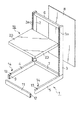
左右の支柱(2)(3)の前面には、多数のスリット(2a)(3a)が、左右2列として上下方向に並べて穿設され、各支柱(2)(3)の下端には、前後方向を向くベース脚(4)(5)の後端が止着されている。
左右の支柱(2)(3)のスリット(2a)(3a)には、図示を省略した棚板の下面を支持する前後方向を向くブラケット(同じく図示略)の後端に設けた係止片が係止される。
【0014】
左右の支柱(2)(3)の上端部同士は、上部連結杆(6)により結合され、左右のベース脚(4)(5)の後端部同士は、下部連結杆(7)により結合されている。
【0015】
左右の支柱(2)(3)と上部連結杆(6)と下部連結杆(7)とにより囲まれた空間には、方形のパネル(8)がはめ込まれている。
【0016】
ベース脚(4)(5)の内側面の前端部には、上下2個の取付孔(9)が穿設され、また、ベース脚(4)(5)の下面の前後2カ所には、高さ調節用のアジャスタ(10)が設けられている。
【0017】
ベース脚(4)(5)の取付孔(9)に、キックプレート(11)の左右両側面に突設した下向係止片(12)を係合することにより、キックプレート(11)が取り付けられている。
【0018】
ベース脚(4)(5)の上面の前端部には、ほぼ正方形の係止孔(13)が穿設され、係止孔(13)の前縁には、図2に拡大して示す係止具(14)が係止されている。
【0019】
図2に示すように、係止具(14)は、ほぼ水平の方形の挿入片(15)の左右両側縁の後端部から側面視ほぼ台形状の起立片(16)(17)を立設してなり、起立片(16)(17)の前半部と挿入片(15)との間には、後向きのスリット(18)が形成されている。
図5に示すように、左右の起立片(16)(17)の間の間隔は、後述するベース棚(19)の側片(23)の板厚の2倍より大としてある。
【0020】
係止具(14)は、その挿入片(15)を係止孔(13)内に挿入し、スリット(18)を係止孔(13)の前縁に臨ませて、そのまま前方に移動させて、スリット(18)の後端部に係止孔(13)の前縁部を当接させることにより、起立片(16)(17)の前部の下面と挿入片(15)とによりベース脚(4)(5)の上片(4a)(5a)を挾持した状態で、係止孔(13)に係合される(図6参照)。
【0021】
ベース棚(19)は、方形の基板(20)の4辺を下向きに折り曲げ、かつ基板(20)の下面の前後2カ所に、断面形が上向きコ字状をなす左右方向を向く補強部材(21)(21)を固着したものである。
【0022】
ベース棚(19)は、図4〜図6に示すように、前側の補強部材(21)の前面を、左右の係止具(14)の内側の起立片(17)の後端に当接させ、基板(20)の後端より垂下する後片(22)を、支柱(2)(3)の下端部の前面に当接させるとともに、基板(20)の両側端より垂下する左右の側片(23)を、係止具(14)の左右の起立片(16)(17)間に嵌合させた状態で、左右のベース脚(4)(5)上に載置される。
この際、起立片(17)の後端は、前側の補強部材(21)の前面に当接しているので、係止具(14)が係止孔(13)から抜け出すおそれはない。
【0023】
この実施形態によれば、ベース脚(4)(5)の上面に1個の係止孔(13)を穿設するだけでよいので、ベース脚(4)(5)を低コストで製造することができ、かつ係止孔(13)に取り付けられる係止具(14)は小型の部材であるため、製造コストを低くすることができるとともに、不使用時における係止具(14)の保管用スペースを小さくすることができ、保管に便利である。
【0024】
また、係止具(14)に左右1対の起立片(16)(17)を設けてあり、かつ左右の起立片(16)(17)の間隔は、ベース棚(19)の側片(23)の板厚の2倍より大きいので、図7及び図8に示す変形例の商品陳列棚(24)のように、支柱(2)(3)(2')とベース脚(4)(5)(4')を3個として、これらを左右に並べ、隣り合うベース脚(4)(5)(4')の間に、2枚のベース棚(19)(19)を並べて架設する場合には、左右のベース棚(19)(19)における近接する側片(23)(23)を左右の起立片(16)(17)の間に嵌合すればよいので、新たな係止具(14)は不要となり、2枚のベース棚(19)(19)を容易に架設できる。
【0025】
なお、必要に応じ、支柱(2)(3)とベース脚(4)(5)の数を更に増やして、3枚以上のベース棚(19)を、隣り合うベース脚(4)(5)の間に容易に並べて架設することができる。
【0026】
また、係止孔(13)をベース脚(4)(5)の後部に穿設して、後部の補強部材(21)の前面を起立片(17)の後端面に当接させたり、あるいは、ベース脚(4)(5)の前後2カ所に係止孔(13)を穿設して、各係止孔(13)に係止具(14)を取り付けて、各係止具(14)の起立片(17)の後端面に前後の補強部材(21)の前面を当接させてもよい。
【0027】
次に、本発明の第2の実施形態である商品陳列棚(24)について、図9〜図11を参照しながら説明する。
なお、第1の実施形態と同一の部材には同一の符号を付すに止めて、その詳細な説明は省略する。
【0028】
第1の実施形態では、ベース脚(4)(5)の上面の前端部に係止孔(13)が穿設されているが、本実施形態では、図10に示すように係止具(25)が係止される係止孔(26)は、ベース脚(4)(5)の上面の後端部に穿設されている。
【0029】
図9に拡大して示すように、係止具(25)は、挿入片(27)と起立片(28)(29)からなるとともに、起立片(28)(29)と挿入片(27)との間にはスリット(30)が形成されており、起立片(28)(29)の上端部には、下向きの係合溝(31)(31)が形成されている。
【0030】
ベース棚(19)の基板(20)の下面における後端部には、前向片(32)の後端部から下方に垂下する垂下片(33)が連設された係合部材(34)の前向片(32)が固着されている。
ベース棚(19)は、図10及び図11に示すように、垂下片(33)を、左右の係止具(25)の内側の起立片(29)の係合溝(31)に上方から嵌合させ、基板(20)の後片(22)を支柱(2)(3)の下端部の前面に当接させるとともに、基板(20)の左右の側片(23)を、係止具(25)の左右の起立片(28)(29)間に嵌合させた状態で、左右のベース脚(4)(5)上に載置される。
この際、起立片(28)の係合溝(31)には垂下片(33)が嵌合されているので、係止具(25)の前後方向への移動が制限され、係止具(25)が係止孔(26)から抜け出すおそれはない。
【0031】
本実施形態においては、係止孔(26)をベース脚(4)(5)の上面の後端部に穿設したが、ベース脚(4)(5)の前端部に係止孔(26)を穿設して、この係止孔(26)に係止具(25)を取り付けたり、係止孔(26)をベース脚(4)(5)の前後2カ所に穿設して、計4つの係止具(25)を用いてベース棚(19)をベース脚(4)(5)に載置してもよい。
【0032】
また、ベース棚(19)とは別体の係合部材(34)を基板(20)の下面に固着することによって基板(20)の下面に垂下片(33)を設けているが、ベース棚(19)の基板(20)の両側部を下方に切り起こすか、または側板(23)を内向きに切り起こすことによって垂下片(33)を形成してもよい。
【0033】
さらに、図示は省略したが、図7及び図8に示す第1の実施形態の変形例のように、3本の支柱(2)(3)(2’)とベース脚(4)(5)(4’)を並設した商品陳列棚とすることもできる。
【0034】
【発明の効果】
(A) 請求項1記載の発明によると、係止具をベース脚の係止孔の前縁に係合させた後、ベース棚をベース脚上に載置するだけで、簡単に組み付け作業が完了し、ねじ止め作業等の必要がない。
ベース脚の上面には、1個の係止孔を穿設するだけでよいので、ベース脚を低コストで製造でき、係止孔に取り付けられる係止具は小型の部材であるため、製造コストを低くすることができるとともに、不使用時における係止具の保管用スペースを小さくすることができる。
また、ベース棚が正規の位置に装着されると、ベース棚の前後、左右の移動が確実に阻止されるとともに、係止具の後端がベース棚の補強部材の前面に当接することにより、係止具が係止孔から抜け出すのを確実に防止することができる。
【0035】
(B) 請求項2記載の発明によると、上記(A)と同様の作用及び効果を奏することができる他に、スリットの後端部が係止孔の前縁に当接した状態で、起立片の係合溝にベース棚の下面に突設された垂下片が嵌合することにより、係止具の後方への移動だけでなく、前方への移動も阻止され、係止具が係止孔から抜け出すのをより確実に防止することができるとともに、係止具の前後方向のがたつき等も防止することができる。
【0036】
(C) 請求項3記載の発明によると、係止具に左右1対の起立片を設け、かつ左右の起立片の間隔を、ベース棚の側片の板厚の2倍より大きくしたので、例えば、支柱とベース脚を3個に増やして、これらを左右に並べて、隣り合うベース脚の間に2枚のベース棚を並べて架設する場合に、左右のベース棚における近接する側片を左右の起立片の間に嵌合すればよいので、新たな係止具を設ける必要はなく、2枚のベース棚を容易に架設することができる。また、支柱とベース脚の数を更に増やすことにより、多数のベース棚を容易に並べて架設することができる。
【0037】
(D) 請求項4記載の発明によると、左右のベース脚の間に、キックプレートを簡単かつ確実に取り付けることができるとともに、ベース脚の前端部の左右方向の移動が阻止され、商品陳列棚全体の強度が向上する。
【図面の簡単な説明】
【図1】本発明の一実施形態の分解斜視図である。
【図2】同じく、左側のベース脚の前部の拡大分解斜視図である。
【図3】同じく、組立てた状態における商品陳列棚の斜視図である。
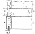
【図4】図3のIV−IV線における拡大縦断面図である。
【図5】図4のV−V線における拡大縦断面図である。
【図6】図5のVI−VI線における縦断面図である。
【図7】本発明の変形例の斜視図である。
【図8】図7に示す変形例の図5と同様の拡大横断面図である。
【図9】本発明の第2の実施形態である商品陳列装棚に用いられる、係止具の拡大斜視図である。
【図10】同じく、商品陳列装棚の要部の拡大縦断面図である。
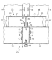
【図11】図10のXI-XI線における拡大縦断面図である。
【符号の説明】
(1)商品陳列棚
(2)(2')(3)支柱
(2a)(3a)スリット
(4)(4')(5)ベース脚
(4a)(5a)上片
(6)上部連結杆
(7)下部連結杆
(8)パネル
(9)取付孔
(10)アジャスタ
(11)キックプレート
(12)下向係合片
(13)係止孔
(14)係止具
(15)挿入片
(16)(17)起立片
(18)スリット
(19)ベース棚
(20)基板
(21)補強部材
(22)後片
(23)側片
(24)商品陳列棚
(25)係止具
(26)係止孔
(27)挿入片
(28)(29)起立片
(30)スリット
(31)係合溝
(32)前向片
(33)垂下片
(34)係合部材[0001]
BACKGROUND OF THE INVENTION
The present invention relates to a merchandise display shelf installed in a supermarket, a home center, a convenience store, or the like.
[0002]
[Prior art]
In this type of merchandise display shelf, means for supporting the base shelf so as not to move in the horizontal direction on the base legs extending forward from the lower ends of the pair of right and left columns is, for example, Japanese Utility Model Publication No. 62-11497. There are some which are disclosed in the official gazette and Japanese Utility Model Publication No. 54-7498.
[0003]
In the former, a plurality of L-shaped engagement holes provided on the inner side surfaces of the left and right base legs are engaged with the downward engagement pieces formed at both ends of the connecting rod facing in the left-right direction, and are attached to both ends of the connecting rod. By holding a reinforcing rod facing in the left-right direction fixed to the lower surface of the base shelf placed on the base leg by a pair of front and rear gripping pieces facing upward, the movement of the base shelf in the front-rear direction is prevented, By fitting inward engagement protrusions formed at the front ends of both holding pieces into engagement holes formed at the front and rear surfaces of the reinforcing rod, the base shelf is prevented from moving in the left-right direction. .
[0004]
The latter is a side that hangs down from both side edges of the base shelf when the standing piece that protrudes upward from the upper surface of the base leg is screwed from the inner surface of the base leg and the base shelf is placed on the base leg. When the inward edge of the piece abuts the outer surface of the upright piece, the base shelf is prevented from moving in the left-right direction, and the front end of the reinforcing rod facing the left-right direction fixed to the lower surface of the base shelf is By abutting the protrusion on the upper surface, the base shelf is prevented from moving forward.
[0005]
[Problems to be solved by the invention]
However, in the above-mentioned former structure, not only a large number of L-shaped engagement holes have to be drilled in the base leg, but also a pair of front and rear provided at the both ends of the connecting rods that connect the left and right base legs. This requires a large number of members such as a holding piece, which complicates the structure and increases the manufacturing cost.
[0006]
In the latter case, since the upright piece must be screwed, the work is troublesome, and there is a problem that assembly work is troublesome.
[0007]
In view of the above-mentioned problems of the prior art, the present invention can be easily assembled with a minimum number of parts without requiring work such as screwing, and after the base shelf is mounted. An object of the present invention is to provide a product display device that can prevent parts from falling off and can reliably prevent the back and forth and right and left movement of a base shelf.
[0008]
[Means for Solving the Problems]
According to the present invention, the above problem is solved as follows.
(1) In a product display shelf in which hollow base legs facing in the front-rear direction are provided at the lower portions of the support columns provided on the left and right sides and a base shelf is installed between the upper surfaces of the left and right base legs, An upright standing piece protrudes from both the left and right sides of the rear end portion of the substantially horizontal insertion piece having a size that can be inserted into the locking hole, and is inserted into the front portion of the standing piece. Inserting the insertion piece in the locking tool in which a backward slit is formed between the locking hole into the locking hole and fitting the slit into the front edge of the locking hole, A base shelf with a lower surface opened and a reinforcing member facing the left and right direction fixed to the lower surface is installed on the upper surfaces of the left and right base legs, and the front surface of the reinforcing member is brought into contact with the rear surface of the locking tool. In both cases, the rear surface of the base shelf is brought into contact with the lower front surface of the column, and the base shelf The side pieces extending downward from the right side edge, disposed on the outside of the right or left standing piece in fastener.
[0009]
(2) In a product display shelf in which hollow base legs facing in the front-rear direction are provided at the lower portions of the support columns provided on the left and right sides, and a base shelf is installed between the upper surfaces of the left and right base legs, A stop hole is drilled, and an upright standing piece with a downward engagement groove formed on the upper end is projected on both the left and right sides of the rear end of the substantially horizontal insertion piece that can be inserted into the locking hole. And insert the insertion piece in the locking tool in which a rearward slit is formed between the front part of the standing piece and the insertion piece into the locking hole, and fit the slit into the front edge of the locking hole. By fitting, the locking tool is attached to the locking hole, the bottom surface opens, and the base shelf with hanging pieces protruding from the bottom surface is installed on the upper surfaces of the left and right base legs, and the hanging pieces are engaged. Fit the groove into the groove from above and bring the rear surface of the base shelf into contact with the lower front surface of the column. The side pieces extending downward from the side edge of the left and right base shelves, is disposed outside the right or left standing piece in fastener.
[0010]
(3) In the above item (1) or (2), the interval between the left and right standing pieces in the locking tool is made larger than twice the plate thickness of the side piece of the base shelf.
[0011]
(4) In any one of the above items (1) to (3), a mounting hole is formed in the front end portion of the inner side surface of the left and right base legs, and the left and right directions have the same length as the distance between the left and right base legs. The kick plates are attached between the front end portions of the left and right base legs by engaging downwardly engaging pieces projecting from the left and right end faces of the kick plate facing to the attachment holes of the left and right base legs.
[0012]
DETAILED DESCRIPTION OF THE INVENTION
Hereinafter, a commodity display shelf (1) according to a first embodiment of the present invention will be described with reference to FIGS.
[0013]
A number of slits (2a) and (3a) are drilled in the vertical direction in the left and right columns in the front of the left and right columns (2) and (3), and at the bottom of each column (2) and (3), The rear ends of the base legs (4) and (5) facing the front-rear direction are fixed.
In the slits (2a) and (3a) of the left and right support columns (2) and (3), a locking piece provided at the rear end of a bracket (also not shown) that supports the lower surface of the shelf board (not shown) facing forward and backward. Is locked.
[0014]
The upper ends of the left and right support columns (2) and (3) are joined by an upper connecting rod (6), and the rear ends of the left and right base legs (4) and (5) are joined by a lower connecting rod (7). Has been.
[0015]
A rectangular panel (8) is fitted in the space surrounded by the left and right support columns (2) (3), the upper connecting rod (6), and the lower connecting rod (7).
[0016]
At the front end of the inner side surface of the base legs (4) and (5), two upper and lower mounting holes (9) are formed, and at the two front and rear positions on the lower surface of the base legs (4) and (5), An adjuster (10) for height adjustment is provided.
[0017]
By engaging the downward locking pieces (12) protruding from the left and right sides of the kick plate (11) into the mounting holes (9) of the base legs (4) and (5), the kick plate (11) It is attached.
[0018]
A substantially square locking hole (13) is formed at the front end of the upper surface of the base legs (4) and (5), and the front edge of the locking hole (13) is shown in FIG. The stopper (14) is locked.
[0019]
As shown in FIG. 2, the locking device (14) stands upright trapezoidal upright pieces (16), (17) in side view from the rear ends of the left and right side edges of the substantially horizontal rectangular insertion piece (15). A rearward slit (18) is formed between the front half of the upright pieces (16) and (17) and the insertion piece (15).
As shown in FIG. 5, the distance between the left and right upright pieces (16) and (17) is set to be larger than twice the plate thickness of the side piece (23) of the base shelf (19) described later.
[0020]
The locking tool (14) has its insertion piece (15) inserted into the locking hole (13) and moved forward with the slit (18) facing the front edge of the locking hole (13). The lower edge of the front part of the upright pieces (16) and (17) and the insertion piece (15) In the state of holding the upper pieces (4a) and (5a) of the legs (4) and (5), they are engaged with the locking holes (13) (see FIG. 6).
[0021]
The base shelf (19) has four sides of a square substrate (20) bent downward, and in two front and rear positions on the lower surface of the substrate (20), a reinforcing member (right and left) whose cross-sectional shape is an upward U-shape ( 21) (21) is fixed.
[0022]
As shown in FIGS. 4 to 6, the base shelf (19) abuts the front surface of the front reinforcing member (21) with the rear end of the upright piece (17) inside the left and right latches (14). The rear piece (22) that hangs down from the rear end of the substrate (20) is brought into contact with the front surface of the lower end portion of the support columns (2) and (3), and the left and right sides hang down from both ends of the substrate (20). The piece (23) is placed on the left and right base legs (4) and (5) in a state where the piece (23) is fitted between the left and right standing pieces (16) and (17) of the locking tool (14).
At this time, since the rear end of the standing piece (17) is in contact with the front surface of the front reinforcing member (21), there is no possibility that the locking tool (14) comes out of the locking hole (13).
[0023]
According to this embodiment, since only one locking hole (13) has to be formed on the upper surface of the base legs (4) and (5), the base legs (4) and (5) are manufactured at low cost. Since the locking tool (14) that can be attached to the locking hole (13) is a small member, the manufacturing cost can be reduced and the locking tool (14) can be stored when not in use. The space for use can be reduced and it is convenient for storage.
[0024]
In addition, a pair of left and right upright pieces (16) and (17) are provided on the locking tool (14), and the distance between the left and right upright pieces (16) and (17) is set to the side piece of the base shelf (19) ( 23) is larger than twice the plate thickness, so that the columns (2) (3) (2 ′) and the base legs (4) (4) (like the product display shelf (24) of the modification shown in FIGS. 5) Three (4 ') are arranged side by side, and two base shelves (19) and (19) are installed side by side between adjacent base legs (4), (5) and (4'). In this case, the adjacent side pieces (23) and (23) in the left and right base shelves (19) and (19) may be fitted between the left and right upright pieces (16) and (17), so that new locking The tool (14) is not required, and the two base shelves (19) (19) can be easily installed.
[0025]
In addition, if necessary, the number of support columns (2) (3) and base legs (4) (5) is further increased, so that three or more base shelves (19) can be connected to adjacent base legs (4) (5). Can be installed side by side easily.
[0026]
Further, a locking hole (13) is formed in the rear part of the base leg (4) (5) so that the front surface of the rear reinforcing member (21) is brought into contact with the rear end surface of the upright piece (17), or The locking holes (13) are drilled at the two front and rear positions of the base legs (4) and (5), and the locking tools (14) are attached to the locking holes (13). The front surfaces of the front and rear reinforcing members (21) may be brought into contact with the rear end surface of the standing piece (17).
[0027]
Next, a merchandise display shelf (24) according to a second embodiment of the present invention will be described with reference to FIGS.
The same members as those in the first embodiment are designated by the same reference numerals, and detailed description thereof is omitted.
[0028]
In the first embodiment, a locking hole (13) is formed in the front end portion of the upper surface of the base legs (4) and (5). In this embodiment, as shown in FIG. A locking hole (26) for locking 25) is formed at the rear end of the upper surface of the base legs (4) and (5).
[0029]
As shown in FIG. 9 in an enlarged manner, the locking device (25) includes an insertion piece (27) and upright pieces (28) (29), and the upright pieces (28) (29) and the insertion piece (27). A slit (30) is formed between them, and downward engaging grooves (31) (31) are formed at the upper ends of the upright pieces (28) and (29).
[0030]
An engagement member (34) in which a hanging piece (33) hanging downward from the rear end portion of the forward piece (32) is connected to the rear end portion of the lower surface of the base plate (20) of the base shelf (19). The forward facing piece (32) is fixed.
As shown in FIG. 10 and FIG. 11, the base shelf (19) has a hanging piece (33) inserted into the engaging groove (31) of the upright piece (29) inside the right and left locking tools (25) from above. The rear piece (22) of the board (20) is brought into contact with the front surface of the lower end of the support (2) (3), and the left and right side pieces (23) of the board (20) It is mounted on the left and right base legs (4) and (5) in a state of being fitted between the left and right standing pieces (28) and (29) of (25).
At this time, since the hanging piece (33) is fitted in the engaging groove (31) of the standing piece (28), the movement of the locking tool (25) in the front-rear direction is restricted, and the locking tool ( There is no risk of 25) coming out of the locking hole (26).
[0031]
In this embodiment, the locking hole (26) is formed in the rear end of the upper surface of the base legs (4) and (5), but the locking hole (26 is formed in the front end of the base legs (4) and (5). ) And attaching the locking tool (25) to the locking hole (26), or drilling the locking hole (26) in two places before and after the base legs (4) and (5), The base shelf (19) may be placed on the base legs (4) and (5) using a total of four locking tools (25).
[0032]
In addition, a hanging piece (33) is provided on the lower surface of the substrate (20) by fixing an engaging member (34) separate from the base shelf (19) to the lower surface of the substrate (20). The drooping piece (33) may be formed by cutting both sides of the substrate (20) of (19) downward or by cutting the side plate (23) inward.
[0033]
Further, although not shown in the drawings, as in the modification of the first embodiment shown in FIGS. 7 and 8, the three columns (2) (3) (2 ′) and the base legs (4) (5) (4 ') can also be used as a product display shelf.
[0034]
【The invention's effect】
(A) According to the first aspect of the present invention, after the locking tool is engaged with the front edge of the locking hole of the base leg, the base shelf can be simply mounted on the base leg, and the assembly work can be easily performed. Completed and no need for screwing.
Since only one locking hole needs to be drilled on the upper surface of the base leg, the base leg can be manufactured at low cost, and the locking tool attached to the locking hole is a small member. As well as the storage space for the locking tool when not in use.
In addition, when the base shelf is mounted at a regular position, the movement of the front and rear and left and right of the base shelf is surely prevented, and the rear end of the locking tool comes into contact with the front surface of the reinforcing member of the base shelf, It is possible to reliably prevent the locking tool from coming out of the locking hole.
[0035]
(B) According to the invention described in
[0036]
(C) According to the invention described in
[0037]
(D) According to the invention described in claim 4, the kick plate can be easily and reliably attached between the left and right base legs, and the movement of the front end portion of the base legs in the left-right direction is prevented. Overall strength is improved.
[Brief description of the drawings]
FIG. 1 is an exploded perspective view of an embodiment of the present invention.
FIG. 2 is an enlarged exploded perspective view of the front part of the left base leg.
FIG. 3 is a perspective view of the commodity display shelf in the assembled state.
4 is an enlarged vertical sectional view taken along line IV-IV in FIG. 3;
5 is an enlarged longitudinal sectional view taken along line VV in FIG. 4. FIG.
6 is a longitudinal sectional view taken along line VI-VI in FIG.
FIG. 7 is a perspective view of a modified example of the present invention.
8 is an enlarged cross-sectional view similar to FIG. 5 of the modified example shown in FIG.
FIG. 9 is an enlarged perspective view of a locking tool used for a merchandise display shelf according to a second embodiment of the present invention.
FIG. 10 is an enlarged longitudinal sectional view of the main part of the commodity display shelf.
11 is an enlarged longitudinal sectional view taken along line XI-XI in FIG.
[Explanation of symbols]
(1) Product display shelf
(2) (2 ') (3) Prop
(2a) (3a) Slit
(4) (4 ') (5) Base leg
(4a) (5a) Upper piece
(6) Upper connection rod
(7) Lower connection rod
(8) Panel
(9) Mounting hole
(10) Adjuster
(11) Kick plate
(12) Downward engagement piece
(13) Locking hole
(14) Locking tool
(15) Insertion piece
(16) (17) Standing piece
(18) Slit
(19) Base shelf
(20) Board
(21) Reinforcing member
(22) Rear piece
(23) Side piece
(24) Product display shelf
(25) Locking tool
(26) Locking hole
(27) Insertion piece
(28) (29) Standing piece
(30) Slit
(31) Engagement groove
(32) Forward piece
(33) Drooping piece
(34) Engagement member
Claims (4)
前記ベース脚の上面に係止孔を穿設し、前記係止孔に挿入しうる寸法のほぼ水平な挿入片の後端部の左右両側部に、上向きの起立片を突設し、かつ、起立片の前部と挿入片との間に後向きのスリットを形成した係止具における前記挿入片を係止孔に挿入するとともに、スリットを係止孔の前縁部に嵌合することにより、係止孔に係止具を取り付け、下面が開口するとともに、下面に左右方向を向く補強部材が固着されたベース棚を左右のベース脚の上面に架設して、前記補強部材の前面を係止具の後面に当接させるともに、ベース棚の後面を支柱の下部の前面に当接させ、かつ、ベース棚の左右の側端から垂下する側片を、係止具における左右いずれかの起立片の外側に配設したことをことを特徴とする商品陳列棚。In the product display shelf where hollow base legs facing in the front-rear direction are provided at the bottom of the support columns provided on the left and right, and a base shelf is installed between the upper surfaces of the left and right base legs,
A locking hole is drilled on the upper surface of the base leg, and upright standing pieces protrude from left and right sides of the rear end of a substantially horizontal insertion piece of a size that can be inserted into the locking hole; and By inserting the insertion piece into the locking hole in the locking tool in which a rearward slit is formed between the front part of the standing piece and the insertion piece, and fitting the slit into the front edge of the locking hole, Attach a locking tool to the locking hole, open a bottom surface, and attach a base shelf with a reinforcing member fixed in the left-right direction on the bottom surface to the upper surface of the left and right base legs, and lock the front surface of the reinforcing member The side piece hanging from the left and right side edges of the base shelf is either left or right standing on the locking device. A merchandise display shelf that is arranged outside the door.
前記ベース脚の上面に係止孔を穿設し、前記係止孔に挿入しうる寸法のほぼ水平な挿入片の後端部の左右両側部に、上端部に下向きの係合溝が形成された上向きの起立片を突設し、かつ、起立片の前部と挿入片との間に後向きのスリットを形成した係止具における前記挿入片を係止孔に挿入するとともに、スリットを係止孔の前縁部に嵌合することにより、係止孔に係止具を取り付け、下面が開口するとともに、下面に垂下片が突設されたベース棚を左右のベース脚の上面に架設して、前記垂下片を係合溝に上方から嵌合させるとともに、ベース棚の後面を支柱の下部の前面に当接させ、かつ、ベース棚の左右の側端から垂下する側片を、係止具における左右いずれかの起立片の外側に配設したことを特徴とする商品陳列棚。In the product display shelf where hollow base legs facing in the front-rear direction are provided at the bottom of the support columns provided on the left and right, and a base shelf is installed between the upper surfaces of the left and right base legs,
A locking hole is formed in the upper surface of the base leg, and a downward engaging groove is formed in the upper end portion on both left and right sides of the rear end portion of the substantially horizontal insertion piece that can be inserted into the locking hole. In addition to inserting the insertion piece into the locking hole and locking the slit, the locking tool has a rearward slit formed between the front part of the standing piece and the insertion piece. By fitting to the front edge of the hole, a locking tool is attached to the locking hole, the bottom surface opens, and a base shelf with a hanging piece protruding from the bottom surface is installed on the top surfaces of the left and right base legs. The hanging piece is fitted into the engaging groove from above, the rear surface of the base shelf is brought into contact with the lower front surface of the support column, and the side pieces hanging from the left and right side ends of the base shelf A merchandise display shelf, which is disposed on the outside of either of the right and left standing pieces.
Priority Applications (1)
| Application Number | Priority Date | Filing Date | Title |
|---|---|---|---|
| JP2000137506A JP4594490B2 (en) | 2000-05-10 | 2000-05-10 | Product display shelf |
Applications Claiming Priority (1)
| Application Number | Priority Date | Filing Date | Title |
|---|---|---|---|
| JP2000137506A JP4594490B2 (en) | 2000-05-10 | 2000-05-10 | Product display shelf |
Publications (2)
| Publication Number | Publication Date |
|---|---|
| JP2001314289A JP2001314289A (en) | 2001-11-13 |
| JP4594490B2 true JP4594490B2 (en) | 2010-12-08 |
Family
ID=18645271
Family Applications (1)
| Application Number | Title | Priority Date | Filing Date |
|---|---|---|---|
| JP2000137506A Expired - Fee Related JP4594490B2 (en) | 2000-05-10 | 2000-05-10 | Product display shelf |
Country Status (1)
| Country | Link |
|---|---|
| JP (1) | JP4594490B2 (en) |
Cited By (1)
| Publication number | Priority date | Publication date | Assignee | Title |
|---|---|---|---|---|
| KR101576506B1 (en) * | 2014-05-20 | 2015-12-11 | (주)태진이엔지 | Load rack |
Families Citing this family (2)
| Publication number | Priority date | Publication date | Assignee | Title |
|---|---|---|---|---|
| JP2019076619A (en) * | 2017-10-26 | 2019-05-23 | 株式会社オカムラ | Panel device |
| JP6916087B2 (en) * | 2017-10-26 | 2021-08-11 | 株式会社オカムラ | Standing device |
Citations (6)
| Publication number | Priority date | Publication date | Assignee | Title |
|---|---|---|---|---|
| JPS5557371U (en) * | 1978-10-14 | 1980-04-18 | ||
| JPS56471U (en) * | 1979-06-15 | 1981-01-06 | ||
| JPS57102357U (en) * | 1980-12-15 | 1982-06-23 | ||
| JPH02119825U (en) * | 1989-03-14 | 1990-09-27 | ||
| JPH0650558U (en) * | 1992-11-10 | 1994-07-12 | 株式会社岡村製作所 | Bottom shelf holding device in display shelf |
| JPH09262161A (en) * | 1996-03-28 | 1997-10-07 | Okamura Corp | Merchandise display rack |
-
2000
- 2000-05-10 JP JP2000137506A patent/JP4594490B2/en not_active Expired - Fee Related
Patent Citations (6)
| Publication number | Priority date | Publication date | Assignee | Title |
|---|---|---|---|---|
| JPS5557371U (en) * | 1978-10-14 | 1980-04-18 | ||
| JPS56471U (en) * | 1979-06-15 | 1981-01-06 | ||
| JPS57102357U (en) * | 1980-12-15 | 1982-06-23 | ||
| JPH02119825U (en) * | 1989-03-14 | 1990-09-27 | ||
| JPH0650558U (en) * | 1992-11-10 | 1994-07-12 | 株式会社岡村製作所 | Bottom shelf holding device in display shelf |
| JPH09262161A (en) * | 1996-03-28 | 1997-10-07 | Okamura Corp | Merchandise display rack |
Cited By (1)
| Publication number | Priority date | Publication date | Assignee | Title |
|---|---|---|---|---|
| KR101576506B1 (en) * | 2014-05-20 | 2015-12-11 | (주)태진이엔지 | Load rack |
Also Published As
| Publication number | Publication date |
|---|---|
| JP2001314289A (en) | 2001-11-13 |
Similar Documents
| Publication | Publication Date | Title |
|---|---|---|
| JPS63210403A (en) | Retainer | |
| JP4594490B2 (en) | Product display shelf | |
| JP4388508B2 (en) | Storage rack | |
| US4355585A (en) | Shelf builders | |
| JPH08238131A (en) | Frame device for laboratory table | |
| JP2998064B2 (en) | Cabinet structure in a modular shelf | |
| JP4388507B2 (en) | Storage rack | |
| JP4673501B2 (en) | Shelf board support structure | |
| JP7126258B2 (en) | Bracket, product display shelf device, and bracket mounting method | |
| JP3623901B2 (en) | Stable support device for self-standing partition device | |
| JP4236341B2 (en) | Showcase product shelf | |
| JP4355904B2 (en) | Display shelf | |
| JPH0342844Y2 (en) | ||
| US20070184723A1 (en) | Modular storage system, components therefor, storage method & kit | |
| JP4070183B2 (en) | Product display shelf | |
| JP2003116682A (en) | Display shelf unit | |
| JPH0130126Y2 (en) | ||
| JPH04128632U (en) | Installation device for screen panels on desks | |
| JPH09135758A (en) | End cover fitting structure for utensile for displaying flat article | |
| JPH0662847U (en) | Object shelf fall prevention device | |
| JP3416811B2 (en) | Shelf equipment | |
| JP4418223B2 (en) | Table with shelf | |
| JPH10155614A (en) | Showcase | |
| JP2002095559A (en) | Structure for supporting base shelves in commodity display shelf | |
| JP3186880U (en) | Product display shelf |
Legal Events
| Date | Code | Title | Description |
|---|---|---|---|
| A621 | Written request for application examination |
Free format text: JAPANESE INTERMEDIATE CODE: A621 Effective date: 20070418 |
|
| A521 | Written amendment |
Free format text: JAPANESE INTERMEDIATE CODE: A523 Effective date: 20070423 |
|
| A977 | Report on retrieval |
Free format text: JAPANESE INTERMEDIATE CODE: A971007 Effective date: 20100907 |
|
| TRDD | Decision of grant or rejection written | ||
| A01 | Written decision to grant a patent or to grant a registration (utility model) |
Free format text: JAPANESE INTERMEDIATE CODE: A01 Effective date: 20100914 |
|
| A01 | Written decision to grant a patent or to grant a registration (utility model) |
Free format text: JAPANESE INTERMEDIATE CODE: A01 |
|
| A61 | First payment of annual fees (during grant procedure) |
Free format text: JAPANESE INTERMEDIATE CODE: A61 Effective date: 20100917 |
|
| FPAY | Renewal fee payment (event date is renewal date of database) |
Free format text: PAYMENT UNTIL: 20130924 Year of fee payment: 3 |
|
| R150 | Certificate of patent or registration of utility model |
Ref document number: 4594490 Country of ref document: JP Free format text: JAPANESE INTERMEDIATE CODE: R150 Free format text: JAPANESE INTERMEDIATE CODE: R150 |
|
| R250 | Receipt of annual fees |
Free format text: JAPANESE INTERMEDIATE CODE: R250 |
|
| R250 | Receipt of annual fees |
Free format text: JAPANESE INTERMEDIATE CODE: R250 |
|
| R250 | Receipt of annual fees |
Free format text: JAPANESE INTERMEDIATE CODE: R250 |
|
| R250 | Receipt of annual fees |
Free format text: JAPANESE INTERMEDIATE CODE: R250 |
|
| R250 | Receipt of annual fees |
Free format text: JAPANESE INTERMEDIATE CODE: R250 |
|
| R250 | Receipt of annual fees |
Free format text: JAPANESE INTERMEDIATE CODE: R250 |
|
| S533 | Written request for registration of change of name |
Free format text: JAPANESE INTERMEDIATE CODE: R313533 |
|
| R350 | Written notification of registration of transfer |
Free format text: JAPANESE INTERMEDIATE CODE: R350 |
|
| LAPS | Cancellation because of no payment of annual fees |