JP4594310B2 - Method and apparatus for transmission control in Ethernet passive optical network - Google Patents
Method and apparatus for transmission control in Ethernet passive optical network Download PDFInfo
- Publication number
- JP4594310B2 JP4594310B2 JP2006526432A JP2006526432A JP4594310B2 JP 4594310 B2 JP4594310 B2 JP 4594310B2 JP 2006526432 A JP2006526432 A JP 2006526432A JP 2006526432 A JP2006526432 A JP 2006526432A JP 4594310 B2 JP4594310 B2 JP 4594310B2
- Authority
- JP
- Japan
- Prior art keywords
- word
- transmitter
- data
- received
- physical layer
- Prior art date
- Legal status (The legal status is an assumption and is not a legal conclusion. Google has not performed a legal analysis and makes no representation as to the accuracy of the status listed.)
- Expired - Fee Related
Links
Images


Classifications
-
- H—ELECTRICITY
- H04—ELECTRIC COMMUNICATION TECHNIQUE
- H04L—TRANSMISSION OF DIGITAL INFORMATION, e.g. TELEGRAPHIC COMMUNICATION
- H04L12/00—Data switching networks
- H04L12/28—Data switching networks characterised by path configuration, e.g. LAN [Local Area Networks] or WAN [Wide Area Networks]
-
- H—ELECTRICITY
- H04—ELECTRIC COMMUNICATION TECHNIQUE
- H04Q—SELECTING
- H04Q11/00—Selecting arrangements for multiplex systems
- H04Q11/0001—Selecting arrangements for multiplex systems using optical switching
- H04Q11/0062—Network aspects
- H04Q11/0067—Provisions for optical access or distribution networks, e.g. Gigabit Ethernet Passive Optical Network (GE-PON), ATM-based Passive Optical Network (A-PON), PON-Ring
-
- H—ELECTRICITY
- H04—ELECTRIC COMMUNICATION TECHNIQUE
- H04B—TRANSMISSION
- H04B10/00—Transmission systems employing electromagnetic waves other than radio-waves, e.g. infrared, visible or ultraviolet light, or employing corpuscular radiation, e.g. quantum communication
- H04B10/50—Transmitters
- H04B10/564—Power control
-
- H—ELECTRICITY
- H04—ELECTRIC COMMUNICATION TECHNIQUE
- H04J—MULTIPLEX COMMUNICATION
- H04J3/00—Time-division multiplex systems
- H04J3/16—Time-division multiplex systems in which the time allocation to individual channels within a transmission cycle is variable, e.g. to accommodate varying complexity of signals, to vary number of channels transmitted
- H04J3/1694—Allocation of channels in TDM/TDMA networks, e.g. distributed multiplexers
-
- H—ELECTRICITY
- H04—ELECTRIC COMMUNICATION TECHNIQUE
- H04L—TRANSMISSION OF DIGITAL INFORMATION, e.g. TELEGRAPHIC COMMUNICATION
- H04L12/00—Data switching networks
- H04L12/28—Data switching networks characterised by path configuration, e.g. LAN [Local Area Networks] or WAN [Wide Area Networks]
- H04L12/40—Bus networks
- H04L12/403—Bus networks with centralised control, e.g. polling
-
- H—ELECTRICITY
- H04—ELECTRIC COMMUNICATION TECHNIQUE
- H04J—MULTIPLEX COMMUNICATION
- H04J3/00—Time-division multiplex systems
- H04J3/02—Details
- H04J3/06—Synchronising arrangements
- H04J3/0635—Clock or time synchronisation in a network
- H04J3/0682—Clock or time synchronisation in a network by delay compensation, e.g. by compensation of propagation delay or variations thereof, by ranging
-
- H—ELECTRICITY
- H04—ELECTRIC COMMUNICATION TECHNIQUE
- H04Q—SELECTING
- H04Q11/00—Selecting arrangements for multiplex systems
- H04Q11/0001—Selecting arrangements for multiplex systems using optical switching
- H04Q11/0062—Network aspects
- H04Q11/0066—Provisions for optical burst or packet networks
Description
本発明は、イーサネット(登録商標)受動光ネットワークの設計に関する。特に詳しくは、本発明は、伝送を制御して、イーサネット(登録商標)受動光ネットワーク内の異なるノードからのレーザのノイズにより発生する干渉を低減する方法および装置に関する。 The present invention relates to the design of Ethernet passive optical networks. More particularly, the present invention relates to a method and apparatus for controlling transmission to reduce interference caused by laser noise from different nodes in an Ethernet passive optical network.
ますます増えつつあるインターネットトラフィックに歩調を合わせるために、光ファイバおよび対応する光伝送設備を幅広く配置して、基幹ネットワークの容量を大幅に増加している。しかしながら、このような基幹ネットワーク容量の増加は、対応するアクセスネットワーク容量における増加と一致していない。デジタル加入者回線(DSL)およびケーブルモデム(CM)等のブロードバンドソリューションを用いたとしても、現在のアクセスネットワークが提供する限定された帯域幅では、高帯域幅をエンドユーザに提供する際に深刻な障害が発生している。 In order to keep pace with the increasing Internet traffic, a wide range of optical fibers and corresponding optical transmission facilities have been deployed to greatly increase the capacity of the backbone network. However, such an increase in backbone network capacity is not consistent with a corresponding increase in access network capacity. Even with broadband solutions such as Digital Subscriber Line (DSL) and Cable Modem (CM), the limited bandwidth provided by current access networks is severe in providing high bandwidth to end users. A failure has occurred.
現在開発中の異なる技術のうち、イーサネット(登録商標)受動光ネットワーク(EPON)は、次世代アクセスネットワークとして最も良い候補の1つである。EPONは、ユビキタスイーサネット(登録商標)技術を安価な受動光学素子と組み合わせたものである。従って、費用対効果の高い、高容量の受動光学素子を用いて、イーサネット(登録商標)の簡易性および拡張性を提供するものである。特に、高帯域幅の光ファイバにより、EPONは、ブロードバンド音声、データおよびビデオトラフィックに同時に対応することができる。このような一体型サービスを、DSLまたはCM技術で提供することは難しい。また、EPONがインターネットプロトコル(IP)トラフィックにさらに適しているのは、イーサネット(登録商標)フレームが大きさの異なるネイティブIPパケットを直接カプセル化することができるのに対し、ATM受動光ネットワーク(APON)は大きさが決まっているATMセルを用いているので、結果としてパケットの断片化および再構築が必要となるからである。 Of the different technologies currently under development, the Ethernet passive optical network (EPON) is one of the best candidates for next generation access networks. EPON combines Ubiquitous Ethernet technology with inexpensive passive optical elements. Accordingly, the simplicity and expandability of Ethernet® is provided using cost-effective, high-capacity passive optical elements. In particular, high bandwidth optical fiber allows EPON to simultaneously support broadband voice, data and video traffic. It is difficult to provide such an integrated service with DSL or CM technology. EPON is also more suitable for Internet Protocol (IP) traffic because Ethernet frames can directly encapsulate native IP packets of different sizes, whereas ATM passive optical networks (APON ) Uses ATM cells having a predetermined size, and as a result, fragmentation and reconstruction of packets are required.
一般に、EPONは、ネットワークの“最初の1マイル”に用いられている。これにより、サービスプロバイダの中央局と、業務または個人加入者との間に接続性を構成する。理論的には、最初の1マイルは、多数の加入者にサービスを提供する中央局を備える、ポイントツーマルチポイントネットワークである。ツリートポロジをEPONに用いることができる。1本のファイバで中央局を受動光分配器と接続して、下流側の光信号を分割して加入者に分配して、加入者からの上流側の光信号を合成する(図1を参照)。 Generally, EPON is used for the “first mile” of the network. This establishes connectivity between the service provider's central office and business or individual subscribers. Theoretically, the first mile is a point-to-multipoint network with a central office serving a large number of subscribers. A tree topology can be used for EPON. The central office is connected to the passive optical distributor with a single fiber, the downstream optical signal is divided and distributed to the subscribers, and the upstream optical signals from the subscribers are combined (see FIG. 1). ).
EPON内の伝送は一般に、光加入者線端局装置(OLT)と光ネットワーク装置(ONU)との間で行われる(図2を参照)。OLTは一般に中央局に常駐し、光アクセスネットワークを地下基幹に接続する。これは一般に、インターネットサービスプロバイダ(ISP)またはローカル公衆網に属する外部ネットワークである。ONUを、CURBまたはエンドユーザの位置のいずれかに配置することができ、ブロードバンド音声データおよびビデオサービスを提供することができる。ONUは一般に、1×N受動光カプラに接続する。NはONUの数である。受動光カプラは一般に、1つの光リンクを介してOLTに接続している(それ以上のONUを収容するために、多数の光スプリッタ/カプラをカスケードし得ることに留意されたい)。この構成により、EPONが必要とするファイバの本数とハードウェアの量とを大幅に節約することができる。 Transmission within an EPON is generally performed between an optical subscriber line terminal equipment (OLT) and an optical network equipment (ONU) (see FIG. 2). The OLT generally resides at the central office and connects the optical access network to the underground trunk. This is typically an external network belonging to an Internet service provider (ISP) or local public network. The ONU can be located at either the CURB or the end user location and can provide broadband voice data and video services. The ONU is typically connected to a 1 × N passive optical coupler. N is the number of ONUs. Passive optical couplers are typically connected to the OLT via one optical link (note that multiple optical splitters / couplers can be cascaded to accommodate more ONUs). With this configuration, the number of fibers and the amount of hardware required by the EPON can be greatly saved.
EPON内の通信は、下流側トラフィック(OLTからONU)と上流側トラフィック(ONUからOLT)とに分けられる。下流側方向では、1×N受動光カプラの一斉送信の性質のために、OLTによる下流側データフレーム一斉送信が全ONUに届いて、続いて宛て先ONUが抽出することができる。上流側方向では、ONUがチャネル容量およびリソースを共有する必要があるのは、受動光カプラをOLTと接続しているリンクが1つしかないからである。 Communication within the EPON is divided into downstream traffic (OLT to ONU) and upstream traffic (ONU to OLT). In the downstream direction, due to the broadcast nature of the 1 × N passive optical coupler, the downstream data frame broadcast by the OLT reaches all ONUs, and the destination ONU can subsequently extract. In the upstream direction, ONUs need to share channel capacity and resources because there is only one link connecting the passive optical coupler to the OLT.
それに対応して、EPONは一般に、あるアービトレーション機構を用いて、データの衝突を防止し、上流側ファイバチャネル容量を公平に共有するようにしている。これは、伝送ウインドウ(タイムスロット)を各ONUに割り当てることにより、行われる。各タイムスロットは、数個のイーサネット(登録商標)パケットを伝送することができる。ONUは一般に、そのタイムスロットに達するまで、加入者から受信するパケットを緩衝する。そのタイムスロットに達したならば、ONUは、保存した全フレームをOLTまで、全チャネル速度で“バーストする”。 Correspondingly, EPON generally uses a certain arbitration mechanism to prevent data collisions and share upstream Fiber Channel capacity fairly. This is done by assigning a transmission window (time slot) to each ONU. Each time slot can carry several Ethernet packets. An ONU typically buffers packets received from a subscriber until that time slot is reached. Once that time slot is reached, the ONU “bursts” all stored frames to the OLT at the full channel rate.
EPONを設計する際の問題の1つは、異なるONUからのレーザのノイズによって発生するデータ伝送に伴う干渉である。ONU内のレーザ送信機は、データ伝送を行わなくても自然放出ノイズを発生する。従って、ONUのレーザが伝送タイムスロットの間にある場合は、その自然放出ノイズにより、別のONUが送信したデータの信号の品質を損なう場合がある。複数の近くにあるONUからのノイズが離れたところにあるONUからのデータ信号と干渉する場合に、この障害が悪化する。 One of the problems in designing an EPON is the interference associated with data transmission caused by laser noise from different ONUs. The laser transmitter in the ONU generates spontaneous emission noise without performing data transmission. Therefore, when the ONU laser is in the transmission time slot, the spontaneous emission noise may impair the quality of the data signal transmitted by another ONU. This obstacle is exacerbated when the noise from multiple nearby ONUs interferes with data signals from remote ONUs.
データを送信しない場合にレーザをオフにすることにより、レーザのノイズの問題を回避することができる。これは、データリンク層で生成して、物理層で受信したレーザ制御信号を用いることにより、達成することができる。 By turning off the laser when no data is transmitted, the problem of laser noise can be avoided. This can be achieved by using laser control signals generated at the data link layer and received at the physical layer.
しかしながら、制御信号をいくつかのサブレイヤにわたって送信すると、層またはサブレイヤが、その直近の層またはサブレイヤにだけ信号を送信するという、基本的な層リング原理を犯すことになる。ONUでは、データリンク層が、媒体アクセス制御(MAC)クライアントサブレイヤと、マルチポイントMAC制御サブレイヤと、MACサブレイヤとを含むことに留意されたい。また、物理層は、照合調整サブレイヤ、ギガビット・メディア・インデペンデント・インターフェース(GMII)と、物理符号化サブレイヤ(PCS)と、物理媒体接続(PMA)サブレイヤと、物理媒体依存(PMD)サブレイヤとを含む。この環境では、レーザ制御信号を通常MAC制御サブレイヤにより生成して、PMDサブレイヤを受信することにより、MAC制御サブレイヤとPMDサブレイヤとの間のサブレイヤをバイパスする。 However, transmitting a control signal across several sublayers violates the basic layer ring principle that a layer or sublayer transmits signals only to its immediate layer or sublayer. Note that in an ONU, the data link layer includes a medium access control (MAC) client sublayer, a multipoint MAC control sublayer, and a MAC sublayer. In addition, the physical layer includes a matching adjustment sublayer, a gigabit media independent interface (GMII), a physical coding sublayer (PCS), a physical medium connection (PMA) sublayer, and a physical medium dependent (PMD) sublayer. including. In this environment, the laser control signal is generated by the normal MAC control sublayer and the PMD sublayer is received to bypass the sublayer between the MAC control sublayer and the PMD sublayer.
従って、複数のサブレイヤにわたって制御信号を送信することなく、ONUの効率的に制御する方法および装置が必要となる。 Therefore, there is a need for a method and apparatus for efficiently controlling an ONU without transmitting control signals across multiple sublayers.
(概要)
本発明の一実施形態は、中央ノードと、データリンク層および物理層を実行する少なくとも1つのリモートノードとを含むイーサネット(登録商標)受動光ネットワーク内の伝送制御を容易にするシステムを提供する。動作の間、システムは、リモートノードのデータリンク層から通信した、データワードまたはアイドルワードであるワードをリモートノードの物理層で受信することにより、開始する。システムは次に、送信機がワードを送信可能になる前に、ワードを所定量の時間遅延することにより、送信機をオンまたはオフにする時間を生成する。システムはまた、受信したワードの内容に基づいて送信機をオンまたはオフにする。
(Overview)
One embodiment of the present invention provides a system that facilitates transmission control in an Ethernet passive optical network that includes a central node and at least one remote node that implements a data link layer and a physical layer. During operation, the system begins by receiving at the remote node's physical layer a word that is a data word or idle word communicated from the remote node's data link layer. The system then generates time to turn the transmitter on or off by delaying the word by a predetermined amount of time before the transmitter can transmit the word. The system also turns the transmitter on or off based on the contents of the received word.
本実施形態の変形例では、受信したワードの内容に基づいて送信機をオンまたはオフにすることが、送信機の電源が現在オフであり、かつ、受信したワードがデータワードである場合に送信機をオンにすることを含む。 In a variation of this embodiment, turning the transmitter on or off based on the content of the received word is transmitted when the transmitter is currently powered off and the received word is a data word Including turning on the machine.
本実施形態の変形例では、受信したワードの内容に基づいて送信機をオンまたはオフにすることが、送信機の電源が現在オンであり、かつ、連続する受信したアイドルワードの数が所定の数以上の場合に、送信機をオフにすることを含む。 In a variation of this embodiment, turning the transmitter on or off based on the content of the received word means that the transmitter is currently on and the number of consecutive received idle words is a predetermined number. In the case of more than a number, including turning off the transmitter.
本実施形態の変形例では、ワードを所定量の時間遅延することが、先入れ先出し(FIFO)待ち行列のワードをバッファして、FIFO待ち行列のバッファした各ワードをFIFO待ち行列の先頭に向かって定期的にずらして、FIFO待ち行列の先頭のワードを定期的に削除することを含む。 In a variation of this embodiment, delaying a word by a predetermined amount of time buffers words in a first-in first-out (FIFO) queue and periodically forwards each buffered word in the FIFO queue toward the beginning of the FIFO queue. And periodically deleting the first word of the FIFO queue.
本実施形態の変形例では、システムが、レーザターンオン時間、自動利得制御(AGC)時間およびデータ・クロックリカバリ(CDR)時間に基づいて、ワードを遅延する時間量を決定する。 In a variation of this embodiment, the system determines the amount of time to delay the word based on the laser turn-on time, automatic gain control (AGC) time, and data clock recovery (CDR) time.
本実施形態の変形例では、受信したワードがデータワードの場合は、システムが、物理層が受信した現在のデータフレームの直後に別のデータフレームをデータリンク層が一時的に送信しないようにすることにより、データフレームの間に挿入するアイドルワードを十分な数にする。 In a variation of this embodiment, if the received word is a data word, the system prevents the data link layer from temporarily transmitting another data frame immediately after the current data frame received by the physical layer. Thus, a sufficient number of idle words are inserted between data frames.
本実施形態の変形例では、物理層で受信した連続するアイドルワードの数が十分にある場合は、システムが、データリンク層に別のデータフレームを物理層へ送信させる。 In a modification of this embodiment, if there are enough consecutive idle words received at the physical layer, the system causes the data link layer to transmit another data frame to the physical layer.
当業者が本発明を利用し用いることができるように、特定の適用例およびその要件を背景として、以下に説明する。開示した実施形態に対する各種の変形例は、当業者にとって容易に明らかになるであろう。そして、ここで定義する一般的な原理を、本発明の精神及び範囲から逸脱しない範囲で(例えば、一般的な受動光ネットワーク(PON)アーキテクチャ)、他の実施形態および適用例に適用することもできる。従って、本発明は、示した実施形態に限定されるものではなく、ここに開示した原理および特徴に一致した最も広い範囲に基づくものである。 In order to enable those skilled in the art to utilize and use the present invention, the following description is given in the context of specific applications and their requirements. Various modifications to the disclosed embodiments will be readily apparent to those skilled in the art. The general principles defined herein may also be applied to other embodiments and applications without departing from the spirit and scope of the present invention (eg, general passive optical network (PON) architecture). it can. Accordingly, the present invention is not limited to the embodiments shown, but is based on the widest scope consistent with the principles and features disclosed herein.
この詳細な説明に記載のデータ構造および手順を一般に、コンピュータ読取可能記憶媒体に保存する。これは、コンピュータシステムが用いるコードおよび/またはデータを格納する任意の装置または媒体であっても良い。これに限定しないが、特定用途向けIC(ASIC)、フィールドプログラマブルゲートアレイ(FPGA)、半導体メモリ、ディスクドライブ磁気テープ、CD(コンパクトディスク)およびDVD(デジタル多目的ディスクまたはデジタルビデオディスク)等の磁気および光記憶装置、伝送媒体埋め込みコンピュータ命令信号(信号を変調した搬送波があるもの、またはないもの)を含む。 The data structures and procedures described in this detailed description are generally stored on a computer readable storage medium. This may be any device or medium that stores code and / or data used by a computer system. Magnetics such as, but not limited to, application specific IC (ASIC), field programmable gate array (FPGA), semiconductor memory, disk drive magnetic tape, CD (compact disk) and DVD (digital multipurpose disk or digital video disk) Optical storage devices, including transmission medium embedded computer command signals (with or without a carrier wave modulating the signal).
受動光ネットワークトポロジ
図1は、中央局および多数の加入者が、光ファイバおよび受動光分配器を介してともに接続している、受動光ネットワークを示している(従来技術)。図1に示すように、多数の加入者が、光ファイバおよび受動光分配器102を介して中央局101と接続している。受動光分配器102をエンドユーザ位置の近傍に配置することができるので、初期ファイバ設置コストを最小限にすることができる。中央局101を、インターネットサービスプロバイダ(ISP)が運営する都市圏ネットワーク等の外部ネットワーク103と接続することができる。図1ではツリートポロジを示しているが、受動光ネットワークは、リングまたはバス等の他のトポロジに基づくこともできることに留意されたい。
Passive Optical Network Topology FIG. 1 shows a passive optical network in which a central office and a number of subscribers are connected together via optical fibers and passive optical distributors (prior art). As shown in FIG. 1, a large number of subscribers are connected to the central office 101 via optical fibers and passive
EPON内での通常動作モード
図2は、通常動作モードでのEPONを示す(従来技術)。ONUを任意の時にEPON内に接続できるようにするために、EPONは一般に、2つの動作モードを有している。通常動作モードおよびディスカバリ(初期化)モードである。通常動作モードは、通常の上流側データ送信を含み、OLTが全ての初期化されたONUに送信機械を割り当てることを可能にする。
Normal Operation Mode Figure 2 in the EPON shows EPON in normal operation mode (prior art). In order to allow an ONU to be connected within an EPON at any time, an EPON generally has two modes of operation. A normal operation mode and a discovery (initialization) mode. The normal mode of operation includes normal upstream data transmission and allows the OLT to assign a transmission machine to all initialized ONUs.
図2に示すように、下流側の方向では、OLT201が下流側データをONU211、ONU212およびONU213に一斉送信する。全ONUは同じコピーの下流側データを受信する間に、各ONUは、自身のその対応するユーザに宛てたデータのみを選択的に転送する。それぞれ、ユーザ221、ユーザ222、ユーザ223である。
As shown in FIG. 2, in the downstream direction, the
上流側の方向では、ONUのサービスレベルの契約により、OLT201は始めに、伝送ウインドウをスケジュール設定して、各ONUに割り当てる。その伝送タイムスロットではない場合は、ONUは一般に、そのユーザから受信したデータをバッファする。そのスケジュール設定した伝送タイムスロットになった場合は、ONUは、そのバッファしたユーザデータを割り当てられた伝送タイムスロット内で送信する。
In the upstream direction, the
全ONUがOLTのスケジュール設定に従って順番に上流側データを送信するので、上流側リンクの容量を効率的に利用することができる。しかしながら、適切にスケジュール設定を行うには、OLTは、新規に加入したONUを検出して初期化する必要がある。検出の間は、OLTは、ONUの往復伝搬時間(RTT)、その媒体アクセス(MAC)アドレス、そのサービスレベルの契約等の、伝送スケジュール設定に重要な情報を収集しても良い(いくつかの場合では、サービスレベルの契約をすでにOLTがわかっている場合もあることに留意されたい)。 Since all ONUs transmit upstream data in order according to the OLT schedule setting, the capacity of the upstream link can be used efficiently. However, in order to appropriately set the schedule, the OLT needs to detect and initialize a newly joined ONU. During detection, the OLT may collect important information for transmission scheduling, such as the ONU round trip time (RTT), its medium access (MAC) address, its service level agreement, etc. Note that in some cases, the OLT may already know the service level contract).
一般的なイーサネット(登録商標)の要件
図3は、ブリッジイーサネット(登録商標)セグメントを示す(従来技術)。IEEE802規格により、イーサネット(登録商標)セグメントはポイントツーポイントモードで動作できるようになっている。ポイントツーポイントイーサネット(登録商標)セグメントでは、リンクが、2つのホスト、つまり、ホストとイーサネット(登録商標)ブリッジとを接続している。ポイントツーポイントモードは、ギガビットイーサネット(登録商標)等の交換イーサネット(登録商標)での動作の共通した形式である。
General Ethernet Requirements FIG. 3 shows a bridged Ethernet segment (prior art). According to the IEEE 802 standard, the Ethernet segment can operate in a point-to-point mode. In the point-to-point Ethernet segment, the link connects two hosts, a host and an Ethernet bridge. The point-to-point mode is a common form of operation on switched Ethernet (registered trademark) such as Gigabit Ethernet (registered trademark).
複数のイーサネット(登録商標)ホストが互いに通信する必要がある場合は、イーサネット(登録商標)ブリッジは一般に、複数のポイントツーポイントイーサネット(登録商標)セグメント間を接続して切り替えて、セグメント間通信が行えるようにしている。図3に示すように、イーサネット(登録商標)ブリッジ310は、複数のポートを有している。ポイントツーポイントセグメント321および322はそれぞれ、ポート311および312に接続している。共用媒体セグメント323は、ポート313に接続している。セグメント322上のホストがセグメント321上のホストにデータフレームを送信する場合は、その宛て先イーサネット(登録商標)(MAC)アドレスに従って、イーサネット(登録商標)ブリッジ310によりポート312からポート311へデータフレームを転送する。一般に、ブリッジは、フレームを到着したポートへ戻すことはない。 When multiple Ethernet hosts need to communicate with each other, Ethernet bridges typically connect and switch between multiple point-to-point Ethernet segments to enable inter-segment communication. I can do it. As shown in FIG. 3, the Ethernet (registered trademark) bridge 310 has a plurality of ports. Point-to-point segments 321 and 322 are connected to ports 311 and 312 respectively. The shared media segment 323 is connected to the port 313. When a host on the segment 322 transmits a data frame to a host on the segment 321, the data frame is transmitted from the port 312 to the port 311 by the Ethernet bridge 310 according to the destination Ethernet (MAC) address. Forward. In general, the bridge does not return frames to the port that arrived.
EPON内でのポイントツーポイントエミュレーション(PtPE)
EPON内では、ONUからOLTへの上流側伝送がポイントツーポイント通信なので、EPONの動作は理想的には、IEEE802規格が定義するポイントツーポイントイーサネット(登録商標)動作に準拠している。しかしながら、EPONアーキテクチャは、ブリッジポイントツーポイントイーサネット(登録商標)の要件を自動的に満たすわけではない。EPON上流側リンクを1つのイーサネット(登録商標)ブリッジポートに接続して、上流側トラフィックを全てそのポートで受信する場合は、同じEPON上の別のONUに接続したユーザは、互いに通信することができなくなる。OLT内に位置するイーサネット(登録商標)ブリッジが上流側データを切り替えないのは、同じポートで受信したからである。このような構成により、同じEPON内のONU間でデータトラフィックが、層3(ネットワーク層)で処理されることになってしまい、EPON外に常駐する設備によって切り替えられることになってしまう(例えば、OLTが接続しているIPルータである)。これは、EPON内トラフィックを出力するには大変非効率的なやり方である。
Point-to-point emulation within EPON (PtPE)
Since the upstream transmission from the ONU to the OLT is point-to-point communication within the EPON, the EPON operation ideally conforms to the point-to-point Ethernet (registered trademark) operation defined by the IEEE 802 standard. However, the EPON architecture does not automatically meet the bridge point-to-point Ethernet requirements. When an EPON upstream link is connected to one Ethernet bridge port and all upstream traffic is received on that port, users connected to another ONU on the same EPON can communicate with each other. become unable. The reason why the Ethernet (registered trademark) bridge located in the OLT does not switch the upstream data is that it is received at the same port. With such a configuration, data traffic between ONUs in the same EPON will be processed at layer 3 (network layer) and will be switched by equipment resident outside the EPON (for example, IP router to which the OLT is connected). This is a very inefficient way to output intra-EPON traffic.
この問題を解決して、EPONを他のイーサネット(登録商標)ネットワークとシームレスに統合するためには、EPON媒体に所属する装置は理想的には、ポイントツーポイント媒体をエミュレートすることができるサブレイヤをさらに有する。このサブレイヤを、照合調整サブレイヤ(RS)と呼ぶ。このエミュレーションサブレイヤはデータリンク層の下層に常駐して、IEEE802.3規格が規定する既存のイーサネット(登録商標)MAC動作を保存する。エミュレーション層の動作は、イーサネット(登録商標)フレームに、各ONUに一意のタグをタグ付けすることに基づいている。これらのタグは論理リンクID(LLID)と呼ばれるもので、各フレームの前のプリアンブルとして配置する。 To solve this problem and integrate EPON seamlessly with other Ethernet networks, devices belonging to EPON media are ideally sublayers that can emulate point-to-point media. It has further. This sublayer is referred to as a matching adjustment sublayer (RS). This emulation sublayer resides below the data link layer and preserves existing Ethernet MAC operations as defined by the IEEE 802.3 standard. The operation of the emulation layer is based on tagging each ONU with a unique tag in the Ethernet frame. These tags are called logical link IDs (LLIDs) and are arranged as a preamble before each frame.
図4Aは、EPON内のポイントツーポイントエミュレーションでの下流側トラフィック伝送を示す(従来技術)。PtPEモードでは、OLT400は複数のMACポート(インターフェース)を有している。それぞれ、ONUに対応している。MACポート431からイーサネット(登録商標)フレームを下流側に送信する場合は、OLT400の照合調整サブレイヤ440は、MACポート431に対応付けられているLLID461を挿入する。フレームを、受動光カプラを介して全ONUに一斉送信するが、一致するLLIDを有する、ONU内に位置する照合調整サブレイヤモジュール(この例では、LLID461を有するONU451)だけが、フレームを受け取って、そのMAC層に渡して、さらに検証する。他のONU内(LLID462を有するONU452およびLLID463を有するONU453)のMAC層は、そのフレームを受け取ることはない。従って、宛て先ONUに対してだけ、ポイントツーポイントリンクでフレームを送信したかのように見える。
FIG. 4A shows downstream traffic transmission with point-to-point emulation in EPON (prior art). In the PtPE mode, the OLT 400 has a plurality of MAC ports (interfaces). Each corresponds to an ONU. When transmitting an Ethernet (registered trademark) frame from the
図4Bは、EPON内のポイントツーピントエミュレーションでの上流側トラフィック伝送を示す(従来技術)。上流側方向では、ONU451は、その割り当てられたLLID461を各送信したフレームのプリアンブルに挿入する。従って、OLT400の照合調整サブレイヤ440は、フレームをMACポート431に流すことになる。
FIG. 4B shows upstream traffic transmission with point-to-focus emulation in EPON (prior art). In the upstream direction, the
複数のONU間での上流リンクの共有
EPONでは、複数のONUが通常、1つのアップリンクを共有して上流側データを送信しているのは、光分配器とOLTとの間にはリンクが1つしかないからである。このタイムシェア伝送を協働するために、OLTは、伝送タイムスロットを各ONUに割り当てている。このようなタイムシェア伝送方法を実施する際の問題の1つは、ONUからのレーザのノイズによって発生する、あるONUから送信したデータとの干渉である。
Upstream link sharing among multiple ONUs In an EPON, multiple ONUs usually share one uplink and transmit upstream data because there is a link between the optical distributor and the OLT. Because there is only one. In order to cooperate with this time share transmission, the OLT assigns a transmission time slot to each ONU. One of the problems in implementing such a time share transmission method is interference with data transmitted from a certain ONU, which is caused by laser noise from the ONU.
電源を入れると、レーザ送信機は、データ伝送を行わなくても自然放出ノイズを生成する。データを送信しないのにONUのレーザ送信機の電源を切らない場合は、複数のONUからの蓄積したノイズが別のONUのデータ伝送と干渉することがある。ノイズを生成しているONUがデータを送信しているONUより近くにある場合は、この干渉が悪化する。 When the power is turned on, the laser transmitter generates spontaneous emission noise without performing data transmission. If the ONU laser transmitter is not turned off without transmitting data, accumulated noise from a plurality of ONUs may interfere with data transmission of another ONU. This interference is exacerbated when the ONU generating the noise is closer to the ONU transmitting the data.
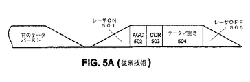
この干渉の問題を解決するアプローチの1つは、伝送スロット間のレーザを遮断することである。図5Aは、EPON内の伝送タイムスロットの構造を示す(従来技術)。伝送タイムスロットに含まれる上流側データバーストは、そのデータペイロードの他にいくつかの部分からなる。図5Aに示すように、タイムスロットは、レーザターンオン期間501と、自動利得制御(AGC)期間502と、クロック・データリカバリ(CDR)期間503と、データ/空きペイロード504と、レーザターンオフ期間505とを含んでも良い。レーザは一般に、瞬間的にオンまたはオフしないので、割り当てられたタイムスロットに対してレーザをオンまたはオフする正確な瞬間を算出する際に、レーザ応答時間を考慮に入れる必要があることに留意されたい。
One approach to solving this interference problem is to block the laser between transmission slots. FIG. 5A shows the structure of transmission time slots in the EPON (prior art). The upstream data burst included in the transmission time slot is composed of several parts in addition to the data payload. As shown in FIG. 5A, the time slot includes a laser turn-on
図5Bは、複数のONUからの上流側データバースト伝送を示す(従来技術)。図5Bに示すように、5つのONU521〜525がOLT500と通信する。ONU521および522がそれぞれ送信した上流側データバースト541および542が、同じアップリンクを共有している。ONU521がデータバースト541を送信している場合は、ONU522〜525内のレーザを遮断する。データ伝送が完了した後で、ONU521はそのレーザを遮断して、ONU522にデータバースト542を送信させる。
FIG. 5B shows upstream data burst transmission from multiple ONUs (prior art). As shown in FIG. 5B, five ONUs 521 to 525 communicate with the
ONU伝送制御
割り当てられたタイムスロットになった時にレーザをオンにして、伝送が完了した時にレーザをオフにするためには、データリンク層からレーザオン/オフ制御信号を単に生成して、物理層に属するレーザを制御する。これは、ONUのローカルクロックは通常、IEEE802.3ah規格に基づいてデータリンク層に常駐しているので、データリンク層が伝送タイムスロットの開始と終了とを検出することが適しているからである。しかしながら、このアプローチでは、層またはサブレイヤが直近の層またはサブレイヤだけに通知するといった、基本的な層リング原理に違反することになる。
ONU transmission control To turn on the laser when the assigned time slot is reached and to turn off the laser when transmission is complete, simply generate a laser on / off control signal from the data link layer to the physical layer. Control the laser to which it belongs. This is because the ONU local clock is usually resident in the data link layer based on the IEEE 802.3ah standard, so it is suitable for the data link layer to detect the start and end of a transmission time slot. . However, this approach violates the basic layer ring principle, where a layer or sublayer only informs the nearest layer or sublayer.
図6は、データリンク層からレーザ制御信号を生成して、物理層に属するレーザを制御することを示す(従来技術)。図6に示すように、OSIモデル層は、物理層612と、データリンク層614と、ネットワーク層616と、トランスポート層618と、セッション層620と、プレゼンテーション層622と、アプリケーション層624とを備える。EPON装置は主に、物理層612およびデータリンク層614内で動作する。IEEE802.3規格に基づいて、EPON内のデータリンク層614は、LLC/MACクライアントサブレイヤ622と、マルチポイントMAC制御サブレイヤ628と、MACサブレイヤ630とを含み、物理層は、照合調整サブレイヤ636と、GMIIインターフェース638と、PCSサブレイヤ640と、PMAサブレイヤ642と、PMDサブレイヤ644と、媒体依存インターフェース(MDI)646と、物理媒体648(光ファイバ)とを含む。特に、物理層装置(PHY)は一般に、PCS、PMAおよびPMDサブレイヤを実行する。
FIG. 6 shows that a laser control signal is generated from the data link layer to control the laser belonging to the physical layer (prior art). As shown in FIG. 6, the OSI model layer includes a physical layer 612, a data link layer 614, a network layer 616, a transport layer 618, a session layer 620, a presentation layer 622, and an application layer 624. . EPON devices operate primarily within the physical layer 612 and the data link layer 614. Based on the IEEE 802.3 standard, the data link layer 614 in the EPON includes an LLC / MAC client sublayer 622, a multipoint MAC control sublayer 628, and a
通常、レーザオン/オフ制御信号650をマルチポイントMAC制御サブレイヤ628で生成して、PMDサブレイヤ644に送信して、レーザをオンオフする。このような信号送信機構は簡単であるが、サブレイヤは一般に、複数の層/サブレイヤにわたって信号を送信しないという層リング原理に違反する。この層リング違反を回避する1つの方法は、複数のサブレイヤにわたって伝送するレーザ制御信号650を除去することである。 Typically, a laser on / off control signal 650 is generated by the multipoint MAC control sublayer 628 and sent to the PMD sublayer 644 to turn the laser on and off. While such a signal transmission mechanism is simple, sublayers generally violate the layer ring principle of not transmitting signals across multiple layers / sublayers. One way to avoid this layer ring violation is to remove the laser control signal 650 that is transmitted across multiple sublayers.
本発明の一実施形態は、データリンク層から受信した各ワードに対する所定量の遅延を物理層に導入する。この方法により、遅延したワードを観察することにより、送信するデータがあるかどうか、物理層が決定を行って、レーザをオンしてデータ伝送を準備する時間を十分有することができる。同様に、データがもうないか、物理層が決定して、これに応じてレーザをオフすることができる。上述の遅延機構を実施するために、先入れ先出し(FIFO)待ち行列を用いて各ワードをバッファすることもできる。 One embodiment of the invention introduces a predetermined amount of delay for each word received from the data link layer into the physical layer. In this way, by observing the delayed word, the physical layer can determine if there is data to send and have enough time to turn on the laser and prepare for data transmission. Similarly, the physical layer can determine if there is more data and the laser can be turned off accordingly. To implement the delay mechanism described above, each word can also be buffered using a first in first out (FIFO) queue.
図7は、本発明の一実施形態による、データリンク層から受信したバッファしたワードに基づいてレーザ送信機を制御する処理を示す。図7の上に示すように、データリンク層から受信したデータは、データフレーム744および750を含む。フレーム744に続くのは、オプションの順方向誤り訂正(FEC)パリティビット746およびパケット間ギャップ(lPG)748のためのスペースである。同様に、フレーム750に続くのは、オプションのFECスペース752およびIPGスペース754である。FECエンコーダをFIFO待ち行列の前または後で実施しても良いことに留意されたい。従って、FECスペース746および752は、前のフレームのFECパリティデータ(FEC符号化をFIFO待ち行列の前で実施する場合)、または空き(FEC符号化をFIFO待ち行列の後で実施する場合)を含むこともある。
FIG. 7 illustrates a process for controlling a laser transmitter based on buffered words received from the data link layer, according to one embodiment of the invention. As shown above in FIG. 7, the data received from the data link layer includes data frames 744 and 750. Following
通常、FECスペースの長さは、前のフレームの長さの関数である。図示の例では、FECスペース746はフレーム744の長さに依存して、FECスペース752はフレーム750の長さに依存している。また、IPGには最小要求サイズがある。例えば、IEEE802.3ah規格により、IPGは12ワード長であることが定義されている。一方、FECはオプションである。
Usually, the length of the FEC space is a function of the length of the previous frame. In the illustrated example,
ワードが物理層に到着した場合は、所定の遅延を有するFIFOバッファ710に格納する。FIFOバッファ710の最後に格納した各ワードを、FIFOバッファ710の先頭に向かって定期的にシフトする。 When the word arrives at the physical layer, it is stored in the FIFO buffer 710 having a predetermined delay. Each word stored at the end of the FIFO buffer 710 is periodically shifted toward the head of the FIFO buffer 710.
いつレーザをオンまたはオフするか決定するために、システムは理想的には、受信したワードの内容を監視する。受信したワードがデータワードで、レーザの電源が入っていない場合は、システムはレーザをオンにする。受信したワードを次に、FIFOバッファ710に格納する。物理層に導入した他の遅延と合わせた場合は、FIFOバッファ710に導入した全遅延は理想的には、レーザターンオン期間740および同期期間742に十分対応する。同期期間742は、自動利得制御(AGC)期間およびクロック・データリカバリ(CDR)期間を含んでもよく、これにより、OLTが上流側データの受信を準備することが可能になることに留意されたい。
In order to determine when to turn the laser on or off, the system ideally monitors the contents of the received word. If the received word is a data word and the laser is not turned on, the system turns on the laser. The received word is then stored in the FIFO buffer 710. When combined with other delays introduced into the physical layer, the total delay introduced into the FIFO buffer 710 ideally corresponds well to the laser turn-on
フレーム744に続くFECスペース746は、フレーム744のFECパリティビットを含む。FIFO待ち行列の前または後でFEC符号化を行っても良いので、データリンク層から受信したFECスペース746は、符号化したFECパリティデータを含んでも良いし、あるいは、空きだけを含んでも良い。FECスペース746の後に、IPGスペース748により、フレーム744(対応するFECスペース768を含む)と、次のフレーム752との間に、確実に最小ギャップが存在するようになる。図7に示す例では、IPGスペース748は、レーザターンオン期間740と同期期間742との合計よりも小さい。従って、IPGスペース748に対応する期間の間は、システムはレーザをオフにしない。
The
同様に、物理層に到着した時に、フレーム750と、その対応するFECスペース752と、IPGスペース754とを、FIFOバッファ710に格納する。物理層が十分に数多くのIPGアイドルワードを受信した時に、システムはレーザをオフにする。データワードがこれらのアイドルワードに続いている場合は、レーザをオンにする時間が十分あるようにするために、レーザをオンにするのに必要な、最小数の連続IPGアイドルワードが、レーザターンオン期間740および/または同期期間742に理想的に十分対応している。
Similarly, when arriving at the physical layer, the
本発明の一実施形態では、システムは、FIFOバッファ710がレーザをオフにするIPGアイドルワードだけを含むようにする必要がある場合もある。このように、レーザをオンにして、次のデータワードの同期時間を用意するのに十分な時間が確実に用意できる。図7に示すように、FECスペース752内の最後のワードがFIFOバッファ710を出た後に、FIFOバッファ710は、IPGアイドルワードだけを含む。この時、システムはレーザをオフにする。これは、レーザターンオフ期間754の後に完全に遮断することである。FECを用いない場合は、フレーム750の最後のデータワードがFIFOバッファ710を出た後でFIFOバッファ710がIPG空きワードだけを含むようになってすぐに、システムはレーザをオフにしても良いことに留意されたい。
In one embodiment of the present invention, the system may need to include only the IPG idle word that the FIFO buffer 710 turns off the laser. In this way, it is possible to reliably prepare a time sufficient to turn on the laser and prepare a synchronization time for the next data word. As shown in FIG. 7, after the last word in
ONUがOLTに近くにある同様の場合は、OLTを、同期のためのデフォルトのAGCおよびCDR時間より小さくする必要がある。従って、このようなONU内のシステムは、FIFOバッファ710に導入した遅延を短縮して、短縮した同期期間を反映させるようにして、伝送オーバーヘッドを小さくしても良い。一般に、システムは、FIFOバッファ710の遅延をもっと柔軟に再構成しても良い。 In similar cases where the ONU is close to the OLT, the OLT needs to be smaller than the default AGC and CDR time for synchronization. Therefore, such a system in the ONU may reduce the transmission overhead by reducing the delay introduced into the FIFO buffer 710 and reflecting the shortened synchronization period. In general, the system may reconfigure the FIFO buffer 710 delay more flexibly.
FECスペースおよびIPGスペースの正確な量を、2つの連続データフレームの間で確保することが重要である。FECスペースおよびIPGスペースの確保は、データリンク層または物理層で行っても良い。第1のシナリオでは、データリンク層(例えば、マルチポイントMAC制御サブレイヤ)が、データフレームの境界を検出して、FECパリティデータおよびIPGに必要なスペースを挿入する。それに応じて、物理層内の伝送制御機構は、いつデータフレームを送信して、いつ伝送を一時停止するかについて、データリンク層に信号を送信する必要はない。 It is important to ensure the correct amount of FEC space and IPG space between two consecutive data frames. The FEC space and the IPG space may be secured in the data link layer or the physical layer. In the first scenario, the data link layer (eg, multipoint MAC control sublayer) detects the boundary of the data frame and inserts the space required for FEC parity data and IPG. Accordingly, the transmission control mechanism in the physical layer need not send a signal to the data link layer as to when to send the data frame and when to pause the transmission.
第2のシナリオでは、データリンク層は、データフレームの間にFECおよびIPGのスペースを挿入しない。その代わり、物理層は、データフレームの境界を検出して、FECおよびIPGに必要なスペースを挿入する。それに応じて、物理層は理想的には、いつデータフレームを送信して、いつ伝送を一時停止するかについて、データリンク層に信号を送信する。 In the second scenario, the data link layer does not insert FEC and IPG spaces between data frames. Instead, the physical layer detects the boundaries of the data frame and inserts the necessary space for FEC and IPG. In response, the physical layer ideally sends a signal to the data link layer about when to send data frames and when to pause transmission.
図8Aは、本発明の一実施形態による、データリンク層にフレームギャップ制御の信号を送信しないで、データリンク層から受信したワードをバッファする処理を示す。システムは、データリンク層からワードを受信することにより開始する(ステップ810)。システムは次に、受信したワードがデータワードまたはアイドルワードかどうか決定する(ステップ812)。 FIG. 8A illustrates a process for buffering words received from the data link layer without transmitting a frame gap control signal to the data link layer according to an embodiment of the present invention. The system begins by receiving a word from the data link layer (step 810). The system then determines whether the received word is a data word or an idle word (step 812).
受信したワードがデータワードの場合は、システムは、アイドル長カウンタを0に設定する(ステップ813)。アイドル長は、連続する空きの数を表し、レーザをオフにする必要があるかどうか決定する際に用いる。システムは次に、レーザがオンになっているかどうか決定する(ステップ814)。レーザがオフの場合は、システムはレーザをオンにする(ステップ816)。そうでない場合は、システムは、FIFOバッファの最初のワードを直接削除するステップに進む(ステップ840)。次に、システムは、FTFOバッファのワードをバッファの先頭に向かってずらして(ステップ841)、受信したデータワードをFIFOバッファの最後に付ける(ステップ842)。システムは次に、データリンク層から次のワードを受信する準備を行う(ステップ810)。 If the received word is a data word, the system sets the idle length counter to 0 (step 813). The idle length represents the number of consecutive vacancies and is used in determining whether the laser needs to be turned off. The system then determines whether the laser is on (step 814). If the laser is off, the system turns on the laser (step 816). If not, the system proceeds to directly delete the first word of the FIFO buffer (step 840). Next, the system shifts the word in the FTFO buffer toward the beginning of the buffer (step 841) and appends the received data word to the end of the FIFO buffer (step 842). The system then prepares to receive the next word from the data link layer (step 810).
受信したワードがアイドルワードの場合は、システムはまず、アイドル長カウンタを1増加する(ステップ820)。次に、システムは、レーザが現在オンになっているか、かつ、レーザターンオン期間と同期期間との合計として定義する遅延限度をアイドル長が超えているかどうか決定する(ステップ852)。両方の条件がともに合っていれば、システムはレーザをオンにして(ステップ854)、FIFOバッファから最初のワードを削除する(ステップ840)。そうでない場合は、システムはレーザの現在の状態を変更しないで、FIFOバッファの最初のワードを削除するステップに進む(ステップ840)。 If the received word is an idle word, the system first increments the idle length counter by 1 (step 820). Next, the system determines whether the laser is currently on and if the idle length exceeds a delay limit defined as the sum of the laser turn-on period and the synchronization period (step 852). If both conditions are met, the system turns on the laser (step 854) and deletes the first word from the FIFO buffer (step 840). If not, the system does not change the current state of the laser and proceeds to delete the first word in the FIFO buffer (step 840).
図8Bは、本発明の一実施形態による、データリンク層にフレームギャップ制御の信号を送信して、データリンク層から受信したワードをバッファする処理を示す。システムは、データリンク層からワードを受信することにより開始する(ステップ860)。システムは次に、受信したワードがデータワードまたはアイドルワードかどうか決定する(ステップ862)。 FIG. 8B illustrates a process for sending a frame gap control signal to the data link layer and buffering words received from the data link layer according to an embodiment of the present invention. The system begins by receiving a word from the data link layer (step 860). The system then determines whether the received word is a data word or an idle word (step 862).
受信したワードがデータワードの場合は、システムは、アイドル長カウンタを0に設定して(ステップ864)、現在受信したフレームの直後に折り返しフレームをデータリンク層が一時的に送信しないようにする(ステップ866)。(IEEE802.3規格に基づいて、キャリア検知信号を“真”に設定することにより、これを達成しても良い。“真”に設定した場合、このキャリア検知信号により、現在のデータフレームがデータリンク層からの伝送を終了して、データリンク層が次のデータフレームを送信しないようにする。)システムは次に、レーザがオンになっているかどうか決定する(ステップ870)。レーザがオフの場合は、システムはレーザをオンにする(ステップ872)。そうでない場合は、システムは、FIFOバッファの最初のワードを削除する(ステップ874)。次に、システムは、FTFOバッファのワードをバッファの先頭に向かってずらして(ステップ876)、受信したデータワードをFIFOバッファの最後に付ける(ステップ878)。システムは次に、データリンク層から次のワードを受信する準備を行う(ステップ860)。 If the received word is a data word, the system sets the idle length counter to 0 (step 864) to prevent the data link layer from temporarily transmitting a return frame immediately after the currently received frame ( Step 866). (This may be achieved by setting the carrier detection signal to “true” based on the IEEE 802.3 standard. When set to “true”, this carrier detection signal causes the current data frame to be data. The transmission from the link layer is terminated so that the data link layer does not transmit the next data frame.) The system then determines whether the laser is on (step 870). If the laser is off, the system turns on the laser (step 872). Otherwise, the system deletes the first word in the FIFO buffer (step 874). Next, the system shifts the word in the FTFO buffer toward the beginning of the buffer (step 876) and appends the received data word to the end of the FIFO buffer (step 878). The system then prepares to receive the next word from the data link layer (step 860).
受信したワードがアイドルワードの場合は、システムはまず、アイドル長カウンタを1増加する(ステップ880)。システムは次に、連続アイドルワードの数(アイドル長)が最小フレームギャップ以上かどうか決定する(ステップ882)。(最小フレームギャップは理想的には、(FECを用いる場合は)FECパリティビットのスペースとデフォルトのIPGスペースとを含むことに留意されたい。)この場合は、システムは、データリンク層に次のフレームを送信させる(ステップ884)。(IEEE802.3規格に基づいて、キャリア検知信号を“誤り”に設定することにより、これを達成しても良い。)そうでない場合は、システムは、レーザが現在オンになっているか、かつ、レーザターンオン期間と同期期間との合計として定義する遅延限度をアイドル長が超えているかどうか決定する(ステップ886)。両方の条件がともに合っていれば、システムはレーザをオフにして(ステップ888)、FIFOバッファの最初のワードを削除する(ステップS874)。そうでない場合は、システムはレーザの現在の状態を変更しないで、FIFOバッファの最初のワードを削除するステップに進む(ステップ874)。 If the received word is an idle word, the system first increments the idle length counter by 1 (step 880). The system then determines whether the number of consecutive idle words (idle length) is greater than or equal to the minimum frame gap (step 882). (Note that the minimum frame gap ideally includes the space for FEC parity bits (if FEC is used) and the default IPG space.) In this case, the system The frame is transmitted (step 884). (This may be accomplished by setting the carrier detect signal to "error" based on the IEEE 802.3 standard.) Otherwise, the system will check if the laser is currently on and It is determined whether the idle length exceeds a delay limit defined as the sum of the laser turn-on period and the synchronization period (step 886). If both conditions are met, the system turns off the laser (step 888) and deletes the first word in the FIFO buffer (step S874). If not, the system does not change the current state of the laser and proceeds to delete the first word in the FIFO buffer (step 874).
本発明の実施形態に関する前述の説明は、説明のためだけになされたものである。それらは、網羅的なものでもなく、本発明を開示した形態を限定するためのものではない。従って、多くの変形例および変更例が当業者にとって明らかであろう。また、上記の開示は、本発明に限定されるものではない。本発明の範囲は、添付の請求の範囲に定められるものである。 The foregoing descriptions of the embodiments of the present invention have been made for the purpose of illustration only. They are not exhaustive and are not intended to limit the present disclosure. Accordingly, many variations and modifications will be apparent to those skilled in the art. Further, the above disclosure is not limited to the present invention. The scope of the present invention is defined by the appended claims.
Claims (21)
リモートノードの該物理層で、該リモートノードの該データリンク層から通信されたワードを受信することであって、該ワードがデータワードまたはアイドルワードであり得る、ことと、
送信機が該ワードを送信可能になる前に、該リモートノードの該物理層で、該ワードを所定量の時間遅延することであって、それにより、該送信機をオンまたはオフにする時間を提供する、ことと、
該受信されたワードの内容に基づいて該送信機をオンまたはオフにすることであって、該送信機をオンにするか、またはオフにするかの決定は、複数のサブレイヤにわたって該データリンク層から該物理層へと制御信号を送信することなく、該リモートノードの該物理層でなされる、ことと
を包含する、方法。A method for controlling transmission in an Ethernet passive optical network (EPON) comprising a central node and at least one remote node running a data link layer and a physical layer, the method comprising:
Receiving at the physical layer of a remote node a word communicated from the data link layer of the remote node, the word being a data word or an idle word;
Delaying the word by a predetermined amount of time at the physical layer of the remote node before the transmitter can transmit the word, thereby allowing time to turn the transmitter on or off To provide,
The decision to turn the transmitter on or off based on the content of the received word, whether to turn the transmitter on or off, is made across the data link layer across multiple sublayers. And at the physical layer of the remote node without transmitting a control signal from the physical layer to the physical layer .
先入れ先出し(FIFO)待ち行列に該ワードをバッファすることと、
該FIFO待ち行列にバッファされた各ワードを、該FIFO待ち行列の先頭に向かって定期的にシフトすることと、
該FIFO待ち行列の先頭のワードを定期的に取り出すことであって、該取り出されたワードは、前記送信機によって送信される、ことと
を含む、請求項1に記載の方法。Delaying the word by a predetermined amount of time,
Buffering the word in a first in first out (FIFO) queue;
Periodically shifting each word buffered in the FIFO queue toward the head of the FIFO queue;
The method of claim 1, comprising periodically retrieving the first word of the FIFO queue, wherein the retrieved word is transmitted by the transmitter.
リモートノードの該物理層で、該リモートノードの該データリンク層から通信されたワードを受信するように構成された受信機構であって、該ワードがデータワードまたはアイドルワードであり得る、受信機構と、
送信機が該ワードを送信可能になる前に、該リモートノードの該物理層で、該ワードを所定量の時間遅延することにより、該送信機をオンまたはオフにする時間を提供するように構成された遅延機構と、
該受信されたワードの内容に基づいて該送信機をオンまたはオフにするように構成された制御機構であって、該送信機をオンにするか、またはオフにするかの決定は、複数のサブレイヤにわたって該データリンク層から該物理層へと制御信号を送信することなく、該リモートノードの該物理層でなされる、制御機構と
を備える、装置。An apparatus for controlling transmission in an Ethernet passive optical network (EPON) comprising a central node and at least one remote node running a data link layer and a physical layer, the apparatus comprising:
A receiving mechanism configured to receive at the physical layer of a remote node a word communicated from the data link layer of the remote node, wherein the word can be a data word or an idle word; ,
Configured to provide time to turn the transmitter on or off by delaying the word by a predetermined amount of time at the physical layer of the remote node before the transmitter can transmit the word Delayed mechanism,
A control mechanism configured to turn the transmitter on or off based on the content of the received word, the decision whether to turn the transmitter on or off is a plurality of A control mechanism made at the physical layer of the remote node without transmitting control signals from the data link layer to the physical layer across sublayers .
先入れ先出し(FIFO)待ち行列に該ワードをバッファすることと、
該FIFO待ち行列にバッファされた各ワードを、該FIFO待ち行列の先頭に向かって定期的にシフトすることと、
該FIFO待ち行列の先頭のワードを定期的に取り出すことであって、該取り出されたワードは、前記送信機によって送信される、ことと
を実行するように構成される、請求項8に記載の装置。While delaying the word by a predetermined amount of time, the delay mechanism
Buffering the word in a first in first out (FIFO) queue;
Periodically shifting each word buffered in the FIFO queue toward the head of the FIFO queue;
9. The method of claim 8, wherein the first word of the FIFO queue is periodically fetched, the fetched word being transmitted by the transmitter. apparatus.
リモートノードの該物理層で、該リモートノードの該データリンク層から通信されたワードを受信することであって、該ワードがデータワードまたはアイドルワードであり得る、ことと、
送信機が該ワードを送信可能になる前に、該リモートノードの該物理層で、該ワードを所定量の時間遅延することであって、それにより、該送信機をオンまたはオフにする時間を提供する、ことと、
該受信されたワードの内容に基づいて該送信機をオンまたはオフにすることであって、該送信機をオンにするか、またはオフにするかの決定は、複数のサブレイヤにわたって該データリンク層から該物理層へと制御信号を送信することなく、該リモートノードの該物理層でなされる、ことと
を包含する、コンピュータ読取可能記憶媒体。A computer readable storage medium storing instructions, wherein when executed by a computer, the computer includes an Ethernet including a central node and at least one remote node executing a data link layer and a physical layer A method of controlling transmission in a passive optical network (EPON), the method comprising:
Receiving at the physical layer of a remote node a word communicated from the data link layer of the remote node, the word being a data word or an idle word;
Delaying the word by a predetermined amount of time at the physical layer of the remote node before the transmitter can transmit the word, thereby allowing time to turn the transmitter on or off To provide,
The decision to turn the transmitter on or off based on the content of the received word, the power link being turned on or off, is made across the data link layer across multiple sublayers. What is done at the physical layer of the remote node without transmitting a control signal from the physical layer to the physical layer .
先入れ先出し(FIFO)待ち行列に該ワードをバッファすることと、
該FIFO待ち行列にバッファされた各ワードを、該FIFO待ち行列の先頭に向かって定期的にシフトすることと、
該FIFO待ち行列の先頭のワードを定期的に取り出すことであって、該取り出されたワードは、前記送信機によって送信される、ことと
を含む、請求項15に記載のコンピュータ読取可能記憶媒体。Delaying the word by a predetermined amount of time,
Buffering the word in a first in first out (FIFO) queue;
Periodically shifting each word buffered in the FIFO queue toward the head of the FIFO queue;
The computer-readable storage medium of claim 15, comprising periodically retrieving the first word of the FIFO queue, wherein the retrieved word is transmitted by the transmitter.
Applications Claiming Priority (3)
| Application Number | Priority Date | Filing Date | Title |
|---|---|---|---|
| US50285603P | 2003-09-15 | 2003-09-15 | |
| US50493603P | 2003-09-23 | 2003-09-23 | |
| PCT/US2004/030365 WO2005029906A1 (en) | 2003-09-15 | 2004-09-14 | Method and apparatus for transmission control in an ethernet passive optical network |
Publications (3)
| Publication Number | Publication Date |
|---|---|
| JP2007521758A JP2007521758A (en) | 2007-08-02 |
| JP2007521758A5 JP2007521758A5 (en) | 2007-09-20 |
| JP4594310B2 true JP4594310B2 (en) | 2010-12-08 |
Family
ID=34381056
Family Applications (1)
| Application Number | Title | Priority Date | Filing Date |
|---|---|---|---|
| JP2006526432A Expired - Fee Related JP4594310B2 (en) | 2003-09-15 | 2004-09-14 | Method and apparatus for transmission control in Ethernet passive optical network |
Country Status (5)
| Country | Link |
|---|---|
| US (1) | US7630639B2 (en) |
| JP (1) | JP4594310B2 (en) |
| KR (1) | KR101028057B1 (en) |
| CN (1) | CN1823547B (en) |
| WO (1) | WO2005029906A1 (en) |
Families Citing this family (29)
| Publication number | Priority date | Publication date | Assignee | Title |
|---|---|---|---|---|
| US7477845B2 (en) * | 2003-08-18 | 2009-01-13 | Teknovus, Inc. | Method and apparatus for reducing data burst overhead in an ethernet passive optical network |
| KR100563657B1 (en) * | 2003-10-21 | 2006-03-23 | 한국전자통신연구원 | Vlan aware shared lan emulation method and device with manageable llid in epon |
| WO2005104738A2 (en) * | 2004-04-28 | 2005-11-10 | Teknovus, Inc. | Method and apparatus for l3-aware switching in an ethernet passive optical network |
| ATE389984T1 (en) * | 2004-12-13 | 2008-04-15 | Alcatel Lucent | PROTOCOL CONFIGURATION PROCEDURES |
| US20070009267A1 (en) * | 2005-06-22 | 2007-01-11 | Crews Darren S | Driving a laser using an electrical link driver |
| KR101242461B1 (en) * | 2005-06-29 | 2013-03-12 | 테크노버스, 인크. | Accomodating Different Clock Frequencies In An Ethernet Passive Optical Network |
| US7818648B2 (en) * | 2005-12-18 | 2010-10-19 | Pmc-Sierra Israel Ltd. | GPON rogue-ONU detection based on error counts |
| JP2007116587A (en) * | 2005-10-24 | 2007-05-10 | Fujitsu Access Ltd | Data transmission system |
| US20070116465A1 (en) * | 2005-11-21 | 2007-05-24 | Tellabs Operations, Inc. | Systems and methods for dynamic alignment of data bursts conveyed over a passive optical net work |
| KR100800688B1 (en) * | 2005-12-26 | 2008-02-01 | 삼성전자주식회사 | Apparatus for controlling optical transmitter in wdm-pon system and method thereof |
| KR100694228B1 (en) * | 2006-02-03 | 2007-03-14 | 삼성전자주식회사 | Epon system and method for reducing rf noise therein |
| CN101132234A (en) * | 2006-08-24 | 2008-02-27 | 上海贝尔阿尔卡特股份有限公司 | Device and method for detecting time slot conflict between optical network units in optical network |
| US8098691B2 (en) * | 2006-12-11 | 2012-01-17 | Broadcom Corporation | Base-band ethernet over point-to-multipoint shared single conductor channel |
| US8873947B2 (en) * | 2007-09-05 | 2014-10-28 | Alcatel Lucent | Method and apparatus for determining fiber characteristics in an optical communication network |
| CN101145884B (en) * | 2007-10-17 | 2012-05-09 | 中兴通讯股份有限公司 | A judgement method for confliction detection in wave division multiplexing service |
| CN101572833B (en) * | 2008-04-28 | 2010-11-10 | 华为技术有限公司 | Method, device and system for transmitting uplink burst data in passive optical network system |
| US8538258B2 (en) * | 2008-05-08 | 2013-09-17 | Alcatel Lucent | Burst-mode data recovery for multi-gigabit passive optical networks |
| JP4351289B1 (en) * | 2008-08-27 | 2009-10-28 | 富士通テレコムネットワークス株式会社 | Subscriber premises communication equipment |
| CN101662702B (en) | 2008-08-27 | 2013-06-26 | 华为技术有限公司 | Time delay control method in passive optical network, optical line terminal and passive optical network |
| US8971390B2 (en) * | 2009-06-15 | 2015-03-03 | Infineon Technologies Ag | Power saving in a communication device |
| US8326152B2 (en) * | 2010-04-15 | 2012-12-04 | Alcatel Lucent | System and method for scheduling timeslots for transmission by optical nodes in an optical network |
| ES2382264B1 (en) | 2010-09-21 | 2013-04-03 | Abengoa Solar New Technologies S.A. | MANAGABLE HYBRID PLANT OF THERMOSOLAR AND PHOTOVOLTAIC TECHNOLOGY AND METHOD OF OPERATION OF THE SAME |
| CN102148761B (en) * | 2011-04-11 | 2013-11-20 | 北京星网锐捷网络技术有限公司 | Communication interface chip, communication equipment and method for realizing energy saving of communication interface |
| EP3407647A1 (en) * | 2011-10-30 | 2018-11-28 | Lantiq Beteiligungs-GmbH & Co.KG | Power saving mode for multi-carrier transmission |
| US9363017B2 (en) * | 2012-07-06 | 2016-06-07 | Qualcomm Incorporated | Methods and systems of specifying coaxial resource allocation across a MAC/PHY interface |
| KR101301656B1 (en) * | 2012-07-20 | 2013-09-16 | 라이트웍스 주식회사 | Method for managing passive optical network remotely |
| US9369212B2 (en) * | 2013-07-22 | 2016-06-14 | Broadcom Corporation | System, method and apparatus for power saving using burst-mode transmission over point-to-point physical connections |
| US20150063812A1 (en) * | 2013-08-27 | 2015-03-05 | Calix, Inc. | Compensator for wavelength drift due to variable laser injection current and temperature in a directly modulated burst mode laser |
| US9306697B2 (en) | 2014-06-30 | 2016-04-05 | Calix, Inc. | System and method of compensating for spectral excursion |
Family Cites Families (11)
| Publication number | Priority date | Publication date | Assignee | Title |
|---|---|---|---|---|
| ES2167399T3 (en) | 1995-09-21 | 2002-05-16 | Cit Alcatel | PROVISION TO AMPLIFY AND COMBINE OPTICAL SIGNS AND METHOD FOR CURRENT TRANSMISSION UP CONDUCTED WITH IT. |
| JP2001111554A (en) | 1999-10-07 | 2001-04-20 | Oki Electric Ind Co Ltd | Customer station equipment for packet communication |
| US20020063932A1 (en) * | 2000-05-30 | 2002-05-30 | Brian Unitt | Multiple access system for communications network |
| FR2818065B1 (en) * | 2000-12-07 | 2003-04-18 | Cit Alcatel | PACKET ROUTER FOR OPTICAL TRANSMISSION NETWORK |
| US20020080444A1 (en) * | 2000-12-22 | 2002-06-27 | David Phillips | Multiple access system for communications network |
| AU2002329216A1 (en) * | 2001-07-10 | 2003-01-29 | Salira Optical Network Systems, Inc | Passive optical network and time division multiplexed system |
| US7245628B2 (en) * | 2001-07-10 | 2007-07-17 | Haixing Shi | Allocation of upstream bandwidth in an ethernet passive optical network |
| JP3820584B2 (en) * | 2002-01-29 | 2006-09-13 | 日本電気株式会社 | COMMUNICATION SYSTEM, COMMUNICATION TERMINAL, SERVER, AND DATA TRANSFER CONTROL PROGRAM |
| KR100419425B1 (en) | 2002-02-01 | 2004-02-21 | 삼성전자주식회사 | Circuit for controlling output of idle pattern in gigabit ethernet - passive optical network |
| US7688843B2 (en) * | 2002-09-13 | 2010-03-30 | Pmc-Sierra Israel Ltd. | Operations method in an ethernet passive optical network that includes a network unit with multiple entities |
| KR100462477B1 (en) * | 2002-12-10 | 2004-12-17 | 한국전자통신연구원 | Apparatus of multipoint control protocol processing in Ethernet PON |
-
2004
- 2004-09-14 WO PCT/US2004/030365 patent/WO2005029906A1/en active Application Filing
- 2004-09-14 JP JP2006526432A patent/JP4594310B2/en not_active Expired - Fee Related
- 2004-09-14 KR KR1020067003189A patent/KR101028057B1/en not_active IP Right Cessation
- 2004-09-14 CN CN2004800201344A patent/CN1823547B/en not_active Expired - Fee Related
- 2004-09-14 US US10/941,356 patent/US7630639B2/en not_active Expired - Fee Related
Also Published As
| Publication number | Publication date |
|---|---|
| US7630639B2 (en) | 2009-12-08 |
| KR101028057B1 (en) | 2011-04-08 |
| US20050058452A1 (en) | 2005-03-17 |
| KR20060081694A (en) | 2006-07-13 |
| JP2007521758A (en) | 2007-08-02 |
| WO2005029906A1 (en) | 2005-03-31 |
| CN1823547B (en) | 2010-08-18 |
| CN1823547A (en) | 2006-08-23 |
Similar Documents
| Publication | Publication Date | Title |
|---|---|---|
| JP4594310B2 (en) | Method and apparatus for transmission control in Ethernet passive optical network | |
| JP4646914B2 (en) | Method and apparatus for reducing data burst overhead in an Ethernet passive optical network | |
| US7289501B2 (en) | Method and apparatus for bandwidth-efficient multicast in ethernet passive optical networks | |
| US7545813B2 (en) | Method and apparatus for registering multiple remote nodes in an ethernet passive optical network | |
| JP4663643B2 (en) | Method and apparatus for transferring packets in an Ethernet passive optical network | |
| KR101242461B1 (en) | Accomodating Different Clock Frequencies In An Ethernet Passive Optical Network | |
| US9106438B2 (en) | Methods and apparatus for extending MAC control messages in EPON | |
| US7664019B2 (en) | Method and apparatus for facilitating differentiated service qualities in an ethernet passive optical network | |
| EP2353228A2 (en) | Method and system for protection switching in ethernet passive optical networks | |
| WO2006124101A2 (en) | Accommodating multiple optical segments in an ethernet passive optical network | |
| CN100534012C (en) | Method and apparatus for reducing data burst overhead in an Ethernet passive optical network | |
| JP2004201013A (en) | Optical subscriber line terminal device, and frame transmission method |
Legal Events
| Date | Code | Title | Description |
|---|---|---|---|
| A521 | Written amendment |
Free format text: JAPANESE INTERMEDIATE CODE: A523 Effective date: 20070806 |
|
| A621 | Written request for application examination |
Free format text: JAPANESE INTERMEDIATE CODE: A621 Effective date: 20070806 |
|
| A131 | Notification of reasons for refusal |
Free format text: JAPANESE INTERMEDIATE CODE: A131 Effective date: 20091110 |
|
| A521 | Written amendment |
Free format text: JAPANESE INTERMEDIATE CODE: A523 Effective date: 20100114 |
|
| A02 | Decision of refusal |
Free format text: JAPANESE INTERMEDIATE CODE: A02 Effective date: 20100326 |
|
| A521 | Written amendment |
Free format text: JAPANESE INTERMEDIATE CODE: A523 Effective date: 20100723 |
|
| A911 | Transfer to examiner for re-examination before appeal (zenchi) |
Free format text: JAPANESE INTERMEDIATE CODE: A911 Effective date: 20100802 |
|
| TRDD | Decision of grant or rejection written | ||
| A01 | Written decision to grant a patent or to grant a registration (utility model) |
Free format text: JAPANESE INTERMEDIATE CODE: A01 Effective date: 20100826 |
|
| A01 | Written decision to grant a patent or to grant a registration (utility model) |
Free format text: JAPANESE INTERMEDIATE CODE: A01 |
|
| A61 | First payment of annual fees (during grant procedure) |
Free format text: JAPANESE INTERMEDIATE CODE: A61 Effective date: 20100916 |
|
| FPAY | Renewal fee payment (event date is renewal date of database) |
Free format text: PAYMENT UNTIL: 20130924 Year of fee payment: 3 |
|
| R150 | Certificate of patent or registration of utility model |
Free format text: JAPANESE INTERMEDIATE CODE: R150 |
|
| R250 | Receipt of annual fees |
Free format text: JAPANESE INTERMEDIATE CODE: R250 |
|
| R250 | Receipt of annual fees |
Free format text: JAPANESE INTERMEDIATE CODE: R250 |
|
| R250 | Receipt of annual fees |
Free format text: JAPANESE INTERMEDIATE CODE: R250 |
|
| LAPS | Cancellation because of no payment of annual fees |