JP4593813B2 - Optional apparatus for image forming apparatus, image forming apparatus, and image forming system - Google Patents
Optional apparatus for image forming apparatus, image forming apparatus, and image forming system Download PDFInfo
- Publication number
- JP4593813B2 JP4593813B2 JP2001076553A JP2001076553A JP4593813B2 JP 4593813 B2 JP4593813 B2 JP 4593813B2 JP 2001076553 A JP2001076553 A JP 2001076553A JP 2001076553 A JP2001076553 A JP 2001076553A JP 4593813 B2 JP4593813 B2 JP 4593813B2
- Authority
- JP
- Japan
- Prior art keywords
- image forming
- optional
- option
- forming apparatus
- sheet
- Prior art date
- Legal status (The legal status is an assumption and is not a legal conclusion. Google has not performed a legal analysis and makes no representation as to the accuracy of the status listed.)
- Expired - Fee Related
Links
Images


Description
【0001】
【発明の属する技術分野】
本発明は、複数のオプション装置が接続可能な画像形成装置及びそのオプション装置に関する。
【0002】
【従来の技術】
従来、画像形成装置に接続可能な種々のオプション装置が用意され、ユーザの希望や使用環境に応じて画像形成装置の機能を拡張することが行なわれている。
このようなオプション装置には、大量給紙を可能にするための給紙オプション装置や、ソーター、両面ユニット等があり、それぞれ画像形成装置と通信可能な構成を有している。
【0003】
例えば、複数の給紙オプション装置が画像形成装置の下部に配置、接続された場合、画像形成装置と複数の給紙オプション装置は、通信を行ないながら所望の給紙オプション装置から紙等の記録媒体(以下、シートと言う)を搬送路の下流に位置する画像形成装置に搬送する。
【0004】
従来、画像形成装置と記録媒体を供給する給紙オプション装置を接続し、媒体搬送制御を行う際は、画像形成装置内のコントローラが全ての給紙オプション装置内のシート搬送制御を監視するととともに、必要が有れば、制御データをオプション装置に対して送信して、シート搬送制御及び監視処理の全てを行っていた。また、画像形成装置から排出されたシートに後処理を行う、排紙オプション装置についても同様に、画像形成装置内のコントローラが全ての排紙オプション装置のシート搬送制御および監視処理を行っていた。
また、別の例としては、給紙および排紙オプション装置のシート搬送制御および監視処理を画像形成装置内のコントローラから分離し、オプション装置のシート搬送制御および監視処理を統括する、オプションコントローラとして全てのオプション装置のシート搬送制御および監視処理を行うように構成されていた。
【0005】
【発明が解決しようとする課題】
しかしながら、このような従来の画像形成装置においては、以下のような問題点があった。
【0006】
給紙オプション装置の数が1つであったり、シートの搬送速度が早くない場合であれば、画像形成装置内のコントローラもしくはオプションコントローラで給紙オプション装置のシート搬送制御および監視処理を行なっても、それにより増加するコントローラの処理負荷は問題になるほどのものではない。ところが、複数のオプション装置を接続したり、シート搬送スピードが高速になった場合、コントローラでの処理が複雑化するとともに高速な処理が要求されるようになり、制御および監視処理の負荷が増大し、コントローラに高速で高価なCPU等の処理装置の使用が必要となる。
【0007】
したがって、本発明の目的は、複数のオプション装置が接続されても、画像形成装置のコントローラもしくはオプションコントローラに対する処理負荷の増加が少ない画像形成装置及び画像形成装置のオプション装置、並びにこれら画像形成装置及びオプション装置から構成される画像形成システムを提供することにある。
【0008】
【課題を解決するための手段】
すなわち、本発明の要旨は、画像形成装置または画像形成装置に接続された第1オプション装置のいずれかに接続可能であって、画像形成装置または第1オプション装置に接続された状態で、更に、第2オプション装置を接続可能な画像形成装置のオプション装置であって、画像形成装置または第1オプション装置、及び、第2オプション装置と通信を行なう通信手段と、画像形成装置もしくは第1オプション装置から、通信手段を介して受信した指示に基づいてオプション装置の動作を制御するオプション装置制御手段と、を有し、オプション装置制御手段は、画像形成装置または第1オプション装置、及び、第2オプション装置が接続された状態において、第2オプション装置を監視するために、通信手段を介して第2オプション装置から第2オプション装置の状態を示す情報を受信し、受信した第2オプション装置の状態を示す情報に基づいてオプション装置の動作を制御することを特徴とする画像形成装置のオプション装置に存する。
【0010】
さらに、本発明の別の要旨は、画像形成装置と、画像形成装置に直接接続可能なオプション装置であって、画像形成装置に接続された状態で、更に、他のオプション装置を接続可能なオプション装置とを備えた画像形成システムであって、オプション装置は、画像形成装置及び他のオプション装置と通信を行なう第1通信手段と、画像形成装置から、第1通信手段を介して受信した指示に基づいてオプション装置の動作を制御するオプション装置制御手段と、を有し、オプション装置制御手段は、オプション装置に画像形成装置と他のオプション装置が接続された状態において、他のオプション装置を監視するために、第1通信手段を介して、他のオプション装置から他のオプション装置の状態を示す情報を受信し、受信した他のオプション装置の状態に関する情報に基づいてオプション装置の動作を制御し、
画像形成装置は、オプション装置のオプション装置制御手段と通信を行う第2通信手段と、オプション装置を用いた画像形成動作を制御する画像形成制御手段を有し、画像形成制御手段は、オプション装置の状態を監視するために、画像形成装置に接続されたオプション装置のオプション装置制御手段から第2通信手段を介してオプション装置の状態を示す情報を受信し、受信したオプション装置の状態を示す情報に基づいて画像形成動作を制御することを特徴とする画像形成システムに存する。
【0014】
【発明の実施の形態】
(第1の実施形態)
(画像形成装置の構成)
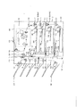
図1は本発明の実施形態に係る画像形成装置及びオプション装置からなる画像形成システムの構成例を示す図である。本実施形態において、画像形成装置は、電子写真プロセスによってシート上にトナー画像を形成するものである。
【0015】
同図において100は画像形成装置、101、102は給紙オプション装置、133、134は排紙オプション装置を表している。画像形成装置100はオプション装置101の上部に配置され、オプション装置101はオプション装置102の上部に配置されている。
【0016】
104〜107は画像形成装置で画像が転写されるシートであり、複数枚積載されている。また、シート104及び105は画像形成装置が内蔵する給紙装置に置かれている。108〜111はシートを送り出すピックアップローラであり、112〜120までのローラ群でシートを電子写真プロセス部103に搬送する。
【0017】
ローラ対117は画像形成装置100内で搬送されるシートとオプション装置101から搬送されるシートが合流する位置よりシート搬送路の下流に設置されている。画像形成装置100内で先行するシートの搬送が行われていた場合、オプション装置101からのシートをローラ対117の手前の位置で一時的に停止させる。
【0018】
ローラ対119はオプション装置101内で搬送されるシートとオプション装置102から搬送されるシートが合流する位置より下流に設置されている。オプション装置101内で先行するシートの搬送が行われていた場合、オプション装置102からのシートをローラ対119の手前の位置で一時的に停止させる。
【0019】
121は画像形成装置100とオプション装置101間を通信可能に接続する際のコネクタを示しており、画像形成装置100内のコントローラ127とオプション装置101内のコントローラ128とオプション装置102内のコントローラ129の通信を行う際に用いる通信線130aおよび電源制御信号線130bを中継している。また、121と同様に122はオプション装置101とオプション装置102間を接続しているコネクタを示しており通信線130cおよび電源制御信号線130dを中継している。
【0020】
123は画像形成装置内の電子写真プロセス部103で画像形成されたシートを積載するトレイであり、画像形成されている面が下になるようにローラ対124で搬送される。
【0021】
125は画像形成装置内の電子写真プロセス部103で画像形成されたシートの排出口であり、画像形成されている面が上になるようにローラ対126で搬送される。
【0022】
複数枚積載されているシート104〜107は、図1中の点線と矢印で示された搬送路をローラ群によって搬送され、表面に画像形成されて123トレイ上もしくは、排出口125に排出される。
【0023】
131は画像形成装置100内のシート搬送路の合流点(1)を示しており、ローラ対117の手前(上流側)に位置する。合流点(1)131は、画像形成装置100内で搬送するシート105とオプション装置101から搬送されるシート106の搬送路が合流する位置を示している。
【0024】
132はオプション装置101内のシート搬送路の合流点(2)を示しており、ローラ対119の手前に位置する。合流点(2)132は、オプション装置101内で搬送するシート106とオプション装置102から搬送されるシート107の搬送路が合流する位置を示している。
【0025】
133は画像形成装置100の下流に接続されているオプション装置であり、画像形成装置から排出されたシートを、オプション装置133に設けられたトレイに排出したり、下流のオプション装置134へ排出する。
【0026】
134はオプション装置133の下部に設置されたオプション装置であり、オプション装置133から搬送されたシートを搬送し、排出する装置である。
【0027】
135および136は、オプション装置133、134で搬送されたシートを積載するトレイであり、137〜142は画像形成装置100から排出されたシートを搬送するためのローラ対である。図1においては、説明を簡単にするため、トレイ135及び136にシートを搬出するためのローラ対138及び142のみが記載されているが、実際には他のトレイにシートを搬出するためのローラ対も同様に設けられている。
【0028】
143、144は、オプション装置133、134のコントローラであり、信号線145cおよび電源制御信号線145dで接続されている。また、信号線145aおよび電源制御信号線145bは、画像形成装置100内のコントローラ127と、コントローラ143を接続している。149、150は画像形成装置100、オプション装置133の間と、オプション装置133、134間に設置されているコネクタであり、信号線145a、145cおよび電源制御信号線145b、145dを中継している。
【0029】
ただし、コネクタ121、122、149、150は、搬送路順に接続可能なケーブルもしくは他の通信手段に置きかえても構わない。
【0030】
(コントローラの構成)
図2は画像形成装置100内のコントローラ127、オプション装置101内のコントローラ128、オプション装置102内のコントローラ129の構成及び接続関係を示したブロック図である。ただし、オプション装置133、134内のコントローラ143、144に関しては、コントローラ128、129と同様の構成であるため不図示である。
【0031】
200はコントローラ127内にあり、画像形成装置を制御し画像形成およびシート搬送を制御するCPUを示したものであり、CPU200の内部にはROM200a、RAM200b、タイマー200cが内蔵されている。ただし、ROM200a、RAM200b、タイマー200cはCPU200の外部に設置されていても構わない。
【0032】
ROM200aは、CPU200で実行すべき処理内容を常時保持しており、画像形成処理およびシート搬送処理および通信処理についてのソフトウェアが書き込まれている。
RAM200bは、CPU200で画像形成処理、シート搬送処理、通信処理を実行する際に一時的に必要なデータを保持する。
タイマー200cは、画像形成処理、シート搬送処理、通信処理を行う際に、各種タイミングを生成する。
【0033】
201は画像形成回路であり、画像形成装置でシート上に画像を形成する際の電子写真プロセスを行うための回路である。
202は画像形成装置でのシート搬送および画像形成処理を行う際に駆動する各種アクチュエータ(不図示)を制御するための回路である。
【0034】
203は画像形成装置でのシート搬送および画像形成処理を行う際に各種センサ(不図示)からの出力信号をCPU200に入力するための回路である。
204は画像形成装置からオプション装置への電源を投入/切断する処理を行うための回路であり、電源制御信号線130bを介してオプション装置101の電源回路を制御する。
【0035】
206は画像形成装置とオプション装置間の通信処理を行うための回路であり、通信線130dを介してオプション装置に接続されている。ただし、接続形態は特に限定されるものではない。
【0036】
207、214はそれぞれコントローラ128、129内にあり、オプション装置101、102を制御し画像形成装置100へのシート搬送を制御するCPUを示したものであり、CPU207、214の内部にはROM207a,214a、RAM207b,214b、タイマー207c,214cが内蔵されている。ただし、ROM207a,214a、RAM207b,214b、タイマー207c,214cはCPU207、214の外部に設置されていても構わないものとする。
【0037】
ROM207a,214aは、CPU207、214で実行すべき処理内容を常時保持しており、シート搬送処理および通信処理についてのソフトウェアが書き込まれているものである。
RAM207b,214bは、CPU207、214でシート搬送処理、通信処理を実行する際に一時的に必要なデータを保持するものである。
【0038】
タイマー207c,214cは、シート搬送処理、通信処理を行う際に、各種タイミングを生成するためのものである。
212、218はオプション装置101、102内でのシート搬送を行う際に駆動する各種アクチュエータ(不図示)を制御するための回路である。
【0039】
213、219はオプション装置101、102内でのシート搬送処理を行う際に各種センサ(不図示)からの出力信号をCPU207、214に入力するための回路である。
209、216はオプション装置から他のオプション装置の電源を投入/切断する処理を行うための回路であり、209は電源制御信号線130dを介してオプション装置の電源回路を制御する。
【0040】
211、217は画像形成装置100とオプション装置101、102間の通信処理を行うための回路であり、通信線130cを介してオプション装置に接続されている。ただし、接続形態は特に限定されるものではない。
【0041】
(電源投入時の動作)
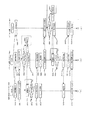
図3(a)〜(c)は、画像形成装置100、オプション装置101、102、133及び134の電源投入後の処理手順を示したフローチャートである。図3(a)が画像形成装置100の動作を、図3(b)がオプション装置101及び133の動作を、また図3(c)がオプション装置102及び134の動作をそれぞれ示している。
【0042】
ステップS100では画像形成装置100の電源が投入された直後にCPU200の初期化を行う。次のステップS101で接続されているオプション装置101の電源を投入するまでの時間を計測するタイマー200cを起動する。これは、同時に全ての装置の電源を一度に投入することによる周辺のACライン(不図示)の電圧変動を防止するために、起動時間差を設けるためと、画像形成装置100に近いオプション装置から順に上流もしくは下流に接続されているオプション装置を1台ずつ認識するためである。
【0043】
ステップS102では、ステップS101で起動したタイマー200cによって所定時間経過したかを確認し、経過していれば次のステップS103でオプション装置101の電源投入を行うための信号を出力する。
【0044】
一方、オプション装置101は、ステップS200(図3(b))で、オプション装置101に対して出力された信号によって電源を起動し、ステップS201でオプション装置101内のCPU207の初期化処理を行う。
【0045】
ステップS202では、オプション装置101のさらに上流に接続されているオプション装置102の電源を投入するための207cタイマーを起動する。
【0046】
ステップS203では、ステップS200で起動した207cタイマーによって所定時間経過したかを確認し、経過していればステップS204で更に上流のオプション装置102の電源投入を行うための信号を出力する。
【0047】
ステップS205では、オプション装置101が電源を投入されてから所定時間後に通信処理で、画像形成装置100へオプション装置101の情報を送信する。この送信内容はオプション装置101の機能や状態に関する情報である。
【0048】
ステップS205で送信されたデータは画像形成装置100で受信され(ステップS104)、ステップS105において画像形成装置100はシート搬送路上の1つ上流に100オプション装置が接続されていることを認識しオプション装置101との接続状態をRAM200b上に設定する。
【0049】
一方、オプション装置102では、オプション装置101がステップS204で出力した電源投入信号をステップS300(図3(c))で受信し、オプション装置102の電源を起動した後、ステップS301でオプション装置102内のCPU214の初期化処理を行う。
【0050】
ステップS303ではさらに上流に接続されているオプション装置の電源を投入するための処理を行う。本実施形態ではオプション装置102のさらに上流に他のオプション装置は接続されていないが、オプション装置102の上流にさらに給紙オプション装置が接続されている3台以上の構成においても、同様の電源投入信号の出力は行うものとする。
【0051】
次にステップS305では、下流のオプション装置101へオプション装置102の情報を送信する。ステップS206(図3(b))でオプション装置102の情報を受信したオプション装置101は、ステップS207でオプション装置101の1つ上流にオプション装置102が接続されていることを認識しオプション装置102との接続状態をRAM207b上に設定するとともに、オプション装置102の装置情報を画像形成装置100に転送する。
ステップS305においては、オプション装置102が直接画像形成装置100に自らの情報を送信するように構成することもできる。
【0052】
画像形成装置100は、ステップS107においてシート搬送路での2つ上流にオプション装置102が接続されていることを認識しオプション装置102との接続状態をRAM200b上に設定する。
また、オプション装置102の上流にさらに複数の給紙オプション装置が接続されている3台以上の構成においても、順次装置情報を下流のオプション装置に送信し、受信した下流のオプション装置は上流に接続されている装置情報を保持するものとする。さらに画像形成装置100は上流の給紙オプション装置全ての装置情報と接続状態をRAM200b上に設定する。
【0053】
ただし、オプション装置101、102間の接続状態の設定を行う際の処理として、オプション装置102はオプション装置101に対して自装置情報を送信することなく、画像形成装置100のみに送信し、画像形成装置100がオプション装置101にオプション装置102の情報を送信するようにしても良い。
【0054】
図3で示したフローチャートに従えば、画像形成装置100は1つ上流に設置れているオプション装置101の電源を投入することができ、オプション装置101は1つ上流に設置されているオプション装置102の電源を投入することができる。また、画像形成装置100は上流のオプション装置101、102の情報と接続状態を認識することができ、オプション装置101は1つ上流のオプション装置102の情報と接続状態を認識することができる。
【0055】
本実施形態において画像形成装置100の下流に接続されたオプション装置133、134に関しては、電源投入の順序が上流から下流へと変わる他は、オプション装置101、102と同様の動作を行なう。すなわち、画像形成装置100から上流側へ順次電源投入を行い順次オプション装置情報を受信する処理を、下流側へ順次電源投入を行い、順次オプション装置情報を受信する処理に置きかえることで、全てのオプション装置の電源投入と、情報および接続状態を認識することができる。
さらに、給紙オプション装置101,102や、排紙オプション装置133,134の他に複数のオプション装置が上流もしくは下流に接続された構成においても、同様である。
【0056】
この際、画像形成装置100から見て上流側に接続された全てのオプション装置を先に認識してから下流側のオプション装置を認識するか、その逆にするかは任意である。また、画像形成装置100が、上流側のオプション装置からの装置情報と、下流側のオプション装置からの装置情報とを独立して受信可能であれば、並行して電源投入を行なっても良い。
【0057】
(シート搬送(供給)処理)
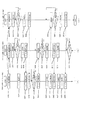
図4(a)〜(d)および図5(a)〜(c)は画像形成装置100、オプション装置101及び102、102より上流のオプション装置(図1では不図示)でのシート搬送処理を示すフローチャートである。
【0058】
図4(a)及び図5(a)は画像形成装置100の動作を、図4(b)及び図5(b)はオプション装置101の動作を、図4(c)及び図5(c)はオプション装置102の装置の動作を、図4(d)は102より上流のオプション装置の動作をそれぞれ示している。
【0059】
以下、シート1(図1、シート106)をオプション装置101から供給し、シート2(同シート107)をオプション装置102からオプション装置101を経由して画像形成装置100に供給し、シート3(不図示)をオプション装置102より上流のオプション装置から供給してオプション装置102及びオプション装置101を経由して画像形成装置100に供給するケースを例にして動作を説明する。
【0060】
まず、ステップS400で、画像形成装置100は、シート搬送情報をオプション装置101、102、及び102より上流のオプション装置に送信する。
シート搬送情報は、オプション装置101、102、及び102より上流のオプション装置のいずれかを指定してシートの供給を指示するとともに、その下流オプション装置にそのシートの搬送を指示するものである。複数のシートの供給が指示された場合、指示された順に画像形成装置100に供給されるように各シートの搬送が制御される。
【0061】
オプション装置101は、ステップS500で画像形成装置100よりシート1、2、3の搬送情報を受信し認識する。また、RAM207bに受信したシート1およびシート2、3の搬送情報を保存する。オプション装置101はオプション装置102からのシート2を搬送するため、シート2の搬送情報を受信するものとする。また、オプション装置101は102より上流のオプション装置からのシート3をも搬送するため、シート3の搬送情報を受信するものとする。次いで、シート1の搬送を開始する(ステップS501)。また、タイマー207cを起動する。以下、各装置内のタイマーは、各シートを搬送する際にシートの搬送タイミングを判断するため設定し、搬送制御に用いるものとする。
【0062】
一方、オプション装置102では、ステップS600で画像形成装置100よりシート2の搬送情報を受信し認識し、オプション装置102は102より上流のオプション装置からのシート3を搬送するため、シート3の搬送情報をも受信する。また、RAM214bに受信したシート2およびシート3の搬送情報を保存する。そして、シート2の搬送を開始する(ステップS601)。また、タイマー214cを起動する。
【0063】
ステップS501でオプション装置101がシート1の搬送を開始すると、画像形成装置100は、シート1が画像形成装置100内に搬送された際に、センサ入力回路203からの信号で、シート1の搬送を確認し搬送制御を開始する(ステップS401)。また、画像形成装置100はセンサ信号を検知せずにシート1を搬送するために、あらかじめローラ対118の駆動動作を行っていてもよい。
【0064】
オプション装置101はステップS502でシート1がローラ対117の手前の合流点(1)131に到達したかどうかをタイマー207cで判断し、到達していればステップS503で、シート1の搬送を停止する。ただし、合流点(1)131に他のシートが存在しなければシート1の搬送を停止せず継続しても構わない。
【0065】
次にステップS504でオプション装置101はシート1の搬送停止を画像形成装置100に通知するためのデータを送信し、ステップS402で画像形成装置100はシート1が搬送を停止したことを示すデータを受信し認識する。また、画像形成装置100内でのシート1の搬送を停止する。
【0066】
ステップS601でシート2の搬送を開始したオプション装置102では、ステップS602でシート2がローラ対119の手前の合流点(2)132に到達したかどうかをタイマー214cで判断し、到達していればステップS603でシート2の搬送を停止する。ただし、合流点(2)132に他のシートが存在しなければシート2の搬送を停止せず継続しても構わない。
【0067】
次にオプション装置102は、ステップS604でシート2の搬送停止を通知するためのデータをオプション装置101に送信する。このデータはオプション装置101で受信され(ステップS505)、オプション装置101はシート2の搬送が停止したことを認識する。
【0068】
画像形成装置100は、ステップS403で、シート1が画像形成装置100内の合流点(1)131を通過可能か判断し、通過可能であればステップS404に進みオプション装置101に対してシート1が搬送可能であること示すデータを送信する。
【0069】
ステップS506及びステップS507でオプション装置101は通信データを監視しており、ステップS404で画像形成装置100が出力したデータが、シート1が合流点(1)131を通過可能であることを示すデータであると判断した際にステップS508に進む。
【0070】
ステップS508ではオプション装置101内のシート1の搬送処理を再開し、また、ステップS405では画像形成装置100内のシート1の搬送を再開する。
【0071】
オプション装置101は、ローラ対119の手前の合流点(2)132をシート2が通過可能になった時点でオプション装置102に通過可能を示すデータを送信する(ステップS509)。オプション装置102では、ステップS603で搬送停止していたシート2が、合流点(2)132を通過可能になったかの検出のために通信を監視し(ステップS606、S607)、オプション装置101から合流点(2)132の通過が可能である旨のデータを受信したことを判断した後、ステップS608でシート2の搬送を再開する。
【0072】
オプション装置101からシート1が排出されると、画像形成装置100へシート1の排出完了データを送信し(ステップS510)、画像形成装置100はステップS406でシート1排出完了データを受信し認識する。
そして、画像形成装置100はステップS407で画像形成装置100内に搬送されたシート1に対して画像形成処理を行う。
【0073】
一方、シート1を排出完了したオプション装置101は、オプション装置102からオプション装置101に搬送されたシート2の搬送を開始する(ステップS511)。
【0074】
オプション装置102は、シート2を排出し終わるとステップS610でシート2の排出完了を示すデータをオプション装置101に送信し、オプション装置101はシート2排出完了を示すデータをステップS512で受信する。
【0075】
画像形成装置100はステップS408で、画像形成装置100にシート2が搬送されたことをセンサ入力回路203からの信号で検知すると、シート2の搬送を開始する。また、画像形成装置100はセンサ信号を検知せずにシート2を搬送するために、あらかじめローラ対118の駆動動作を行っていてもよい。
【0076】
オプション装置101はステップS513でシート2がローラ対117の手前の合流点(1)131に到達したかどうかを判断し、到達していればステップS514(図5(b))でシート2の搬送を停止する。ただし、合流点(1)131に他のシートが存在しなければシート2の搬送を停止せず継続しても構わない。
【0077】
ステップS515でオプション装置101はシート2の搬送停止を画像形成装置100に通知するためのデータを送信し、画像形成装置100はシート2が搬送を停止したことを示すこのデータを受信し認識する。そして、画像形成装置100内におけるシート2の搬送を停止する(ステップS409)。
【0078】
ステップS410では、シート2が画像形成装置100内の合流点(1)131を通過可能か判断し、通過可能であればステップS411に進みオプション装置101に対してシート2が搬送可能であることを示すデータを送信する。
ステップS517でオプション装置101は通信データを監視しており、ステップS518でシート2が合流点(1)131を通過可能であると判断した際にステップS519に進む。
【0079】
ステップS519ではオプション装置101内のシート2の搬送処理を再開する。また、画像処理装置100もステップS412でシート2の搬送処理を再開する。
ステップS521でオプション装置101からシート2が排出された際にシート2の排出完了を示すデータを通信処理で画像形成装置100へ送信する。
【0080】
このデータをステップS413で受信した画像形成装置100は、ステップS414でシート2に対する画像形成処理を行う。
以上、シート1、2についての搬送制御について説明してきたが、シート3についてもシート2と同様、102より上流のオプション装置から一つ下流のオプション装置102へ、さらに下流のオプション装置101へ、そして画像形成装置100へと、ステップS620〜ステップS628で示すように順次搬送していく。最終的には、ステップS419、S529、S619までのステップにおいて、シート1〜3の順に画像形成装置100に搬送し、画像形成を行う。
【0081】
図4および図5のフローチャートに示したシート搬送、監視処理に従えば、画像形成装置100は接続されている全てのオプション装置101、102および102より上流のオプション装置に対してシート搬送情報を最初に送信し、シート搬送処理が開始されてから1つ上流のオプション装置101のみのシートの搬送制御および監視を行い、オプション装置101は1つ上流のオプション装置102のみのシートの搬送制御および監視を行い、オプション装置102は1つ上流のオプション装置のみのシートの搬送制御および監視を行うことで、全てのシートに対して画像形成処理および搬送処理を行うことができる。
また、さらに複数の給紙オプション装置が上流に接続された構成においても、各装置が一つ上流の給紙オプション装置のシート搬送制御および監視を行うことで、全てのシートに対して画像形成処理および搬送処理を行うことができる。
【0082】
(シート搬送(排出)処理)
図6(a)〜(c)および図7(a)〜(c)は画像形成装置100、オプション装置133及び134でのシート搬送処理を示すフローチャートである。
図6(a)及び図7(a)は画像形成装置100の動作を、図6(b)及び図7(b)はオプション装置133の動作を、図6(c)及び図7(c)はオプション装置134の装置の動作をそれぞれ示している。
【0083】
以下、シート1、2を画像形成装置100からオプション装置133を経由してオプション装置134に搬送、排出、積載するケースを例にしてシートの搬送、排出処理を説明する。
まず、ステップS700で、画像形成装置100からシート搬送情報をオプション装置133、134に送信する。シート搬送情報は、積載されるべきオプション装置を指定してシートの排出・積載を指示するとともに、その上流側オプション装置にシートの搬送を指示するものである。
シート搬送情報は、ステップS800及びステップS900でオプション装置133及び134に受信される。
【0084】
ステップS701では、画像形成装置100のすぐ下流に接続されているオプション装置133へシート1の排出が可能かどうかを問い合わせるデータを送信する。オプション装置133はステップS801でこの問い合せをデータを受信し、ステップS802でシート1が搬送可能か判断する。シート1の搬送が不可能な状態であった場合、オプション装置133はステップS803でその旨を画像形成装置100へ通知し、また、シート1が搬送可能であると判断された場合には、ステップS804でその旨を画像形成装置100へ通知する。これらの通知はどちらの場合も通信監視中(ステップS702)の画像形成装置100に受信される。
【0085】
画像形成装置100はステップS702で受信した通知をもとに、シート1が画像形成装置100の排出口125を通過可能かステップS703で判断し、通過可能であればステップS704に進む。一方、通過不可能であれば、オプション装置133よりシート搬送が可能であることを通知されるまでステップS702で通信監視処理を行う。
【0086】
ステップS704では、画像形成装置100からシート1が排出される予告をオプション装置133に対して行い、その後ステップS705ではシート1の排出を開始する。オプション装置133はステップS805でシート1の排出予告を受信したのち、ステップS806でシート1の搬送を開始する。
【0087】
次に、オプション装置133は、ステップS807でオプション装置133内を搬送されているシート1の排出が可能であるかどうかを、下流に位置するオプション装置134へ問い合せる。
【0088】
この問い合わせデータは、ステップS901でオプション装置134が受信し、ステップS902でシート1の搬送が可能かどうかの判断を行う。シート1の搬送が不可能であった場合、ステップS903でオプション装置133へ通知する。また、シート1の搬送が可能であった場合には、ステップS904で搬送可能であることを通知する。
【0089】
オプション装置133では、ステップS808で通信を監視し、オプション装置134から受信した通知に基づきステップS809でシート1の排出が可能であるかどうかを判断する。シート1の排出が可能であれば次のステップS810にすすみ、画像形成装置100にシート1の排出開始と、通知を行う。また、続くステップS811では、オプション装置133からシート1を排出する前に排出予告をオプション装置134へ通知する。
【0090】
オプション装置134は、ステップS905でオプション装置133からの排出予告を受信すると、オプション装置134へ搬送されたシート1の搬送を開始する(ステップS906)。
【0091】
画像形成装置100は、例えばシート1の排出が終了すると、シート2の排出が可能であるかどうかの問い合せをオプション装置133へ行う(ステップS707)。
【0092】
オプション装置133はこの問い合わせをステップS812で受信し、ステップS813で、オプション装置133でシート2が搬送可能かどうかの判断を行う。シート1の処理中等の理由でシート2の搬送が不可能であった場合、その旨をステップS814で画像形成装置100へ通知する。また、搬送が可能な場合は、ステップS815で搬送可能であることを画像形成装置100へ通知する。
このオプション装置133の判断結果はステップS708で画像形成装置100に受信され、画像形成装置100は受信した判断結果に基づいてシート2が排出口125を通過可能かを判断する(ステップS709)。通過不可能であると判断された場合には、通過可能と判断されるまで待つ。一方、通過可能であることをオプション装置133より通知されていれば、ステップS710でシート排出予告をオプション装置133へ通知する。この通知はステップS816でオプション装置133に受信され、オプション装置133は、シート2の排出予告を認識する。
【0093】
画像形成装置100はシート2の排出予告に続き、ステップS711でシート2の排出を開始し、またオプション装置133もステップS817でシート2の搬送を開始する。
【0094】
ステップS818では、オプション装置133におけるシート1の排出完了を画像形成装置100へ通知し、ステップS712で画像形成装置100が受信し、認識する。次いでオプション装置133は、ステップS819でシート2の排出が可能かどうかをオプション装置134へ問い合せる。
【0095】
この問い合わせはオプション装置134がステップS907で受信し、ステップS908では、オプション装置134でシート2の搬送が可能かどうかを判断する。搬送が不可能であった場合はステップS909で、搬送が可能であると判断された場合にはステップS910で、それぞれ判断結果をオプション装置133へ通知する。
【0096】
オプション装置133はオプション装置134でのシート2搬送可否結果を、ステップS820で受信する。そして、ステップS821で、シート2の排出が可能であることをオプション装置134から通知されているかどうかの判断を行い、その旨の通知があるまで待つ。
【0097】
オプション装置134では、先行しているシート1がオプション装置134より排出されたら、その旨をオプション装置133へ通知する(ステップS911)。オプション装置133は、ステップS822でオプション装置134におけるシート1の搬送完了を受信すると、ステップS823でオプション装置134よりシート1が排出されたことを画像形成装置100へ通知するとともに、ステップS824では、シート2の排出予告をオプション装置134へ通知する。
【0098】
オプション装置134は、オプション装置133からのシート2排出予告をステップS912で受信し、認識する。そして、ステップS913では、ステップS912で受信した排出予告に基づき、シート2の搬送を開始する。
【0099】
一方、オプション装置133は、ステップS824で出力した排出予告に引き続き、ステップS825でシート2の排出を開始する。シート2のオプション装置133内における搬送が終了すると、ステップS826でその旨を画像形成装置100へ通知する。画像形成装置100はこの通知をステップS714で受信し、認識する。
【0100】
シート2の排出が完了すると、オプション装置134は、ステップS914では、その旨をオプション装置133へ通知して処理を終了する。オプション装置133はステップS827でオプション装置134でのシート2排出完了を受信すると、ステップS828でオプション装置134よりシート2が排出されたことを画像形成装置100へ通知する。そして、画像形成装置100がステップS715でオプション装置134でのシート2排出完了を受信、認識して、一連の排出処理は終了する。
【0101】
図6および図7のフローチャートに示したシート搬送制御および監視処理に従えば、画像形成装置100は接続されている全てのオプション装置133、134に対してシート搬送情報を最初に送信し、シート搬送処理が開始されてから1つ下流のオプション装置133のみのシートの搬送制御および監視を行い、オプション装置133は1つ下流のオプション装置134のみのシートの搬送制御および監視を行うことで、全てのシートに対して画像形成処理および搬送処理を行うことができる。
また、排紙オプション装置133,134の他に複数の排紙オプション装置が下流に接続された構成においても、各装置が一つ下流の排紙オプション装置のシート搬送制御および監視を行うことで、画像形成された全てのシートに対して搬送処理を行うことができる。
【0102】
(第2の実施形態)
次に、本発明の第2の実施形態にかかる画像形成装置及びオプション装置のシート搬送処理動作について、図8及び図9に示すフローチャートを用いて説明する。 図8(a)〜(c)および図9(a)〜(c)は画像形成装置100、オプション装置133及び134でのシート搬送処理を示すフローチャートである。そして、図8(a)及び図9(a)は画像形成装置100の動作を、図8(b)及び図9(b)はオプション装置133の動作を、図8(c)及び図9(c)はオプション装置134の装置の動作をそれぞれ示している。
【0103】
本実施形態において、画像形成装置の構成自体は図1に示した第1の実施形態のものと同一であるため、その説明は省略する。また、以下に説明するシート搬送処理においては、第1の実施形態と同様に、シート1及びシート2がオプション装置133を経由してオプション装置134から排出されるものとする。
【0104】
まず、ステップS716で、画像形成装置100からシート1及び2の搬送情報を133,オプション装置134へ送信する。この搬送情報はそれぞれステップS829,ステップS915でオプション装置133及び134に受信される。オプション装置133及び134は、搬送情報を受信すると、ステップS830,ステップS916にて自装置でシート1および2の搬送が可能になるまでの時間を上流に接続されている装置へ送信する。
【0105】
オプション装置133では、ステップS831でオプション装置134よりシート1、2搬送待ち時間データを受信し、ステップS832にてオプション装置133の待ち時間と合わせて画像形成装置100に送信する。
【0106】
画像形成装置100では、ステップS717でオプション装置133のシート1、2搬送待ち時間を受信し、ステップS718でオプション装置134の待ち時間を受信する。
【0107】
ステップS719では、シート1が排出口125を通過できるかの判断を行う。この判断は、ステップS717で受信したシート1および2の搬送待ち時間を基に、画像形成装置100内のタイマー200cで搬送待ち時間に相当するカウントを行なった後に215排出口を通過可能であるとする。
【0108】
ここで、搬送待ち時間の算出方法について説明する。あるシート(先行シートとする)が搬送され、オプション装置133又は134に搬入されてから、オプション装置133又は134が次のシート(後続シートとする)を受け入れ可能になるまでの時間(先行シートの搬送や後処理に影響を与えず、また後続シートが先行シートに追いつかない時間)、即ち搬送待ち時間は、オプション装置内のシート排出口までの搬送距離、搬送するシートの長さ、搬送速度、後処理動作時間によって決定することができる。
【0109】
従って、これらの組み合わせにより決定される搬送待ち時間を、予めオプション装置内のROMなどの不揮発性記憶媒体に記憶し、参照するか、これらの値を用いて実時間で演算することによって搬送待ち時間を得ることが可能である。
【0110】
本実施形態においては、オプション装置133及び134が、シート搬送情報を受信すると、自らのシート搬送待ち時間を算出するものとして説明する。本実施形態のように、画像形成装置100に対して2つのオプション装置133及び134が接続されている場合、画像形成装置100における排出待ち時間には以下のように求めることが出来る。
【0111】
すなわち、オプション装置133が算出した搬送待ち時間をT1[S]、オプション装置134が算出した搬送待ち時間をT2[S]とすると、オプション装置134がオプション装置133を介して自らの搬送待ち時間T2[S]を画像形成装置100に送信する場合、オプション装置133は
T1>=T2の場合、画像形成装置100の搬送待ち時間はT1
T1<T2の場合、画像形成装置100の搬送待ち時間はT2
として画像形成装置100に搬送待ち時間を送信する。
【0112】
もちろん、図8とは異なり、各オプション装置133、134が個別に、かつ直接T1[S]及びT2[S]を画像形成装置100に送信し、上述の判断(計算)を画像形成装置100で行うように構成しても良い。
また、3台以上のオプション装置が接続されている場合には、同様に最も搬送待ち時間の長いオプション装置に合わせて画像形成装置100の搬送待ち時間を決定すればよい。
【0113】
各装置間での通信にかかる時間は、通常搬送待ち時間よりも十分に短いとし、上流の装置によって段階的に搬送待ち時間を算出する場合であってもオプション装置の数はこの搬送待ち時間の算出に要する時間に影響しない。ただし、演算能力の非常に低いオプション装置が混在している場合には、画像形成装置100がそのオプション装置を認識した時点で搬送待ち時間を直接画像形成装置100に送信するように構成することも可能である。
【0114】
搬送待ち時間が経過すると、画像形成装置100は、ステップS720でシート1の排出を開始するとともに、搬送予告をオプション装置133に送信する。
オプション装置133は、ステップS833において、画像形成装置100がステップS720で送信した搬送予告を受信すると、シート1の搬送を開始する。ステップS834でシート1が排出口近傍の所定位置に到達したか否かを図示しないセンサによりシートの先端位置を検出することによって検出し、シート1が所定位置に到達したことが検出されたらシート1の排出を開始する(ステップS835)。また、シート1の排出開始とともに、排出予告をオプション装置134へ送信する。
【0115】
オプション装置134は、ステップS917において、オプション装置133がステップS835で送信した排出予告を受信すると、シート1の搬送を開始する。
【0116】
オプション装置133は、シート1の排出が完了すると、その旨をステップS836で画像形成装置100に通知し、画像形成装置100はこの通知をステップS721で受信して、シート1がオプション装置133より排出されたことを認識する。そして、ステップS722で後続のシート2が排出口125を通過可能かどうかを判断する。この判断は、ステップS718で受信したシート2搬送待ち時間を基に、画像形成装置100内のタイマー200cでカウントした後に215排出口を通過可能であるとする。通過可能となったらステップS723でシート2の排出を開始するとともに、搬送予告をオプション装置133へ送信する。
【0117】
オプション装置133はステップS837において、画像形成装置100がステップS723で送信した搬送予告を受信すると、シート2の搬送を開始する。次いで、ステップS838でシート2が排出口近傍の所定位置に到達したか否かを図示しないセンサにより検出し、シート2が所定位置に到達したことが検出されたらシート2の排出を開始する(ステップS839)。また、シート2の排出開始とともに、排出予告をオプション装置134へ送信する。
【0118】
一方、オプション装置134においてもステップS918において、オプション装置133がステップS839で送信した排出予告を受信すると、シート2の搬送を開始する。また、ステップS919では、シート1がオプション装置134より排出された際に上流の装置であるオプション装置133へ通知する。
【0119】
オプション装置133はステップS840でオプション装置134におけるシート1の排出を受信し、ステップS841でシート1のオプション装置134からの排出を画像形成装置100へ通知する。画像形成装置100はステップS724で、オプション装置134からシート1が排出されたことを認識する。
【0120】
オプション装置133は次にステップS842でシート2がオプション装置133より排出されたことを画像形成装置100に通知し、画像形成装置100はステップS725でそれを認識する。
【0121】
オプション装置134は、シート2が最後に排出された際に、ステップS920でオプション装置133へ通知する。この通知はステップS843でオプション装置133で受信された後、ステップS844で画像形成装置100に伝達される。そして、画像形成装置100はステップS726でオプション装置134からシート2が排出完了したことを認識する。
【0122】
本実施形態で述べたように、画像形成装置は、下流に接続された複数のオプション装置から順にシートの排出が可能となるまでの時間を受信することと、画像形成装置の下流に接続された各々のオプション装置でシート搬送制御および監視処理を行うことで、処理負荷の軽減を実現できる。
また、排紙オプション装置133,134の他に複数の排紙オプション装置が下流に接続された構成においても、同様に処理負荷の軽減を実現できる。
【0123】
(第3の実施形態)
次に、本発明の第3の実施形態にかかる画像形成装置及びオプション装置のシート搬送動作について説明する。本実施形態は、第1の実施形態において図3のフローチャートを用いて説明したステップS104およびステップS106の処理において、オプション装置101、102から装置情報として、上流に接続されている他のオプション装置のシート搬送制御および監視処理が行えるかどうかを、通信データとして取得し、ステップS105,ステップS107で画像形成装置100は、オプション装置101、102の処理能力を判断し、オプション装置102の制御および監視ができないオプション装置101を介さずに、直接その上流のオプション装置102のシート搬送制御および監視処理を行うようにしたものである。
【0124】
また、不図示であるが、画像形成装置100の下流に接続されているオプション装置133,134に関しても同様に、画像形成装置100が直接、シート搬送制御および監視処理を行うものとする。
【0125】
その際の処理を図10に示すフローチャートを用いて説明する。図10は第1の実施形態において図4に示すフローチャートを用いて説明したシート搬送(供給)処理を変更したものであり、画像形成装置100がオプション装置101を、上流のオプション装置102のシート搬送制御および監視処理が出来ないと判断した後の処理を示す。なお、図10において、図4と同じ処理には同じステップ番号を付与し、その詳細な説明は省略する。
【0126】
ステップS409において、図4におけるステップS505に相当する処理が画像形成装置100で行われ、オプション装置102のシート搬送状態が直接画像形成装置100で把握される。同様に、図4におけるステップS509の処理がステップS411において画像形成装置100で行われ、オプション装置102に対して、シート1の状態を監視しながらシート2の搬送再開を指示する。
【0127】
さらに、ステップS413では、図4におけるステップS512に相当する処理、すなわちオプション装置102からシート2が排出されたことの認識が画像形成装置100でなされ、オプション装置101でシート2の搬送を引き続き行うことを認識する。
【0128】
この後、画像形成装置100がオプション装置101内のシート2の搬送制御および監視処理を行う。
【0129】
本実施形態では、シート供給オプション装置のみの処理についてのみ述べたが、画像形成装置100の下流に接続されているシート排出オプション装置に関しても、画像形成装置100が、処理能力の低いオプション装置を介さずに直接制御を行うことで、同様の処理を行うことができる。
【0130】
以上述べたように、本実施形態によれば、画像形成装置は、通信手段によって接続されている各オプション装置の処理能力を電源投入後に取得し、上流もしくは下流に接続されているオプション装置が他のオプション装置の制御および監視が行えないと判断した場合、そのオプション装置の1つ上流(又は下流)に接続されているオプション装置の制御を直接行うことができる。
【0131】
【他の実施形態】
上述した第1〜第3の実施形態では、画像形成装置100の上流に設置されているオプション装置は2台、下流に接続されているオプション装置も2台、シート搬送枚数を2枚としているが、この構成である必要はなく、接続されるオプションの台数、搬送されるシートの数及び画像形成処理や排出完了処理等のタイミングは、全て任意である。
【0132】
また、画像形成装置、オプション装置の間で行なわれる通信方法も特に限定されるものではなく、任意のプロトコルを用いることが可能である。
【0133】
さらに、上述の実施形態においては、シートの搬送に関わるオプション装置のみについて説明したが、シート搬送用のオプション装置以外であっても、画像形成装置から連続して接続されるようなオプション装置であれば本発明の効果は実現できる。
【0134】
また、図3においては、電源投入時にタイマーを起動し、タイマーのタイムアウトにより下流のオプション装置の電源投入を行うを行う場合を説明したが、例えば電源投入後に行われる初期化処理等の所定処理が終了した時点で下流のオプション装置の電源投入を行うように構成しても良い。
【0135】
なお、本発明は、複数の機器(例えばホストコンピュータ、インタフェイス機器、リーダ、プリンタなど)から構成されるシステムに適用しても、一つの機器からなる装置(例えば、複写機、ファクシミリ装置など)に適用してもよい。
【0136】
また、本発明の目的は、前述した実施形態の機能を実現するソフトウェアのプログラムコードを記録した記憶媒体(または記録媒体)を、システムあるいは装置に供給し、そのシステムあるいは装置のコンピュータ(またはCPUやMPU)が記憶媒体に格納されたプログラムコードを読み出し実行することによっても、達成されることは言うまでもない。この場合、記憶媒体から読み出されたプログラムコード自体が前述した実施形態の機能を実現することになり、そのプログラムコードを記憶した記憶媒体は本発明を構成することになる。また、コンピュータが読み出したプログラムコードを実行することにより、前述した実施形態の機能が実現されるだけでなく、そのプログラムコードの指示に基づき、コンピュータ上で稼働しているオペレーティングシステム(OS)などが実際の処理の一部または全部を行い、その処理によって前述した実施形態の機能が実現される場合も含まれることは言うまでもない。
【0137】
さらに、記憶媒体から読み出されたプログラムコードが、コンピュータに挿入された機能拡張カードやコンピュータに接続された機能拡張ユニットに備わるメモリに書込まれた後、そのプログラムコードの指示に基づき、その機能拡張カードや機能拡張ユニットに備わるCPUなどが実際の処理の一部または全部を行い、その処理によって前述した実施形態の機能が実現される場合も含まれることは言うまでもない。
【0138】
本発明を上記記憶媒体に適用する場合、その記憶媒体には、先に説明した(図3乃至図10のいずれか1つ以上に示す)フローチャートに対応するプログラムコードが格納されることになる。
【0139】
【発明の効果】
以上説明したように、本発明の画像形成装置及びオプション装置によれば、各装置が直下及び/又は直上のオプション装置の動作監視及び制御を行なうことにより、装置全体の管理を分散して行なうことが可能になり、画像処理装置もしくはオプションコントローラの処理負荷が低減されるほか、接続されるオプション装置の台数が変化しても画像処理装置における処理負荷が急激に増加することがないため、高速な処理が可能な高価な回路部品を用いることなく画像処理装置を構成することができるという効果を有する。
【図面の簡単な説明】
【図1】本発明の実施形態に係る画像形成装置とオプション装置の構成を表す図である。
【図2】本発明の実施形態に係る画像形成装置とオプション装置内コントローラの構成の概要を表すブロック図である。
【図3】本発明の実施形態に係る画像形成装置とオプション装置の電源投入および接続状態の設定処理手順を表すフローチャートである。
【図4】本発明の第1の実施形態に係る画像形成装置とオプション装置のシート搬送処理の手順を表すフローチャートである。
【図5】本発明の第1の実施形態に係る画像形成装置とオプション装置のシート搬送処理の手順を表すフローチャートである。
【図6】本発明の第1の実施形態に係る画像形成装置とオプション装置のシート搬送処理の手順を表すフローチャートである。
【図7】本発明の第1の実施形態に係る画像形成装置とオプション装置のシート搬送処理の手順を表すフローチャートである。
【図8】本発明の第2の実施形態に係る画像形成装置とオプション装置のシート搬送処理の手順を表すフローチャートである。
【図9】本発明の第2の実施形態に係る画像形成装置とオプション装置のシート搬送処理の手順を表すフローチャートである。
【図10】本発明の第3の実施形態に係る画像形成装置とオプション装置のシート搬送処理の手順を表すフローチャートである。
【符号の説明】
100 画像形成装置
101 オプション装置(シート供給)
102 オプション装置(シート供給)
103 電子写真プロセス部
104、105、106、107 シート
127 画像形成装置100内のコントローラ
128 オプション装置101内のコントローラ
129 オプション装置102内のコントローラ
133 オプション装置(シート排出)
134 オプション装置(シート排出)[0001]
BACKGROUND OF THE INVENTION
The present invention relates to an image forming apparatus to which a plurality of option devices can be connected and the option device.
[0002]
[Prior art]
2. Description of the Related Art Conventionally, various optional devices that can be connected to an image forming apparatus are prepared, and the functions of the image forming apparatus are expanded in accordance with the user's desire and usage environment.
Such optional devices include a paper feed option device for enabling a large amount of paper feed, a sorter, a duplex unit, and the like, each having a configuration capable of communicating with an image forming apparatus.
[0003]
For example, when a plurality of paper feed option devices are arranged and connected below the image forming apparatus, the image forming apparatus and the plurality of paper feed option devices communicate with each other from a desired paper feed option device to a recording medium such as paper. (Hereinafter referred to as a sheet) is conveyed to an image forming apparatus located downstream of the conveyance path.
[0004]
Conventionally, when connecting an image forming apparatus and a sheet feeding option apparatus for supplying a recording medium and performing medium conveyance control, a controller in the image forming apparatus monitors sheet conveyance control in all sheet feeding option apparatuses, If necessary, the control data is transmitted to the optional device to perform all sheet conveyance control and monitoring processing. Similarly, for a paper discharge option device that performs post-processing on a sheet discharged from the image forming apparatus, a controller in the image forming apparatus performs sheet conveyance control and monitoring processing of all the paper discharge option devices.
As another example, the sheet conveyance control and monitoring process of the optional apparatus for feeding and discharging paper is separated from the controller in the image forming apparatus, and all of the option controllers are integrated to control the sheet conveyance control and monitoring process of the optional apparatus. The optional apparatus is configured to perform sheet conveyance control and monitoring processing.
[0005]
[Problems to be solved by the invention]
However, such a conventional image forming apparatus has the following problems.
[0006]
If the number of sheet feeding option devices is one or the sheet conveyance speed is not fast, the sheet conveyance option device sheet conveyance control and monitoring processing may be performed by the controller or option controller in the image forming apparatus. , Thereby increasing the processing load on the controller is not a problem. However, when multiple optional devices are connected or the sheet conveyance speed is increased, the processing in the controller becomes complicated and high-speed processing is required, increasing the load of control and monitoring processing. In addition, it is necessary to use a high-speed and expensive processing device such as a CPU for the controller.
[0007]
SUMMARY OF THE INVENTION Accordingly, an object of the present invention is to provide an image forming apparatus, an image forming apparatus, an optional apparatus for the image forming apparatus, an image forming apparatus, and an optional apparatus for the image forming apparatus, which have a small increase in processing load even when a plurality of optional apparatuses are connected. An object of the present invention is to provide an image forming system including optional devices.
[0008]
[Means for Solving the Problems]
That is, the gist of the present invention is an image forming apparatus.Alternatively, the first connected to the image forming apparatusOptional equipmentEitherConnectableWhat, Image forming apparatusOr first optional deviceConnected to,MoreThe secondAn optional apparatus of an image forming apparatus to which an optional apparatus can be connected, the image forming apparatusOr firstOptional equipmentAnd a second optional deviceA communication means for performing communication and an image forming apparatus orFirstBased on instructions received from the optional device via communication meansOptional deviceOptional device control means for controlling the operation of the machineAnd having,The option device control means is configured to monitor the second option device from the second option device via the communication means in order to monitor the second option device in a state where the image forming apparatus or the first option device and the second option device are connected. Receives information indicating the status of optional devices,Information indicating the status of the received second optional deviceOn the basis of theOptional deviceThe image forming apparatus is an optional apparatus for controlling an image forming apparatus.
[0010]
Furthermore, another gist of the present invention is directed to an image forming apparatus and an image forming apparatus.Close contactCan continueOptional equipmentInWhatConnected to the image forming device,More,otherOptional devices that can be connected to other optional devicesWithAn image forming system, an optional deviceIs,First communication means for communicating with the image forming apparatus and other option apparatuses; and option device control means for controlling the operation of the option apparatus based on an instruction received from the image forming apparatus via the first communication means. The optional device control means is configured to monitor the other optional devices from the other optional devices via the first communication means in order to monitor other optional devices in a state where the image forming apparatus and the other optional devices are connected to the optional device. Receiving information indicating the status of the other optional device, controlling the operation of the optional device based on the received information on the status of the other optional device,
Image forming apparatusIs,Second communication means for communicating with option device control means of the option device;Image formation using optional equipmentActioncontrolDoImage forming control means having image forming control meansIs,To monitor the status of optional equipment,Image forming apparatusClose toContinued optional deviceInformation indicating the status of the optional device is received from the optional device control means via the second communication means, and the image forming operation is controlled based on the received information indicating the status of the optional device.It exists in the image forming system characterized by this.
[0014]
DETAILED DESCRIPTION OF THE INVENTION
(First embodiment)
(Configuration of image forming apparatus)
FIG. 1 is a diagram illustrating a configuration example of an image forming system including an image forming apparatus and an optional apparatus according to an embodiment of the present invention. In this embodiment, the image forming apparatus forms a toner image on a sheet by an electrophotographic process.
[0015]
In the figure, 100 is an image forming apparatus, 101 and 102 are paper feed option devices, and 133 and 134 are paper discharge option devices. The
[0016]
104 to 107 are sheets on which images are transferred by the image forming apparatus, and a plurality of sheets are stacked. The
[0017]
The
[0018]
The roller pair 119 is installed downstream from the position where the sheet conveyed in the option apparatus 101 and the sheet conveyed from the
[0019]
Reference numeral 121 denotes a connector for connecting the
[0020]
[0021]
125 is a discharge port for a sheet on which an image is formed by the
[0022]
A plurality of
[0023]
Reference numeral 131 denotes a merging point (1) of the sheet conveyance path in the
[0024]
Reference numeral 132 denotes a merging point (2) of the sheet conveyance path in the optional apparatus 101, which is located in front of the roller pair 119. A merge point (2) 132 indicates a position where the
[0025]
Reference numeral 133 denotes an optional device connected downstream of the
[0026]
An
[0027]
[0028]
[0029]
However, the
[0030]
(Configuration of controller)
FIG. 2 is a block diagram showing the configuration and connection relationship of the
[0031]
[0032]
The
The RAM 200b temporarily stores data necessary for the
The timer 200c generates various timings when performing image forming processing, sheet conveyance processing, and communication processing.
[0033]
An image forming circuit 201 is a circuit for performing an electrophotographic process when an image is formed on a sheet by the image forming apparatus.
[0034]
[0035]
[0036]
[0037]
The
The RAMs 207b and 214b hold data temporarily required when the
[0038]
The
[0039]
Reference numerals 213 and 219 denote circuits for inputting output signals from various sensors (not shown) to the
[0040]
[0041]
(Operation at power-on)
FIGS. 3A to 3C are flowcharts showing processing procedures after the
[0042]
In step S100, the
[0043]
In step S102, it is confirmed whether the predetermined time has elapsed by the timer 200c activated in step S101. If the predetermined time has elapsed, a signal for turning on the option device 101 is output in the next step S103.
[0044]
On the other hand, in step S200 (FIG. 3B), the option device 101 activates a power supply by a signal output to the option device 101, and performs initialization processing of the
[0045]
In step S202, a 207c timer for turning on the power of the
[0046]
In step S203, it is confirmed whether or not a predetermined time has elapsed by the 207c timer activated in step S200, and if it has elapsed, a signal for powering on the
[0047]
In step S <b> 205, information on the option device 101 is transmitted to the
[0048]
The data transmitted in step S205 is received by the image forming apparatus 100 (step S104). In step S105, the
[0049]
On the other hand, in the
[0050]
In step S303, processing for turning on the power of the optional device connected further upstream is performed. In this embodiment, no other option device is connected further upstream of the
[0051]
In step S305, information about the
In step S <b> 305, the
[0052]
In step S107, the
Also, in the configuration of three or more units in which a plurality of paper feed option devices are further connected upstream of the
[0053]
However, as a process for setting the connection state between the
[0054]
According to the flowchart shown in FIG. 3, the
[0055]
In the present embodiment, the
Further, the same applies to a configuration in which a plurality of option devices other than the paper
[0056]
At this time, it is optional to recognize all option devices connected to the upstream side as viewed from the
[0057]
(Sheet conveyance (supply) processing)
FIGS. 4A to 4D and FIGS. 5A to 5C show the sheet conveying process in the
[0058]
4A and 5A show the operation of the
[0059]
Hereinafter, the sheet 1 (FIG. 1, sheet 106) is supplied from the optional device 101, and the sheet 2 (same sheet 107) is supplied from the
[0060]
First, in step S <b> 400, the
In the sheet conveyance information, any of the
[0061]
In step S500, the option apparatus 101 receives and recognizes the conveyance information of the
[0062]
On the other hand, the
[0063]
When the option apparatus 101 starts conveying the
[0064]
In step S502, the option apparatus 101 determines whether or not the
[0065]
In step S504, the option apparatus 101 transmits data for notifying the
[0066]
In the
[0067]
Next, the
[0068]
In step S403, the
[0069]
In step S506 and step S507, the option apparatus 101 monitors the communication data, and the data output from the
[0070]
In step S508, the conveyance process of the
[0071]
The option device 101 transmits data indicating that the
[0072]
When the
Then, the
[0073]
On the other hand, the optional device 101 that has finished discharging the
[0074]
When the
[0075]
In step S <b> 408, when the
[0076]
In step S513, the option apparatus 101 determines whether or not the
[0077]
In step S515, the option apparatus 101 transmits data for notifying the
[0078]
In step S410, it is determined whether or not the
In step S517, the option apparatus 101 monitors the communication data, and when it is determined in step S518 that the
[0079]
In step S519, the conveyance process of the
When the
[0080]
The
The conveyance control for the
[0081]
According to the sheet conveyance and monitoring processing shown in the flowcharts of FIGS. 4 and 5, the
Further, even in a configuration in which a plurality of paper feed option devices are connected upstream, each device performs image transport processing and monitoring of the sheet feed option device of one upstream so that image formation processing is performed on all sheets. In addition, the conveyance process can be performed.
[0082]
(Sheet conveyance (discharge) processing)
FIGS. 6A to 6C and FIGS. 7A to 7C are flowcharts showing sheet conveyance processing in the
FIGS. 6A and 7A show the operation of the
[0083]
Hereinafter, sheet conveyance and ejection processing will be described by taking as an example a case in which the
First, in step S <b> 700, sheet conveyance information is transmitted from the
The sheet conveyance information is received by the
[0084]
In step S <b> 701, data for inquiring whether or not the
[0085]
Based on the notification received in step S702, the
[0086]
In step S704, a notice is given to the optional device 133 that the
[0087]
Next, in step S807, the option device 133 inquires of the
[0088]
The inquiry data is received by the
[0089]
The option device 133 monitors communication in step S808, and determines in step S809 whether the
[0090]
When the
[0091]
For example, when the discharge of the
[0092]
The option device 133 receives this inquiry in step S812, and in step S813, the option device 133 determines whether the
The determination result of the option device 133 is received by the
[0093]
Following the advance notice of discharging the
[0094]
In step S818, the
[0095]
This inquiry is received by the
[0096]
The option device 133 receives the result of whether or not the
[0097]
When the preceding
[0098]
The
[0099]
On the other hand, the option device 133 starts discharging the
[0100]
When the discharge of the
[0101]
According to the sheet conveyance control and monitoring processing shown in the flowcharts of FIGS. 6 and 7, the
Further, even in a configuration in which a plurality of paper discharge option devices are connected downstream in addition to the paper
[0102]
(Second Embodiment)
Next, the sheet conveyance processing operation of the image forming apparatus and the optional apparatus according to the second embodiment of the present invention will be described using the flowcharts shown in FIGS. FIGS. 8A to 8C and FIGS. 9A to 9C are flowcharts illustrating sheet conveyance processing in the
[0103]
In the present embodiment, the configuration of the image forming apparatus itself is the same as that of the first embodiment shown in FIG. Further, in the sheet conveyance processing described below, it is assumed that the
[0104]
First, in step S716, the conveyance information of the
[0105]
In step S831, the option device 133 receives the
[0106]
In step S717, the
[0107]
In step S719, it is determined whether the
[0108]
Here, a method for calculating the conveyance waiting time will be described. The time from when a certain sheet (referred to as the preceding sheet) is conveyed and carried into the
[0109]
Therefore, the transport waiting time determined by the combination of these is stored in advance in a non-volatile storage medium such as a ROM in the optional device and is referred to or calculated in real time using these values. It is possible to obtain
[0110]
In the present embodiment, it is assumed that the
[0111]
That is, assuming that the transport waiting time calculated by the option device 133 is T1 [S] and the transport waiting time calculated by the
When T1> = T2, the conveyance waiting time of the
When T1 <T2, the conveyance waiting time of the
As a result, the conveyance waiting time is transmitted to the
[0112]
Of course, unlike FIG. 8, each of the
If three or more optional devices are connected, the conveyance waiting time of the
[0113]
The time required for communication between each device is sufficiently shorter than the normal transport waiting time, and even if the transport waiting time is calculated step by step by an upstream device, the number of optional devices is equal to the transport waiting time. Does not affect the time required for calculation. However, in the case where optional devices with extremely low computing power are mixed, it may be configured such that the conveyance waiting time is directly transmitted to the
[0114]
When the conveyance waiting time elapses, the
In step S833, the option device 133 starts conveying the
[0115]
In step S917, the
[0116]
When the discharge of the
[0117]
In step S837, the option apparatus 133 starts conveyance of the
[0118]
On the other hand, also in the
[0119]
The option device 133 receives the discharge of the
[0120]
In step S842, the option apparatus 133 notifies the
[0121]
When the
[0122]
As described in the present embodiment, the image forming apparatus receives the time until the sheet can be discharged in order from a plurality of option apparatuses connected downstream, and is connected downstream of the image forming apparatus. By performing sheet conveyance control and monitoring processing with each optional device, the processing load can be reduced.
Further, in a configuration in which a plurality of paper discharge option devices are connected downstream in addition to the paper
[0123]
(Third embodiment)
Next, the sheet conveying operation of the image forming apparatus and the optional apparatus according to the third embodiment of the present invention will be described. In the present embodiment, in the processing of step S104 and step S106 described with reference to the flowchart of FIG. 3 in the first embodiment, as the device information from the
[0124]
Although not shown, the
[0125]
The processing at that time will be described with reference to the flowchart shown in FIG. FIG. 10 shows a modification of the sheet conveyance (supply) process described with reference to the flowchart shown in FIG. 4 in the first embodiment. The
[0126]
In step S409, processing corresponding to step S505 in FIG. 4 is performed by the
[0127]
Further, in step S413, the
[0128]
Thereafter, the
[0129]
In the present exemplary embodiment, only the processing of the sheet supply option device has been described, but the sheet discharge option device connected downstream of the
[0130]
As described above, according to the present embodiment, the image forming apparatus acquires the processing capability of each option device connected by the communication unit after the power is turned on, and the option device connected upstream or downstream is the other. If it is determined that the optional device cannot be controlled and monitored, it is possible to directly control the optional device connected one upstream (or downstream) of the optional device.
[0131]
[Other Embodiments]
In the first to third embodiments described above, two optional devices are installed upstream of the
[0132]
In addition, a communication method performed between the image forming apparatus and the optional apparatus is not particularly limited, and any protocol can be used.
[0133]
Further, in the above-described embodiment, only the optional device related to sheet conveyance has been described. However, an optional device that is continuously connected from the image forming apparatus can be used other than the optional device for sheet conveyance. The effect of the present invention can be realized.
[0134]
In FIG. 3, the case where the timer is started when the power is turned on and the downstream option device is turned on when the timer times out has been described. However, for example, a predetermined process such as an initialization process performed after the power is turned on is performed. It may be configured to power on the downstream option device when it is finished.
[0135]
Note that the present invention can be applied to a system including a plurality of devices (for example, a host computer, an interface device, a reader, and a printer), and a device (for example, a copying machine and a facsimile device) including a single device. You may apply to.
[0136]
Another object of the present invention is to supply a storage medium (or recording medium) in which a program code of software that realizes the functions of the above-described embodiments is recorded to a system or apparatus, and the computer (or CPU or CPU) of the system or apparatus. Needless to say, this can also be achieved by the MPU) reading and executing the program code stored in the storage medium. In this case, the program code itself read from the storage medium realizes the functions of the above-described embodiments, and the storage medium storing the program code constitutes the present invention. Further, by executing the program code read by the computer, not only the functions of the above-described embodiments are realized, but also an operating system (OS) running on the computer based on the instruction of the program code. It goes without saying that a case where the function of the above-described embodiment is realized by performing part or all of the actual processing and the processing is included.
[0137]
Furthermore, after the program code read from the storage medium is written into a memory provided in a function expansion card inserted into the computer or a function expansion unit connected to the computer, the function is determined based on the instruction of the program code. It goes without saying that the CPU or the like provided in the expansion card or the function expansion unit performs part or all of the actual processing and the functions of the above-described embodiments are realized by the processing.
[0138]
When the present invention is applied to the above-described storage medium, the storage medium stores program codes corresponding to the flowcharts described above (shown in any one or more of FIGS. 3 to 10).
[0139]
【The invention's effect】
As described above, according to the image forming apparatus and the optional apparatus of the present invention, each apparatus monitors and controls the operation of the optional apparatus directly below and / or directly above, thereby distributing the management of the entire apparatus. In addition to reducing the processing load on the image processing device or the optional controller, the processing load on the image processing device does not increase rapidly even if the number of connected optional devices changes. The image processing apparatus can be configured without using expensive circuit components that can be processed.
[Brief description of the drawings]
FIG. 1 is a diagram illustrating a configuration of an image forming apparatus and an optional apparatus according to an embodiment of the present invention.
FIG. 2 is a block diagram showing an outline of a configuration of an image forming apparatus and an optional device controller according to the embodiment of the present invention.
FIG. 3 is a flowchart illustrating a power-on and connection state setting processing procedure for an image forming apparatus and an optional apparatus according to an embodiment of the present invention.
FIG. 4 is a flowchart illustrating a sheet conveyance process procedure of the image forming apparatus and the optional apparatus according to the first exemplary embodiment of the present invention.
FIG. 5 is a flowchart illustrating a sheet conveyance process procedure of the image forming apparatus and the optional apparatus according to the first exemplary embodiment of the present invention.
FIG. 6 is a flowchart illustrating a sheet conveyance process procedure of the image forming apparatus and the optional apparatus according to the first exemplary embodiment of the present invention.
FIG. 7 is a flowchart illustrating a sheet conveyance process procedure of the image forming apparatus and the optional apparatus according to the first exemplary embodiment of the present invention.
FIG. 8 is a flowchart illustrating a procedure of sheet conveyance processing of an image forming apparatus and an optional apparatus according to a second embodiment of the present invention.
FIG. 9 is a flowchart illustrating a sheet conveyance process procedure of the image forming apparatus and the optional apparatus according to the second exemplary embodiment of the present invention.
FIG. 10 is a flowchart illustrating a sheet conveyance process procedure of an image forming apparatus and an optional apparatus according to a third embodiment of the present invention.
[Explanation of symbols]
100 Image forming apparatus
101 Optional equipment (sheet supply)
102 Optional equipment (sheet supply)
103 Electrophotographic process department
104, 105, 106, 107 sheets
127 Controller in
128 Controller in optional device 101
129 Controller in
133 Optional device (sheet discharge)
134 Optional device (sheet discharge)
Claims (8)
前記画像形成装置または前記第1オプション装置、及び、前記第2オプション装置と通信を行なう通信手段と、
前記画像形成装置もしくは前記第1オプション装置から、前記通信手段を介して受信した指示に基づいて前記オプション装置の動作を制御するオプション装置制御手段と、を有し、
前記オプション装置制御手段は、前記画像形成装置または前記第1オプション装置、及び、前記第2オプション装置が接続された状態において、前記第2オプション装置を監視するために、前記通信手段を介して前記第2オプション装置から前記第2オプション装置の状態を示す情報を受信し、受信した前記第2オプション装置の状態を示す情報に基づいて前記オプション装置の動作を制御することを特徴とする画像形成装置のオプション装置。 What connectable der to any one of the first option device connected to the image forming apparatus or the image forming apparatus, the connected state to the image forming apparatus or the first option device, further, a second optional apparatus Is an optional device of the image forming apparatus that can be connected,
Before Symbol image forming apparatus or the first option device, and a communication unit communicating with the second option device,
From the image forming apparatus or the first option device has, and the option device control means for controlling the operation of the option device based on an instruction received via said communication means,
The optional device control means is configured to monitor the second optional device via the communication means in a state where the image forming apparatus or the first optional device and the second optional device are connected. An image forming apparatus that receives information indicating a state of the second option device from a second option device and controls an operation of the option device based on the received information indicating a state of the second option device. Optional equipment.
前記電源制御手段は、前記オプション装置の電源が投入されてから所定時間後に前記前記第2オプション装置の電源を投入するよう指示することを特徴とする請求項1記載の画像形成装置のオプション装置。Further comprising a power control means for performing power-on control for the previous SL second option device,
Said power supply control means, optional Claim 1 image forming apparatus, wherein the instructing the power supply of the option device to power before Symbol before Symbol second option device from being turned after a predetermined time apparatus.
前記オプション装置制御手段は、前記通信手段を介して前記第2オプション装置から、前記第2オプション装置におけるシートの搬送状態を示す情報を受信し、受信した前記情報に基づき前記オプション装置の動作を制御することを特徴とする請求項1又は2に記載の画像形成装置のオプション装置。 The option device control means receives information indicating the sheet conveyance state in the second option device from the second option device via the communication means, and controls the operation of the option device based on the received information. The optional apparatus for an image forming apparatus according to claim 1, wherein:
前記オプション装置制御手段は、前記通信手段を介して、前記第2オプション装置へのシートの排出が可能か否かを示す情報を前記第2オプション装置から受信し、受信した前記情報に基づいて前記オプション装置の動作を制御することを特徴とする請求項1または2に記載の画像形成装置のオプション装置。Before Kio option device, I sheet discharging option device der for processing sheets discharged from the image forming apparatus,
The option device control means receives information indicating whether or not the sheet can be discharged to the second option device via the communication means from the second option device, and based on the received information, 3. The optional apparatus for an image forming apparatus according to claim 1 , wherein operation of the optional apparatus is controlled .
前記オプション装置は、前記画像形成装置及び前記他のオプション装置と通信を行なう第1通信手段と、前記画像形成装置から、前記第1通信手段を介して受信した指示に基づいて前記オプション装置の動作を制御するオプション装置制御手段と、を有し、前記オプション装置制御手段は、前記オプション装置に前記画像形成装置と前記他のオプション装置が接続された状態において、前記他のオプション装置を監視するために、前記第1通信手段を介して、前記他のオプション装置から前記他のオプション装置の状態を示す情報を受信し、受信した前記他のオプション装置の状態に関する情報に基づいて前記オプション装置の動作を制御し、
前記画像形成装置は、
前記オプション装置の前記オプション装置制御手段と通信を行う第2通信手段と、
前記オプション装置を用いた画像形成動作を制御する画像形成制御手段を有し、
前記画像形成制御手段は、前記オプション装置の状態を監視するために、前記画像形成装置に接続された前記オプション装置の前記オプション装置制御手段から前記第2通信手段を介して前記オプション装置の状態を示す情報を受信し、受信した前記オプション装置の状態を示す情報に基づいて前記画像形成動作を制御することを特徴とする画像形成システム。And an image forming apparatus, I straight Sesse' connection possible options device Der to the image forming apparatus, the connected state to the image forming apparatus, further comprising a optional devices connectable to other optional devices An image forming system,
The optional device includes: a first communication unit that communicates with the image forming device and the other optional device; and an operation of the optional device based on an instruction received from the image forming device via the first communication unit. Optional device control means for controlling the optional device for monitoring the other optional device in a state where the image forming apparatus and the other optional device are connected to the optional device. In addition, information indicating the status of the other option device is received from the other option device via the first communication means, and the operation of the option device is performed based on the received information regarding the status of the other option device. Control
The image forming apparatus includes :
Second communication means for communicating with the option device control means of the option device;
Image forming control means for controlling an image forming operation using the optional device;
It said image forming control means for monitoring the state of the option device, the state of the option device via the second communication means from the optional device controller means connected to said optional device to the image forming apparatus The image forming system is configured to control the image forming operation based on the received information indicating the status of the optional device .
前記オプション装置は、更に、前記他のオプション装置の電源投入制御を行なうオプション装置電源制御手段を有し、
前記本体電源制御手段は、自らの電源が投入されてから所定時間後に、前記オプション装置への電源投入を指示し、
前記オプション装置電源制御手段は、前記本体電源制御手段からの前記電源投入の指示に応じて自らの電源を投入してから所定時間後に前記他のオプション装置への電源投入を指示することを特徴とする請求項5記載の画像形成システム。The image forming apparatus may further have a body power control means for performing power-on control of the option device,
The optional device further have a option unit power control means for performing power-on control of the other optional devices,
The body power supply control unit, since its power is turned on after a predetermined time, instructs the power supply to the option device,
The optional unit power control means, to instruct the electric Minamototo entry Previous Symbol another optional device after introducing its power after a predetermined time in response to the instruction of power-on from the main body power supply control unit The image forming system according to claim 5 .
前記オプション装置制御手段は、前記第1通信手段を介して前記他のオプション装置から、前記他のオプション装置におけるシートの搬送情報を示す情報を受信し、受信した前記情報に基づき前記オプション装置の動作を制御することを特徴とする請求項5又は6に記載の画像形成システム。 The option device control means receives information indicating sheet conveyance information in the other option device from the other option device via the first communication means, and operates the option device based on the received information. The image forming system according to claim 5, wherein the image forming system is controlled.
前記オプション装置制御手段は、前記第1通信手段を介して、前記他のオプション装置へのシートの排出が可能か否かを示す情報を前記他のオプション装置から受信し、受信した前記情報に基づいて前記オプション装置の動作を制御することを特徴とする請求項5または6に記載の画像形成システム。 The option device control means receives information indicating whether or not the sheet can be discharged to the other option device from the other option device via the first communication means, and based on the received information. 7. The image forming system according to claim 5, wherein operation of the optional device is controlled.
Priority Applications (1)
| Application Number | Priority Date | Filing Date | Title |
|---|---|---|---|
| JP2001076553A JP4593813B2 (en) | 2000-03-16 | 2001-03-16 | Optional apparatus for image forming apparatus, image forming apparatus, and image forming system |
Applications Claiming Priority (3)
| Application Number | Priority Date | Filing Date | Title |
|---|---|---|---|
| JP2000074828 | 2000-03-16 | ||
| JP2000-74828 | 2000-03-16 | ||
| JP2001076553A JP4593813B2 (en) | 2000-03-16 | 2001-03-16 | Optional apparatus for image forming apparatus, image forming apparatus, and image forming system |
Publications (3)
| Publication Number | Publication Date |
|---|---|
| JP2001328323A JP2001328323A (en) | 2001-11-27 |
| JP2001328323A5 JP2001328323A5 (en) | 2008-05-01 |
| JP4593813B2 true JP4593813B2 (en) | 2010-12-08 |
Family
ID=26587723
Family Applications (1)
| Application Number | Title | Priority Date | Filing Date |
|---|---|---|---|
| JP2001076553A Expired - Fee Related JP4593813B2 (en) | 2000-03-16 | 2001-03-16 | Optional apparatus for image forming apparatus, image forming apparatus, and image forming system |
Country Status (1)
| Country | Link |
|---|---|
| JP (1) | JP4593813B2 (en) |
Families Citing this family (3)
| Publication number | Priority date | Publication date | Assignee | Title |
|---|---|---|---|---|
| US7448734B2 (en) | 2004-01-21 | 2008-11-11 | Silverbrook Research Pty Ltd | Inkjet printer cartridge with pagewidth printhead |
| JP5073734B2 (en) * | 2009-12-08 | 2012-11-14 | シャープ株式会社 | Network system, air cleaner for image forming apparatus, and control method of air cleaner in network system |
| JP6296338B2 (en) * | 2014-03-24 | 2018-03-20 | ブラザー工業株式会社 | Image forming system, image forming apparatus, and option device thereof |
-
2001
- 2001-03-16 JP JP2001076553A patent/JP4593813B2/en not_active Expired - Fee Related
Also Published As
| Publication number | Publication date |
|---|---|
| JP2001328323A (en) | 2001-11-27 |
Similar Documents
| Publication | Publication Date | Title |
|---|---|---|
| JP2006035751A (en) | Image forming device, its control method and program | |
| JP5063133B2 (en) | Communication control apparatus and image forming apparatus | |
| JP3937766B2 (en) | Peripheral device for image forming apparatus, image forming apparatus, image forming system, and control method thereof | |
| JP2007069440A (en) | Image formation system, method for controlling image forming system, program, and storing medium | |
| JP4593813B2 (en) | Optional apparatus for image forming apparatus, image forming apparatus, and image forming system | |
| JP4546299B2 (en) | Image forming apparatus | |
| JP7468151B2 (en) | Image forming apparatus, image forming system, and program | |
| JP2014079991A (en) | Electronic apparatus and control method thereof, and program | |
| JP6508923B2 (en) | Printing device | |
| JP2005176163A (en) | Option paper feeding unit, option paper feeding unit system, and method for setting arrangement position address | |
| JP4891868B2 (en) | Image forming apparatus | |
| US20040239976A1 (en) | Image generating apparatus | |
| US6516167B2 (en) | Option apparatuses adapted to be connected to remote apparatus and image formation apparatus | |
| JP7023618B2 (en) | Image forming device | |
| JP2004054246A (en) | Image forming apparatus and image forming method | |
| JP4455380B2 (en) | Image forming apparatus, expansion apparatus, and control method | |
| JP5699102B2 (en) | Image forming apparatus | |
| JP2013122728A (en) | Power monitoring system, power monitoring device and power monitoring method | |
| JP7413068B2 (en) | Image forming apparatus, image forming system, and method for controlling the image forming system | |
| JP2019018458A (en) | Image forming device | |
| JP2023180342A (en) | Image formation apparatus and control method of image formation apparatus | |
| JP2021134060A (en) | Image formation system | |
| JP6020668B2 (en) | Power monitoring system, power monitoring apparatus, and power monitoring method. | |
| JP2022113365A (en) | Electronic apparatus | |
| JP2023172206A (en) | Image forming system, image forming device, external device, and paper supply device |
Legal Events
| Date | Code | Title | Description |
|---|---|---|---|
| A521 | Written amendment |
Free format text: JAPANESE INTERMEDIATE CODE: A523 Effective date: 20080313 |
|
| A621 | Written request for application examination |
Free format text: JAPANESE INTERMEDIATE CODE: A621 Effective date: 20080313 |
|
| A977 | Report on retrieval |
Free format text: JAPANESE INTERMEDIATE CODE: A971007 Effective date: 20100615 |
|
| A131 | Notification of reasons for refusal |
Free format text: JAPANESE INTERMEDIATE CODE: A131 Effective date: 20100621 |
|
| A521 | Written amendment |
Free format text: JAPANESE INTERMEDIATE CODE: A523 Effective date: 20100820 |
|
| TRDD | Decision of grant or rejection written | ||
| A01 | Written decision to grant a patent or to grant a registration (utility model) |
Free format text: JAPANESE INTERMEDIATE CODE: A01 Effective date: 20100913 |
|
| A01 | Written decision to grant a patent or to grant a registration (utility model) |
Free format text: JAPANESE INTERMEDIATE CODE: A01 |
|
| A61 | First payment of annual fees (during grant procedure) |
Free format text: JAPANESE INTERMEDIATE CODE: A61 Effective date: 20100916 |
|
| FPAY | Renewal fee payment (event date is renewal date of database) |
Free format text: PAYMENT UNTIL: 20130924 Year of fee payment: 3 |
|
| R150 | Certificate of patent or registration of utility model |
Free format text: JAPANESE INTERMEDIATE CODE: R150 |
|
| LAPS | Cancellation because of no payment of annual fees |