JP4592876B2 - Antenna device and reader / writer device - Google Patents
Antenna device and reader / writer device Download PDFInfo
- Publication number
- JP4592876B2 JP4592876B2 JP2000178811A JP2000178811A JP4592876B2 JP 4592876 B2 JP4592876 B2 JP 4592876B2 JP 2000178811 A JP2000178811 A JP 2000178811A JP 2000178811 A JP2000178811 A JP 2000178811A JP 4592876 B2 JP4592876 B2 JP 4592876B2
- Authority
- JP
- Japan
- Prior art keywords
- cylinder
- reader
- writer
- antenna
- data carrier
- Prior art date
- Legal status (The legal status is an assumption and is not a legal conclusion. Google has not performed a legal analysis and makes no representation as to the accuracy of the status listed.)
- Expired - Fee Related
Links
- 239000000463 material Substances 0.000 claims description 22
- 238000004891 communication Methods 0.000 claims description 17
- 239000000758 substrate Substances 0.000 claims description 17
- 238000007639 printing Methods 0.000 claims description 13
- 238000003780 insertion Methods 0.000 claims description 8
- 230000037431 insertion Effects 0.000 claims description 8
- 230000007423 decrease Effects 0.000 claims description 5
- 239000011241 protective layer Substances 0.000 claims description 4
- 230000005540 biological transmission Effects 0.000 description 21
- 238000010586 diagram Methods 0.000 description 6
- 239000004020 conductor Substances 0.000 description 5
- RYGMFSIKBFXOCR-UHFFFAOYSA-N Copper Chemical compound [Cu] RYGMFSIKBFXOCR-UHFFFAOYSA-N 0.000 description 3
- 229910000831 Steel Inorganic materials 0.000 description 3
- 229910052802 copper Inorganic materials 0.000 description 3
- 239000010949 copper Substances 0.000 description 3
- 239000002184 metal Substances 0.000 description 3
- 229910052751 metal Inorganic materials 0.000 description 3
- 230000001681 protective effect Effects 0.000 description 3
- 239000010959 steel Substances 0.000 description 3
- 238000007646 gravure printing Methods 0.000 description 2
- OKTJSMMVPCPJKN-UHFFFAOYSA-N Carbon Chemical compound [C] OKTJSMMVPCPJKN-UHFFFAOYSA-N 0.000 description 1
- 229910052799 carbon Inorganic materials 0.000 description 1
- 230000000694 effects Effects 0.000 description 1
- 238000004804 winding Methods 0.000 description 1
Images


Description
【0001】
【発明の属する技術分野】
本発明は、非接触式データキャリアとの通信を行うリーダライタ装置と、このリーダライタ装置で使用されるアンテナ装置とに関する。
【0002】
【従来の技術】
輪転印刷機では、シリンダを用いてグラビア印刷を行うことがある。
シリンダは、例えば、鋼鉄等の金属の円筒の外面に銅メッキをした構造を有する。一般的には、ポジフィルムを焼き付けたカーボン・ティッシュを転写して腐食製版を行う。
【0003】
グラビア印刷用に種々のシリンダを製造した場合、シリンダおよびシリンダの情報(シリンダ情報)の管理が必要である。シリンダ情報としては、例えば、シリンダの印刷内容の情報、シリンダに使用するインクおよび印刷用紙の情報等がある。
【0004】
【発明が解決しようとする課題】
シリンダ情報を記憶した非接触式データキャリアをシリンダの内面に取り付けることで、シリンダにシリンダ情報を保持させることが可能である。
しかし、シリンダの材料が導体であるため、シリンダの内面に取り付けられた非接触式データキャリアの通信距離が小さくなり、シリンダの外部から通信を行うことが困難である。
【0005】
本発明の目的は、シリンダの内面に取り付けられた非接触式データキャリアとの通信を行うことが可能なリーダライタ装置と、このリーダライタ装置に使用可能なアンテナ装置とを提供することにある。
【0006】
【課題を解決するための手段】
本発明によれば、印刷用のシリンダの内面に取り付けられた非接触式データキャリアとの通信を行うリーダライタに接続され、前記リーダライタと前記非接触式データキャリアとの間で通信を行う場合に前記シリンダの空洞に挿入されるアンテナ装置であって、
前記シリンダに挿入する方向を高さ方向とする柱状または略柱状の絶縁基材と、
前記絶縁基材に取り付けられたアンテナと
を有し、
前記絶縁基材の高さは、前記シリンダの開口部から前記非接触式データキャリアまでの距離よりも大きく、
前記絶縁基材には、前記絶縁基材の先端付近から前記シリンダの空洞の長さの半分以上または略半分以上の長さにわたって、前記アンテナが螺旋状もしくは略螺旋状に巻き付けてある、
アンテナ装置が提供される。
【0007】
また本発明によれば、印刷用のシリンダの内面に取り付けられた非接触式データキャリアとの通信を行うリーダライタに接続され、前記リーダライタと前記非接触式データキャリアとの間で通信を行う場合に前記シリンダの空洞に挿入されるアンテナ装置であって、 前記シリンダに挿入する方向を高さ方向とする柱状または略柱状の絶縁基材と、
前記絶縁基材に取り付けられたアンテナと
を有し、
前記絶縁基材は、同一または略同一の外径の第1の部分と、前記第1の部分から外径が連続的に減少する第2の部分とを有し、
前記第2の部分の先端は、前記第1の部分の中心線上または略中心線上に位置する、
アンテナ装置が提供される。
【0008】
好ましくは、前記第1の部分の外径は、前記シリンダの内径よりも小さく、前記シリンダの内径の半分以上または略半分以上である。
【0009】
また好ましくは、前記絶縁基材に取り付けられた前記アンテナを覆う絶縁性の保護層をさらに有する。
【0010】
本発明によれば、印刷用のシリンダの内面に取り付けられた非接触式データキャリアとの通信を行うリーダライタと、前記リーダライタに接続され、前記リーダライタと前記非接触式データキャリアとの間で通信を行う場合に前記シリンダの空洞に挿入されるアンテナ装置とを有し、
前記アンテナ装置は、前記シリンダに挿入する方向を高さ方向とする柱状または略柱状の絶縁基材と、前記絶縁基材に取り付けられたアンテナとを有し、
前記絶縁基材の高さは、前記シリンダの開口部から前記非接触式データキャリアまでの距離よりも大きく、
前記絶縁基材には、前記絶縁基材の先端付近から前記シリンダの空洞の長さの半分以上または略半分以上の長さにわたって、前記アンテナが螺旋状もしくは略螺旋状に巻き付けてある、
リーダライタ装置が提供される。
【0011】
また本発明によれば、印刷用のシリンダの内面に取り付けられた非接触式データキャリアとの通信を行うリーダライタと、前記リーダライタに接続され、前記リーダライタと前記非接触式データキャリアとの間で通信を行う場合に前記シリンダの空洞に挿入されるアンテナ装置とを有し、
前記アンテナ装置は、前記シリンダに挿入する方向を高さ方向とする柱状または略柱状の絶縁基材と、前記絶縁基材に取り付けられたアンテナとを有し、
前記絶縁基材は、同一または略同一の外径の第1の部分と、前記円柱部から外径が連続的に減少する第2の部分とを有し、
前記第2の部分の先端は、前記第1の部分の中心線上または略中心線上に位置する、
リーダライタ装置が提供される。
【0012】
好ましくは、前記第1の部分の外径は、前記シリンダの内径よりも小さく、前記シリンダの内径の半分以上または略半分以上である。
【0013】
好ましくは、前記アンテナ装置は、前記絶縁基材に取り付けられた前記アンテナを覆う絶縁性の保護層をさらに有する。
【0014】
好ましくは、前記リーダライタは、前記非接触式データキャリアとの通信情報を表示する表示装置を有する。
【0016】
シリンダの内面に取り付けられた非接触式データキャリアとリーダライタとの間で通信を行う場合に、シリンダの空洞にアンテナ装置を挿入することで、アンテナ装置を非接触式データキャリアに接近させることができ、非接触式データキャリアの通信距離が小さい場合にもリーダライタとの通信が可能である。
例えば、アンテナを取り付けた柱状または略柱状の絶縁基材を空洞に挿入することで、アンテナを非接触式データキャリアに近づけることが可能である。
【0017】
【発明の実施の形態】
以下、本発明の実施の形態を、添付図面を参照して説明する。
【0018】
第1の実施の形態
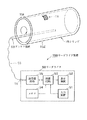
図1は、本発明に係るリーダライタ装置の第1の実施の形態を示す概略的な構成図であると共に、当該リーダライタ装置の使用形態を示す概略的な説明図である。
このリーダライタ装置160は、リーダライタ50と、アンテナ装置60と、配線56とを有する。リーダライタ50およびアンテナ装置60は、配線56によって互いに接続されている。
【0019】
リーダライタ50は、入力装置51と、表示装置52と、制御回路53と、メモリ54と、送受信回路55とを有する。送受信回路55は、入出力端子T1を介して配線56に接続されている。
【0020】
入力装置51は、リーダライタ装置160の操作者により、種々の情報が入力される。入力装置51に入力された情報(入力情報)は、制御回路53に供給される。入力情報としては、例えば、リーダライタ装置160のリード/ライトの命令情報、非接触式データキャリア11に書き込むシリンダ情報等がある。
【0021】
表示装置52は、制御回路53の表示制御の下で、種々の情報を表示する。
例えば、リーダライタ装置160の状態を示す情報、入力装置51の入力情報、非接触式データキャリア11との通信情報等の情報を、表示画面に表示する。
【0022】
メモリ54は、制御回路53の制御下で種々の情報を記憶する。
メモリ54は、入力装置51の入力情報、非接触式データキャリア11との通信情報等を記憶する。
【0023】
制御回路53は、リーダライタ装置160の全体を制御するコントローラであり、例えばマイクロコンピュータ(マイコン)により構成される。
制御回路53は、入力装置51の入力情報を表示装置52に供給し、入力情報を表示装置52の表示画面に表示させる。
【0024】
また、制御回路53は、メモリ54のアクセス制御、および、送受信回路55の制御を行う。例えば、制御回路53は、メモリ54に記憶された書込用のシリンダ情報を読み出し、当該シリンダ情報を送受信回路55に供給する。
さらに、制御回路53は、送受信回路55の受信情報をメモリ54および表示装置52に供給し、受信情報を表示装置52の表示画面に表示させる。
【0025】
送受信回路55は、制御回路53からの書込用のシリンダ情報および書込コマンド(ライトコマンド)を、アンテナ装置60を介して非接触式データキャリア11に供給する。
また、送受信回路55は、読出コマンド(リードコマンド)をアンテナ装置60を介して非接触式データキャリア11に供給し、非接触式データキャリア11との通信で得られたシリンダ情報等の通信情報を制御回路53に供給する。
【0026】
アンテナ装置60は、送受信回路55から配線56を介して供給された電気信号を電波に変換し、当該電波からなる信号を非接触式データキャリア11に送出する。
また、アンテナ装置60は、非接触式データキャリア11から送出された電波からなる信号を電気信号に変換し、当該電気信号を送受信回路55に供給する。
送受信回路55は、アンテナ装置60から配線56を介して供給された電気信号を増幅して制御回路53に供給する。
【0027】
アンテナ装置60は、棒状または略棒状の形状を有し、非接触式データキャリア11との通信を行う場合に、シリンダ15の空洞に挿入される。好ましくは、空洞への挿入後に、アンテナ装置60と非接触式データキャリア11とが近づくように、空洞内で内周に沿って回るようにアンテナ装置60を移動させる。
【0028】
このアンテナ装置60は、棒状または略棒状のアンテナと、当該アンテナを覆う絶縁性の保護膜とを有し、当該アンテナと配線56とが接続された構成としてもよい。
また、アンテナ装置60は、棒状または略棒状の絶縁基材と、当該絶縁基材に沿うアンテナと、絶縁基材上のアンテナを覆う絶縁性の保護膜とを有し、当該アンテナと配線56とが接続された構成としてもよい。
【0029】
シリンダ15は、鋼鉄等の金属の円筒であり、シリンダ15の外面15Zには、印刷情報に対応する銅メッキが施されている。シリンダ15の内面15Iの中央部または略中央部には、非接触式データキャリア11が取り付けてある。
アンテナ装置60の長さは、シリンダ15の開口部から非接触式データキャリア11までの距離よりも大きい。アンテナ装置60の長さは、図1ではシリンダ15の長さと同一または略同一になっており、例えばシリンダ15の長さの1倍程度〜数倍程度としてもよい。
【0030】
非接触式データキャリア11は、リーダライタ50との通信を行う。
この非接触式データキャリア11は、絶縁基材と、絶縁基材の表面に形成されたアンテナコイルと、アンテナコイルに接続されたマイクロコンピュータ(マイコン)とを有する。このマイコンは、例えば1チップマイコンにより構成される。非接触式データキャリア11は、前記絶縁基材のうちアンテナコイルの形成面が内側になるように、シリンダ15の内面15Iに取り付けてある。
【0031】
非接触式データキャリア11内のアンテナコイルは、リーダライタ装置160のアンテナ装置60から送出された電波を電気信号に変換し、当該電気信号をマイコンに供給する。
また、アンテナコイルは、マイコンからの電気信号を電波に変換し、当該電波からなる信号をアンテナ装置60に送出する。
【0032】
非接触式データキャリア11内のマイコンは、アンテナコイルからの電気信号に基づいて、種々の動作を行う。このマイコンは、例えば、書込コマンドと共にシリンダ情報を示す信号がアンテナコイルから供給された場合は、当該シリンダ情報をマイコン内のメモリに書き込んで記憶する。
また、このマイコンは、読出コマンドを示す信号がアンテナコイルから供給された場合は、メモリに記憶されたシリンダ情報を読み出し、当該シリンダ情報を示す信号をアンテナコイルに供給する。
【0033】
第2の実施の形態
図2は、本発明に係るリーダライタ装置の第2の実施の形態を示す概略的な構成図である。図3は、図2のリーダライタ装置の使用形態を示す概略的な説明図である。
リーダライタ装置170は、リーダライタ50と、アンテナ装置70と、配線57とを有する。リーダライタ50およびアンテナ装置70は、配線57によって互いに接続されている。
【0034】
リーダライタ50は、入力装置51と、表示装置52と、制御回路53と、メモリ54と、送受信回路55とを有する。送受信回路55は、入出力端子T1を介して配線57に接続されている。
【0035】
入力装置51は、リーダライタ装置170の操作者により、種々の情報が入力される。入力装置51に入力された情報(入力情報)は、制御回路53に供給される。入力情報としては、例えば、リーダライタ装置170のリード/ライトの命令情報、非接触式データキャリア11に書き込むシリンダ情報等がある。
【0036】
表示装置52は、制御回路53の表示制御の下で、種々の情報を表示する。
例えば、リーダライタ装置170の状態を示す情報、入力装置51の入力情報、非接触式データキャリア11との通信情報等の情報を、表示画面に表示する。
【0037】
メモリ54は、制御回路53の制御下で種々の情報を記憶する。
メモリ54は、入力装置51の入力情報、非接触式データキャリア11との通信情報等を記憶する。
【0038】
制御回路53は、リーダライタ装置170の全体を制御するコントローラであり、例えばマイクロコンピュータ(マイコン)により構成される。
制御回路53は、入力装置51の入力情報をメモリ54および表示装置52に供給し、入力情報を表示装置52の表示画面に表示させる。
【0039】
また、制御回路53は、メモリ54のアクセス制御、および、送受信回路55の制御を行う。例えば、制御回路53は、メモリ54に記憶された書込用のシリンダ情報を読み出し、当該シリンダ情報を送受信回路55に供給する。
さらに、制御回路53は、送受信回路55の受信情報を表示装置52に供給し、通信情報を表示装置52の表示画面に表示させる。
【0040】
送受信回路55は、制御回路53からの書込用のシリンダ情報および書込コマンド(ライトコマンド)をアンテナ装置70を介して非接触式データキャリア11に供給する。
また、送受信回路55は、読出コマンド(リードコマンド)をアンテナ装置60を介して非接触式データキャリア11に供給し、非接触式データキャリア11との通信で得られたシリンダ情報等の通信情報を制御回路53に供給する。
【0041】
アンテナ装置70は、送受信回路55から配線57を介して供給された電気信号を電波に変換し、当該電波からなる信号を非接触式データキャリア11に送出する。
また、アンテナ装置70は、非接触式データキャリア11から送出された電波からなる信号を電気信号に変換し、当該電気信号を送受信回路55に供給する。
送受信回路55は、アンテナ装置70から配線57を介して供給された電気信号を増幅して制御回路53に供給する。
【0042】
アンテナ装置70は、非接触式データキャリア11との通信を行う場合に、シリンダ15の空洞に挿入される。
このアンテナ装置70は、シリンダ15に挿入する方向を高さ方向とする柱状または略柱状の絶縁基材71と、絶縁基材71に取り付けられたアンテナ72と、当該絶縁基材71に取り付けられたアンテナ72を覆う不図示の絶縁性の保護膜とを有する。
【0043】
絶縁基材71の高さは、シリンダ15の開口部から非接触式データキャリア11までの距離よりも大きい。絶縁基材71には、絶縁基材71の先端付近からシリンダ15の空洞の長さの半分以上または略半分以上の長さにわたって、アンテナ72が螺旋状もしくは略螺旋状に巻き付けてある。巻付け回数は、1回以上であり、好適には複数回とする。
【0044】
絶縁基材71は、同一または略同一の外径の第1の部分である円柱部71Bと、円柱部71Bから外径が連続的に減少する第2の部分である傾斜部71Aとを有する。傾斜部71Aの外形は、円錐状または略円錐状の形状を有し、傾斜部71Aの頂点は、円柱部71Bの中心線上または略中心線上に位置する。
円柱部71Bの外径は、シリンダ15の内径よりも小さく、シリンダ15の内径の半分以上または略半分以上である。好適には、円柱部71Bの外径は、シリンダ15の内径よりも1cm程度〜2cm程度小さくする。
【0045】
シリンダ15は、鋼鉄等の金属の円筒であり、シリンダ15の外面15Zには、印刷情報に対応する銅メッキが施されている。シリンダ15の内面15Iの中央部または略中央部には、非接触式データキャリア11が取り付けてある。
アンテナ装置70の長さは、シリンダ15の開口部から非接触式データキャリア11までの距離よりも大きい。アンテナ装置70の長さは、図3ではシリンダ15の長さと同一または略同一になっており、例えばシリンダ15の長さの1倍程度〜数倍程度としてもよい。
【0046】
非接触式データキャリア11は、リーダライタ50との通信を行う。
この非接触式データキャリア11は、絶縁基材と、絶縁基材の表面に形成されたアンテナコイルと、アンテナコイルに接続されたマイコンとを有する。このマイコンは、例えば1チップマイコンにより構成される。非接触式データキャリア11は、前記絶縁基材のうちアンテナコイルの形成面が内側になるように、シリンダ15の内面15Iに取り付けてある。
【0047】
非接触式データキャリア11内のアンテナコイルは、リーダライタ装置170のアンテナ装置70から送出された電波を電気信号に変換し、当該電気信号をマイコンに供給する。
また、アンテナコイルは、マイコンからの電気信号を電波に変換し、当該電波からなる信号をアンテナ装置70に送出する。
【0048】
非接触式データキャリア11内のマイコンは、アンテナコイルからの電気信号に基づいて、種々の動作を行う。このマイコンは、例えば、書込コマンドと共にシリンダ情報を示す信号がアンテナコイルから供給された場合は、当該シリンダ情報をマイコン内のメモリに書き込んで記憶する。
また、このマイコンは、読出コマンドを示す信号がアンテナコイルから供給された場合は、メモリに記憶されたシリンダ情報を読み出し、当該シリンダ情報を示す信号をアンテナコイルに供給する。
【0049】
アンテナ装置70は傾斜部71Aを有するので、リーダライタ装置170の操作者は、アンテナ装置70をシリンダ15の空洞に容易かつスムーズに挿入することができる。また、挿入時における、アンテナ装置70の先端と非接触式データキャリア11との衝突を防止することが可能である。
また、絶縁基材71にアンテナ72を巻き付けてあるので、アンテナ装置70を空洞に挿入することで、シリンダ15の内面15Iに取り付けられた非接触式データキャリア11に対してアンテナ72を接近させることができる。
【0050】
なお、アンテナ72を複数本の導体線とし、当該複数本の導体線を平行または略平行に絶縁基材71に巻き付けてもよい。また、アンテナ72を1本の導体線を折り畳んだ構成とし、折り畳まれた導体線を絶縁基材71に巻き付けてもよい。
また、リーダライタ50において、制御回路53とメモリ54とを一体化した構成としてもよい。
また、上記実施の形態は本発明の例示であり、本発明は上記実施の形態に限定されない。
【0051】
【発明の効果】
以上に説明したように、本発明によれば、シリンダの内面に取り付けられた非接触式データキャリアとの通信を行うことが可能なリーダライタ装置と、このリーダライタ装置に使用可能なアンテナ装置とを提供することができる。
【図面の簡単な説明】
【図1】本発明に係るリーダライタ装置の第1の実施の形態を示す概略的な構成図である。
【図2】本発明に係るリーダライタ装置の第2の実施の形態を示す概略的な構成図である。
【図3】図2のリーダライタ装置を使用形態を示す概略的な説明図である。
【符号の説明】
11…非接触式データキャリア、15…シリンダ、15I…内面、15Z…外面、50…リーダライタ、51…入力装置、52…表示装置、53…制御回路、54…メモリ、55…送受信回路、56,57…配線、60,70…アンテナ装置、71…絶縁基材、71A…傾斜部、71B…円柱部、72…アンテナ、160,170…リーダライタ装置、T1…入出力端子。[0001]
BACKGROUND OF THE INVENTION
The present invention relates to a reader / writer device that performs communication with a non-contact data carrier, and an antenna device used in the reader / writer device.
[0002]
[Prior art]
In a rotary printing press, gravure printing may be performed using a cylinder.
The cylinder has a structure in which the outer surface of a metal cylinder such as steel is plated with copper. Generally, corrosive plate making is performed by transferring a carbon tissue onto which a positive film is baked.
[0003]
When various cylinders are manufactured for gravure printing, management of cylinders and cylinder information (cylinder information) is necessary. The cylinder information includes, for example, information on printing contents of the cylinder, information on ink used for the cylinder and printing paper, and the like.
[0004]
[Problems to be solved by the invention]
By attaching a non-contact type data carrier storing cylinder information to the inner surface of the cylinder, the cylinder information can be held in the cylinder.
However, since the material of the cylinder is a conductor, the communication distance of the non-contact type data carrier attached to the inner surface of the cylinder is reduced, and it is difficult to perform communication from the outside of the cylinder.
[0005]
An object of the present invention is to provide a reader / writer device capable of communicating with a non-contact type data carrier attached to the inner surface of a cylinder, and an antenna device usable for the reader / writer device.
[0006]
[Means for Solving the Problems]
According to the present invention, when connected to a reader / writer that communicates with a non-contact type data carrier attached to the inner surface of a printing cylinder, and communicates between the reader / writer and the non-contact type data carrier. An antenna device inserted into the cavity of the cylinder,
A columnar or substantially columnar insulating base material whose height direction is the direction of insertion into the cylinder; and
An antenna attached to the insulating substrate;
Have
The height of the insulating substrate is greater than the distance from the opening of the cylinder to the non-contact data carrier;
The antenna is spirally or substantially spirally wound on the insulating base material from the vicinity of the front end of the insulating base material over a length of half or more of the length of the cavity of the cylinder.
An antenna device is provided.
[0007]
Further, according to the present invention, the reader / writer is connected to a non-contact type data carrier attached to the inner surface of the printing cylinder and communicates between the reader / writer and the non-contact type data carrier. In this case, the antenna device is inserted into the cavity of the cylinder, and a columnar or substantially columnar insulating base material whose height direction is the direction of insertion into the cylinder, and
An antenna attached to the insulating substrate;
Have
The insulating base has a first portion having the same or substantially the same outer diameter, and a second portion in which the outer diameter continuously decreases from the first portion,
The tip of the second part is located on or substantially on the center line of the first part,
An antenna device is provided.
[0008]
Preferably, the outer diameter of the first portion is smaller than the inner diameter of the cylinder and is not less than half or substantially more than half of the inner diameter of the cylinder.
[0009]
Moreover, preferably, it further has an insulating protective layer covering the antenna attached to the insulating substrate.
[0010]
According to the present invention, a reader / writer that communicates with a non-contact type data carrier attached to the inner surface of a printing cylinder, and connected to the reader / writer, between the reader / writer and the non-contact type data carrier. in an antenna device that is inserted into the cavity of the cylinder when performing communication,
The antenna device has a columnar or substantially columnar insulating base material whose height direction is inserted in the cylinder, and an antenna attached to the insulating base material,
The height of the insulating substrate is greater than the distance from the opening of the cylinder to the non-contact data carrier;
The antenna is spirally or substantially spirally wound on the insulating base material from the vicinity of the front end of the insulating base material over a length of half or more of the length of the cavity of the cylinder .
A reader / writer device is provided.
[0011]
According to the invention, a reader / writer that communicates with a non-contact type data carrier attached to an inner surface of a printing cylinder, and connected to the reader / writer, the reader / writer and the non-contact type data carrier An antenna device inserted into the cavity of the cylinder when communicating between
The antenna device has a columnar or substantially columnar insulating base material whose height direction is inserted in the cylinder, and an antenna attached to the insulating base material,
The insulating base has a first portion having the same or substantially the same outer diameter, and a second portion in which the outer diameter continuously decreases from the cylindrical portion,
The tip of the second part is located on or substantially on the center line of the first part,
A reader / writer device is provided.
[0012]
Preferably, the outer diameter of the first portion is smaller than the inner diameter of the cylinder and is not less than half or substantially more than half of the inner diameter of the cylinder.
[0013]
Preferably, the antenna device further includes an insulating protective layer that covers the antenna attached to the insulating base.
[0014]
Preferably, the reader / writer has a display device for displaying communication information with the non-contact data carrier.
[0016]
When communicating between a contactless data carrier attached to the inner surface of a cylinder and a reader / writer, the antenna device can be brought closer to the contactless data carrier by inserting the antenna device into the cavity of the cylinder. In addition, even when the communication distance of the non-contact type data carrier is small, communication with the reader / writer is possible.
For example, the antenna can be brought close to a non-contact type data carrier by inserting a columnar or substantially columnar insulating substrate with an antenna attached thereto into the cavity.
[0017]
DETAILED DESCRIPTION OF THE INVENTION
Hereinafter, embodiments of the present invention will be described with reference to the accompanying drawings.
[0018]
First Embodiment FIG. 1 is a schematic configuration diagram showing a first embodiment of a reader / writer apparatus according to the present invention, and a schematic diagram showing a usage pattern of the reader / writer apparatus. FIG.
The reader / writer device 160 includes a reader / writer 50, an antenna device 60, and a
[0019]
The reader / writer 50 includes an
[0020]
Various information is input to the
[0021]
The
For example, information such as information indicating the state of the reader / writer device 160, input information of the
[0022]
The
The
[0023]
The
The
[0024]
The
Further, the
[0025]
The transmission /
In addition, the transmission /
[0026]
The antenna device 60 converts the electric signal supplied from the transmission /
Further, the antenna device 60 converts a signal composed of radio waves transmitted from the
The transmission /
[0027]
The antenna device 60 has a rod shape or a substantially rod shape, and is inserted into the cavity of the cylinder 15 when communicating with the non-contact
[0028]
The antenna device 60 may include a rod-shaped or substantially rod-shaped antenna and an insulating protective film that covers the antenna, and the antenna and the
The antenna device 60 includes a rod-shaped or substantially rod-shaped insulating base material, an antenna along the insulating base material, and an insulating protective film that covers the antenna on the insulating base material. May be connected.
[0029]
The cylinder 15 is a metal cylinder such as steel, and the
The length of the antenna device 60 is larger than the distance from the opening of the cylinder 15 to the non-contact
[0030]
The non-contact
This non-contact
[0031]
The antenna coil in the non-contact
The antenna coil converts an electric signal from the microcomputer into a radio wave, and sends a signal composed of the radio wave to the antenna device 60.
[0032]
The microcomputer in the non-contact
In addition, when a signal indicating a read command is supplied from the antenna coil, the microcomputer reads cylinder information stored in the memory and supplies a signal indicating the cylinder information to the antenna coil.
[0033]
Second Embodiment FIG. 2 is a schematic configuration diagram showing a second embodiment of the reader / writer device according to the present invention. FIG. 3 is a schematic explanatory view showing a usage pattern of the reader / writer device of FIG.
The reader / writer device 170 includes the reader / writer 50, the antenna device 70, and the
[0034]
The reader / writer 50 includes an
[0035]
Various information is input to the
[0036]
The
For example, information such as information indicating the state of the reader / writer device 170, input information of the
[0037]
The
The
[0038]
The
The
[0039]
The
Further, the
[0040]
The transmission /
In addition, the transmission /
[0041]
The antenna device 70 converts an electric signal supplied from the transmission /
Further, the antenna device 70 converts a signal composed of a radio wave transmitted from the
The transmission /
[0042]
The antenna device 70 is inserted into the cavity of the cylinder 15 when communicating with the non-contact
The antenna device 70 includes a columnar or substantially columnar insulating
[0043]
The height of the insulating
[0044]
The insulating
The outer diameter of the
[0045]
The cylinder 15 is a metal cylinder such as steel, and the
The length of the antenna device 70 is larger than the distance from the opening of the cylinder 15 to the non-contact
[0046]
The non-contact
The non-contact
[0047]
The antenna coil in the non-contact
Further, the antenna coil converts an electric signal from the microcomputer into a radio wave, and sends a signal composed of the radio wave to the antenna device 70.
[0048]
The microcomputer in the non-contact
In addition, when a signal indicating a read command is supplied from the antenna coil, the microcomputer reads cylinder information stored in the memory and supplies a signal indicating the cylinder information to the antenna coil.
[0049]
Since the antenna device 70 has the inclined
Further, since the
[0050]
The
In the reader / writer 50, the
Moreover, the said embodiment is an illustration of this invention and this invention is not limited to the said embodiment.
[0051]
【The invention's effect】
As described above, according to the present invention, the reader / writer device capable of communicating with the non-contact data carrier attached to the inner surface of the cylinder, and the antenna device usable for the reader / writer device, Can be provided.
[Brief description of the drawings]
FIG. 1 is a schematic configuration diagram showing a first embodiment of a reader / writer device according to the present invention.
FIG. 2 is a schematic configuration diagram showing a second embodiment of a reader / writer device according to the present invention.
FIG. 3 is a schematic explanatory diagram showing a usage pattern of the reader / writer device of FIG. 2;
[Explanation of symbols]
DESCRIPTION OF
Claims (9)
前記シリンダに挿入する方向を高さ方向とする柱状または略柱状の絶縁基材と、
前記絶縁基材に取り付けられたアンテナと
を有し、
前記絶縁基材の高さは、前記シリンダの開口部から前記非接触式データキャリアまでの距離よりも大きく、
前記絶縁基材には、前記絶縁基材の先端付近から前記シリンダの空洞の長さの半分以上または略半分以上の長さにわたって、前記アンテナが螺旋状もしくは略螺旋状に巻き付けてある、
アンテナ装置。Connected to a reader / writer that communicates with a non-contact type data carrier attached to the inner surface of a cylinder for printing, and when communicating between the reader / writer and the non-contact type data carrier, An antenna device to be inserted,
A columnar or substantially columnar insulating base material whose height direction is the direction of insertion into the cylinder; and
An antenna attached to the insulating substrate;
Have
The height of the insulating substrate is greater than the distance from the opening of the cylinder to the non-contact data carrier;
The antenna is spirally or substantially spirally wound on the insulating base material from the vicinity of the tip of the insulating base material over a length of half or more of the cavity length of the cylinder.
Antenna device.
前記シリンダに挿入する方向を高さ方向とする柱状または略柱状の絶縁基材と、A columnar or substantially columnar insulating base material whose height direction is the direction of insertion into the cylinder; and
前記絶縁基材に取り付けられたアンテナとAn antenna attached to the insulating substrate;
を有し、Have
前記絶縁基材は、The insulating substrate is
同一または略同一の外径の第1の部分と、A first portion having the same or substantially the same outer diameter;
前記第1の部分から外径が連続的に減少する第2の部分とA second portion whose outer diameter continuously decreases from the first portion;
を有し、Have
前記第2の部分の先端は、前記第1の部分の中心線上または略中心線上に位置する、The tip of the second part is located on or substantially on the center line of the first part,
アンテナ装置。Antenna device.
請求項2に記載のアンテナ装置。The outer diameter of the first portion is smaller than the inner diameter of the cylinder, and is half or more or substantially half or more of the inner diameter of the cylinder.
The antenna device according to claim 2 .
請求項1、2、3の何れかに記載のアンテナ装置。An insulating protective layer covering the antenna attached to the insulating substrate;
The antenna device according to claim 1 .
前記リーダライタに接続され、前記リーダライタと前記非接触式データキャリアとの間で通信を行う場合に前記シリンダの空洞に挿入されるアンテナ装置と
を有し、
前記アンテナ装置は、
前記シリンダに挿入する方向を高さ方向とする柱状または略柱状の絶縁基材と、
前記絶縁基材に取り付けられたアンテナと
を有し、
前記絶縁基材の高さは、前記シリンダの開口部から前記非接触式データキャリアまでの距離よりも大きく、
前記絶縁基材には、前記絶縁基材の先端付近から前記シリンダの空洞の長さの半分以上または略半分以上の長さにわたって、前記アンテナが螺旋状もしくは略螺旋状に巻き付けてある、
リーダライタ装置。A reader / writer that communicates with a non-contact data carrier attached to the inner surface of a cylinder for printing;
An antenna device connected to the reader / writer and inserted into a cavity of the cylinder when communicating between the reader / writer and the non-contact data carrier;
Have
The antenna device is
A columnar or substantially columnar insulating base material whose height direction is the direction of insertion into the cylinder; and
An antenna attached to the insulating substrate;
Have
The height of the insulating substrate is greater than the distance from the opening of the cylinder to the non-contact data carrier;
The antenna is spirally or substantially spirally wound on the insulating base material from the vicinity of the tip of the insulating base material over a length of half or more of the cavity length of the cylinder .
Reader / writer device.
前記リーダライタに接続され、前記リーダライタと前記非接触式データキャリアとの間で通信を行う場合に前記シリンダの空洞に挿入されるアンテナ装置とAn antenna device connected to the reader / writer and inserted into a cavity of the cylinder when communicating between the reader / writer and the non-contact data carrier;
を有し、Have
前記アンテナ装置は、The antenna device is
前記シリンダに挿入する方向を高さ方向とする柱状または略柱状の絶縁基材と、A columnar or substantially columnar insulating base material whose height direction is the direction of insertion into the cylinder; and
前記絶縁基材に取り付けられたアンテナとAn antenna attached to the insulating substrate;
を有し、Have
前記絶縁基材は、The insulating substrate is
同一または略同一の外径の第1の部分と、A first portion having the same or substantially the same outer diameter;
前記円柱部から外径が連続的に減少する第2の部分とA second portion whose outer diameter continuously decreases from the cylindrical portion;
を有し、Have
前記第2の部分の先端は、前記第1の部分の中心線上または略中心線上に位置する、The tip of the second part is located on or substantially on the center line of the first part,
リーダライタ装置。Reader / writer device.
請求項6に記載のリーダライタ装置。The outer diameter of the first portion is smaller than the inner diameter of the cylinder, and is half or more or substantially half or more of the inner diameter of the cylinder.
The reader / writer device according to claim 6 .
請求項5、6、7の何れかに記載のリーダライタ装置。The antenna device further includes an insulating protective layer that covers the antenna attached to the insulating substrate.
The reader / writer device according to claim 5 .
請求項5、6、7、8の何れかに記載のリーダライタ装置。The reader / writer has a display device that displays communication information with the non-contact data carrier.
The reader / writer device according to claim 5 .
Priority Applications (1)
| Application Number | Priority Date | Filing Date | Title |
|---|---|---|---|
| JP2000178811A JP4592876B2 (en) | 2000-06-14 | 2000-06-14 | Antenna device and reader / writer device |
Applications Claiming Priority (1)
| Application Number | Priority Date | Filing Date | Title |
|---|---|---|---|
| JP2000178811A JP4592876B2 (en) | 2000-06-14 | 2000-06-14 | Antenna device and reader / writer device |
Publications (2)
| Publication Number | Publication Date |
|---|---|
| JP2001357366A JP2001357366A (en) | 2001-12-26 |
| JP4592876B2 true JP4592876B2 (en) | 2010-12-08 |
Family
ID=18680179
Family Applications (1)
| Application Number | Title | Priority Date | Filing Date |
|---|---|---|---|
| JP2000178811A Expired - Fee Related JP4592876B2 (en) | 2000-06-14 | 2000-06-14 | Antenna device and reader / writer device |
Country Status (1)
| Country | Link |
|---|---|
| JP (1) | JP4592876B2 (en) |
Families Citing this family (7)
| Publication number | Priority date | Publication date | Assignee | Title |
|---|---|---|---|---|
| JP2005165839A (en) * | 2003-12-04 | 2005-06-23 | Nippon Signal Co Ltd:The | Reader/writer, ic tag, article control device, and optical disk device |
| JP2006039967A (en) | 2004-07-27 | 2006-02-09 | Fujitsu Ltd | Disk tag reader |
| JP4972911B2 (en) * | 2005-11-18 | 2012-07-11 | 株式会社日立製作所 | RFID readers used in RFID built-in cable systems |
| JP2007156640A (en) * | 2005-12-01 | 2007-06-21 | Kobe Steel Ltd | Antenna for ic tag, antenna for ic tag access device, antenna system in ic tag system |
| JP4303767B2 (en) * | 2007-10-02 | 2009-07-29 | 株式会社神戸製鋼所 | RFID tag detection method, RFID tag detection system |
| EP2226746B1 (en) * | 2007-11-28 | 2012-01-11 | Fujitsu Limited | Metallic pipe managed by wireless ic tag, and the wireless ic tag |
| CN102273012B (en) * | 2009-01-09 | 2013-11-20 | 株式会社村田制作所 | Wireless IC device, wireless IC module and wireless IC module manufacturing method |
Citations (2)
| Publication number | Priority date | Publication date | Assignee | Title |
|---|---|---|---|---|
| JP2001151313A (en) * | 1999-11-25 | 2001-06-05 | Toppan Printing Co Ltd | Metal article with noncontact tag and metal article management system |
| JP2001179932A (en) * | 1999-12-28 | 2001-07-03 | Mitsubishi Materials Corp | Plate cylinder discriminating tag of printing machine and plate cylinder discriminating device using the same |
-
2000
- 2000-06-14 JP JP2000178811A patent/JP4592876B2/en not_active Expired - Fee Related
Patent Citations (2)
| Publication number | Priority date | Publication date | Assignee | Title |
|---|---|---|---|---|
| JP2001151313A (en) * | 1999-11-25 | 2001-06-05 | Toppan Printing Co Ltd | Metal article with noncontact tag and metal article management system |
| JP2001179932A (en) * | 1999-12-28 | 2001-07-03 | Mitsubishi Materials Corp | Plate cylinder discriminating tag of printing machine and plate cylinder discriminating device using the same |
Also Published As
| Publication number | Publication date |
|---|---|
| JP2001357366A (en) | 2001-12-26 |
Similar Documents
| Publication | Publication Date | Title |
|---|---|---|
| CN1689825B (en) | RF tag reader/writer and printer | |
| JP4592876B2 (en) | Antenna device and reader / writer device | |
| JP4324059B2 (en) | IC tag mounting harness | |
| US9024725B2 (en) | Communication terminal and information processing system | |
| EP1641140B1 (en) | Data communication device | |
| JP4704751B2 (en) | Communication processing via antenna for smart cards and related devices | |
| WO2005064528A1 (en) | Radio tag issuing device | |
| EP0948083A3 (en) | Loop antenna device and its use in a data processing apparatus with a removal data storing medium | |
| JP2006148462A (en) | Rfid tag | |
| CN101019134A (en) | Adapter for memory card | |
| JP2008011499A (en) | Planar antenna for radio frequency identification tag | |
| JP2007150642A (en) | Interrogator for wireless tag, antenna for wireless tag, wireless tag system, and wireless tag selector | |
| JPWO2017134917A1 (en) | Electronic pen | |
| CA2933263C (en) | Contactless communications antenna for payment terminals | |
| US20100147583A1 (en) | Cable | |
| CN105684215B (en) | Antenna assembly and electronic equipment | |
| CN202838351U (en) | Radio frequency identification device for near-filed communication | |
| JP2005056118A (en) | Non-contact information medium and communication system using it | |
| JP2002526868A (en) | Tamper resistant packaging for integrated circuit cards with telecommunications means | |
| EP2977885A1 (en) | Information input device, control method, and control program | |
| JP2000293655A (en) | Tag for identification of article and device for identifying article using the tag | |
| JP2001322242A (en) | Antenna unit and reader/writer device | |
| JP3596056B2 (en) | Identification system and coil used therein | |
| JP2001353842A (en) | Non-contact type data carrier and cylinder apparatus | |
| JP6938235B2 (en) | Non-contact communication medium |
Legal Events
| Date | Code | Title | Description |
|---|---|---|---|
| A621 | Written request for application examination |
Free format text: JAPANESE INTERMEDIATE CODE: A621 Effective date: 20070323 |
|
| A977 | Report on retrieval |
Free format text: JAPANESE INTERMEDIATE CODE: A971007 Effective date: 20100315 |
|
| A131 | Notification of reasons for refusal |
Free format text: JAPANESE INTERMEDIATE CODE: A131 Effective date: 20100330 |
|
| A521 | Request for written amendment filed |
Free format text: JAPANESE INTERMEDIATE CODE: A523 Effective date: 20100531 |
|
| TRDD | Decision of grant or rejection written | ||
| A01 | Written decision to grant a patent or to grant a registration (utility model) |
Free format text: JAPANESE INTERMEDIATE CODE: A01 Effective date: 20100817 |
|
| A01 | Written decision to grant a patent or to grant a registration (utility model) |
Free format text: JAPANESE INTERMEDIATE CODE: A01 |
|
| A61 | First payment of annual fees (during grant procedure) |
Free format text: JAPANESE INTERMEDIATE CODE: A61 Effective date: 20100915 |
|
| FPAY | Renewal fee payment (event date is renewal date of database) |
Free format text: PAYMENT UNTIL: 20130924 Year of fee payment: 3 |
|
| R150 | Certificate of patent or registration of utility model |
Free format text: JAPANESE INTERMEDIATE CODE: R150 |
|
| LAPS | Cancellation because of no payment of annual fees |