JP4591925B2 - Method for manufacturing an artificial hip joint - Google Patents
Method for manufacturing an artificial hip joint Download PDFInfo
- Publication number
- JP4591925B2 JP4591925B2 JP2005073496A JP2005073496A JP4591925B2 JP 4591925 B2 JP4591925 B2 JP 4591925B2 JP 2005073496 A JP2005073496 A JP 2005073496A JP 2005073496 A JP2005073496 A JP 2005073496A JP 4591925 B2 JP4591925 B2 JP 4591925B2
- Authority
- JP
- Japan
- Prior art keywords
- hip joint
- stem portion
- artificial hip
- titanium
- manufacturing
- Prior art date
- Legal status (The legal status is an assumption and is not a legal conclusion. Google has not performed a legal analysis and makes no representation as to the accuracy of the status listed.)
- Expired - Fee Related
Links
Images


Classifications
-
- A—HUMAN NECESSITIES
- A61—MEDICAL OR VETERINARY SCIENCE; HYGIENE
- A61F—FILTERS IMPLANTABLE INTO BLOOD VESSELS; PROSTHESES; DEVICES PROVIDING PATENCY TO, OR PREVENTING COLLAPSING OF, TUBULAR STRUCTURES OF THE BODY, e.g. STENTS; ORTHOPAEDIC, NURSING OR CONTRACEPTIVE DEVICES; FOMENTATION; TREATMENT OR PROTECTION OF EYES OR EARS; BANDAGES, DRESSINGS OR ABSORBENT PADS; FIRST-AID KITS
- A61F2/00—Filters implantable into blood vessels; Prostheses, i.e. artificial substitutes or replacements for parts of the body; Appliances for connecting them with the body; Devices providing patency to, or preventing collapsing of, tubular structures of the body, e.g. stents
- A61F2/02—Prostheses implantable into the body
- A61F2/30—Joints
- A61F2/32—Joints for the hip
- A61F2/36—Femoral heads ; Femoral endoprostheses
-
- A—HUMAN NECESSITIES
- A61—MEDICAL OR VETERINARY SCIENCE; HYGIENE
- A61F—FILTERS IMPLANTABLE INTO BLOOD VESSELS; PROSTHESES; DEVICES PROVIDING PATENCY TO, OR PREVENTING COLLAPSING OF, TUBULAR STRUCTURES OF THE BODY, e.g. STENTS; ORTHOPAEDIC, NURSING OR CONTRACEPTIVE DEVICES; FOMENTATION; TREATMENT OR PROTECTION OF EYES OR EARS; BANDAGES, DRESSINGS OR ABSORBENT PADS; FIRST-AID KITS
- A61F2/00—Filters implantable into blood vessels; Prostheses, i.e. artificial substitutes or replacements for parts of the body; Appliances for connecting them with the body; Devices providing patency to, or preventing collapsing of, tubular structures of the body, e.g. stents
- A61F2/02—Prostheses implantable into the body
- A61F2/30—Joints
- A61F2002/30001—Additional features of subject-matter classified in A61F2/28, A61F2/30 and subgroups thereof
Description
本発明は、拡散接合法により接合されたメッシュ層を有する人工股関節の製造方法に関する。 The present invention relates to a method for manufacturing an artificial hip joint having a mesh layer bonded by a diffusion bonding method.
整形外科において用いられる人工股関節は、生体親和性に加え、使用状況に応じた負荷や摺動に耐える構成であることが要求される。これらの要求を満たす金属系材料としては、SUS316、Co−Cr合金、チタン、チタン合金がある。人工股関節は、生体親和性、負荷性および摺動性を考慮してこれらの金属系材料からチタンやチタン合金が選定される。 Artificial hip joints used in orthopedics are required to have a structure that can withstand loads and sliding according to usage conditions in addition to biocompatibility. Examples of metal materials that satisfy these requirements include SUS316, Co—Cr alloy, titanium, and titanium alloy. For an artificial hip joint, titanium or a titanium alloy is selected from these metal materials in consideration of biocompatibility, loadability, and slidability.
人工股関節は、ステム部とステム部の近位端にオフセット連接されたネック部とを有する構成である。人工股関節は、ステム部の外面に骨セメントとして作用するポリメチルアクリレートを塗布し、ステム部を骨セメント層を介して大腿骨の近位部骨髄腔に装着することで大腿骨に固定される。 The artificial hip joint includes a stem portion and a neck portion offset-connected to the proximal end of the stem portion. The artificial hip joint is fixed to the femur by applying polymethylacrylate acting as a bone cement to the outer surface of the stem portion, and attaching the stem portion to the proximal bone marrow cavity of the femur via the bone cement layer.
人工股関節は、ステム部を骨セメント層を介し大腿骨に固定するので、長期間の使用により塗布した骨セメント層が劣化し、ステム部と大腿骨の骨皮質との間にゆるみが生じ、大腿骨に対する結合力が低下してしまうことがある。 In an artificial hip joint, the stem part is fixed to the femur via the bone cement layer, so that the bone cement layer applied after long-term use deteriorates, and loosening occurs between the stem part and the bone cortex of the femur. The bond strength to the bone may be reduced.
一方、大腿骨に対する支持面に多孔質金属パッドを接合して多孔質面に形成し、多孔質面に形成した細孔に大腿骨の新生骨を侵入させて大腿骨に確実に結合することで大腿骨に対する結合力を高めるようにした人工関節が開発されている。
上記人工関節は、人工関節本体をチタンまたはチタン合金により成形し、多孔質金属パッドをCo−Cr合金またはステンレススチール合金により成形し、人工関節本体と多孔質金属パッドをレーザー光線による接合手段により接合することで構成される(例えば、特許文献1)。
On the other hand, a porous metal pad is joined to the support surface for the femur to form a porous surface, and the new bone of the femur is infiltrated into the pores formed on the porous surface to securely bond to the femur. Artificial joints have been developed that increase the bond strength to the femur.
In the artificial joint, the artificial joint body is formed of titanium or a titanium alloy, the porous metal pad is formed of a Co—Cr alloy or a stainless steel alloy, and the artificial joint body and the porous metal pad are bonded by a laser beam bonding means. (For example, Patent Document 1).
しかし、上記人工関節は、大腿骨に対する支持面を有する人工膝関節に適用することはできても、大腿骨の近位部骨髄腔に装着するステム部を有する人工股関節に適用されるものではない。 However, the artificial joint can be applied to an artificial knee joint having a supporting surface for the femur, but is not applied to an artificial hip joint having a stem portion to be attached to the proximal bone marrow cavity of the femur. .
上記人工股関節は、ステム部とステム部の近位端にオフセット連接されたネック部とを有し、ステム部の断面形状が卵形であるため、ステム部の表面にチタン線またはチタン粒子を従来の拡散接合法により接合することは困難である。 The artificial hip joint has a stem portion and a neck portion offset-connected to the proximal end of the stem portion, and the stem portion has an oval cross-sectional shape, so that titanium wire or titanium particles are conventionally used on the surface of the stem portion. It is difficult to join by the diffusion bonding method.
本発明は、上記した点を考慮してなされたもので、ステム部に配置されたメッシュ層を半径方向内方の加圧力によりステム部に確実に拡散接合することができる人工股関節の製造方法を提供することを目的とする。 The present invention has been made in consideration of the above-described points, and provides a method for manufacturing an artificial hip joint that can securely diffuse and bond a mesh layer disposed on a stem portion to the stem portion by a radially inward pressurizing force. The purpose is to provide.
本発明の人工股関節の製造方法は、チタン材料またはチタン合金材料から成形されたステム部を有する人工股関節本体を設け、チタン材料またはチタン合金材料より熱膨張係数が大きい金属材料から成形された複数のセグメントを有する加圧治具を設け、人工股関節本体のステム部の表面にチタン材料またはチタン合金材料のメッシュ層を積層し、加圧治具をステム部のメッシュ層を囲むように配置し、チタン材料またはチタン合金材料より熱膨張係数が小さい金属材料で形成した線材を加圧治具の外面に巻き付け、これら全体を真空中あるいは不活性ガスの雰囲気中で加熱処理し、加圧治具の半径方向内方を向く加圧力によりメッシュ層をステム部に拡散接合することで構成される。 The artificial hip joint manufacturing method of the present invention includes an artificial hip joint body having a stem portion formed from a titanium material or a titanium alloy material, and a plurality of metal materials formed from a metal material having a thermal expansion coefficient larger than that of the titanium material or the titanium alloy material. A pressure jig having segments is provided, a mesh layer of titanium material or titanium alloy material is laminated on the surface of the stem portion of the artificial hip joint body, and the pressure jig is arranged so as to surround the mesh layer of the stem portion. A wire formed of a metal material having a smaller thermal expansion coefficient than the material or titanium alloy material is wound around the outer surface of the pressurizing jig, and the whole is heat-treated in a vacuum or in an inert gas atmosphere, and the radius of the pressurizing jig The mesh layer is formed by diffusion bonding to the stem portion with a pressing force directed inward in the direction.
本発明によれば、加圧治具を構成する金属材料の熱膨張係数をチタン材料またはチタン合金材料の熱膨張係数より大きく、加圧治具の外面に巻き付けられる線材の金属材料の熱膨張係数をチタン材料またはチタン合金材料の熱膨張係数より小さくすることで、真空中あるいは不活性ガスの雰囲気中で加熱処理する際に発生する加圧治具の熱膨張力を半径方向内方に向けることで、メッシュ層をステム部に確実に拡散接合することができる。 According to the present invention, the thermal expansion coefficient of the metal material constituting the pressure jig is larger than the thermal expansion coefficient of the titanium material or the titanium alloy material, and the thermal expansion coefficient of the metal material of the wire wound around the outer surface of the pressure jig. By making the thermal expansion coefficient smaller than that of titanium material or titanium alloy material, the thermal expansion force of the pressurizing jig generated during heat treatment in a vacuum or inert gas atmosphere is directed radially inward. Thus, the mesh layer can be securely diffusion bonded to the stem portion.
以下、本発明の実施の形態について図面を参照して説明する。
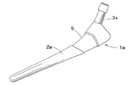
図1は、本発明による人工股関節の製造方法により作られた人工股関節の斜視図である。
Hereinafter, embodiments of the present invention will be described with reference to the drawings.
FIG. 1 is a perspective view of an artificial hip joint made by a method for manufacturing an artificial hip joint according to the present invention.
本発明による人工股関節の製造方法により作られた人工股関節1は、図1に示すように、大腿骨の近位部骨髄腔に固定されるステム部2と、ステム部2の近位端にオフセット連接されたネック部3とを有する。ステム部2のネック部3に近い部位に多孔質面4が形成されている。多孔質面4は、複数枚のチタンまたはチタン合金製メッシュシートを積層したメッシュシート積層体により形成される。各メッシュシートは、縦方向および横方向に規則的に配列した略円形の細孔を有する。メッシュシートの厚さおよび細孔の孔径は、使用条件に応じて選定される。
As shown in FIG. 1, an
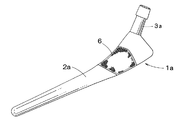
本発明による人工股関節の製造方法に用いられる人工股関節本体1aは、チタン材料またはチタン合金材料により成形されている。人工股関節本体1aは、図2に示すように、ステム部2aと、ステム部2aにオフセット連接されたネック部3aとを有する。ステム部2aのネック部3aに近い部位に周方向に延びる環状溝5が形成されている。環状溝5は、その深さを環状溝5に配置されるメッシュシート積層体6の厚さに対応させている。メッシュシート積層体6は、ステム部2aの外面に設けた環状溝5にその上面がステム部2aの外面と同一面になるように配置されることが好ましい。
The artificial hip
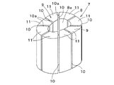
本発明による人工股関節の製造方法に用いられる加圧治具7は、チタン材料またはチタン合金材料より熱膨張係数が大きい金属材料であるSUS304ステンレス鋼材により成形された円筒体8から形成されている。円筒体8は、図3に示すように、ステム部2aの卵形断面形状に対応した内部空間8aを有する。円筒体8は、卵形の長径線に沿って2つ割りされた半体9,9を有する。各半体9は、半径方向中間位置に連結部10aを有する3つの半径方向に延びるスリット10,10,10により互いに連結された4つのセグメント片11,11,11,11を形成する。加圧治具7は、チタン材料またはチタン合金材料より熱膨張係数が大きい金属材料であれば、鉄、ニッケル、またはこれらの合金であってもよい。
The pressurizing
本発明による人工股関節の製造方法に用いられる加圧治具を固定するための線材12は、チタン材料またはチタン合金材料より熱膨張係数が小さい金属材料であるモリブデン材またはタングステン材から形成されている。
A
金属材料の熱膨張係数を下表に示す。
つぎに、本発明による人工股関節の製造方法を説明する。
準備段階として、人工股関節本体1aをチタン材料またはチタン合金材料により成形する。加圧治具7をSUS304ステンレス鋼、鉄又はニッケルにより成形する。線材12をモリブデンまたはタングステンで形成する。
Next, a method for manufacturing an artificial hip joint according to the present invention will be described.
As a preparation stage, the artificial
第1段階として、図2に示す人工股関節本体1aを設け、人工股関節本体1aのステム部2aに形成した環状溝5に、チタン材料またはチタン合金材料のメッシュシート積層体6を図4に示すように配置する。この場合、メッシュシート積層体6を、ステム部2aの外面に設けた環状溝5にその上面がステム部2aの外面と同一面になるように配置することが好ましい。
As a first step, the artificial
第2段階として、図3に示す2つ割りした加圧治具7を設け、この2つ割りした加圧治具7を、図5に示すように、人工股関節本体1aのメッシュシート積層体6を配置したステム部2aを囲むように配置する。加圧治具7は、内部空間がステム部2aに外面形状に対応しているので、位置決めすることなくメッシュシート積層体6を配置したステム部2aに密着される。
As a second stage, a
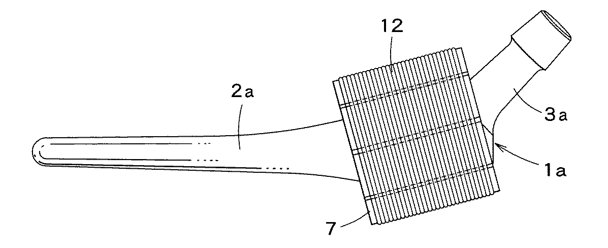
第3段階として、線材12を、図6に示すように、2つ割りした加圧治具7の外面に巻き付ける。これにより、2つ割りした加圧治具7は、人工股関節本体1aのステム部2aに固定される。
As a third stage, the
第4段階として、これら全体を図示しない真空加熱処理装置の真空室に配置し、真空加熱処理装置を作動することにより、人工股関節本体1aを真空中あるいは不活性ガスの雰 囲気中で、温度800℃で15分間処理する。
As a fourth stage, the whole is placed in a vacuum chamber of a vacuum heat treatment apparatus (not shown), and the vacuum heat treatment apparatus is operated to place the artificial
真空あるいは不活性ガスの雰囲気における加熱中において、チタン材料またはチタン合金材料より熱膨張係数が大きい金属材料で成形された加圧治具7は、チタン材料またはチタン合金材料により成形された人工股関節本体1aより大きく膨張する。しかし、加圧治具7は、外面をチタン材料またはチタン合金材料より熱膨張係数が小さい金属材料の線材12で拘束され、加圧治具7の半径方向外方の膨張が抑制される。そのため、加圧治具7は、半径方向内方に膨張する。
During heating in a vacuum or an inert gas atmosphere, a
加圧治具7の各半体は、連結部10aを有する半径方向に延びるスリットにより複数のセグメント片11を形成しているので、各セグメント片11は、互いに連結した状態で半径方向内方に膨張し、半径方向内方の加圧力を発生する。加圧治具7の半径方向内方の加圧力は、メッシュシート積層体6をステム部2aの全周からほぼ均一に加圧し、メッシュシート積層体6をステム部2aに拡散接合する。
Each half of the
本発明による人工股関節の製造方法によりり作られた人工股関節は、メッシュシート積層体をステム部の全周方向から加圧するので、メッシュシート積層体とステム部と接合強度を高くでき、メッシュシート積層体により形成される多孔質面への新生骨の均一な育成を可能にし、大腿骨に確実に固定することができる。 The artificial hip joint made by the method for manufacturing an artificial hip joint according to the present invention pressurizes the mesh sheet laminate from the entire circumference of the stem portion, so that the joint strength between the mesh sheet laminate and the stem portion can be increased. The new bone can be uniformly grown on the porous surface formed by the body, and can be reliably fixed to the femur.
1a 人工股関節本体
2a ステム部
6 メッシュ層
7 加圧治具
12 線材
DESCRIPTION OF
Claims (4)
チタン材料またはチタン合金材料より熱膨張係数が大きい金属材料から成形された複数のセグメントを有し、前記ステム部の前記卵形断面形状に対応する形状の内部空間を内部に形成する円筒体の形状を有する加圧治具を設け、
人工股関節本体のステム部の前記ネック部に近い部位の表面に前記ステム部の長手方向に略直交する方向に環状溝を形成し、この環状溝にチタン材料またはチタン合金材料のメッシュ層を積層し、
加圧治具をステム部の前記環状溝に積層されたメッシュ層を囲むように配置し、
チタン材料またはチタン合金材料より熱膨張係数が小さい金属材料で形成した線材を加圧治具の外面に前記円筒体の軸線方向に略直交する方向である周方向に巻き付け、
これら全体を真空中あるいは不活性ガスの雰囲気中で加熱処理し、
加圧治具の前記周方向に略直交する方向である半径方向内方を向く加圧力によりメッシュ層をステム部の前記環状溝に拡散接合し、
前記加圧治具は、前記周方向に渡って均等的に前記加圧力が加えられるようにするために前記内部空間を前記ステム部の外面形状に対応した前記円筒体を前記軸線方向に沿って分割された複数のセグメントに分割し、各セグメントに連結部を有するスリットを前記半径方向に延びるように設けたものである
ことを特徴とする人工股関節の製造方法。 Hip body having a stem portion having a neck portion and oval cross-sectional shape which is formed from a titanium material or a titanium alloy material provided,
The shape of a cylindrical body having a plurality of segments molded from a metal material having a larger thermal expansion coefficient than titanium material or titanium alloy material, and forming an internal space having a shape corresponding to the oval cross-sectional shape of the stem portion inside A pressure jig having
An annular groove is formed in the surface of the stem portion of the artificial hip joint body near the neck portion in a direction substantially perpendicular to the longitudinal direction of the stem portion, and a mesh layer of titanium material or titanium alloy material is laminated on the annular groove. ,
A pressure jig is arranged so as to surround the mesh layer laminated in the annular groove of the stem part,
A wire formed of a metal material having a smaller thermal expansion coefficient than titanium material or titanium alloy material is wound around the outer surface of the pressure jig in a circumferential direction that is substantially perpendicular to the axial direction of the cylindrical body ,
These are all heat-treated in a vacuum or in an inert gas atmosphere,
The mesh layer is diffusion-bonded to the annular groove of the stem portion by a pressing force directed inward in the radial direction which is a direction substantially orthogonal to the circumferential direction of the pressing jig ,
The pressurizing jig includes the cylindrical body corresponding to the outer surface shape of the stem portion along the axial direction so that the pressurizing force is uniformly applied over the circumferential direction. A method for manufacturing an artificial hip joint, characterized in that a plurality of divided segments are provided, and slits each having a connecting portion are provided so as to extend in the radial direction .
Priority Applications (1)
| Application Number | Priority Date | Filing Date | Title |
|---|---|---|---|
| JP2005073496A JP4591925B2 (en) | 2005-03-15 | 2005-03-15 | Method for manufacturing an artificial hip joint |
Applications Claiming Priority (1)
| Application Number | Priority Date | Filing Date | Title |
|---|---|---|---|
| JP2005073496A JP4591925B2 (en) | 2005-03-15 | 2005-03-15 | Method for manufacturing an artificial hip joint |
Publications (2)
| Publication Number | Publication Date |
|---|---|
| JP2006254994A JP2006254994A (en) | 2006-09-28 |
| JP4591925B2 true JP4591925B2 (en) | 2010-12-01 |
Family
ID=37094838
Family Applications (1)
| Application Number | Title | Priority Date | Filing Date |
|---|---|---|---|
| JP2005073496A Expired - Fee Related JP4591925B2 (en) | 2005-03-15 | 2005-03-15 | Method for manufacturing an artificial hip joint |
Country Status (1)
| Country | Link |
|---|---|
| JP (1) | JP4591925B2 (en) |
Families Citing this family (2)
| Publication number | Priority date | Publication date | Assignee | Title |
|---|---|---|---|---|
| JP5138295B2 (en) * | 2007-07-10 | 2013-02-06 | 瑞穂医科工業株式会社 | Knee prosthesis and hip prosthesis |
| CN115645119B (en) * | 2022-12-12 | 2023-03-28 | 兰州西脉记忆合金股份有限公司 | Hip joint prosthesis memory alloy femoral stem component system |
Citations (6)
| Publication number | Priority date | Publication date | Assignee | Title |
|---|---|---|---|---|
| JPS61165285A (en) * | 1985-01-17 | 1986-07-25 | Tanaka Kikinzoku Kogyo Kk | Production of ti clad material |
| JPS62137050A (en) * | 1985-12-05 | 1987-06-19 | テクメデイカ・インコ−ポレイテツド | Production of mesh screen having affinity to living body |
| JPH05508561A (en) * | 1990-06-24 | 1993-12-02 | ハウメディカ・インコーポレーテッド | artificial implant |
| JPH06142947A (en) * | 1992-11-05 | 1994-05-24 | Seiko Instr Inc | Joining method |
| JP2004181518A (en) * | 2002-12-06 | 2004-07-02 | Calsonic Kansei Corp | Tool for diffusion bonding, and diffusion bonding method using the same |
| JP2005040250A (en) * | 2003-07-25 | 2005-02-17 | Mizuho Co Ltd | Orthopaedic implant |
-
2005
- 2005-03-15 JP JP2005073496A patent/JP4591925B2/en not_active Expired - Fee Related
Patent Citations (6)
| Publication number | Priority date | Publication date | Assignee | Title |
|---|---|---|---|---|
| JPS61165285A (en) * | 1985-01-17 | 1986-07-25 | Tanaka Kikinzoku Kogyo Kk | Production of ti clad material |
| JPS62137050A (en) * | 1985-12-05 | 1987-06-19 | テクメデイカ・インコ−ポレイテツド | Production of mesh screen having affinity to living body |
| JPH05508561A (en) * | 1990-06-24 | 1993-12-02 | ハウメディカ・インコーポレーテッド | artificial implant |
| JPH06142947A (en) * | 1992-11-05 | 1994-05-24 | Seiko Instr Inc | Joining method |
| JP2004181518A (en) * | 2002-12-06 | 2004-07-02 | Calsonic Kansei Corp | Tool for diffusion bonding, and diffusion bonding method using the same |
| JP2005040250A (en) * | 2003-07-25 | 2005-02-17 | Mizuho Co Ltd | Orthopaedic implant |
Also Published As
| Publication number | Publication date |
|---|---|
| JP2006254994A (en) | 2006-09-28 |
Similar Documents
| Publication | Publication Date | Title |
|---|---|---|
| JP4271960B2 (en) | Method for impregnating a porous metal pad with polymer and method for forming an orthopedic surgical implant | |
| JP4827965B2 (en) | Bendable tubular prosthesis | |
| US5480449A (en) | Composite prosthesis and method of manufacture | |
| JP3544550B2 (en) | Artificial prosthesis member and method of manufacturing the same | |
| JP4248151B2 (en) | Partial encapsulation of the stent | |
| JP2010504118A5 (en) | ||
| JP4591925B2 (en) | Method for manufacturing an artificial hip joint | |
| JP6444974B2 (en) | Tubular medical implant and manufacturing method thereof | |
| GB2469296A (en) | Modular stent assembly | |
| EP1605135A2 (en) | Method of making and joining an aerofoil and root | |
| US8418343B2 (en) | Method for producing a metallic part comprising inner reinforcements consisting of ceramic fibers | |
| JP5138295B2 (en) | Knee prosthesis and hip prosthesis | |
| JP4393936B2 (en) | Artificial joint | |
| JP6329720B2 (en) | Composite member manufacturing method, composite member and composite member manufacturing apparatus | |
| WO2019177165A1 (en) | Method for manufacturing artificial joint | |
| JP7300573B2 (en) | double stent | |
| JP2022550756A (en) | Implant delivery device and its inner tube component, catheter | |
| US11446150B1 (en) | Methods and apparatuses for attachment of porous coatings to implants and products thereof | |
| JP6875805B2 (en) | Substrate support member with shaft and its manufacturing method | |
| JP4288633B2 (en) | Cemented carbide composite roll | |
| JP5355127B2 (en) | Bioprosthesis | |
| JPS6340547A (en) | Artificial bone implant and its production | |
| JP2024510693A (en) | Stent grafts and methods of manufacturing stent grafts | |
| JP7430081B2 (en) | Manufacturing method of cylindrical member | |
| JP2002301506A (en) | Composite roll made of sintered hard alloy |
Legal Events
| Date | Code | Title | Description |
|---|---|---|---|
| A621 | Written request for application examination |
Free format text: JAPANESE INTERMEDIATE CODE: A621 Effective date: 20071109 |
|
| A977 | Report on retrieval |
Free format text: JAPANESE INTERMEDIATE CODE: A971007 Effective date: 20100514 |
|
| A131 | Notification of reasons for refusal |
Free format text: JAPANESE INTERMEDIATE CODE: A131 Effective date: 20100518 |
|
| A521 | Written amendment |
Free format text: JAPANESE INTERMEDIATE CODE: A523 Effective date: 20100716 |
|
| TRDD | Decision of grant or rejection written | ||
| A01 | Written decision to grant a patent or to grant a registration (utility model) |
Free format text: JAPANESE INTERMEDIATE CODE: A01 Effective date: 20100813 |
|
| A01 | Written decision to grant a patent or to grant a registration (utility model) |
Free format text: JAPANESE INTERMEDIATE CODE: A01 |
|
| A61 | First payment of annual fees (during grant procedure) |
Free format text: JAPANESE INTERMEDIATE CODE: A61 Effective date: 20100908 |
|
| FPAY | Renewal fee payment (event date is renewal date of database) |
Free format text: PAYMENT UNTIL: 20130924 Year of fee payment: 3 |
|
| R150 | Certificate of patent or registration of utility model |
Ref document number: 4591925 Country of ref document: JP Free format text: JAPANESE INTERMEDIATE CODE: R150 Free format text: JAPANESE INTERMEDIATE CODE: R150 |
|
| R250 | Receipt of annual fees |
Free format text: JAPANESE INTERMEDIATE CODE: R250 |
|
| R250 | Receipt of annual fees |
Free format text: JAPANESE INTERMEDIATE CODE: R250 |
|
| R250 | Receipt of annual fees |
Free format text: JAPANESE INTERMEDIATE CODE: R250 |
|
| R250 | Receipt of annual fees |
Free format text: JAPANESE INTERMEDIATE CODE: R250 |
|
| R250 | Receipt of annual fees |
Free format text: JAPANESE INTERMEDIATE CODE: R250 |
|
| R250 | Receipt of annual fees |
Free format text: JAPANESE INTERMEDIATE CODE: R250 |
|
| LAPS | Cancellation because of no payment of annual fees |