JP4591565B2 - Reception device, wireless communication system, position estimation method, and program - Google Patents
Reception device, wireless communication system, position estimation method, and program Download PDFInfo
- Publication number
- JP4591565B2 JP4591565B2 JP2008182961A JP2008182961A JP4591565B2 JP 4591565 B2 JP4591565 B2 JP 4591565B2 JP 2008182961 A JP2008182961 A JP 2008182961A JP 2008182961 A JP2008182961 A JP 2008182961A JP 4591565 B2 JP4591565 B2 JP 4591565B2
- Authority
- JP
- Japan
- Prior art keywords
- phase
- receiving
- antennas
- radio signal
- difference
- Prior art date
- Legal status (The legal status is an assumption and is not a legal conclusion. Google has not performed a legal analysis and makes no representation as to the accuracy of the status listed.)
- Expired - Fee Related
Links
Images
Classifications
-
- H—ELECTRICITY
- H04—ELECTRIC COMMUNICATION TECHNIQUE
- H04B—TRANSMISSION
- H04B7/00—Radio transmission systems, i.e. using radiation field
- H04B7/02—Diversity systems; Multi-antenna system, i.e. transmission or reception using multiple antennas
- H04B7/04—Diversity systems; Multi-antenna system, i.e. transmission or reception using multiple antennas using two or more spaced independent antennas
- H04B7/08—Diversity systems; Multi-antenna system, i.e. transmission or reception using multiple antennas using two or more spaced independent antennas at the receiving station
- H04B7/0837—Diversity systems; Multi-antenna system, i.e. transmission or reception using multiple antennas using two or more spaced independent antennas at the receiving station using pre-detection combining
- H04B7/0842—Weighted combining
- H04B7/086—Weighted combining using weights depending on external parameters, e.g. direction of arrival [DOA], predetermined weights or beamforming
-
- G—PHYSICS
- G01—MEASURING; TESTING
- G01S—RADIO DIRECTION-FINDING; RADIO NAVIGATION; DETERMINING DISTANCE OR VELOCITY BY USE OF RADIO WAVES; LOCATING OR PRESENCE-DETECTING BY USE OF THE REFLECTION OR RERADIATION OF RADIO WAVES; ANALOGOUS ARRANGEMENTS USING OTHER WAVES
- G01S3/00—Direction-finders for determining the direction from which infrasonic, sonic, ultrasonic, or electromagnetic waves, or particle emission, not having a directional significance, are being received
- G01S3/02—Direction-finders for determining the direction from which infrasonic, sonic, ultrasonic, or electromagnetic waves, or particle emission, not having a directional significance, are being received using radio waves
- G01S3/14—Systems for determining direction or deviation from predetermined direction
- G01S3/46—Systems for determining direction or deviation from predetermined direction using antennas spaced apart and measuring phase or time difference between signals therefrom, i.e. path-difference systems
- G01S3/48—Systems for determining direction or deviation from predetermined direction using antennas spaced apart and measuring phase or time difference between signals therefrom, i.e. path-difference systems the waves arriving at the antennas being continuous or intermittent and the phase difference of signals derived therefrom being measured
-
- H—ELECTRICITY
- H04—ELECTRIC COMMUNICATION TECHNIQUE
- H04L—TRANSMISSION OF DIGITAL INFORMATION, e.g. TELEGRAPHIC COMMUNICATION
- H04L27/00—Modulated-carrier systems
- H04L27/26—Systems using multi-frequency codes
- H04L27/2601—Multicarrier modulation systems
- H04L27/2647—Arrangements specific to the receiver only
-
- G—PHYSICS
- G01—MEASURING; TESTING
- G01S—RADIO DIRECTION-FINDING; RADIO NAVIGATION; DETERMINING DISTANCE OR VELOCITY BY USE OF RADIO WAVES; LOCATING OR PRESENCE-DETECTING BY USE OF THE REFLECTION OR RERADIATION OF RADIO WAVES; ANALOGOUS ARRANGEMENTS USING OTHER WAVES
- G01S3/00—Direction-finders for determining the direction from which infrasonic, sonic, ultrasonic, or electromagnetic waves, or particle emission, not having a directional significance, are being received
- G01S3/02—Direction-finders for determining the direction from which infrasonic, sonic, ultrasonic, or electromagnetic waves, or particle emission, not having a directional significance, are being received using radio waves
- G01S3/14—Systems for determining direction or deviation from predetermined direction
- G01S3/46—Systems for determining direction or deviation from predetermined direction using antennas spaced apart and measuring phase or time difference between signals therefrom, i.e. path-difference systems
-
- G—PHYSICS
- G01—MEASURING; TESTING
- G01S—RADIO DIRECTION-FINDING; RADIO NAVIGATION; DETERMINING DISTANCE OR VELOCITY BY USE OF RADIO WAVES; LOCATING OR PRESENCE-DETECTING BY USE OF THE REFLECTION OR RERADIATION OF RADIO WAVES; ANALOGOUS ARRANGEMENTS USING OTHER WAVES
- G01S5/00—Position-fixing by co-ordinating two or more direction or position line determinations; Position-fixing by co-ordinating two or more distance determinations
- G01S5/02—Position-fixing by co-ordinating two or more direction or position line determinations; Position-fixing by co-ordinating two or more distance determinations using radio waves
- G01S5/06—Position of source determined by co-ordinating a plurality of position lines defined by path-difference measurements
-
- H—ELECTRICITY
- H04—ELECTRIC COMMUNICATION TECHNIQUE
- H04L—TRANSMISSION OF DIGITAL INFORMATION, e.g. TELEGRAPHIC COMMUNICATION
- H04L27/00—Modulated-carrier systems
- H04L27/0014—Carrier regulation
- H04L2027/0044—Control loops for carrier regulation
- H04L2027/0063—Elements of loops
- H04L2027/0067—Phase error detectors
Landscapes
- Engineering & Computer Science (AREA)
- Computer Networks & Wireless Communication (AREA)
- Signal Processing (AREA)
- Physics & Mathematics (AREA)
- General Physics & Mathematics (AREA)
- Radar, Positioning & Navigation (AREA)
- Remote Sensing (AREA)
- Position Fixing By Use Of Radio Waves (AREA)
- Radio Transmission System (AREA)
Description
本発明は、受信装置、無線通信システム、位置推定方法、及びプログラムに関する。 The present invention relates to a receiving apparatus, a wireless communication system, a position estimation method, and a program.
近年、無線通信により送受信される無線信号を用いて、通信装置の位置や通信相手との間の距離を推定する方法が提案されている。無線信号を用いて通信相手との間の距離を推定する方法としては、例えば、通信相手へ送信した信号が折り返して戻ってくるまでの時間に応じて推定する方法や、通信相手から送信された信号の電界強度に応じて推定する方法などがある。また、通信装置の位置を推定する方法としては、GPS(Global Positioning System)からの信号を用いる方法や、前述の距離測定方法と三点測位法などとを組み合わせた方法などがある。 In recent years, methods have been proposed for estimating the position of a communication device and the distance to a communication partner using wireless signals transmitted and received by wireless communication. As a method of estimating the distance to the communication partner using a radio signal, for example, a method of estimating according to the time until the signal transmitted to the communication partner returns and returns, or transmitted from the communication partner There is a method of estimating according to the electric field strength of a signal. In addition, as a method for estimating the position of the communication device, there are a method using a signal from a GPS (Global Positioning System), a method combining the above-described distance measuring method, a three-point positioning method, and the like.
下記特許文献1には、無線信号の折り返し時間に応じて距離を決定する手法の一例が開示されている。下記特許文献1で開示された手法は、送受信装置間の同期に着目し、所定のインパルスレスポンスに基づいて折り返し時間を補正することで、精度の高い距離の測定を実現しようとしている。
しかしながら、例えばGPSからの信号を用いて距離又は位置を計算あるいは取得する方法は、GPS衛星からの電波が届かない屋内や地下などでは使用することができない。また、GPS衛星からの電波が建物の窓などによって反射して届いた場合には、もはや実用的な精度の距離又は位置を計算あるいは取得することができない。 However, for example, a method of calculating or acquiring a distance or position using a signal from GPS cannot be used indoors or underground where radio waves from GPS satellites do not reach. In addition, when the radio wave from the GPS satellite is reflected by a building window or the like, it is no longer possible to calculate or obtain a distance or position with practical accuracy.
また、例えば折り返し時間に応じて通信相手との間の距離を推定する方法では、通信相手が無線信号を受信して折り返すまでの時間を厳密に取り決めて保証する必要がある。さらに、無線LAN(Local Area Network)による無線信号の折り返し時間を用いる場合には、信号の伝播速度やサンプルクロックの制約から通常の同期回路では十分な分解能が得られず、分解能を補償するためには計算コストの大きい処理が必要であった。 For example, in the method of estimating the distance to the communication partner according to the return time, it is necessary to strictly determine and guarantee the time until the communication partner receives the wireless signal and returns. Furthermore, when using a radio signal loopback time by a wireless LAN (Local Area Network), a normal synchronization circuit cannot obtain sufficient resolution due to signal propagation speed and sample clock constraints, so that the resolution can be compensated. This requires processing with a high calculation cost.
さらに、例えば電界強度に応じて距離を決定する方法では、通信相手の送信電力のばらつきや通信環境の雑音などから受ける影響が大きくなるなどといった問題点があった。 Further, for example, in the method of determining the distance according to the electric field strength, there is a problem that the influence received from the variation in the transmission power of the communication partner or the noise of the communication environment increases.
そこで、本発明は、上記問題に鑑みてなされたものであり、本発明の目的とするところは、無線信号を用いた位置の推定の精度を向上させることのできる、新規かつ改良された受信装置、無線通信システム、位置推定方法、及びプログラムを提供することにある。 Therefore, the present invention has been made in view of the above problems, and an object of the present invention is to provide a new and improved receiving apparatus capable of improving the accuracy of position estimation using a radio signal. A wireless communication system, a position estimation method, and a program.
上記課題を解決するために、本発明のある観点によれば、周波数の異なる副搬送波が多重化された無線信号をそれぞれ受信する複数の受信アンテナと、前記複数の受信アンテナにより受信された各無線信号について、当該無線信号に含まれる前記副搬送波ごとに基準信号との間の位相差を計算する位相計算部と、前記位相計算部により計算された前記位相差に基づいて、前記無線信号が送信された送信アンテナから前記複数の受信アンテナのうち任意の2つの受信アンテナまでの距離の差である行路差を計算する行路差計算部と、を備える受信装置が提供される。 In order to solve the above-described problem, according to one aspect of the present invention, a plurality of reception antennas each receiving a radio signal in which subcarriers having different frequencies are multiplexed, and each radio received by the plurality of reception antennas are provided. A phase calculation unit that calculates a phase difference from a reference signal for each of the subcarriers included in the radio signal, and the radio signal is transmitted based on the phase difference calculated by the phase calculation unit. And a path difference calculation unit that calculates a path difference that is a difference in distance from any of the plurality of reception antennas to any two reception antennas.
かかる構成によれば、周波数の異なる副搬送波が多重化された無線信号が複数の受信アンテナによりそれぞれ受信され、各無線信号に含まれる副搬送波ごとに、基準信号との間の位相差が位相計算部により計算される。そして、位相計算部により計算された位相差に基づいて、無線信号が送信された送信アンテナから複数の受信アンテナのうち任意の2つの受信アンテナまでの距離の差である行路差が、行路差計算部により計算される。 According to such a configuration, a radio signal in which subcarriers having different frequencies are multiplexed is received by each of the plurality of receiving antennas, and the phase difference between the reference signal and the reference signal is calculated for each subcarrier included in each radio signal. Calculated by the division. Then, based on the phase difference calculated by the phase calculation unit, a path difference that is a difference in distance from the transmitting antenna from which the radio signal is transmitted to any two receiving antennas among the plurality of receiving antennas is calculated as a path difference calculation. Calculated by the division.
また、前記位相計算部は、前記副搬送波ごとの前記位相差を用いて前記受信アンテナごとに位相差平均と位相勾配とを計算し、前記行路差計算部は、前記位相計算部により計算された前記位相差平均と前記位相勾配とに基づいて前記行路差を計算してもよい。 Further, the phase calculation unit calculates a phase difference average and a phase gradient for each reception antenna using the phase difference for each subcarrier, and the path difference calculation unit is calculated by the phase calculation unit. The path difference may be calculated based on the phase difference average and the phase gradient.
また、前記行路差計算部は、前記複数の受信アンテナのうち2組以上の受信アンテナについて前記行路差を計算し、前記受信装置は、前記行路差計算部によって2組以上の受信アンテナについて計算された前記行路差を用いて前記送信アンテナの位置を推定する位置推定部、をさらに備えてもよい。 In addition, the path difference calculation unit calculates the path difference for two or more sets of reception antennas among the plurality of reception antennas, and the reception apparatus calculates the two or more sets of reception antennas by the path difference calculation unit. And a position estimation unit that estimates the position of the transmission antenna using the path difference.
また、前記基準信号は、前記複数の受信アンテナのうちの1つの受信アンテナにより受信される無線信号であってもよい。 Further, the reference signal may be a radio signal received by one receiving antenna among the plurality of receiving antennas.
また、前記位相計算部は、前記基準信号の複素共役値を計算し、計算された前記基準信号の前記複素共役値と各無線信号に含まれる副搬送波ごとの信号値とを乗算することにより前記位相差を計算してもよい。 The phase calculation unit calculates a complex conjugate value of the reference signal, and multiplies the calculated complex conjugate value of the reference signal by a signal value for each subcarrier included in each radio signal. A phase difference may be calculated.
また、前記行路差計算部は、前記位相計算部により計算された前記位相差に基づいて、部分空間法により前記行路差を計算してもよい。 The path difference calculation unit may calculate the path difference by a subspace method based on the phase difference calculated by the phase calculation unit.
また、前記位相計算部は、前記複数の受信アンテナにより受信された各無線信号について、当該無線信号に含まれる前記副搬送波ごとに前記基準信号との間の前記位相差を複数回計算し、前記行路差計算部は、前記位相計算部により複数回計算された複数の前記位相差を用いて前記行路差を計算することにより、前記行路差に含まれる誤差を低減させてもよい。 Further, the phase calculation unit calculates, for each radio signal received by the plurality of receiving antennas, the phase difference between the reference signal for each subcarrier included in the radio signal a plurality of times, and The path difference calculation unit may reduce an error included in the path difference by calculating the path difference using a plurality of the phase differences calculated a plurality of times by the phase calculation unit.
また、前記受信装置は、前記複数の受信アンテナにより受信される無線信号の周波数帯を制御する制御部、をさらに備え、前記複数の受信アンテナは、前記制御部による制御に応じて、周波数の異なる副搬送波がそれぞれ多重化された第1の周波数帯の無線信号と第2の周波数帯の無線信号とを受信し、前記行路差計算部は、前記第1の周波数帯の無線信号について計算された前記受信アンテナごとの第1の位相勾配と、前記第2の周波数帯の無線信号について計算された前記受信アンテナごとの第2の位相勾配とを用いて、前記行路差の計算に用いる位相勾配の誤差を低減させてもよい。 The receiving apparatus further includes a control unit that controls a frequency band of radio signals received by the plurality of receiving antennas, and the plurality of receiving antennas have different frequencies according to control by the control unit. A radio signal in the first frequency band and a radio signal in the second frequency band, each of which is multiplexed with subcarriers, are received, and the path difference calculation unit is calculated for the radio signal in the first frequency band Using the first phase gradient for each of the reception antennas and the second phase gradient for each of the reception antennas calculated for the radio signal in the second frequency band, the phase gradient used for the calculation of the path difference The error may be reduced.
また、前記無線信号は、直交周波数分割多重方式に従って変調された無線信号であってもよい。 The radio signal may be a radio signal modulated according to an orthogonal frequency division multiplexing scheme.
上記課題を解決するために、本発明の別の観点によれば、複数の送信アンテナからそれぞれ送信される複数の無線信号であって、周波数の異なる副搬送波がそれぞれ多重化された無線信号を受信する受信アンテナと、前記受信アンテナにより受信された各無線信号について、当該無線信号に含まれる前記副搬送波ごとに基準信号との間の位相差を計算する位相計算部と、前記位相計算部により計算された前記位相差に基づいて、前記無線信号が送信された前記複数の送信アンテナのうち任意の2つの送信アンテナから前記受信アンテナまでの距離の差である行路差を計算する行路差計算部と、を備える受信装置が提供される。 In order to solve the above problems, according to another aspect of the present invention, a plurality of radio signals respectively transmitted from a plurality of transmission antennas, each receiving a radio signal in which subcarriers having different frequencies are multiplexed, are received. A reception antenna, a phase calculation unit that calculates a phase difference between each radio signal received by the reception antenna and a reference signal for each subcarrier included in the radio signal, and a calculation by the phase calculation unit A path difference calculating unit that calculates a path difference that is a difference in distance from any two transmitting antennas to the receiving antenna among the plurality of transmitting antennas to which the radio signal has been transmitted, based on the phase difference that has been transmitted; Are provided.
また、前記位相計算部は、前記基準信号との間の前記副搬送波ごとの前記位相差を用いて、前記送信アンテナごとに位相差平均と位相勾配とを計算し、前記行路差計算部は、前記位相差平均と前記位相勾配とに基づいて前記行路差を計算してもよい。 Further, the phase calculation unit calculates a phase difference average and a phase gradient for each of the transmission antennas using the phase difference for each of the subcarriers between the reference signal and the path difference calculation unit, The path difference may be calculated based on the phase difference average and the phase gradient.
また、前記行路差計算部は、前記複数の送信アンテナのうち2組以上の送信アンテナについて前記行路差を計算し、前記受信装置は、前記行路差計算部によって2組以上の送信アンテナについて計算された前記行路差を用いて自装置の位置を推定する位置推定部、をさらに備えてもよい。 In addition, the path difference calculation unit calculates the path difference for two or more sets of transmission antennas among the plurality of transmission antennas, and the receiving device is calculated for the two or more sets of transmission antennas by the path difference calculation unit. In addition, a position estimation unit that estimates the position of the own apparatus using the path difference may be further provided.
また、前記位置推定部は、さらに前記無線信号のデータ部から取得した前記複数の送信アンテナの絶対位置に関する情報を用いて自装置の絶対位置を推定してもよい。 Further, the position estimation unit may further estimate the absolute position of the own apparatus using information on the absolute positions of the plurality of transmission antennas acquired from the data part of the radio signal.
また、上記課題を解決するために、本発明の別の観点によれば、周波数の異なる副搬送波が多重化された無線信号をそれぞれ送信する複数の送信アンテナ、を備える送信装置と、前記複数の送信アンテナから送信された複数の無線信号を受信する受信アンテナ、前記受信アンテナにより受信された各無線信号について、当該無線信号に含まれる前記副搬送波ごとに基準信号との間の位相差を計算する位相計算部、前記位相計算部により計算された前記位相差に基づいて、前記無線信号が送信された前記複数の送信アンテナのうち任意の2つの送信アンテナから前記受信アンテナまでの距離の差である行路差を計算する行路差計算部、を備える受信装置と、を含む無線通信システムが提供される。 In order to solve the above-described problem, according to another aspect of the present invention, a transmission apparatus including a plurality of transmission antennas each transmitting a radio signal in which subcarriers having different frequencies are multiplexed; A receiving antenna that receives a plurality of radio signals transmitted from a transmitting antenna, and calculates a phase difference between each radio signal received by the receiving antenna and a reference signal for each subcarrier included in the radio signal Based on the phase difference calculated by the phase calculation unit and the phase calculation unit, a difference in distance from any two transmission antennas to the reception antenna among the plurality of transmission antennas to which the radio signal is transmitted There is provided a wireless communication system including a receiving device including a path difference calculating unit that calculates a path difference.
また、前記受信装置の前記行路差計算部は、前記複数の送信アンテナのうち2組以上の送信アンテナについて前記行路差を計算し、前記受信装置は、前記行路差計算部によって2組以上の送信アンテナについて計算された前記行路差を用いて自装置の相対位置を推定する位置推定部、をさらに備えてもよい。 In addition, the path difference calculation unit of the reception device calculates the path difference for two or more sets of transmission antennas among the plurality of transmission antennas, and the reception device transmits two or more sets of transmissions by the path difference calculation unit. You may further provide the position estimation part which estimates the relative position of an own apparatus using the said path difference calculated about the antenna.
また、前記送信装置は、前記複数の送信アンテナの絶対位置に関する情報を前記無線信号を用いて前記受信装置へ送信し、前記受信装置の前記位置推定部は、前記無線信号から取得した前記複数の送信アンテナの前記絶対位置に関する情報を用いて自装置の絶対位置を推定してもよい。 In addition, the transmission device transmits information on absolute positions of the plurality of transmission antennas to the reception device using the radio signal, and the position estimation unit of the reception device acquires the plurality of information acquired from the radio signal. You may estimate the absolute position of an own apparatus using the information regarding the said absolute position of a transmitting antenna.
また、上記課題を解決するために、本発明の別の観点によれば、周波数の異なる副搬送波が多重化された無線信号を複数の受信アンテナによりそれぞれ受信するステップと、前記複数の受信アンテナにより受信された各無線信号について、当該無線信号に含まれる前記副搬送波ごとに基準信号との間の位相差を計算するステップと、計算された前記位相差に基づいて、前記無線信号が送信された送信アンテナから前記複数の受信アンテナのうち任意の2つの受信アンテナまでの距離の差である行路差を計算するステップと、を含む位置推定方法が提供される。 In order to solve the above-described problem, according to another aspect of the present invention, a step of receiving wireless signals multiplexed with subcarriers having different frequencies by a plurality of reception antennas, and a plurality of reception antennas, For each received radio signal, a step of calculating a phase difference from a reference signal for each of the subcarriers included in the radio signal, and the radio signal is transmitted based on the calculated phase difference Calculating a path difference that is a difference in distance from a transmitting antenna to any two receiving antennas of the plurality of receiving antennas.
また、上記課題を解決するために、本発明の別の観点によれば、周波数の異なる副搬送波が多重化された無線信号をそれぞれ受信する複数の受信アンテナを有する受信装置を制御するコンピュータを、前記複数の受信アンテナにより受信された各無線信号について、当該無線信号に含まれる前記副搬送波ごとに基準信号との間の位相差を計算する位相計算部と、前記位相計算部により計算された前記位相差に基づいて、前記無線信号が送信された送信アンテナから前記複数の受信アンテナのうち任意の2つの受信アンテナまでの距離の差である行路差を計算する行路差計算部と、として機能させるための、プログラムが提供される。 In order to solve the above problems, according to another aspect of the present invention, there is provided a computer for controlling a receiving apparatus having a plurality of receiving antennas that respectively receive radio signals multiplexed with subcarriers having different frequencies. For each radio signal received by the plurality of receiving antennas, a phase calculation unit that calculates a phase difference between each subcarrier included in the radio signal and a reference signal, and the phase calculation unit calculates the phase difference Based on the phase difference, it functions as a path difference calculation unit that calculates a path difference that is a difference in distance from the transmitting antenna from which the radio signal is transmitted to any two receiving antennas among the plurality of receiving antennas. A program is provided.
以上説明したように、本発明に係る受信装置、無線通信システム、位置推定方法、及びプログラムによれば、無線信号を用いた位置の推定の精度を向上させることができる。 As described above, according to the receiving apparatus, radio communication system, position estimation method, and program according to the present invention, it is possible to improve the accuracy of position estimation using radio signals.
以下に添付図面を参照しながら、本発明の好適な実施の形態について詳細に説明する。なお、本明細書及び図面において、実質的に同一の機能構成を有する構成要素については、同一の符号を付することにより重複説明を省略する。 Exemplary embodiments of the present invention will be described below in detail with reference to the accompanying drawings. In addition, in this specification and drawing, about the component which has the substantially same function structure, duplication description is abbreviate | omitted by attaching | subjecting the same code | symbol.
また、以下の順序にしたがって当該「発明を実施するための最良の形態」を説明する。
〔1〕無線通信システムの概要
〔2〕第1の実施形態(位相差平均と位相勾配を用いた位置推定の一例)
〔3〕第2の実施形態(複数の周波数チャネルを使用する一例)
〔4〕第3の実施形態(送信側から受信側へ位置を通知する一例)
The “best mode for carrying out the invention” will be described in the following order.
[1] Overview of Wireless Communication System [2] First Embodiment (Example of Position Estimation Using Phase Difference Average and Phase Gradient)
[3] Second embodiment (an example using a plurality of frequency channels)
[4] Third embodiment (an example of notifying the position from the transmission side to the reception side)
〔1〕無線通信システムの概要
まず、図1を参照しながら、本発明の一実施形態に係る無線通信システム1の概要について説明する。
[1] Overview of Radio Communication System First, an overview of a
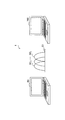
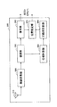
図1は、本発明の一実施形態に係る無線通信システム1について概略的に示した模式図である。図1を参照すると、無線通信システム1は、送信装置50と受信装置100とを含む。
FIG. 1 is a schematic diagram schematically showing a
図1では、送信装置50及び受信装置100としてPC(Personal Computer)を示しているが、送信装置50及び受信装置100はPCなどの情報処理装置に限られない。例えば、送信装置50又は受信装置100は、携帯電話端末やPDA(Personal Digital Assistants)、ゲーム端末などの端末装置、無線アクセスポイントやルータなどの通信専用装置、又はこれら装置に接続される無線通信モジュールなどであってもよい。
Although FIG. 1 shows a PC (Personal Computer) as the
送信装置50と受信装置100との間は、例えばOFDM(直交周波数分割多重:Orthogonal Frequency Division Multiplexing)方式に従った無線通信によって接続される。OFDM方式とは、直交する関係にある複数の周波数の副搬送波(Sub−Carrier)を並列的に用いて変調を行う変調方式であり、IEEE802.11a、g、nやワイヤレスUSBなどの標準仕様に採用されている。
For example, the
図1の例において、送信装置50と受信装置100との間に、搬送波C1が示されている。そして、搬送波C1には、周波数の異なる複数の副搬送波SC1〜SCiが多重化されている。受信装置100は、このような搬送波C1を用いて伝送される無線信号を受信し、送信装置50の位置を推定する。
In the example of FIG. 1, a carrier wave C <b> 1 is shown between the
なお、送信装置50と受信装置100との間の無線通信方式はOFDM方式に限定されない。本明細書にて説明する各実施形態は、周波数の異なる複数の副搬送波を用いるマルチキャリア方式の無線通信に一般的に適用され得る。
Note that the wireless communication scheme between the
〔2〕第1の実施形態(位相差平均と位相勾配を用いた位置推定の一例)
次に、図2〜図13を参照しながら、本発明の第1の実施形態について説明する。
[2] First embodiment (an example of position estimation using phase difference average and phase gradient)
Next, a first embodiment of the present invention will be described with reference to FIGS.
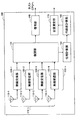
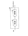
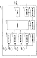
図2は、第1の実施形態に係る受信装置100の論理的な構成を示したブロック図である。図2を参照すると、受信装置100は、4本の受信アンテナ110−n(n=1〜4)、4つの無線受信部120−n(n=1〜4)、復調部130、復号部140、位相計算部150、行路差計算部160、及び位置推定部170を備える。
FIG. 2 is a block diagram illustrating a logical configuration of the receiving
受信アンテナ110−nは、それぞれ対応する無線受信部120−nと接続され、4つの受信ブランチを形成する。無線受信部120−nは、並列的に復調部130と接続される。復調部130は、復号部140及び位相計算部150に接続される。位相計算部150は、行路差計算部160と接続される。行路差計算部160は、位置推定部170と接続される。そして、復号部140及び位置推定部170は、例えばそれぞれホストCPU(Central Processing Unit)と接続される。
The reception antennas 110-n are connected to the corresponding radio reception units 120-n to form four reception branches. The radio reception unit 120-n is connected to the
受信アンテナ110−nは、送信装置50から送信された無線信号をそれぞれ受信し、受信した無線信号を同一の受信ブランチの無線受信部120−nへ出力する。
The reception antenna 110-n receives the radio signal transmitted from the
無線受信部120−nは、同一の受信ブランチの受信アンテナ110−nから出力された無線信号に対し、周波数変換やフィルタリング等の処理を行う。 The radio reception unit 120-n performs processing such as frequency conversion and filtering on the radio signal output from the reception antenna 110-n of the same reception branch.
図3は、無線受信部120−nの詳細な構成を示すブロック図である。図3を参照すると、無線受信部120−nは、RF回路122−n、AD(アナログ−デジタル)変換器124−n、フィルタ126−n、及びインバランス補正部128−nをそれぞれ含む。 FIG. 3 is a block diagram illustrating a detailed configuration of the wireless reception unit 120-n. Referring to FIG. 3, the wireless reception unit 120-n includes an RF circuit 122-n, an AD (analog-digital) converter 124-n, a filter 126-n, and an imbalance correction unit 128-n.
受信アンテナ110−nから出力された無線信号は、まずRF回路122−nにおいて増幅及び周波数変換される。RF回路122−nから出力されたアナログ信号は、AD変換器124−nによってデジタル信号に変換される。AD変換器124−nによってデジタル信号に変換された受信信号は、フィルタ126−nによってフィルタリング処理される。その後、フィルタ126−nから出力された信号は、インバランス補正部128−nによってIQインバランスの影響が除去され、復調部130へ入力される。
The radio signal output from the receiving antenna 110-n is first amplified and frequency-converted in the RF circuit 122-n. The analog signal output from the RF circuit 122-n is converted into a digital signal by the AD converter 124-n. The received signal converted into the digital signal by the AD converter 124-n is filtered by the filter 126-n. Thereafter, the signal output from the filter 126-n is removed from the influence of IQ imbalance by the imbalance correction unit 128-n and input to the
図2に戻り、受信装置100の説明を継続する。復調部130は、4本の受信ブランチからそれぞれ入力された受信信号を復調する。
Returning to FIG. 2, the description of the receiving
図4は、復調部130の詳細な構成を示すブロック図である。図4を参照すると、復調部130は、同期回路132、FFT(高速フーリエ変換:Fast Fourier Transform)回路134−n、チャネル推定部136−n、及び合成部138を含む。
FIG. 4 is a block diagram illustrating a detailed configuration of the
同期回路132は、4本の受信ブランチから入力された受信信号からパケットを検出し、同期タイミングと周波数オフセットとを測定した後、各受信信号からOFDMシンボルを切り出して、対応するFFT回路134−nへ出力する。同期回路132から出力されたOFDMシンボルは、FFT回路134−nによって高速フーリエ変換され、副搬送波ごとに分離される。FFT回路134−nによって副搬送波ごとに分離された受信信号は、チャネル推定部136−nにおけるチャネル推定結果に基づいて決定された信号合成比に従って、合成部138により合成される。そして、合成部138により合成された信号は、復調済みのストリーム信号として、復号部140へ出力される。
The
また、FFT部134−nにより副搬送波ごとに分離された受信信号は、チャネル推定部136−nへ入力されるのと並行して、位相計算部150へ入力される。位相計算部150における処理については、後に詳しく説明する。
In addition, the received signal separated for each subcarrier by the FFT unit 134-n is input to the
図2に戻り、受信装置100の説明を継続する。復号部140は、前述のように復調部130から入力された復調済みのストリーム信号を復号する。
Returning to FIG. 2, the description of the receiving
図5は、復号部140の詳細な構成を示すブロック図である。図5を参照すると、復号部140は、等化器142及び復号器144を含む。
FIG. 5 is a block diagram illustrating a detailed configuration of the
復号部140へ入力された復調済みのストリーム信号は、等化器142によってデジタル復調された後、復号器144によって復号される。復号されたデータ信号は、ホストCPUへ出力される。
The demodulated stream signal input to the
図6は、本実施形態において送信装置50から受信装置100へ送信される可能性のある無線信号に含まれるパケットの構成の一例を示している。
FIG. 6 illustrates an example of a configuration of a packet included in a radio signal that may be transmitted from the
図6(A)は、OFDM方式を採用したIEEE802.11nの通信仕様において規定されているパケットP1の構成の一例である。 FIG. 6A shows an example of the configuration of the packet P1 defined in the IEEE802.11n communication specification employing the OFDM method.
図6(A)を参照すると、パケットP1は、L−STF(Legacy−Short Training Field)、L−LTF(Legacy−Long Training Field)、L−SIG(Legacy−SIGnal field)、HT−SIG(High Throughput−SIG)、HT−STF、HT−LTF、及びData(データ部)の各フィールドを含む。 Referring to FIG. 6A, a packet P1 includes an L-STF (Legacy-Short Training Field), an L-LTF (Legacy-Long Training Field), an L-SIG (Legacy-Signal Field), and an HT-SIG (i.e. Throughput-SIG), HT-STF, HT-LTF, and Data (data part) fields are included.
このうち、L−STFは、例えば前述の同期回路132によるパケットを検出に用いられる。L−LTFは、例えば同期回路132による周波数オフセットの測定やチャネル推定部136−nによるチャネル推定に用いられる。L−SIGやHT−SIGには、例えばデータ長や通信レート、変調方式などの制御情報が含まれる。HT−STFは例えば利得調整に、HT−LTFはMIMO(Multiple Input Multiple Output)チャネル行列の取得に用いられる。データ部には、データシンボルが含まれる。
Among these, the L-STF is used for detecting a packet by the above-described
一方、図6(B)は、OFDM方式を採用したIEEE802.11aの通信仕様において規定されているパケットP2の構成の一例である。図6(B)を参照すると、パケットP2は、STF、LTF、SIG、及びDataの各フィールドを含む。 On the other hand, FIG. 6B is an example of the configuration of the packet P2 defined in the IEEE802.11a communication specification adopting the OFDM method. Referring to FIG. 6B, packet P2 includes STF, LTF, SIG, and Data fields.
ここで、例えば1つの送信アンテナから送信された1つの無線信号を複数の受信アンテナ110−nを用いて受信する場合、受信アンテナ110−nの位置に応じて無線信号が通信経路上を伝送される行路長には差異が生じる。 Here, for example, when one radio signal transmitted from one transmission antenna is received using the plurality of reception antennas 110-n, the radio signal is transmitted on the communication path according to the position of the reception antenna 110-n. There is a difference in the route length.
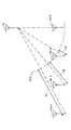
図7は、そのような受信アンテナ110−nの位置に応じた無線信号の行路長の差異を、概念的に示した説明図である。図7を参照すると、送信アンテナTxから受信アンテナ110−1、110−2、110−3及び110−4までの無線信号の行路が示されている。 FIG. 7 is an explanatory diagram conceptually showing the difference in the path length of the radio signal according to the position of the receiving antenna 110-n. Referring to FIG. 7, a path of a radio signal from the transmission antenna Tx to the reception antennas 110-1, 110-2, 110-3, and 110-4 is shown.
図7において、弧STDは、送信アンテナTxとの間に、送信アンテナTxから受信アンテナ110−4までの無線信号の行路長と等しい距離を有する位置の軌跡を示している。 In FIG. 7, an arc STD indicates a locus of a position having a distance equal to the path length of the radio signal from the transmission antenna Tx to the reception antenna 110-4 between the transmission antenna Tx.
この受信アンテナ110−4までの行路長を基準とすると、送信アンテナTxから受信アンテナ110−1までの行路長は距離d1だけ長い。また、送信アンテナTxから受信アンテナ110−2までの行路長は距離d2、送信アンテナTxから受信アンテナ110−3までの行路長は距離d3だけ長いことが分かる。本明細書では、このような受信アンテナ間の行路長の差、即ち、例えば距離d1、d2、d3などを、行路差と称する。 Based on the path length to the receiving antenna 110-4, the path length from the transmitting antenna Tx to the receiving antenna 110-1 is longer by the distance d1. It can also be seen that the path length from the transmission antenna Tx to the reception antenna 110-2 is longer by the distance d2, and the path length from the transmission antenna Tx to the reception antenna 110-3 is longer by the distance d3. In this specification, such differences in path length between receiving antennas, that is, distances d1, d2, d3, for example, are referred to as path differences.
このように受信アンテナ110−nの間で行路差dが存在した場合、受信アンテナ110−nによって受信される無線信号の位相にずれが生じる。受信アンテナ110−nによって受信される無線信号の位相のずれ、即ち受信アンテナ110−n間の位相差φと行路差dの関係は、次式で表される。 When there is a path difference d between the receiving antennas 110-n as described above, a phase shift occurs in the radio signal received by the receiving antenna 110-n. The phase shift of the radio signal received by the receiving antenna 110-n, that is, the relationship between the phase difference φ between the receiving antennas 110-n and the path difference d is expressed by the following equation.

ここで、λは無線信号の波長、mは行路差dの間に位相が何周したかを示す整数である。 Here, λ is the wavelength of the radio signal, and m is an integer indicating how many times the phase has rotated during the path difference d.
式(1)によれば、行路差dが一定であった場合には、位相差φは、無線信号の波長λに依存する。よって、無線信号として周波数の異なる副搬送波が多重化された例えばOFDM方式の無線信号を用いた場合には、同一の受信アンテナ110−nであっても、当該受信アンテナ110−nにより受信された無線信号の副搬送波ごとに、検知される位相が異なる。 According to Expression (1), when the path difference d is constant, the phase difference φ depends on the wavelength λ of the radio signal. Therefore, when, for example, an OFDM radio signal in which sub-carriers having different frequencies are multiplexed is used as a radio signal, the same reception antenna 110-n is received by the reception antenna 110-n. The detected phase differs for each subcarrier of the radio signal.
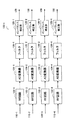
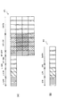
図8は、同一の受信アンテナ110−nにおける副搬送波ごとの位相差を概念的に示した説明図である。 FIG. 8 is an explanatory diagram conceptually showing the phase difference for each subcarrier in the same receiving antenna 110-n.
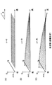
図8(A)〜(C)のうち、図8(A)は、基準となるアンテナとの間の行路差dがd=0である場合の、副搬送波ごとの位相差を示している。これに対し、図8(B)は行路差dが中程度の場合、図8(C)は行路差dが大きい場合の副搬送波ごとの位相差を示している。 8A to 8C, FIG. 8A shows the phase difference for each subcarrier when the path difference d from the reference antenna is d = 0. On the other hand, FIG. 8B shows the phase difference for each subcarrier when the path difference d is medium, and FIG. 8C shows the phase difference for each subcarrier when the path difference d is large.
図8(A)〜(C)に示した多数の小さい矢印は、無線信号に含まれる各副搬送波を表す。各図の横軸は、副搬送波の周波数に対応する。即ち、図中右側に示した矢印は、図中左側に示した矢印よりも高い周波数の(即ち、波長が短い)副搬送波に対応する。また、横軸に対する矢印の回転角は、対応する副搬送波について検知される位相差φを表す。 A number of small arrows shown in FIGS. 8A to 8C represent each subcarrier included in the radio signal. The horizontal axis in each figure corresponds to the frequency of the subcarrier. That is, the arrow shown on the right side in the figure corresponds to a subcarrier having a higher frequency (that is, a shorter wavelength) than the arrow shown on the left side in the figure. The rotation angle of the arrow with respect to the horizontal axis represents the phase difference φ detected for the corresponding subcarrier.
図8(A)を参照すると、行路差d=0の場合、位相差φは副搬送波の周波数によらず一定である。一方、図8(B)の例では、副搬送波間の位相差の平均を矢印AVGとすると、周波数の低い副搬送波では位相差φは矢印AVGよりも大きく、周波数の高い副搬送波では位相差φは矢印AVGよりも小さい。このような位相のねじれは、周波数の所定の変化量に対する位相の変化量として定量化することができる。本明細書では、このような位相の変化量を、位相勾配と称する。行路差dがより大きい図8(C)の例では、位相のねじれはさらに大きくなっている。 Referring to FIG. 8A, when the path difference d = 0, the phase difference φ is constant regardless of the subcarrier frequency. On the other hand, in the example of FIG. 8B, if the average of the phase difference between the subcarriers is an arrow AVG, the phase difference φ is larger than that of the arrow AVG for the subcarrier having a low frequency and the phase difference φ is for a subcarrier having a high frequency. Is smaller than the arrow AVG. Such a phase twist can be quantified as a change in phase with respect to a predetermined change in frequency. In the present specification, such a phase change amount is referred to as a phase gradient. In the example of FIG. 8C in which the path difference d is larger, the phase twist is further increased.
一例として、IEEE802.11nの標準仕様の40MHzモードにおいて、無線信号の周波数帯の中央周波数をfmid=5[GHz]、下端周波数fbtm=4.98[GHz]、上端周波数ftop=5.02[GHz]とする。そうすると、中央周波数に対する波長λmid=6.00[cm]、下端周波数に対する波長λbtm=6.024[cm]、上端周波数に対する波長λtop=5.976[cm]となる。 As an example, in the IEEE 802.11n standard 40 MHz mode, the center frequency of the radio signal frequency band is f mid = 5 [GHz], the lower end frequency f btm = 4.98 [GHz], and the upper end frequency f top = 5. 02 [GHz]. Then, the wavelength λ mid = 6.00 [cm] for the central frequency, the wavelength λ btm = 6.024 [cm] for the lower end frequency, and the wavelength λ top = 5.976 [cm] for the upper end frequency.
ここで、行路差d=6[cm]であったとする。その場合、中央周波数において位相差φmid=2πであり、即ち1つの周波数帯内の全副搬送波の位相差平均φAVG=2πとなる。一方、下端周波数における位相差φbtm=2π×(6.00/6.024)、上端周波数における位相差φtop=2π×(6.00/5.976)である。よって、周波数帯の両端の間の位相のねじれφtop−φbtm=約2.88[deg]となる。 Here, it is assumed that the path difference d = 6 [cm]. In that case, the phase difference φ mid = 2π at the center frequency, that is, the average phase difference φ AVG = 2π of all subcarriers in one frequency band. On the other hand, the phase difference φ btm = 2π × (6.00 / 6.024) at the lower end frequency and the phase difference φ top = 2π × (6.00 / 5.976) at the upper end frequency. Therefore, the phase twist between both ends of the frequency band is φ top −φ btm = about 2.88 [deg].
受信アンテナ110−n間の位相差平均φAVG、及び受信アンテナ110−nにおける位相勾配θと、受信アンテナ110−n間の行路差dとの関係についてさらに説明する。 The relationship between the phase difference average φ AVG between the receiving antennas 110-n and the phase gradient θ in the receiving antenna 110-n and the path difference d between the receiving antennas 110-n will be further described.
離散フーリエ変換の等式から、信号xnと1サンプル推移した信号xn+1との間の関係は、次式で表される。 From equation of the discrete Fourier transform, the relationship between the signal x n + 1 which remained signal x n and one sample is expressed by the following equation.
![]()
![]()
![]()
![]()
![]()
![]()
即ち、1周波数帯内の全ての副搬送波にわたって、1周分(360°)に相当する位相のねじれが生じる。40[MHz]の周波数帯の両端の間のねじれに相当する行路差は、3×10⁸[m]/40[MHz]=7.5[m]である。よって、行路差d=7.5[m]で位相のねじれが1周分に達する。行路差d=6[cm]では、2.88[deg]に相当する。 That is, a phase twist corresponding to one round (360 °) occurs over all subcarriers in one frequency band. The path difference corresponding to the twist between both ends of the 40 [MHz] frequency band is 3 × 10 8 [m] / 40 [MHz] = 7.5 [m]. Therefore, the twist of the phase reaches one round at the path difference d = 7.5 [m]. The path difference d = 6 [cm] corresponds to 2.88 [deg].
ここで、仮に受信アンテナ110−n間の位相差平均φAVG=0[deg]であった場合には、行路差dは、0又は波長λの整数倍のいずれかの値となり、位相差平均φAVGの値だけでは行路差dは一意に定まらない。そこで、本実施形態では、以下の関係式に基づき、さらに位相勾配θを考慮して行路差dを決定する。 Here, if the phase difference average φ AVG between the receiving antennas 110-n is 0 [deg], the path difference d is either 0 or an integer multiple of the wavelength λ, and the phase difference average φ path difference is only the value of AVG d is uniquely determined. Therefore, in the present embodiment, the path difference d is determined in consideration of the phase gradient θ based on the following relational expression.
まず、中央周波数(キャリア周波数に相当)の波長λmidと任意の副搬送波の波長λsとの関係は、式(1)から次式のように導かれる。 First, the relationship between the wavelength λ mid of the center frequency (corresponding to the carrier frequency) and the wavelength λ s of an arbitrary subcarrier is derived from the equation (1) as follows:
ここで、δφは、中央周波数における位相と当該副搬送波における位相の間の位相差である。周波数軸上で隣り合う副搬送波間の位相差を位相勾配θと定義すると、位相差δφは次式で与えられる。 Here, δφ is a phase difference between the phase at the center frequency and the phase at the subcarrier. If the phase difference between adjacent subcarriers on the frequency axis is defined as a phase gradient θ, the phase difference δφ is given by the following equation.
![]()
![]()
ここで、Nは中央周波数から当該副搬送波の周波数までの間に存在する副搬送波の本数である。また、波長λmidと波長λsの関係は、中央周波数fmid及び副搬送波の周波数fsを用いて、次式で表される。 Here, N is the number of subcarriers existing between the center frequency and the frequency of the subcarrier. The relationship between the wavelength λ mid and the wavelength λ s is expressed by the following equation using the center frequency f mid and the subcarrier frequency f s .
式(5)、式(6)、式(8)より、次式が導かれる。 From the equations (5), (6), and (8), the following equation is derived.
さらに、当該副搬送波における位相のねじれの割合θλを次式のように定義する。 Further, the phase twist ratio θ λ in the subcarrier is defined as follows.
そうすると、式(9)及び式(10)から、行路差dと位相差φとの間の関係式(1)における整数mが、次式のように導かれる。 Then, the integer m in the relational expression (1) between the path difference d and the phase difference φ is derived from Expression (9) and Expression (10) as follows:
式(11)において、mを決定するパラメータのうち、θλは行路差dに依存しない。よって、受信アンテナ110−nの位置に応じて行路差dが変化した場合、受信アンテナ110−nごとの位相差平均φAVGと、δφを決定するための位相勾配θとを用いて、行路差dの間に位相が何周したかを表す整数mを決定できることが理解される。 Of the parameters that determine m in equation (11), θ λ does not depend on the path difference d. Therefore, when the path difference d changes according to the position of the receiving antenna 110-n, the path difference is calculated using the phase difference average φ AVG for each receiving antenna 110-n and the phase gradient θ for determining δφ. It will be appreciated that an integer m can be determined which represents how many phases the phase has d during d.
そして、整数mが決定されれば、さらに中央周波数における波長λmid及び位相差平均φAVGを用いて、受信アンテナ110−n間の行路差dを式(1)により計算することができる。 When the integer m is determined, the path difference d between the receiving antennas 110-n can be calculated by the equation (1) using the wavelength λ mid and the phase difference average φ AVG at the center frequency.
図2において、位相計算部150は、復調部130から入力される復調済みのストリーム信号を用いて、前述した受信アンテナ110−n間の行路差dの計算に必要とされる位相差平均φAVG及び位相勾配θを計算する。
In FIG. 2, the
図9は、位相計算部150の詳細な構成を示すブロック図である。図9を参照すると、位相計算部150は、複素共役計算部152、乗算器154−m(m=1、2、3)、平均計算部156−m、及び勾配計算部158−mを含む。
FIG. 9 is a block diagram illustrating a detailed configuration of the
図9の例では、位相計算部150は、受信アンテナ110−nのうち、受信アンテナ110−4により受信された無線信号に対応する入力信号を、位相差の計算の基準信号としている。そのため、受信アンテナ110−4により受信され復調されたストリーム信号S4は、複素共役計算部152に入力される。一方、受信アンテナ110−1、2、3により受信され復調されたストリーム信号S1、S2、S3は、それぞれ乗算器154−1、154−2、及び154−3に入力される。
In the example of FIG. 9, the
複素共役計算部152は、ストリーム信号S4の複素共役値を計算し、その結果得られた信号を乗算器154−1、154−2、及び154−3へ入力する。
Complex
乗算器154−1、154−2、及び154−3は、複素共役計算部152から入力されたストリーム信号S4の複素共役値とストリーム信号S1、S2、S3とをそれぞれ乗算する。その結果、ストリーム信号S1、S2、S3に含まれる副搬送波ごとの信号値について、それぞれ基準信号との間の位相差が計算される。
Multipliers 154-1 and 154-2, and 154-3 multiplies the complex conjugate value of the stream signal S 4 that is input from the complex
そして、平均計算部156−1は、乗算器154−1により計算されたストリーム信号S1の副搬送波ごとの位相差を用いて、受信アンテナ110−1についての位相差平均φAVG1を計算する。また、勾配計算部158−1は、当該位相差を用いて、受信アンテナ110−1についての位相勾配θ1を計算する。 The average calculation unit 156-1 uses the phase difference of each sub-carrier of the stream signals S 1 calculated by the multiplier 154-1, calculates the phase difference average phi AVG1 the receiving antenna 110-1. Further, the gradient calculation unit 158-1, by using the phase difference, compute the phase gradient theta 1 of the receive antenna 110-1.
同様に、平均計算部156−2は、受信アンテナ110−2についての位相差平均φAVG2を、勾配計算部158−2は、受信アンテナ110−2についての位相勾配θ2を計算する。さらに、平均計算部156−3は、受信アンテナ110−3についての位相差平均φAVG3を、勾配計算部158−3は、受信アンテナ110−3についての位相勾配θ3を計算する。 Similarly, the average calculation unit 156-2 is a phase difference average phi AVG2 the receiving antenna 110-2, the gradient calculation unit 158-2 calculates a phase gradient theta 2 of the receiving antenna 110-2. Further, the average calculation unit 156-3 calculates the phase difference average φ AVG3 for the reception antenna 110-3, and the gradient calculation unit 158-3 calculates the phase gradient θ 3 for the reception antenna 110-3.
これら処理の結果得られた位相差平均φAVG1及び位相勾配θ1、位相差平均φAVG2及び位相勾配θ2、並びに位相差平均φAVG3及び位相勾配θ3は、行路差計算部160へ出力される。
The phase difference average φ AVG1 and phase gradient θ 1 , phase difference average φ AVG2 and phase gradient θ 2 , and phase difference average φ AVG3 and phase gradient θ 3 obtained as a result of these processes are output to the path
なお、ここでは、位相差の計算の基準とする基準信号を受信アンテナ110−4により受信された信号とする例について説明した。しかしながら、基準信号は、いずれかの受信アンテナにより受信された信号、又は例えば予め与えられる既知の信号であってもよい。 Here, an example in which the reference signal used as the reference for calculating the phase difference is the signal received by the receiving antenna 110-4 has been described. However, the reference signal may be a signal received by any receiving antenna or a known signal given in advance.
図2において、行路差計算部160は、位相計算部150から入力される受信アンテナ110−nごとの位相差平均及び位相勾配を用いて、前述の式(1)〜式(11)に従い、無線信号が送信された送信アンテナから受信アンテナ110−nのうち任意の2つの受信アンテナまでの行路差を計算する。
In FIG. 2, the path
ここで、行路差計算部160による計算の結果、受信アンテナ110−1と受信アンテナ110−4の間の行路差d14が得られたとする。そうすると、無線信号が送信された送信アンテナの位置は、受信アンテナ110−1及び受信アンテナ110−4からの距離の差が一定(即ちd14)となる曲面上にあると考えることができる。
Here, the result of calculation by the path
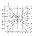
図10は、受信アンテナ110−1と受信アンテナ110−4を通る二次元平面上において、行路差d14から推定される送信アンテナの位置を示した説明図である。 10, in the two-dimensional plane in which the receiving antenna 110-1 through the reception antenna 110-4 is an explanatory view showing the position of the transmitting antennas to be estimated from the path difference d 14.
図10において、原点を通る水平軸上の座標(−1、0)、(1、0)に、受信アンテナ110−1と受信アンテナ110−4がそれぞれ位置している。 In FIG. 10, the receiving antenna 110-1 and the receiving antenna 110-4 are located at coordinates (−1, 0) and (1, 0) on the horizontal axis passing through the origin.
受信アンテナ110−1と受信アンテナ110−4の間の行路差d14がd14=0となる場合、送信アンテナは、受信アンテナ110−1と受信アンテナ110−4の中間点を通る直線L0上に位置する。 When the path difference d 14 between the receiving antenna 110-1 and the receiving antenna 110-4 is d 14 = 0, the transmitting antenna is on a straight line L0 passing through an intermediate point between the receiving antenna 110-1 and the receiving antenna 110-4. Located in.
また、行路差d14≠0の場合、送信アンテナの位置の描く軌跡は、論理的には双曲線を描く。そして、その双曲線の焦点に、受信アンテナ110−1及び受信アンテナ110−4が位置する。 When the path difference d 14 ≠ 0, the locus drawn by the position of the transmitting antenna logically draws a hyperbola. The receiving antenna 110-1 and the receiving antenna 110-4 are located at the focal point of the hyperbola.
例えば、行路差d14が受信アンテナ110−1と受信アンテナ110−4の間隔の20%であれば、送信アンテナは、双曲線L1又はL6上に位置する。このうち、受信アンテナ110−1の位相が受信アンテナ110−4に対して進んでいるか遅れているかを判定することによって、送信アンテナが双曲線L1とL6のいずれに位置するかを決定することができる。 For example, if 20% of the path difference d 14 is the receiving antenna 110-1 and spacing of the receiving antennas 110-4, the transmitting antenna is located on the hyperbola L1 or L6. Of these, by determining whether the phase of the receiving antenna 110-1 is advanced or delayed with respect to the receiving antenna 110-4, it is possible to determine whether the transmitting antenna is located on the hyperbola L1 or L6. .
同様に、行路差d14が受信アンテナ110−1と受信アンテナ110−4の間隔の40%であれば、送信アンテナは、双曲線L2又はL7上に位置する。行路差d14が受信アンテナ110−1と受信アンテナ110−4の間隔の60%であれば、送信アンテナは、双曲線L3又はL8上に位置する。さらに、行路差d14が受信アンテナ110−1と受信アンテナ110−4の間隔の80%であれば、送信アンテナは、双曲線L4又はL9上に位置する。 Similarly, if 40% of the path difference d 14 is the receiving antenna 110-1 and spacing of the receiving antennas 110-4, the transmitting antenna is located on the hyperbola L2 or L7. If the path difference d 14 is 60% of the distance between the receiving antennas 110-1 receive antenna 110-4, the transmitting antenna is located on the hyperbola L3 or L8. Further, if 80% of the path difference d 14 is the receiving antenna 110-1 and spacing of the receiving antennas 110-4, the transmitting antenna is located on the hyperbola L4 or L9.
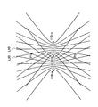
図11は、受信アンテナ110−nのうち、受信アンテナ110−aと110−bの間の行路差、及び受信アンテナ110−bと110−cの間の行路差に基づいて、送信アンテナの位置を推定する一例について説明するための説明図である。 FIG. 11 shows the position of the transmitting antenna based on the path difference between the receiving antennas 110-a and 110-b and the path difference between the receiving antennas 110-b and 110-c among the receiving antennas 110-n. It is explanatory drawing for demonstrating an example which estimates this.
図11において、受信アンテナ110−aと110−bの間の行路差に基づき、例えば曲線L10上に送信アンテナが位置していると推定されたとする。また、受信アンテナ110−bと110−cの間の行路差に基づき、例えば曲線L20上に送信アンテナが位置していると推定されたとする。そうすると、送信アンテナは、曲線L10及び曲線L20の交点P1又はP2上に位置すると推定される。 In FIG. 11, it is assumed that, for example, it is estimated that the transmission antenna is located on the curve L10 based on the path difference between the reception antennas 110-a and 110-b. Further, based on the path difference between the receiving antennas 110-b and 110-c, for example, it is assumed that the transmitting antenna is located on the curve L20. Then, the transmission antenna is estimated to be located on the intersection P1 or P2 of the curve L10 and the curve L20.
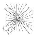
図12は、受信アンテナ110−aと110−bの間の行路差、及び受信アンテナ110bと110−cの間の行路差に基づいて、送信アンテナの位置を推定する他の例について説明するための説明図である。 FIG. 12 illustrates another example of estimating the position of the transmitting antenna based on the path difference between the receiving antennas 110-a and 110-b and the path difference between the receiving antennas 110b and 110-c. It is explanatory drawing of.
図12において、受信アンテナ110−aと110−bの間の行路差に基づき、例えば曲線L30上に送信アンテナが位置していると推定されたとする。また、受信アンテナ110−bと110−cの間の行路差に基づき、例えば曲線L40上に送信アンテナが位置していると推定されたとする。そうすると、送信アンテナは、曲線L30及びL40の交点P3上に位置すると推定される。 In FIG. 12, suppose that it is estimated that the transmitting antenna is located on the curve L30, for example, based on the path difference between the receiving antennas 110-a and 110-b. Further, based on the path difference between the receiving antennas 110-b and 110-c, for example, it is assumed that the transmitting antenna is located on the curve L40. Then, it is estimated that the transmission antenna is located on the intersection P3 of the curves L30 and L40.
図11及び図12を用いて説明したように、受信アンテナ110−nのうち2組の受信アンテナについてそれぞれ計算された行路差を用いることで、二次元平面上の送信アンテナの位置を推定することができる。また、こうした考え方を拡張し、受信アンテナ110−nのうち3組以上の受信アンテナについてそれぞれ計算された行路差を用いることで、三次元空間内の送信アンテナの位置を推定できることが理解される。 As described with reference to FIGS. 11 and 12, the position of the transmitting antenna on the two-dimensional plane is estimated by using the path difference calculated for each of the two sets of receiving antennas 110-n. Can do. Further, it is understood that the position of the transmission antenna in the three-dimensional space can be estimated by extending such a concept and using the path differences calculated for each of three or more sets of reception antennas 110-n.
図2において、位置推定部170は、このようにして、行路差計算部160によって2組以上の受信アンテナ110−nについて計算された行路差を用いて、無線信号が送信された送信アンテナの位置を推定する。
In FIG. 2, the
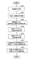
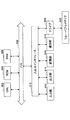
図13は、本実施形態に係る受信装置100による送信アンテナの位置推定処理の流れの一例を示すフローチャートである。
FIG. 13 is a flowchart illustrating an example of the flow of the position estimation process of the transmission antenna by the
図13を参照すると、まず、周波数の異なる副搬送波が多重化された無線信号を、複数の受信アンテナ110−nがそれぞれ受信する(S502)。 Referring to FIG. 13, first, a plurality of receiving antennas 110-n respectively receive radio signals in which subcarriers having different frequencies are multiplexed (S502).
次に、無線受信部120−nによりデジタル信号に変換された受信信号が復調部130により復調され、副搬送波ごとの信号にそれぞれ分離される(S504)。
Next, the reception signal converted into the digital signal by the radio reception unit 120-n is demodulated by the
そして、副搬送波ごとに分離されたそれぞれの信号について、位相計算部150により基準信号との間の位相差が計算される(S506)。ここで、位相計算部150は、例えば受信アンテナ110−nのうちの1つの受信アンテナにより受信された信号を基準信号とし、当該基準信号の複素共役値と副搬送波ごとの信号値とを乗算し、副搬送波ごとの位相差を計算する。このとき、基準信号は、1つの受信アンテナにより受信された信号ではなく、予め与えられる既知の信号であってもよい。
Then, for each signal separated for each subcarrier, the phase difference between the
その後、位相計算部150は、副搬送波ごとに計算した位相差を用いて、受信アンテナ110−nごとに位相差平均を計算する(S508)。また、位相計算部150は、副搬送波ごとに計算した位相差を用いて、受信アンテナ110−nごとに位相勾配を計算する(S510)。
Thereafter, the
そして、行路差計算部160は、位相計算部150により計算された受信アンテナごとの位相差平均と位相勾配とに基づいて、無線信号が送信された送信アンテナから受信アンテナ110−nのうち任意の2つの受信アンテナまでの行路差を計算する(S512)。
Then, the path
さらに、行路差計算部160によって2組以上の受信アンテナについて計算された行路差を用いて、位置推定部170により送信アンテナの位置が推定される(S514)。
Further, the
ここまで、図2〜図13を用いて、本発明の第1の実施形態に係る受信装置100について説明を行った。本実施形態によれば、周波数の異なる副搬送波が多重化された無線信号を複数の受信アンテナで受信し、各無線信号に含まれる副搬送波ごとに計算された位相差に基づいて、送信アンテナから任意の2つの受信アンテナまでの行路差が計算される。それにより、例えば信号の折り返し時間の保証などの追加的な要件を通信相手に求めることなく、無線信号を用いた位置の推定の精度を向上させることができる。
Up to this point, the receiving
このとき、副搬送波ごとの位相差を、例えば基準信号の複素共役値と副搬送波ごとの信号値との乗算により計算してもよい。また、送信アンテナから2つの受信アンテナまでの行路差を、受信アンテナごとの位相差平均と位相勾配とに基づいて計算してもよい。そうした場合には、受信アンテナ間の行路差の計算を、比較的小さい計算コストにより行うことができる。 At this time, the phase difference for each subcarrier may be calculated by, for example, multiplying the complex conjugate value of the reference signal by the signal value for each subcarrier. Further, the path difference from the transmitting antenna to the two receiving antennas may be calculated based on the average phase difference and the phase gradient for each receiving antenna. In such a case, the path difference between the receiving antennas can be calculated at a relatively low calculation cost.
また、行路差の計算を、任意の2組以上の受信アンテナについて行ってもよい。例えば、2組の受信アンテナについて行路差を計算することにより、二次元平面上での通信相手の位置を推定することができる。また、3組以上の受信アンテナについて行路差を計算することにより、三次元空間内での通信相手の位置を推定することができる。 Further, the path difference may be calculated for any two or more sets of receiving antennas. For example, the position of the communication partner on the two-dimensional plane can be estimated by calculating the path difference for two sets of receiving antennas. In addition, the position of the communication partner in the three-dimensional space can be estimated by calculating the path difference for three or more sets of receiving antennas.
また、副搬送波ごとの位相差の基準となる基準信号として、複数の受信アンテナのうちの1つの受信アンテナにより受信される無線信号を用いてもよい。かかる場合には、同一の通信環境を経て届いた無線信号間で位相差が計算されるため、通信環境が信号に与える影響が相互に打ち消され、位置推定の精度が向上され得る。 In addition, a radio signal received by one receiving antenna among a plurality of receiving antennas may be used as a reference signal serving as a reference for the phase difference for each subcarrier. In such a case, since the phase difference is calculated between the radio signals that have arrived through the same communication environment, the influence of the communication environment on the signal is canceled out and the accuracy of position estimation can be improved.
なお、本実施形態では、送信アンテナから受信アンテナ110−nまでの行路差を位相差平均と位相勾配とを用いて計算した。しかしながら、その代わりに、例えばMUSIC(MUltiple SIgnal Classification)法、ESPRIT(Estimation of Signal Parameters via Rotational Invariance Techniques)法などの部分空間法を用いて、受信アンテナ110−nまでの行路差を計算してもよい。 In the present embodiment, the path difference from the transmitting antenna to the receiving antenna 110-n is calculated using the phase difference average and the phase gradient. However, instead of using the subspace method such as the MUSIC (Multiple Signal Classification) method or the ESPRIT (Estimation of Signal Parameters via Rotational Invariance Techniques) method to the reception antenna 110n difference calculation. Good.
また、前述した位相計算部150による位相差の計算処理を1つの無線信号について複数回実行し、その結果得られた複数の位相差に基づいて受信アンテナ間の行路差を計算してもよい。例えば、同一の副搬送波について複数回計算した位相差の平均値や中央値に基づいて行路差を計算することにより、行路差の計算結果に含まれる誤差を低減させることができる。
Further, the above-described phase difference calculation processing by the
〔3〕第2の実施形態(複数の周波数チャネルを使用する一例)
本発明の第1の実施形態では、周波数の異なる副搬送波が多重化された1つの周波数チャネルの無線信号を複数のアンテナで受信して送信アンテナの位置を推定する受信装置100について説明した。例えば、図8に関連する説明においては、中央周波数fmidを5[GHz]とするIEEE802.11nの1つの周波数チャネルを例に挙げて行路差と位相差平均、位相勾配との関係について述べた。
[3] Second embodiment (an example using a plurality of frequency channels)
In the first embodiment of the present invention, the receiving
ここで、各副搬送波のアンテナ間の位相差や位相勾配は周波数チャネルの帯域幅が広い方がより明確に現れる。また、計算される行路差の精度は搬送波の波長が短いほど高くなり、位相差は搬送波の波長が長いほど行路差に対して緩やかに現れる。そこで、本発明の第2の実施形態に係る受信装置200では、周波数チャネルを複数の周波数帯に変えながら位相差を計算し、位置推定処理の精度を向上させる。
Here, the phase difference or phase gradient between the antennas of each subcarrier appears more clearly when the frequency channel bandwidth is wider. Further, the accuracy of the calculated path difference becomes higher as the wavelength of the carrier wave becomes shorter, and the phase difference appears more gradually with respect to the path difference as the wavelength of the carrier wave becomes longer. Therefore, the receiving
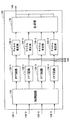
図14は、第2の実施形態に係る受信装置200の論理的な構成を示したブロック図である。図14を参照すると、受信装置200は、4本の受信アンテナ110−n、4つの無線受信部120−n、復調部130、復号部140、位相計算部150、行路差計算部260、位置推定部170、及び周波数制御部280を備える。
FIG. 14 is a block diagram showing a logical configuration of the receiving
周波数制御部280は、無線受信部120−nに周波数制御信号を出力することにより、受信アンテナ110−nにより受信される無線信号の周波数帯を制御する。そして、受信アンテナ110−nは、周波数制御部280による制御に応じて、例えば周波数の異なる副搬送波がそれぞれ多重化された第1の周波数帯の無線信号と第2の周波数帯の無線信号とを受信する。第1及び第2の周波数帯の無線信号とは、例えば中央周波数fmid=5.00[GHz]の周波数チャネル及び中央周波数fmid=5.08[GHz]の周波数チャネルの無線信号であってもよい。
The
受信アンテナ110−nにより第1の周波数帯の無線信号が受信されると、第1の実施形態に関連して説明した処理に従って、受信アンテナ110−nごとに第1の周波数帯の無線信号についての第1の位相勾配が、位相計算部150により計算される。また、受信アンテナ110−nにより第2の周波数帯の無線信号が受信されると、同様に、第2の周波数帯の無線信号についての第2の位相勾配が、位相計算部150により計算される。
When a radio signal in the first frequency band is received by the reception antenna 110-n, the radio signal in the first frequency band is received for each reception antenna 110-n according to the process described in relation to the first embodiment. The first phase gradient is calculated by the
そして、行路差計算部260は、例えば第1の位相勾配と第2の位相勾配の平均を計算して位相勾配の誤差を低減した上で、受信アンテナ110−n間の行路差を計算する。また、その代わりに、行路差計算部260は、例えば式(1)の整数mを式(11)を用いて決定する際に、第1の位相差平均と第2の位相差平均から計算した新たな位相勾配をさらに用いて整数mを決定し、それにより行路差計算の精度を高めてもよい。
The path
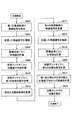
図15は、本実施形態に係る受信装置200による送信アンテナの位置推定処理の流れの一例を示すフローチャートである。
FIG. 15 is a flowchart illustrating an example of the flow of the position estimation process of the transmission antenna by the
図15を参照すると、まず、第1の周波数帯において、周波数の異なる副搬送波が多重化された無線信号を、複数の受信アンテナ110−nが受信する(S602)。 Referring to FIG. 15, first, a plurality of receiving antennas 110-n receive a radio signal in which subcarriers having different frequencies are multiplexed in the first frequency band (S602).
次に、無線受信部120−nによりデジタル信号に変換された受信信号が復調部130により復調され、副搬送波ごとの信号にそれぞれ分離される(S604)。
Next, the reception signal converted into the digital signal by the radio reception unit 120-n is demodulated by the
そして、副搬送波ごとに分離されたそれぞれの信号について、位相計算部150により基準信号との間の位相差が計算される(S606)。
Then, for each signal separated for each subcarrier, the phase difference between the
その後、位相計算部150は、副搬送波ごとに計算した位相差を用いて、受信アンテナ110−nごとに位相差平均を計算する(S608)。また、位相計算部150は、副搬送波ごとに計算した位相差を用いて、受信アンテナ110−nごとに第1の位相勾配を計算する(S610)。
Thereafter, the
位相計算部150による位相差平均と位相勾配の計算が終了した後、周波数制御部280は、無線受信部120−nに周波数制御信号を出力し、受信アンテナ110−nにより受信される無線信号の周波数帯を第1の周波数帯から第2の周波数帯へ変更する(S612)。
After the calculation of the phase difference average and the phase gradient by the
それにより、第2の周波数帯において、周波数の異なる副搬送波が多重化された無線信号が複数の受信アンテナ110−nにより受信され(S614)、復調部130により復調され(S616)、位相計算部150により基準信号との間の位相差が計算される(S618)。 As a result, in the second frequency band, radio signals in which subcarriers having different frequencies are multiplexed are received by the plurality of receiving antennas 110-n (S614), demodulated by the demodulator 130 (S616), and the phase calculator The phase difference from the reference signal is calculated by 150 (S618).
そして、位相計算部150は、副搬送波ごとに計算した位相差を用いて、受信アンテナ110−nごとに第2の位相勾配を計算する(S620)。
Then, the
そして、行路差計算部260は、位相計算部150により計算された受信アンテナごとの位相差平均と第1及び第2の位相勾配とに基づいて、送信アンテナから任意の2つの受信アンテナまでの行路差を計算する(S622)。
Then, the path
さらに、行路差計算部260により2組以上の受信アンテナについて計算された行路差を用いて、位置推定部170により送信アンテナの位置が推定される(S624)。
Further, using the calculated path differences for two or more pairs of receiving antennas by the path
ここまで、図14及び図15を用いて、本発明の第2の実施形態に係る受信装置200について説明を行った。本実施形態によれば、2つ以上の異なる周波数帯で受信した無線信号について、副搬送波ごとの位相勾配が計算される。それにより、位相勾配に基づいて計算される行路差の誤差が低減され、位置推定の精度が向上される。
Up to this point, the
なお、本実施形態では、第1の周波数帯で計算した第1の位相勾配と第2の周波数帯で計算した第2の位相勾配とに基づいて送信アンテナからの行路差を計算する例について説明した。しかしながら、その代わりに、隣り合う第1の周波数帯と第2の周波数帯を帯域幅を広げられた仮想的な1つの周波数帯とみなし、その1つの周波数帯について副搬送波ごとの位相差から1つの位相勾配を計算してもよい。例えば、第1の周波数帯と第2の周波数帯が共に40MHzの帯域幅を有していた場合には、それぞれ計算した副搬送波ごとの位相差に基づいて、80MHzの帯域幅を持つ仮想的な周波数帯について1つの位相勾配を計算することができる。その場合にも、位相勾配に基づいて計算される行路差の誤差が低減され、位置推定の精度が向上される。 In this embodiment, an example is described in which the path difference from the transmission antenna is calculated based on the first phase gradient calculated in the first frequency band and the second phase gradient calculated in the second frequency band. did. However, instead, the adjacent first frequency band and second frequency band are regarded as one virtual frequency band with an expanded bandwidth, and the one frequency band is calculated from the phase difference for each subcarrier. Two phase gradients may be calculated. For example, if both the first frequency band and the second frequency band have a bandwidth of 40 MHz, based on the calculated phase difference for each subcarrier, a virtual bandwidth having a bandwidth of 80 MHz is obtained. One phase gradient can be calculated for the frequency band. Even in this case, the error of the path difference calculated based on the phase gradient is reduced, and the accuracy of position estimation is improved.
〔4〕第3の実施形態(送信側から受信側へ位置を通知する一例)
第1及び第2の実施形態では、複数の受信アンテナを受信装置に設け、当該複数の受信アンテナで受信した無線信号に含まれる副搬送波について計算された位相差に基づいて、送信アンテナの位置を推定した。これに対し、本実施形態では、送信装置に複数の送信アンテナを設け、受信装置の1本の受信アンテナで複数の送信アンテナからの無線信号を受信し、同様の考え方に基づいて位置の推定を行う。
[4] Third embodiment (an example of notifying the position from the transmission side to the reception side)
In the first and second embodiments, a plurality of receiving antennas are provided in the receiving device, and the position of the transmitting antenna is determined based on the phase difference calculated for the subcarriers included in the radio signals received by the plurality of receiving antennas. Estimated. On the other hand, in this embodiment, the transmission apparatus is provided with a plurality of transmission antennas, the radio signals from the plurality of transmission antennas are received by one reception antenna of the reception apparatus, and the position is estimated based on the same concept. Do.
図16は、第3の実施形態に係る無線通信システム3について概略的に示した模式図である。図16を参照すると、無線通信システム3は、送信装置52と受信装置300とを含む。
FIG. 16 is a schematic diagram schematically illustrating the
図16では、送信装置52として無線アクセスポイントを示しているが、送信装置52は無線アクセスポイントに限られない。例えば、送信装置52は、PCやワークステーションなどの情報処理装置、携帯電話端末やPDA、ゲーム端末などの端末装置、ルータなどの通信専用装置、又はこれら装置に接続される無線通信モジュールなどであってもよい。
In FIG. 16, a wireless access point is shown as the
送信装置52と受信装置300との間は、例えばOFDM方式に従った無線通信によって接続される。
The
本実施形態において、送信装置52は、後述するように複数の送信アンテナを有する。そして、複数の送信アンテナから受信装置300へ、周波数の異なる副搬送波が多重化された無線信号がそれぞれ送信される。受信装置300は、このような複数の送信アンテナから送信された無線信号を受信し、位置の推定を行う。
In the present embodiment, the
図17は、第3の実施形態に係る受信装置300の論理的な構成を示したブロック図である。図17を参照すると、受信装置300は、受信アンテナ310、無線受信部320、復調部330、復号部340、位相計算部350、行路差計算部360、及び位置推定部370を備える。
FIG. 17 is a block diagram illustrating a logical configuration of the receiving
本実施形態において、受信アンテナ310は、複数の送信アンテナからそれぞれ送信される無線信号を受信する。
In the present embodiment, the receiving
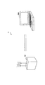
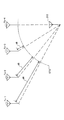
図18は、一例として4本の送信アンテナから送信された無線信号が受信アンテナ310に届く様子を概念的に示した説明図である。図18を参照すると、送信アンテナTx−1、Tx−2、Tx−3及びTx−4から受信アンテナ310までの無線信号の行路が示されている。これら送信アンテナTx−1、Tx−2、Tx−3及びTx−4は、例えば図16に示したような送信装置52に設けられる。
FIG. 18 is an explanatory diagram conceptually showing how radio signals transmitted from four transmission antennas reach the
図18において、弧STDは、受信アンテナ310との間に、送信アンテナTx−4から受信アンテナ310までの行路長と等しい距離を有する位置の軌跡を示している。
In FIG. 18, an arc STD indicates a locus of a position having a distance equal to the path length from the transmission antenna Tx-4 to the
例えば、この送信アンテナTx−4から受信アンテナ310までの行路長を基準とする。そうすると、送信アンテナTx−1についての行路差はd4、送信アンテナTx−2についての行路差はd5、送信アンテナTx−3についての行路差はd6となる。そして、これら行路差は、各送信アンテナTx−nから送信され受信アンテナ310において受信された無線信号に含まれる副搬送波ごとの位相差から求めることができる。
For example, the path length from the transmission antenna Tx-4 to the
図17に戻り、無線受信部320は、受信アンテナ310から出力された無線信号に対し、増幅、周波数変換、アナログ−デジタル変換、フィルタリング、及びインバランス補正等を行う。
Returning to FIG. 17, the
復調部330は、無線受信部320から出力された受信信号に対し、パケットの検出、同期タイミングと周波数オフセットの測定、OFDMシンボルの切り出し、高速フーリエ変換、チャネル推定等を行う。復調部330によって復調されたストリーム信号は、復号部340及び位相計算部350へ出力される。
The
復号部340は、復調部330から入力された復調済みのストリーム信号のデジタル復調及び復号を行う。復号されたデータ信号は、復号部340から例えばホストCPUへ出力される。
The
また、位相計算部350は、送信アンテナTx−nからそれぞれ送信された各無線信号について、復調部330によって復調されたストリーム信号に含まれる副搬送波ごとに、任意の基準信号との間の位相差を計算する。位相差の計算は、基準信号の複素共役値と副搬送波ごとの信号値とを乗算することにより行ってもよい。さらに、位相計算部350は、計算した位相差を用いて、各送信アンテナTx−nについての位相差平均と位相勾配とを計算する。
Further, the
そして、行路差計算部360は、位相計算部350により計算された各送信アンテナについての位相差平均と位相勾配に基づいて、送信アンテナTx−nのうち任意の2つの送信アンテナTx−nから受信アンテナ310までの行路差を計算する。行路差の計算は、例えば前述した式(1)〜式(11)に従って行われる。
Then, the path
ここで、受信装置300は、受信アンテナ310から送信アンテナTx−nまでの行路差を得られたとしても、送信アンテナTx−nの相互の位置関係が分からなければ、送受信装置の位置を特定することができない。
Here, even if the path difference from the
そこで、本実施形態では、送信装置52において例えば図6に示したパケットのデータ部(DATA)等に各送信アンテナTx−nの位置情報を挿入する。そして、受信装置300では、復号部340が復号したデータ信号を位置推定部370へ出力し、位置推定部370が各送信アンテナTx−nの当該位置情報を取得する。
Therefore, in the present embodiment, in the
例えば、送信装置52においてパケットのデータ部に各送信アンテナTx−nの絶対位置情報を挿入したとする。その場合、受信装置300の位置推定部370は、復号部340が復号したデータ信号の中から当該絶対位置情報を取得する。そして、位置推定部370は、取得した絶対位置情報と送信アンテナTx−nのうち2組以上の送信アンテナTx−nの行路差に基づいて、図10〜図12を用いて説明した手法により、受信アンテナ310の絶対位置を推定することができる。
For example, it is assumed that the
このような位置推定方法は、一例として図16に示したように、送信装置52が固定された無線アクセスポイント(又は無線基地局など)、受信装置300が移動可能な端末装置であった場合には特に有効である。その場合、送信装置52は、例えば自らの記憶装置に自装置の絶対位置情報を記録しておき、受信装置300へ送信するパケットにその絶対位置情報を含めて送信してもよい。
For example, as shown in FIG. 16, such a position estimation method is used when the transmitting
ここまで、図16〜図18を用いて、本発明の第3の実施形態に係る送信装置52及び受信装置300について説明を行った。本実施形態によれば、送信装置52に設けた複数の送信アンテナTx−nから受信装置300へ、周波数の異なる副搬送波が多重化された無線信号が送信される。受信装置300の位相計算部350は、複数の送信アンテナから受信された前述の各無線信号について、基準信号との間の副搬送波ごとの位相差を計算する。そして、行路差計算部360は、位相計算部350により計算された位相差に基づいて、任意の2つの送信アンテナTx−nから受信アンテナ310までの行路差を計算する。
So far, the
このとき、送信アンテナTx−nの絶対位置情報が例えば無線信号のデータ部を用いて受信装置300へ送信され、受信装置300の位置推定部370によって取得される。それにより、位置推定部370は、取得した絶対位置情報と前述の行路差とに基づいて、受信装置300の受信アンテナ310の絶対位置を推定することができる。
At this time, the absolute position information of the transmitting antenna Tx-n is transmitted to the receiving
ここで、本明細書において説明した第1〜第3の実施形態に係る一連の処理をハードウェアで実現するかソフトウェアで実現するかは問わない。一連の処理又はその一部をソフトウェアで実行させる場合には、ソフトウェアを構成するプログラムが、専用のハードウェアに組み込まれたコンピュータ、又は例えば図19に示した汎用コンピュータなどを用いて実行される。 Here, it does not matter whether the series of processing according to the first to third embodiments described in this specification is realized by hardware or software. When a series of processes or a part thereof is executed by software, a program constituting the software is executed by using a computer incorporated in dedicated hardware or a general-purpose computer shown in FIG.
図19において、CPU(Central Processing Unit)902は、汎用コンピュータの動作全般を制御する。ROM(Read Only Memory)904には、一連の処理の一部又は全部を記述したプログラム又はデータが格納される。RAM(Random Access Memory)906には、CPU902が演算処理に用いるプログラムやデータなどが一時的に記憶される。
In FIG. 19, a CPU (Central Processing Unit) 902 controls the overall operation of the general-purpose computer. A ROM (Read Only Memory) 904 stores a program or data describing a part or all of a series of processes. A RAM (Random Access Memory) 906 temporarily stores programs and data used by the
CPU902、ROM904、及びRAM906は、バス908を介して相互に接続される。バス908にはさらに、入出力インタフェース910が接続される。
The
入出力インタフェース910は、CPU902、ROM904、及びRAM906と、入力部912、出力部914、記憶部916、通信部918、及びドライブ920とを接続するためのインタフェースである。
The input /
入力部912は、例えばボタン、スイッチ、レバー、マウスやキーボードなどの入力装置を介して、利用者からの指示や情報入力を受け付ける。出力部914は、例えばCRT(Cathode Ray Tube)、液晶ディスプレイ、OLED(Organic Light Emitting Diode)などの表示装置、又はスピーカなどの音声出力装置を介して利用者に対して情報を出力する。
The
記憶部916は、例えばハードディスクドライブ又はフラッシュメモリなどにより構成され、プログラム、プログラムデータ、画像データなどを記憶する。通信部918は、LAN(Local Area Network)又はインターネットなどのネットワークを介する通信処理を行う。ドライブ920は、必要に応じて汎用コンピュータに設けられ、例えばドライブ920にはリムーバブルメディア922が装着される。
The
第1〜第3の実施形態に係る一連の処理をソフトウェアで実行する場合には、例えば図19に示したROM904、記憶部916、又はリムーバブルメディア922に格納されたプログラムが、実行時にRAM906に読み込まれ、CPU902によって実行される。
When the series of processing according to the first to third embodiments is executed by software, for example, a program stored in the
以上、添付図面を参照しながら本発明の好適な実施形態について説明したが、本発明は係る例に限定されないことは言うまでもない。当業者であれば、特許請求の範囲に記載された範疇内において、各種の変更例又は修正例に想到し得ることは明らかであり、それらについても当然に本発明の技術的範囲に属するものと了解される。 As mentioned above, although preferred embodiment of this invention was described referring an accompanying drawing, it cannot be overemphasized that this invention is not limited to the example which concerns. It will be apparent to those skilled in the art that various changes and modifications can be made within the scope of the claims, and these are naturally within the technical scope of the present invention. Understood.
例えば、図13を用いて説明した第1の実施形態に係る位置推定処理を、必ずしもフローチャートに記載された順序に沿って実行しなくてもよい。各処理ステップは、並列的あるいは個別に独立して実行される処理を含んでもよい。 For example, the position estimation process according to the first embodiment described with reference to FIG. 13 is not necessarily performed in the order described in the flowchart. Each processing step may include processing executed in parallel or individually independently.
1、3 無線通信システム
50、52 送信装置
100、200、300 受信装置
110−n、310 受信アンテナ
150、350 位相計算部
160、260、360 行路差計算部
170、370 位置推定部
280 制御部(周波数制御部)
1, 3
Claims (15)
前記複数の受信アンテナにより受信された各無線信号について当該無線信号に含まれる前記副搬送波ごとに基準信号との間の位相差を計算し、計算した前記副搬送波ごとの前記位相差を用いて前記受信アンテナごとに位相差平均と位相勾配とをさらに計算する位相計算部と;
前記位相計算部により計算された前記位相差平均と前記位相勾配とに基づいて、前記無線信号が送信された送信アンテナから前記複数の受信アンテナのうち任意の2つの受信アンテナまでの距離の差である行路差を計算する行路差計算部と;
を備える受信装置。 A plurality of receiving antennas each receiving a radio signal in which subcarriers having different frequencies are multiplexed;
Wherein the phase difference between the reference signal calculated with the plurality of the radio signals received by the receiving antenna for each of the subcarriers contained in this radio signal, using the phase difference for each calculated the subcarriers A phase calculator for further calculating a phase difference average and a phase gradient for each of the receiving antennas ;
Based on the phase difference average calculated by the phase calculation unit and the phase gradient, the difference in distance from the transmitting antenna from which the radio signal is transmitted to any two receiving antennas among the plurality of receiving antennas. A path difference calculation unit for calculating a certain path difference;
A receiving device.
前記受信装置は:
前記行路差計算部によって2組以上の受信アンテナについて計算された前記行路差を用いて前記送信アンテナの位置を推定する位置推定部;
をさらに備える、
請求項1に記載の受信装置。 The path difference calculating unit calculates the path difference for two or more sets of receiving antennas among the plurality of receiving antennas;
The receiver is:
A position estimation unit that estimates the position of the transmission antenna using the path difference calculated for two or more sets of reception antennas by the path difference calculation unit;
Further comprising
The receiving device according to claim 1.
前記位相計算部により複数回計算された複数の前記位相差を用いて、前記行路差計算部により計算される前記行路差に含まれる誤差が低減される、
請求項1に記載の受信装置。 The phase calculation unit calculates, for each radio signal received by the plurality of receiving antennas, the phase difference between the reference signal for each subcarrier included in the radio signal a plurality of times ,
Before SL by using a plurality of the phase differences calculated a plurality of times by the phase calculating section, an error included in the path difference which is calculated by the path difference calculation section is reduced,
The receiving device according to claim 1.
前記複数の受信アンテナにより受信される無線信号の周波数帯を制御する制御部;
をさらに備え;
前記複数の受信アンテナは、前記制御部による制御に応じて、周波数の異なる副搬送波がそれぞれ多重化された第1の周波数帯の無線信号と第2の周波数帯の無線信号とを受信し;
前記行路差計算部は、前記第1の周波数帯の無線信号について計算された前記受信アンテナごとの第1の位相勾配と、前記第2の周波数帯の無線信号について計算された前記受信アンテナごとの第2の位相勾配とを用いて、前記行路差の計算に用いる位相勾配の誤差を低減させる;
請求項1に記載の受信装置。 The receiver is:
A control unit for controlling a frequency band of radio signals received by the plurality of receiving antennas;
Further comprising:
The plurality of receiving antennas receive a radio signal in a first frequency band and a radio signal in a second frequency band each of which is multiplexed with subcarriers having different frequencies according to control by the control unit;
The path difference calculation unit calculates a first phase gradient for each of the reception antennas calculated for the radio signal in the first frequency band and a frequency for each of the reception antennas calculated for a radio signal in the second frequency band. Using a second phase gradient to reduce the phase gradient error used to calculate the path difference;
The receiving device according to claim 1 .
前記受信アンテナにより受信された各無線信号について当該無線信号に含まれる前記副搬送波ごとに基準信号との間の位相差を計算し、計算した前記基準信号との間の前記副搬送波ごとの前記位相差を用いて、前記送信アンテナごとに位相差平均と位相勾配とをさらに計算する位相計算部と;
前記位相計算部により計算された前記位相差平均と前記位相勾配とに基づいて、前記無線信号が送信された前記複数の送信アンテナのうち任意の2つの送信アンテナから前記受信アンテナまでの距離の差である行路差を計算する行路差計算部と;
を備える受信装置。 A receiving antenna for receiving a plurality of radio signals transmitted from a plurality of transmitting antennas, each of which is a radio signal in which subcarriers having different frequencies are multiplexed;
Wherein the phase difference between the reference signal and calculates information on the radio signal received by the receiving antenna for each of the subcarriers contained in this radio signal, for each of the subcarriers between the calculated and the reference signal A phase calculation unit that further calculates a phase difference average and a phase gradient for each of the transmission antennas using the phase difference ;
Based on the phase difference average calculated by the phase calculator and the phase gradient, a difference in distance from any two transmitting antennas to the receiving antenna among the plurality of transmitting antennas to which the radio signal is transmitted. A path difference calculation unit for calculating a path difference that is;
A receiving device.
前記受信装置は:
前記行路差計算部によって2組以上の送信アンテナについて計算された前記行路差を用いて自装置の位置を推定する位置推定部;
をさらに備える、
請求項8に記載の受信装置。 The path difference calculation unit calculates the path difference for two or more sets of the transmission antennas;
The receiver is:
A position estimator for estimating the position of the own apparatus using the path differences calculated for two or more sets of transmission antennas by the path difference calculator;
Further comprising
The receiving device according to claim 8 .
を備える送信装置と:
前記複数の送信アンテナから送信された複数の無線信号を受信する受信アンテナ;
前記受信アンテナにより受信された各無線信号について当該無線信号に含まれる前記副搬送波ごとに基準信号との間の位相差を計算し、計算した前記基準信号との間の前記副搬送波ごとの前記位相差を用いて前記送信アンテナごとに位相差平均と位相勾配とをさらに計算する位相計算部;
及び、前記位相計算部により計算された前記位相差平均と前記位相勾配とに基づいて、前記無線信号が送信された前記複数の送信アンテナのうち任意の2つの送信アンテナから前記受信アンテナまでの距離の差である行路差を計算する行路差計算部;
を備える受信装置と:
を含む無線通信システム。 A plurality of transmission antennas each transmitting a radio signal in which subcarriers having different frequencies are multiplexed;
A transmission device comprising:
A receiving antenna for receiving a plurality of radio signals transmitted from the plurality of transmitting antennas;
Wherein the phase difference between the reference signal and calculates information on the radio signal received by the receiving antenna for each of the subcarriers contained in this radio signal, for each of the subcarriers between the calculated and the reference signal A phase calculation unit that further calculates a phase difference average and a phase gradient for each of the transmission antennas using the phase difference ;
And based on the phase difference average calculated by the phase calculation unit and the phase gradient, a distance from any two transmission antennas to the reception antenna among the plurality of transmission antennas to which the radio signal is transmitted A path difference calculation unit for calculating a path difference which is a difference between
A receiving device comprising:
A wireless communication system including:
前記受信装置は:
前記行路差計算部によって2組以上の送信アンテナについて計算された前記行路差を用いて自装置の相対位置を推定する位置推定部;
をさらに備える、
請求項11に記載の無線通信システム。 The path difference calculation unit of the receiving device calculates the path difference for two or more sets of the transmission antennas;
The receiver is:
A position estimator that estimates a relative position of the own apparatus using the path differences calculated for two or more sets of transmission antennas by the path difference calculator;
Further comprising
The wireless communication system according to claim 11 .
前記受信装置の前記位置推定部は、前記無線信号から取得した前記複数の送信アンテナの前記絶対位置に関する情報を用いて自装置の絶対位置を推定する、
請求項12に記載の無線通信システム。 The transmitting device transmits information on absolute positions of the plurality of transmitting antennas to the receiving device using the radio signal;
The position estimating unit of the receiving apparatus estimates the absolute position of the own apparatus using information on the absolute positions of the plurality of transmitting antennas acquired from the radio signal;
The wireless communication system according to claim 12 .
前記複数の受信アンテナにより受信された各無線信号について、当該無線信号に含まれる前記副搬送波ごとに基準信号との間の位相差を計算するステップと;
計算された前記副搬送波ごとの前記位相差を用いて、前記受信アンテナごとに位相差平均と位相勾配とを計算するステップと、
計算された前記位相差平均と前記位相勾配とに基づいて、前記無線信号が送信された送信アンテナから前記複数の受信アンテナのうち任意の2つの受信アンテナまでの距離の差である行路差を計算するステップと;
を含む位置推定方法。 Receiving radio signals multiplexed with subcarriers having different frequencies by a plurality of receiving antennas;
Calculating a phase difference between each radio signal received by the plurality of receiving antennas and a reference signal for each of the subcarriers included in the radio signal;
Calculating a phase difference average and a phase gradient for each of the receiving antennas using the calculated phase difference for each of the subcarriers;
Based on the calculated phase difference average and the phase gradient , a path difference that is a difference in distance from the transmitting antenna from which the radio signal is transmitted to any two receiving antennas among the plurality of receiving antennas is calculated. Step to do;
A position estimation method including:
前記複数の受信アンテナにより受信された各無線信号について当該無線信号に含まれる前記副搬送波ごとに基準信号との間の位相差を計算し、計算した前記副搬送波ごとの前記位相差を用いて前記受信アンテナごとに位相差平均と位相勾配とをさらに計算する位相計算部と;
前記位相計算部により計算された前記位相差平均と前記位相勾配とに基づいて、前記無線信号が送信された送信アンテナから前記複数の受信アンテナのうち任意の2つの受信アンテナまでの距離の差である行路差を計算する行路差計算部と;
として機能させるためのプログラム。
A computer for controlling a receiving apparatus having a plurality of receiving antennas that respectively receive radio signals multiplexed with subcarriers having different frequencies:
Wherein the phase difference between the reference signal calculated with the plurality of the radio signals received by the receiving antenna for each of the subcarriers contained in this radio signal, using the phase difference for each calculated the subcarriers A phase calculator for further calculating a phase difference average and a phase gradient for each of the receiving antennas ;
Based on the phase difference average calculated by the phase calculation unit and the phase gradient, the difference in distance from the transmitting antenna from which the radio signal is transmitted to any two receiving antennas among the plurality of receiving antennas. A path difference calculation unit for calculating a certain path difference;
Program to function as.
Priority Applications (2)
| Application Number | Priority Date | Filing Date | Title |
|---|---|---|---|
| JP2008182961A JP4591565B2 (en) | 2008-07-14 | 2008-07-14 | Reception device, wireless communication system, position estimation method, and program |
| US12/498,807 US8456362B2 (en) | 2008-07-14 | 2009-07-07 | Receiving apparatus, radio communication system, position estimation method and program |
Applications Claiming Priority (1)
| Application Number | Priority Date | Filing Date | Title |
|---|---|---|---|
| JP2008182961A JP4591565B2 (en) | 2008-07-14 | 2008-07-14 | Reception device, wireless communication system, position estimation method, and program |
Publications (2)
| Publication Number | Publication Date |
|---|---|
| JP2010019803A JP2010019803A (en) | 2010-01-28 |
| JP4591565B2 true JP4591565B2 (en) | 2010-12-01 |
Family
ID=41505583
Family Applications (1)
| Application Number | Title | Priority Date | Filing Date |
|---|---|---|---|
| JP2008182961A Expired - Fee Related JP4591565B2 (en) | 2008-07-14 | 2008-07-14 | Reception device, wireless communication system, position estimation method, and program |
Country Status (2)
| Country | Link |
|---|---|
| US (1) | US8456362B2 (en) |
| JP (1) | JP4591565B2 (en) |
Families Citing this family (18)
| Publication number | Priority date | Publication date | Assignee | Title |
|---|---|---|---|---|
| US8577387B2 (en) * | 2009-03-17 | 2013-11-05 | Qualcomm Incorporated | Position location using multiple carriers |
| US8619908B2 (en) * | 2009-12-02 | 2013-12-31 | Harris Corporation | Wireless ranging system and related methods |
| JP5208994B2 (en) * | 2010-05-14 | 2013-06-12 | 中国電力株式会社 | Evacuation guidance method and information processing system used for this method |
| EP2535738B1 (en) * | 2011-06-15 | 2019-08-07 | Airbus Defence and Space GmbH | Improved antenna beam forming for tracking a transmitter signal |
| KR20150104346A (en) * | 2014-03-05 | 2015-09-15 | 서울시립대학교 산학협력단 | System and method for calculating arrangement data between devices |
| JP6381134B2 (en) * | 2015-03-31 | 2018-08-29 | 三菱重工機械システム株式会社 | Radio wave arrival angle detection device, vehicle detection system, radio wave arrival angle detection method, and vehicle false detection prevention method |
| JP6401671B2 (en) * | 2015-07-15 | 2018-10-10 | 日本電信電話株式会社 | Position detection apparatus and position detection method |
| WO2017028874A1 (en) * | 2015-08-14 | 2017-02-23 | Sony Mobile Communications Inc. | Determining a relative position between devices |
| CN105652240A (en) * | 2015-12-29 | 2016-06-08 | 南京工程学院 | Rail transit vehicle door motion track measurement system and rail transit vehicle door motion track measurement method |
| WO2017202459A1 (en) * | 2016-05-25 | 2017-11-30 | Fraunhofer-Gesellschaft zur Förderung der angewandten Forschung e.V. | Waveform design for locating system |
| EP3316508A1 (en) * | 2016-10-27 | 2018-05-02 | Fraunhofer Gesellschaft zur Förderung der Angewand | Receiver and method for providing a phase coherency for frequency hopping multitone signals |
| EP3316534A1 (en) | 2016-10-27 | 2018-05-02 | Fraunhofer Gesellschaft zur Förderung der Angewand | Channel estimation of frequency sub bands |
| US11269046B2 (en) * | 2017-10-12 | 2022-03-08 | U-Blox Ag | Phase-comparison of multi-frequency transmissions for assisting the determination of position or time |
| JP6781505B2 (en) * | 2018-04-23 | 2020-11-04 | 三菱電機株式会社 | Displacement measuring device |
| CN109085563B (en) * | 2018-06-26 | 2022-06-21 | 重庆邮电大学 | WLAN ranging method based on software radio platform |
| US10935668B2 (en) * | 2018-08-28 | 2021-03-02 | Bae Systems Information And Electronic Systems Integration Inc. | System and method for determining geolocation of a signal source |
| US10499363B1 (en) * | 2018-09-18 | 2019-12-03 | Qualcomm Incorporated | Methods and apparatus for improved accuracy and positioning estimates |
| FR3110318B1 (en) * | 2020-05-13 | 2022-04-29 | Commissariat Energie Atomique | METHOD FOR LOCATING A CONNECTED OBJECT BY ARRIVAL PHASE DIFFERENCES IN AN LPWA NETWORK |
Citations (7)
| Publication number | Priority date | Publication date | Assignee | Title |
|---|---|---|---|---|
| JPH09257902A (en) * | 1996-03-22 | 1997-10-03 | Mitsubishi Electric Corp | Bearing detecting device |
| JP2001201550A (en) * | 2000-01-18 | 2001-07-27 | Yrp Mobile Telecommunications Key Tech Res Lab Co Ltd | Incoming wave estimation device |
| JP2004333252A (en) * | 2003-05-06 | 2004-11-25 | Nippon Telegr & Teleph Corp <Ntt> | Apparatus and method for inferring position |
| JP2006023261A (en) * | 2003-07-28 | 2006-01-26 | Rcs:Kk | Active tag device |
| JP2006042201A (en) * | 2004-07-29 | 2006-02-09 | Advanced Telecommunication Research Institute International | Distance measurement system, distance measuring method and communication equipment |
| JP2007212424A (en) * | 2006-01-10 | 2007-08-23 | Rcs:Kk | Position detecting device and position detection program |
| JP2009287942A (en) * | 2008-05-27 | 2009-12-10 | Mitsubishi Electric Corp | Direction finder |
Family Cites Families (5)
| Publication number | Priority date | Publication date | Assignee | Title |
|---|---|---|---|---|
| JPS6466582A (en) * | 1987-09-08 | 1989-03-13 | Nec Corp | System for detecting propagation time of transmission line |
| JP4561329B2 (en) * | 2004-11-18 | 2010-10-13 | ソニー株式会社 | Ranging system, transmitting terminal, receiving terminal, ranging method, and computer program |
| KR100778309B1 (en) * | 2005-12-08 | 2007-11-22 | 한국전자통신연구원 | Apparatus and Method for computing location of a moving beacon using received signal strength and multi-frequencies |
| KR100904681B1 (en) * | 2005-12-15 | 2009-06-25 | 한국전자통신연구원 | Method and apparatus for transmitter locating using a single receiver |
| WO2008029812A1 (en) * | 2006-09-05 | 2008-03-13 | Radio Communication Systems Ltd. | Distance measuring device |
-
2008
- 2008-07-14 JP JP2008182961A patent/JP4591565B2/en not_active Expired - Fee Related
-
2009
- 2009-07-07 US US12/498,807 patent/US8456362B2/en active Active
Patent Citations (7)
| Publication number | Priority date | Publication date | Assignee | Title |
|---|---|---|---|---|
| JPH09257902A (en) * | 1996-03-22 | 1997-10-03 | Mitsubishi Electric Corp | Bearing detecting device |
| JP2001201550A (en) * | 2000-01-18 | 2001-07-27 | Yrp Mobile Telecommunications Key Tech Res Lab Co Ltd | Incoming wave estimation device |
| JP2004333252A (en) * | 2003-05-06 | 2004-11-25 | Nippon Telegr & Teleph Corp <Ntt> | Apparatus and method for inferring position |
| JP2006023261A (en) * | 2003-07-28 | 2006-01-26 | Rcs:Kk | Active tag device |
| JP2006042201A (en) * | 2004-07-29 | 2006-02-09 | Advanced Telecommunication Research Institute International | Distance measurement system, distance measuring method and communication equipment |
| JP2007212424A (en) * | 2006-01-10 | 2007-08-23 | Rcs:Kk | Position detecting device and position detection program |
| JP2009287942A (en) * | 2008-05-27 | 2009-12-10 | Mitsubishi Electric Corp | Direction finder |
Also Published As
| Publication number | Publication date |
|---|---|
| US8456362B2 (en) | 2013-06-04 |
| US20100009644A1 (en) | 2010-01-14 |
| JP2010019803A (en) | 2010-01-28 |
Similar Documents
| Publication | Publication Date | Title |
|---|---|---|
| JP4591565B2 (en) | Reception device, wireless communication system, position estimation method, and program | |
| US11513181B2 (en) | Angle of arrival location sensing with antenna array | |
| JP4666031B2 (en) | Synchronous circuit and wireless communication device | |
| JP4900360B2 (en) | Reception device, moving angle estimation method, program, and wireless communication system | |
| EP2795356B1 (en) | An apparatus and associated methods for switching between antennas in a multi-antenna receiver | |
| EP3531645B1 (en) | Reference signal configuration method, training field configuration method, and apparatus | |
| CN101924730B (en) | Method for correcting phase demodulating error of orthogonal frequency multichannel signal | |
| JP5141344B2 (en) | Receiving apparatus, program, and receiving method | |
| US8045948B2 (en) | Receiving apparatus, program and receiving method | |
| JP2009296552A (en) | Receiving device, receiving method and wireless communication system | |
| WO2012155459A1 (en) | Method and device for correcting frequency offset | |
| JP2006014027A5 (en) | ||
| US9059887B2 (en) | Receiving device and receiving method for determining doppler frequency from pilot signals using OFDM | |
| US20220381868A1 (en) | Angle of arrival estimation using a single receive chain | |
| US8964789B1 (en) | Method and system for data synchronization in communication systems using repetitive preamble patterns | |
| CN114650595A (en) | Indoor positioning method, device, equipment and medium | |
| JP5234318B2 (en) | Automatic frequency control method and apparatus | |
| RU2577316C2 (en) | Signal processing device, signal processing method and programme | |
| JP5657733B2 (en) | Acquisition of timing information in wireless communication systems | |
| JP2010074564A (en) | Packet detecting apparatus and packet detecting method, distance measuring device and distance measuring method, communication device, and computer program | |
| KR100929705B1 (en) | Timing synchronization apparatus for wireless communication system | |
| JP2011015078A (en) | Receiver | |
| JP2012090142A (en) | Radio wave environment measurement device |
Legal Events
| Date | Code | Title | Description |
|---|---|---|---|
| A977 | Report on retrieval |
Free format text: JAPANESE INTERMEDIATE CODE: A971007 Effective date: 20100416 |
|
| A131 | Notification of reasons for refusal |
Free format text: JAPANESE INTERMEDIATE CODE: A131 Effective date: 20100427 |
|
| A521 | Request for written amendment filed |
Free format text: JAPANESE INTERMEDIATE CODE: A523 Effective date: 20100615 |
|
| TRDD | Decision of grant or rejection written | ||
| A01 | Written decision to grant a patent or to grant a registration (utility model) |
Free format text: JAPANESE INTERMEDIATE CODE: A01 Effective date: 20100817 |
|
| A01 | Written decision to grant a patent or to grant a registration (utility model) |
Free format text: JAPANESE INTERMEDIATE CODE: A01 |
|
| A61 | First payment of annual fees (during grant procedure) |
Free format text: JAPANESE INTERMEDIATE CODE: A61 Effective date: 20100830 |
|
| FPAY | Renewal fee payment (event date is renewal date of database) |
Free format text: PAYMENT UNTIL: 20130924 Year of fee payment: 3 |
|
| R151 | Written notification of patent or utility model registration |
Ref document number: 4591565 Country of ref document: JP Free format text: JAPANESE INTERMEDIATE CODE: R151 |
|
| FPAY | Renewal fee payment (event date is renewal date of database) |
Free format text: PAYMENT UNTIL: 20130924 Year of fee payment: 3 |
|
| R250 | Receipt of annual fees |
Free format text: JAPANESE INTERMEDIATE CODE: R250 |
|
| R250 | Receipt of annual fees |
Free format text: JAPANESE INTERMEDIATE CODE: R250 |
|
| R250 | Receipt of annual fees |
Free format text: JAPANESE INTERMEDIATE CODE: R250 |
|
| R250 | Receipt of annual fees |
Free format text: JAPANESE INTERMEDIATE CODE: R250 |
|
| R250 | Receipt of annual fees |
Free format text: JAPANESE INTERMEDIATE CODE: R250 |
|
| R250 | Receipt of annual fees |
Free format text: JAPANESE INTERMEDIATE CODE: R250 |
|
| R250 | Receipt of annual fees |
Free format text: JAPANESE INTERMEDIATE CODE: R250 |
|
| LAPS | Cancellation because of no payment of annual fees |