JP4590310B2 - Optical equipment - Google Patents
Optical equipment Download PDFInfo
- Publication number
- JP4590310B2 JP4590310B2 JP2005165354A JP2005165354A JP4590310B2 JP 4590310 B2 JP4590310 B2 JP 4590310B2 JP 2005165354 A JP2005165354 A JP 2005165354A JP 2005165354 A JP2005165354 A JP 2005165354A JP 4590310 B2 JP4590310 B2 JP 4590310B2
- Authority
- JP
- Japan
- Prior art keywords
- screw
- thread
- rack
- feed
- feed screw
- Prior art date
- Legal status (The legal status is an assumption and is not a legal conclusion. Google has not performed a legal analysis and makes no representation as to the accuracy of the status listed.)
- Expired - Fee Related
Links
Images


Landscapes
- Lens Barrels (AREA)
- Transmission Devices (AREA)
Description
本発明は、回転する送りねじと、それに噛み合うねじラックなどを用いて構成された移動装置を備え、レンズ等の光学系を直進移動させる光学機器に関するものである。 The present invention relates to an optical apparatus that includes a moving device configured by using a rotating feed screw and a screw rack that meshes with the screw, and moves an optical system such as a lens in a straight line .
送りねじとねじラックなどを利用した移動装置を具備した光学機器は特許文献1に開示されている。この種の光学機器は、レンズ鏡筒枠に取り付けられた雌ねじあるいはねじラックとモータなどの駆動源により駆動される送りねじとの噛み合いによりレンズ群を光軸方向に移動するよう構成されている。 An optical apparatus including a moving device using a feed screw and a screw rack is disclosed in Patent Document 1. This type of optical apparatus is configured to move the lens group in the optical axis direction by meshing between a female screw or a screw rack attached to the lens barrel frame and a feed screw driven by a driving source such as a motor.
この構成において重要な機能は主に次の3点である。第1に、通常送りの際にモータの回転トルクが効率良くねじラックの推進力に変換されているか、第2に、光学機器を振った場合や落下などの衝撃を受けた際などにねじラックが送りねじから外れる「歯飛び」が発生しないか、第3に、ねじラックが移動の終端に当接した際、送りねじを逆転しても復帰できないという、いわゆる「喰いつき」が発生しないか、である。 The important functions in this configuration are mainly the following three points. First, the rotational torque of the motor is efficiently converted into the propulsive force of the screw rack during normal feeding, or second, the screw rack when the optical equipment is shaken or when it receives an impact such as dropping. Doesn't “tooth jump” occur when the screw rack comes off from the feed screw, or thirdly, when the screw rack comes into contact with the end of movement, does not cause so-called “biting” that cannot be restored even if the feed screw is reversed? .
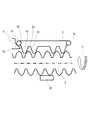
ここで、上記特許文献1に開示された移動装置を図4に示す。図4において、11はステッピングモータ等のアクチュエータ、12はアクチュエータ11によって回転駆動される送りねじ、13は送りねじ12と噛み合い該送りねじ12の回転によって矢印AまたはB方向に直進運動するねじラックである。15は支持台であり、両端部の垂直支持壁15a,15b間に送りねじ12が軸受け部材16を介して、回転自在に支持されている。また、一方の垂直支持壁15bにアクチュエータ11がねじ17で取り付けられている。
Here, FIG. 4 shows the moving device disclosed in Patent Document 1. In FIG. 4, 11 is an actuator such as a stepping motor, 12 is a feed screw that is rotationally driven by the
上記ねじラック13は図4のZ方向から見た図5乃至図7に示すように、送りねじ12に接する送り歯13a、不図示のバネ部材によるバネ圧によって送り歯13aを送りねじ12に押し付ける押し付け部13b、ねじラック移動方向の衝撃が加わったときの落下衝撃対策として、送り歯13aがねじ山を乗り越えないように設けられた対向歯13cを備えている。14はねじラック13の可動範囲を制限するストッパ(機械端)であり、図5〜図7では左端のストッパのみを図示したが、不図示の右端のストッパも存在する。
As shown in FIGS. 5 to 7 when viewed from the Z direction in FIG. 4, the
次に、動作について説明する。通常送りの際は、図5に示すように、送りねじ12のねじ山が安定してねじラック13の送り歯と噛み合う為に最小限の力で押し付け部13bが送りねじ12を挟み込んでおり、光学機器が軸方向の加速度を受けた際には、その挟み込み力を容易に越えて歯が外れようとするが、その際に対向歯13cが上記加速度を受ける働きをし、歯飛びを防止する。従って、対向歯13cは送り歯13aに対し、所定の剛性を持っている。
Next, the operation will be described. At the time of normal feeding, as shown in FIG. 5, since the thread of the
図6は、送りねじ12が矢印a方向に回転し、ねじラック13が図中左方向に移動して、ストッパ14に当接した瞬間を示している。この状態からさらに、送りねじ12が矢印a方向に回転すると、図6に示すように、送りねじ12のねじ山は左に進むが、ねじラック13はストッパ14に当たって動けないため、送りねじ12のねじ山の斜面に沿って乗り上がっていく。このとき、対向歯13cも送りねじ2のねじ山に接触し、ねじ山の斜面に沿って乗り上がり、ねじラック13の送り歯13aと対向歯13cの間隔が弾性変形して広がり、ついには図7に示すように、送りねじ12のねじ山頂点と、ねじラック13の送り歯13aの頂点が接し、且つ、送りねじ12のねじ山頂点と対向歯3cの頂点とが接するところまでねじラック13の送り歯13aと対向歯13cの間隔が広がる。
上記従来例では、対向歯13cと送り歯13aの間の剛性を越えてねじラック13が弾性変形してしまうので、送りねじ12の挟み込み力としては予期しない大きさとなり、大きな摩擦力が発生する。よって、図7の状態で送りねじ12の回転が一度止まると、再起動時にアクチュエータ11の力だけでは動けなくなるという、喰いつき現象が生じていた。
In the above conventional example, since the
ここで、上記従来例の送りねじによる移動装置の問題点を送りねじのねじ山形状の観点から詳述する。 Here, the problems of the moving device using the conventional feed screw will be described in detail from the viewpoint of the thread shape of the feed screw.
始めに、通常送り時について述べる。送りねじの回転トルクが効率良く推進力となる機構が好ましい。通常動作時、ねじラックと送りねじのねじ山が噛み合ってねじ山の斜面で送りねじの進み力が分力されるが、これが頂角の小さいねじ山の場合、推進力である軸方向に分力される力が大きく、径方向に分力される力は小さい。従って、安定した噛み合いを保証する為の送りねじに対する挟み込み力は小さくて良く、不要な摩擦ロスも少なくて効率が良い。一方で頂角の大きいねじ山は反対の特性を有する。 First, normal feeding will be described. A mechanism in which the rotational torque of the feed screw efficiently provides a driving force is preferable. During normal operation, the thread of the screw rack and the feed screw mesh with each other, and the advance force of the feed screw is divided on the slope of the screw thread. If this is a screw thread with a small apex angle, it is divided in the axial direction as the propulsive force. The force applied is large, and the force applied in the radial direction is small. Therefore, the pinching force with respect to the feed screw for assuring a stable engagement may be small, and there is little unnecessary friction loss, and the efficiency is high. On the other hand, threads with a large apex angle have the opposite characteristics.
次に、落下衝撃対策(歯飛び対策)について述べる。装置に落下や衝撃が加わると、軸方向の加速度が発生し、これはねじラックのねじ山に伝達され、頂角の大きいねじ山では噛み合いが外れる、いわゆる歯飛びを発生しやすい。これを防ぐ為に、所定の加速度に耐えるように挟み込み力を増大させたり、ねじラックの送りねじの反対側に落下時のみ、ねじ山に噛み合う対向歯を設けたりした。 Next, a drop impact countermeasure (tooth skip countermeasure) will be described. When a drop or impact is applied to the apparatus, axial acceleration is generated, which is transmitted to the thread of the screw rack, and the thread having a large apex angle is easily disengaged, so-called tooth skipping is likely to occur. In order to prevent this, the pinching force is increased so as to withstand a predetermined acceleration, or opposed teeth that engage with the screw thread only when dropped on the opposite side of the screw rack feed screw are provided.
しかしながら、挟み込み力を増大させると、送りに際しての機械ロスが大きくなり、効率が低下する。また、ねじラックに対向歯を設けると、ねじラックの大型化につながっていた。 However, when the pinching force is increased, the mechanical loss during feeding increases and the efficiency decreases. In addition, providing opposing teeth on the screw rack has led to an increase in the size of the screw rack.
最後に、喰いつき対策について述べる。ねじラックの移動の終端においてストッパ衝突に際して送り歯と対向歯の間が広げられることにより、喰いつきが発生する。つまり、本来、前述した落下衝撃対策として追加された対向歯がある為に、移動の終端においては副作用として喰いつきが発生していることになる。よって、例えば送りねじの終端にねじ山のない部分を設けてこれを防止している。しかしながら、副作用として送りねじに余分な機械加工工程が追加される恐れがあり、コストアップなどが懸念される。 Lastly, we will discuss countermeasures against bite. At the end of the movement of the screw rack, the gap between the feed dog and the counter teeth is widened when the stopper collides, and biting occurs. In other words, since there is an opposing tooth originally added as a countermeasure against the drop impact described above, biting occurs as a side effect at the end of movement. Therefore, for example, a portion having no thread is provided at the end of the feed screw to prevent this. However, as a side effect, an extra machining step may be added to the feed screw, which may raise costs.
上記説明した通り、従来の送りねじによる移動装置では、送りねじのねじ山に対する改善が考慮されていないので、ある対策による副作用が発生し、さらに対策を追加するという状態であった。 As described above, the conventional moving device using the feed screw does not consider the improvement of the thread of the feed screw, so that a side effect due to a certain measure occurs and a measure is added.
(発明の目的)
本発明の目的は、小型化を図りつつ、送り時の効率アップ、落下衝撃時の歯飛び、移動終端での喰いつき防止を実現することのできる光学機器を提供しようとするものである。
(Object of invention)
An object of the present invention is to provide an optical apparatus capable of realizing an increase in efficiency during feeding, tooth skipping during a drop impact, and prevention of biting at the end of movement while achieving downsizing.
上記目的を達成するために、本発明は、回転可能に支持されるねじ状の第1の部材と、該第1の部材のねじ山に噛み合い、該第1の部材の回転により該第1の部材の軸方向に移動するねじ状の第2の部材とによって構成される移動装置を備え、前記第2の部材の移動に連動して、光学系を光軸方向に移動させる光学機器において、前記第1の部材の軸方向断面に現れる前記ねじ山の山形状が、前記ねじ山の根元側にある第1の斜面、前記ねじ山の先端側にある第2の斜面、の2つの異なる頂角を有する斜面からなり、前記第1の斜面の頂角は前記第2の斜面の頂角より小さく、前記第2の部材の軸方向移動の限界を定めるために設けられるストッパ手段に、前記第2の部材を前記第1の部材の外径方向に移動させる案内部を設けた光学機器とするものである。 In order to achieve the above-mentioned object, the present invention engages with a screw-shaped first member rotatably supported and a thread of the first member, and the first member is rotated by the rotation of the first member. An optical device that includes a moving device configured by a screw-shaped second member that moves in the axial direction of the member, and that moves the optical system in the optical axis direction in conjunction with the movement of the second member ; The thread shape of the thread appearing in the axial cross section of the first member has two different apex angles: a first slope on the root side of the thread and a second slope on the tip side of the thread. The first slope is smaller than the second slope, and the second means is provided with stopper means provided to limit the axial movement of the second member. an optical device having a guide portion for moving the member to the outer diameter direction of said first member Is shall.
本発明によれば、小型化を図りつつ、送り時の効率アップ、落下衝撃時の歯飛び、移動終端での喰いつき防止を実現することができる光学機器を提供できるものである。 According to the present invention, it is possible to provide an optical apparatus capable of realizing an increase in efficiency at the time of feeding, tooth skipping at the time of a drop impact, and prevention of biting at a moving end while achieving downsizing.
本発明を実施するための最良の形態は、以下の実施例に示す通りである。 The best mode for carrying out the present invention is as shown in the following examples.
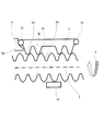
図1〜図3は本発明の一実施例に係わる移動装置を示す図であり、詳しくは、図1は通常の送り状態時における送りねじの軸方向の断面図、図2は移動の終端近傍を示す断面図、図3は移動の終端での様子を示す断面図である。 1 to 3 are views showing a moving device according to an embodiment of the present invention. Specifically, FIG. 1 is a sectional view in the axial direction of a feed screw in a normal feeding state, and FIG. FIG. 3 is a cross-sectional view showing a state at the end of movement.
これらの図において、2は、不図示の制御回路により所定のパルスが与えられてそれに対応した回転角だけ正或いは逆方向に回転する不図示のモータ(図4のアクチュエータ11に相当)により駆動されて回転するねじ状の第1の部材であるところの送りねじであり、いわゆる雄ねじであるところの各々のねじ山は異なる2種の頂角の山形からなり、そのねじ山の根元側(谷に近い側)の斜面を第1の斜面2aとし、ここではその頂角θ1を約30度のいわゆる台形山形とする。また、そのねじ山の先端側(外径側に近い側)の斜面を第2の斜面2bとし、ここではその頂角θ2を約70度の三角山形とする。2cは一つのねじ山の頂点である。
In these figures, 2 is driven by a motor (not shown) (corresponding to the
3はねじ状の第2の部材であるところのねじラックであり、注油された金属或いは摺動性の良い樹脂材料などからなり、送りねじ2の第1の斜面2aに適当な斜面で噛み合う送り歯3aが噛み合って送りねじ2の回転に伴い、ねじラック3を軸方向に移動させる。送りねじ2の回転方向が矢印aの方向の際にねじラック3が図1中、左方向に送られる。このねじラック3の直進運動に不図示のレンズ枠が連動して移動するように構成したものが、不図示の光学機器となる。3bは送りねじ2を挟み込んでバネなどで押し付けられている押し付け部であり、送り歯3aを安定して送りねじ2のねじ山に当接させている。
4はねじラック3の軸方向移動の限界を定めるストッパ手段であるところのストッパ、4aは案内部であるところのカム部である。3cはフォロワー部であり、ねじラック3の移動の終端でカム部4aに当接する位置にあって、カム部4aの斜面にスムーズに乗り上げることができる形状となっている。図1では、ねじラック3は4つの送り歯を持つが、その数は限定されるものではなく、例えば1つの歯であってもよい。また、ここでは送り歯3aはねじの噛み合いピッチが円でなく、直線であるラックを例としているが、通常の噛みあいピッチ円を有するいわゆる雌ねじの一部、であってもよい。また、例ではねじラックの軸方向の移動の限界を定めるストッパ手段は図において左側の端部のみ表示しているが、右側の端部にも同様の形状のストッパがあってもよい。
4 is a stopper which is a stopper means for determining the limit of the axial movement of the
次に、上記構成の移動装置の動作について説明を行う。通常の移動の場合、不図示のモータの正逆回転により、ねじラック3は送り歯3aが台形山形の第1の斜面2aに噛み合いながら図中右から左或いは左から右に移動している。このとき、送りねじ2のねじ山が進もうとする力Fを有しているとすると、ねじ山の第1の斜面2aにより分力されて、Fcosθ1となるF’がねじラック3に伝達される。このF’を軸方向の力と径方向の力に分力すると、ねじラック3を外径方向へ押し出す力が発生する。押し付け部3bの送りねじ2への挟み込み力は送りねじ2のねじ山の第1の斜面2aの傾き角により発生する送りねじ2の外径方向への力に抗するように設定されている。従って、第1の斜面2aのように頂角が小さい山形の斜面で発生する力は小さいので、この挟み込み力も小さくて済んでいる。
Next, the operation of the mobile device having the above configuration will be described. In the case of normal movement, the
一方、この状態において装置の落下や、急激に振り回したりした場合、不図示のレンズ枠などに送りねじ2と同軸方向の加速度がかかると、第1の斜面2aは台形山形で頂角は約30度なので過大な力がかかっても、ねじラック3が送りねじ2の外径方向への分力が少ないため、送りねじ2とねじラック3の噛み合いは外れにくい。
On the other hand, when the apparatus is dropped or swung around rapidly in this state, when acceleration in the direction coaxial with the
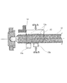
次に、図1のように移動範囲の一方の終端である左側のストッパ4のカム部4aにフォロワー部3cが接する位置に至っても、さらに続いて送りねじ2が回転している場合、ねじラック3は図1の状態からさらに図中左方向に進行しようとする。
Next, even if the
すると、図2にあるように、ねじラック3のフォロワー部3cがカム部4aに乗り上げて、ねじラック3全体を押し付け部3bの挟み込み力に抗して送りねじ2の外径側に移動させる。よって、送り歯3aと第1の斜面2aの噛み合いが外れて、送り歯3aのねじ山は第2の斜面2b上に移動する。ここで第2の斜面2bの頂角は約70度となので、第1の斜面2aに比べて送りねじ2の外径方向への分力が大きく、乗り上げによる回転負荷は大きくはない。
Then, as shown in FIG. 2, the
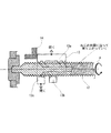
やがて、図3に示すようにフォロワー部3cがストッパ4の垂直面に当接し、ねじラック3の左右方向の移動が停止すると、これを不図示のセンサ手段による停止位置の検知信号や不図示のタイマー手段などにより検知され、この検知信号により不図示のモータの回転が停止となるように制御されることになる。
Eventually, as shown in FIG. 3, when the
しかし、上記の制御回路やセンサ手段等のトラブルなどにより万一、さらに送りねじ2の回転が続いた場合、ねじラック3の送り歯3aは送りねじ2のねじ山の第2の斜面2b上を滑って送りねじ2の外径方向への分力によりねじラック3が図3中で上方向に移動し、やがて送り歯3aが頂点2cを過ぎると再び次のねじ山の第2の斜面2aへ移動するという上下運動を繰り返す。その際もストッパ4の垂直面に当接していたフォロワー部3cはスムーズに上下動する。つまり、喰いつきの現象が生じない。
However, in the unlikely event that the
その後、制御回路等が正常な状態に復帰して、送りねじ2が逆回転すると、再び図2から図1の順の復帰動作によりねじラック3は右方向へ移動開始する。
Thereafter, when the control circuit or the like returns to a normal state and the
このような構成の移動装置が、高効率で小型、かつ、落下衝撃発生時にも対応できる構成であることについて述べる。 It will be described that the moving device having such a configuration is highly efficient and small in size and can cope with a drop impact.
第1に、送りねじ2のねじ山の軸方向の断面に現れる2つの異なる頂角θ1,θ2を有する山形であること、第2に、ねじラック3の移動の終端において、ねじラック3と送りねじ2の噛み合いを外す機構(別言すれば、ねじラック3を送りねじ2の外径方向に移動させるカム部4a)を有すること、第3に、ねじラック3に対向歯が無いこと、である。
First, it is a chevron having two different apex angles θ 1,
上記構成ゆえ、ねじ山の頂角の傾きの違いによる、それぞれの角度からくる送り特性に合った機能を割り当てることが出来る。すなわち、通常送りには軸方向の挟み込み力が弱くても安定した送りが可能な台形山形部分で送ることで、送りねじ2から伝達される回転力を損なわずに機械的ロスが少なく効率良く送ることが出来る。
According to the above configuration, it is possible to assign a function suitable for the feed characteristics coming from each angle due to the difference in the inclination of the top angle of the screw thread. That is, in normal feeding, feeding is performed with a trapezoidal chevron that allows stable feeding even if the axial pinching force is weak, so that the rotational force transmitted from the
また、台形山形なので、軸方向への加速度が発生する落下衝撃時には、外形方向への分力が少ないのでねじラック3が送りねじ2から外れにくく、また、送りねじ2を挟んだ位置に対向する歯を設ける必要がないので、ねじラック3を小型化できる。
In addition, since the trapezoidal mountain shape is used, the
また、ねじラック3の移動の終端において、ねじラック3と送りねじ2との噛み合いを外す機構(カム部4a)を有し、かつ、固定された対向歯がないことにより、台形山形などで送っている際にも、スムーズに噛み合いを外すことが可能となる。
Further, at the end of the movement of the
また、台形歯形だけでねじ山が構成されると該ねじ山の頂点が形成できずに、最大外径の円柱形状となってしまうが、この部分にねじラック3が乗り上げると摩擦力の発生する半径が最大となってしまうので、復帰しにくいが、ねじ山の斜面の途中から三角山形(第2の頂角θ2)としていることで、乗り上げた後の復帰が直ちに行われる。
Further, if the thread is formed only with the trapezoidal tooth profile, the top of the thread cannot be formed, and a cylindrical shape with the maximum outer diameter is formed. However, when the
以上説明したように、回転する送りねじ2と、それに噛み合うねじラック3によって構成される本実施例の移動装置において、送りねじ2のねじ山は2種類の頂角θ1,θ2(>θ1)からなる山形(軸方向の断面に現れる形状)で形成し、通常は頂角の小さい斜面(第1の斜面2a)を使用して送るので、送りねじ2の挟み込み力は小さくできて高効率な送りが可能となり、落下衝撃時にも、送りねじ2からねじラック3が外れにくいので、対向歯が無い、小型のねじラック3とすることが可能である。また、ねじラック3の移動の終端部において該ねじラック3を送りねじ2の外径側に押し出す機構(カム部4aを有するストッパ4)を有するので、喰いつきが発生することもなく、喰いつきなどの問題を発生させることがない。
As described above, in the moving device of the present embodiment constituted by the
以上により、送り時の効率アップ、落下衝撃時の歯飛び対策、移動終端での喰いつき防止策、ねじラックの小型化を図ることができた移動装置および該移動装置を具備した光学機器とすることができる。 As described above, a moving device capable of increasing efficiency during feeding, measures against tooth skipping during a drop impact, preventing biting at the end of movement, and miniaturizing a screw rack, and an optical apparatus equipped with the moving device. be able to.
なお、上記の実施例では、ねじ山の根元側の第1の斜面2aの頂角θ1を約30°、先端側の第2の斜面2bの頂角をθ2を約70°としているが、根元側の第1の斜面2aの頂角θ1が先端側の第2の斜面2bの頂角θ2よりも小さければ、これに限定されるものではない。
In the above embodiment, the apex angle θ1 of the first
2 送りねじ(ねじ状の第1の部材)
2a ねじ山の第1の斜面
2b ねじ山の第2の斜面
3 ねじラック(ねじ状の第2の部材)
3a 送り歯
3b 押し付け部
3c フォロワー部
4 ストッパ(ストッパ手段)
4a カム部(案内部)
2 Lead screw (screw-shaped first member)
2a 1st slope of a
4a Cam part (guide part)
Claims (1)
前記第1の部材の軸方向断面に現れる前記ねじ山の山形状は、前記ねじ山の根元側にある第1の斜面、前記ねじ山の先端側にある第2の斜面、の2つの異なる頂角を有する斜面からなり、前記第1の斜面の頂角は前記第2の斜面の頂角より小さく、
前記第2の部材の軸方向移動の限界を定めるために設けられるストッパ手段に、前記第2の部材を前記第1の部材の外径方向に移動させる案内部を設けたことを特徴とする光学機器。 A screw-shaped first member rotatably supported, and a screw-shaped second member that meshes with the thread of the first member and moves in the axial direction of the first member by the rotation of the first member. In an optical device that includes a moving device configured to move the optical system in the optical axis direction in conjunction with the movement of the second member ,
The thread shape of the thread appearing in the axial cross section of the first member has two different apex angles: a first slope on the root side of the thread and a second slope on the tip side of the thread. The apex angle of the first bevel is smaller than the apex angle of the second bevel,
An optical device characterized in that a guide means for moving the second member in the outer diameter direction of the first member is provided in stopper means provided to determine the limit of the axial movement of the second member. Equipment .
Priority Applications (1)
| Application Number | Priority Date | Filing Date | Title |
|---|---|---|---|
| JP2005165354A JP4590310B2 (en) | 2005-04-18 | 2005-06-06 | Optical equipment |
Applications Claiming Priority (2)
| Application Number | Priority Date | Filing Date | Title |
|---|---|---|---|
| JP2005119226 | 2005-04-18 | ||
| JP2005165354A JP4590310B2 (en) | 2005-04-18 | 2005-06-06 | Optical equipment |
Publications (3)
| Publication Number | Publication Date |
|---|---|
| JP2006322607A JP2006322607A (en) | 2006-11-30 |
| JP2006322607A5 JP2006322607A5 (en) | 2008-07-24 |
| JP4590310B2 true JP4590310B2 (en) | 2010-12-01 |
Family
ID=37542435
Family Applications (1)
| Application Number | Title | Priority Date | Filing Date |
|---|---|---|---|
| JP2005165354A Expired - Fee Related JP4590310B2 (en) | 2005-04-18 | 2005-06-06 | Optical equipment |
Country Status (1)
| Country | Link |
|---|---|
| JP (1) | JP4590310B2 (en) |
Families Citing this family (6)
| Publication number | Priority date | Publication date | Assignee | Title |
|---|---|---|---|---|
| JP4063288B2 (en) * | 2005-05-30 | 2008-03-19 | コニカミノルタオプト株式会社 | Lens barrel |
| JP5414461B2 (en) * | 2009-10-30 | 2014-02-12 | 株式会社ミツバ | Linear actuator |
| JP5520878B2 (en) * | 2011-04-28 | 2014-06-11 | 京セラドキュメントソリューションズ株式会社 | Reciprocating mechanism of moving body, cleaning mechanism, exposure apparatus, and image forming apparatus |
| WO2017002870A1 (en) * | 2015-06-30 | 2017-01-05 | ミネベア株式会社 | Screw structure, feeding device, medical apparatus, and infusion pump |
| CN106678304B (en) * | 2017-01-19 | 2023-07-21 | 俐玛精密测量技术(苏州)有限公司 | Screw rod transmission mechanism, workbench module and camera equipment |
| CN110138894A (en) * | 2018-02-09 | 2019-08-16 | 北京小米移动软件有限公司 | Driving device and mobile terminal |
Citations (1)
| Publication number | Priority date | Publication date | Assignee | Title |
|---|---|---|---|---|
| JP2002214510A (en) * | 2001-01-19 | 2002-07-31 | Asahi Optical Co Ltd | Focus limiter mechanism of lens barrel |
Family Cites Families (6)
| Publication number | Priority date | Publication date | Assignee | Title |
|---|---|---|---|---|
| JPS6055804B2 (en) * | 1980-12-18 | 1985-12-06 | キヤノン株式会社 | Photographic lens with focus operation ring movement stop position adjustment device |
| JPS58195207U (en) * | 1982-06-23 | 1983-12-26 | ミノルタ株式会社 | Lens shooting distance range regulating device |
| JPS6198309A (en) * | 1984-10-19 | 1986-05-16 | Asahi Optical Co Ltd | Focusing mechanism in photographic lens barrel |
| JPH0643350A (en) * | 1992-07-23 | 1994-02-18 | Canon Inc | Accessory for optical equipment and lens barrel |
| JPH08248284A (en) * | 1995-03-08 | 1996-09-27 | Canon Inc | Lens driving device and optical equipment using the same |
| JP3462614B2 (en) * | 1995-04-25 | 2003-11-05 | ペンタックス株式会社 | Zoom lens barrel |
-
2005
- 2005-06-06 JP JP2005165354A patent/JP4590310B2/en not_active Expired - Fee Related
Patent Citations (1)
| Publication number | Priority date | Publication date | Assignee | Title |
|---|---|---|---|---|
| JP2002214510A (en) * | 2001-01-19 | 2002-07-31 | Asahi Optical Co Ltd | Focus limiter mechanism of lens barrel |
Also Published As
| Publication number | Publication date |
|---|---|
| JP2006322607A (en) | 2006-11-30 |
Similar Documents
| Publication | Publication Date | Title |
|---|---|---|
| JP4973227B2 (en) | Driving device, lens barrel and camera | |
| JP4590310B2 (en) | Optical equipment | |
| JP2003195143A (en) | Lens driving mechanism | |
| US20050252323A1 (en) | Moving body and actuating device having the same | |
| US7733577B2 (en) | Lens barrel | |
| JP4684735B2 (en) | Movement mechanism | |
| JP5917021B2 (en) | LENS DRIVE DEVICE AND OPTICAL DEVICE HAVING THE SAME | |
| CN212203009U (en) | Driving device and electronic apparatus | |
| TWI444688B (en) | Transmission assembly | |
| US20170261722A1 (en) | Zoom-type lens barrel and image pickup apparatus | |
| JP4597089B2 (en) | Optical pickup unit | |
| US20120141103A1 (en) | Auto focus module of image capture device | |
| JP6464548B2 (en) | Lead screw device and lens driving device, lens barrel and camera using the same | |
| JPH1074370A (en) | Head transfer device | |
| JP4954000B2 (en) | Lens barrel | |
| JP2005173442A (en) | Lens driving device, lens barrel, and image pickup device | |
| JP2008041214A (en) | Optical pickup unit | |
| JP2011232406A (en) | Lens drive device | |
| JP2010203129A (en) | Opening/closing device for automatic door and torque limiter | |
| JP2008039942A (en) | Optical apparatus | |
| JPH10111443A (en) | Driving device and optical equipment using the same | |
| JP2009080248A (en) | Lens driving device | |
| JP6881475B2 (en) | Lens drive device, lens barrel and camera equipped with it | |
| KR101958806B1 (en) | Feed screw device | |
| JP2010072555A (en) | Lens drive device |
Legal Events
| Date | Code | Title | Description |
|---|---|---|---|
| A521 | Request for written amendment filed |
Free format text: JAPANESE INTERMEDIATE CODE: A523 Effective date: 20080606 |
|
| A621 | Written request for application examination |
Free format text: JAPANESE INTERMEDIATE CODE: A621 Effective date: 20080606 |
|
| RD01 | Notification of change of attorney |
Free format text: JAPANESE INTERMEDIATE CODE: A7421 Effective date: 20100520 |
|
| RD01 | Notification of change of attorney |
Free format text: JAPANESE INTERMEDIATE CODE: A7421 Effective date: 20100630 |
|
| A977 | Report on retrieval |
Free format text: JAPANESE INTERMEDIATE CODE: A971007 Effective date: 20100827 |
|
| TRDD | Decision of grant or rejection written | ||
| A01 | Written decision to grant a patent or to grant a registration (utility model) |
Free format text: JAPANESE INTERMEDIATE CODE: A01 Effective date: 20100907 |
|
| A01 | Written decision to grant a patent or to grant a registration (utility model) |
Free format text: JAPANESE INTERMEDIATE CODE: A01 |
|
| A61 | First payment of annual fees (during grant procedure) |
Free format text: JAPANESE INTERMEDIATE CODE: A61 Effective date: 20100913 |
|
| R150 | Certificate of patent or registration of utility model |
Ref document number: 4590310 Country of ref document: JP Free format text: JAPANESE INTERMEDIATE CODE: R150 |
|
| FPAY | Renewal fee payment (event date is renewal date of database) |
Free format text: PAYMENT UNTIL: 20130917 Year of fee payment: 3 |
|
| LAPS | Cancellation because of no payment of annual fees |