JP4590084B2 - Method and system for positioning an X-ray generator relative to an X-ray sensor - Google Patents
Method and system for positioning an X-ray generator relative to an X-ray sensor Download PDFInfo
- Publication number
- JP4590084B2 JP4590084B2 JP2000312785A JP2000312785A JP4590084B2 JP 4590084 B2 JP4590084 B2 JP 4590084B2 JP 2000312785 A JP2000312785 A JP 2000312785A JP 2000312785 A JP2000312785 A JP 2000312785A JP 4590084 B2 JP4590084 B2 JP 4590084B2
- Authority
- JP
- Japan
- Prior art keywords
- ray
- image
- display device
- sensor
- generator
- Prior art date
- Legal status (The legal status is an assumption and is not a legal conclusion. Google has not performed a legal analysis and makes no representation as to the accuracy of the status listed.)
- Expired - Lifetime
Links
- 238000000034 method Methods 0.000 title claims description 34
- 238000002594 fluoroscopy Methods 0.000 claims description 16
- 238000012545 processing Methods 0.000 claims description 13
- 230000002194 synthesizing effect Effects 0.000 claims 2
- 238000010586 diagram Methods 0.000 description 15
- 230000006870 function Effects 0.000 description 9
- 230000008569 process Effects 0.000 description 8
- 230000033001 locomotion Effects 0.000 description 5
- 238000013459 approach Methods 0.000 description 4
- 230000008859 change Effects 0.000 description 4
- 239000002131 composite material Substances 0.000 description 4
- 238000013480 data collection Methods 0.000 description 4
- 230000008901 benefit Effects 0.000 description 3
- 238000007796 conventional method Methods 0.000 description 3
- 230000015654 memory Effects 0.000 description 3
- 230000005855 radiation Effects 0.000 description 3
- 239000003086 colorant Substances 0.000 description 2
- 238000001514 detection method Methods 0.000 description 2
- 208000026310 Breast neoplasm Diseases 0.000 description 1
- 210000003484 anatomy Anatomy 0.000 description 1
- 238000002399 angioplasty Methods 0.000 description 1
- 210000001367 artery Anatomy 0.000 description 1
- 230000006399 behavior Effects 0.000 description 1
- 230000005540 biological transmission Effects 0.000 description 1
- 230000015572 biosynthetic process Effects 0.000 description 1
- 210000004204 blood vessel Anatomy 0.000 description 1
- 210000000988 bone and bone Anatomy 0.000 description 1
- 230000000295 complement effect Effects 0.000 description 1
- 239000002872 contrast media Substances 0.000 description 1
- 238000002059 diagnostic imaging Methods 0.000 description 1
- 238000013161 embolization procedure Methods 0.000 description 1
- 238000005516 engineering process Methods 0.000 description 1
- 238000001914 filtration Methods 0.000 description 1
- 230000036541 health Effects 0.000 description 1
- 238000003384 imaging method Methods 0.000 description 1
- 238000003780 insertion Methods 0.000 description 1
- 230000037431 insertion Effects 0.000 description 1
- 230000007246 mechanism Effects 0.000 description 1
- 210000000056 organ Anatomy 0.000 description 1
- 238000003909 pattern recognition Methods 0.000 description 1
- 238000003672 processing method Methods 0.000 description 1
- 210000003491 skin Anatomy 0.000 description 1
- 230000037380 skin damage Effects 0.000 description 1
- 238000005728 strengthening Methods 0.000 description 1
- 239000000126 substance Substances 0.000 description 1
- 238000003786 synthesis reaction Methods 0.000 description 1
Images


Classifications
-
- A—HUMAN NECESSITIES
- A61—MEDICAL OR VETERINARY SCIENCE; HYGIENE
- A61B—DIAGNOSIS; SURGERY; IDENTIFICATION
- A61B6/00—Apparatus for radiation diagnosis, e.g. combined with radiation therapy equipment
- A61B6/44—Constructional features of apparatus for radiation diagnosis
- A61B6/4476—Constructional features of apparatus for radiation diagnosis related to motor-assisted motion of the source unit
- A61B6/4482—Constructional features of apparatus for radiation diagnosis related to motor-assisted motion of the source unit involving power assist circuits
-
- A—HUMAN NECESSITIES
- A61—MEDICAL OR VETERINARY SCIENCE; HYGIENE
- A61B—DIAGNOSIS; SURGERY; IDENTIFICATION
- A61B6/00—Apparatus for radiation diagnosis, e.g. combined with radiation therapy equipment
- A61B6/46—Apparatus for radiation diagnosis, e.g. combined with radiation therapy equipment with special arrangements for interfacing with the operator or the patient
- A61B6/467—Apparatus for radiation diagnosis, e.g. combined with radiation therapy equipment with special arrangements for interfacing with the operator or the patient characterised by special input means
- A61B6/469—Apparatus for radiation diagnosis, e.g. combined with radiation therapy equipment with special arrangements for interfacing with the operator or the patient characterised by special input means for selecting a region of interest [ROI]
-
- A—HUMAN NECESSITIES
- A61—MEDICAL OR VETERINARY SCIENCE; HYGIENE
- A61B—DIAGNOSIS; SURGERY; IDENTIFICATION
- A61B6/00—Apparatus for radiation diagnosis, e.g. combined with radiation therapy equipment
- A61B6/04—Positioning of patients; Tiltable beds or the like
- A61B6/0487—Motor-assisted positioning
-
- A—HUMAN NECESSITIES
- A61—MEDICAL OR VETERINARY SCIENCE; HYGIENE
- A61B—DIAGNOSIS; SURGERY; IDENTIFICATION
- A61B6/00—Apparatus for radiation diagnosis, e.g. combined with radiation therapy equipment
- A61B6/12—Devices for detecting or locating foreign bodies
Description
【0001】
【発明の属する技術分野】
本発明は、医用イメージングに関し、さらに詳細には、画像データに基づいて収集デバイスを位置決めして画像収集するためのシステム及び方法に関するものである。
【0002】
【従来の技術】
現在、X線透視などの医学的X線処置では、X線画像について高いデータ収集レート(速度)を使用している。次いで、X線透視により作成された画像は、不透明な物体又は対象(例えば、人体)の内部構造に通すようにツールを手作業で導くために使用される。このようなツール(例えば、カテーテルなどの医用デバイス)を不透明な物体に通すように導くことは、通常は極めて効率が悪く不正確である。というのは、この目的のために開発された様々なタイプの制御技法を用いて次の位置を手作業で推定するにあたって、X線透視デバイスやX線機器類のオペレータに依存しているためである。X線透視は、バルーン血管形成術や神経塞栓術などの介入的な医学的処置のために使用される。これらの医学的処置は極めて成功しておりかつ広範に利用されている。こうした広範な利用の結果、X線透視が診断用X線被曝線量の半分以上を占めるまでに至っている。しかし、こうした広範な利用の結果、皮膚の重篤な損傷に関する文献が見られるようになっている。
【0003】
患者及びオペレータの放射線照射量を低減させるための一方法は、X線透視のために使用されるX線画像収集技法やフィルタ処理技法を最適化することである。こうしたアプローチの一つでは、X線透視のデータ収集レートを低下させることと、X線画像分解能を上昇させることとを組み合わせて用いることにより、X線透視機器に指令を与えている。しかし、このアプローチはX線機器類を手作業で制御するために人間のオペレータに依存しており、このため不確実性を伴う。
【0004】
これまでに、オペレータがX線透視機器を手作業で制御することにより導入されるこの不確実性に対処する解決法は全く存在していない。それどころか、医療業界において探求されている解決法は、画像分解能を上昇させることによりX線透視機器の効率を高めるものか、あるいは、X線透視機器により作成される雑音の多い画像の数を減少させることによりオペレータ及び患者に対する放射線照射量を低減させることのいずれかに限定されている。
【0005】
【発明が解決しようとする課題】
必要とされているのは、医学的X線処置の能率及び安全性を向上させるために、あるX線照射に対する選択点を以前のX線照射に基づいて対話式に処理するためのX線制御システム、デバイス及び方法である。
【0006】
【課題を解決するための手段】
本発明の一面によれば、透視法を補完するため又は透視法に取って代えるために医学応用において使用されるX線システム及び方法が提供される。このX線システムは、表示デバイスと、X線発生装置を有するガントリと、X線センサを有するテーブルと、これら表示デバイス、ガントリ及びテーブルに接続されたX線制御システムとを含んでいる。X線制御システムは、次のX線照射の位置を指示するためのユーザ入力を含んでいる。X線制御システムは、センサからX線データを受けとり、このデータを処理してX線画像を形成させ、このX線画像を表示デバイス上に表示させ、かつこのX線発生装置をX線センサに対してシフトさせる。シフトさせる量及び方向は、以前のX線画像からのデータを用いて正確に決定される。
【0007】
本発明の別の面によれば、X線発生装置をX線センサに対して相対的に位置決めするシステム及び方法を提供する。X線データをセンサから受け取って、処理することにより、X線画像が形成される。X線画像は表示デバイス上に表示され、X線画像上で1つの位置が選択される。X線画像上で選択したこの位置の関数としてX線発生装置をX線センサに対してシフトさせる。
【0008】
本発明のさらに別の面によれば、第2のオブジェクト内にある第1のオブジェクトを追跡するためのシステム及び方法を提供する。X線は、第1のオブジェクトの近傍で第2のオブジェクトを通過するように投射され、捕捉されて表示画像の作成のために使用される。この表示画像は表示される。第1のオブジェクトの外観は第2のオブジェクト内で強調され、第2のオブジェクト内での第1のオブジェクトの動きが検出され、さらにX線源に対する第2のオブジェクトの相対的位置は、新たな表示画像を取得する前に第1のオブジェクトの動きの関数として変更される。
【0009】
このX線制御システム、デバイス及び方法は、コンピューティング・システムを利用し、以前のX線画像から処理された情報に基づいてX線透視機器の新たな位置を決定する。このためオペレータが手作業でX線透視機器を制御することにより導入される不確実性を低減させることができる。さらに、次の照射の位置がX線制御システムにより制御されるため、照射位置がより正確となる。こうしたアプローチは、X線透視機器を手作業で誘導するためにオペレータに依存している現行のX線透視技法と対照的である。さらに、X線透視機器を正確に誘導することにより、オペレータと患者の双方の放射線照射量が減少する。
【0010】
【発明の実施の形態】
好ましい実施形態に関する以下の詳細な説明において、本明細書の一部を形成すると共に、本発明を実施することができる具体的な実施形態を例示のために示す添付の図面を参照する。その他の実施形態を利用することも可能であり、また本発明の範囲を逸脱することなく構造上の変更が可能であることを理解されたい。
【0011】
以下の詳細な説明の各部分は、コンピュータのメモリ内にあるデータ・ビット上の演算をアルゴリズム及びシンボル表現により表したものである。これらのアルゴリズム形式の記載及び表現は、データ処理技術分野における当業者がその作業の実質を当技術分野の他の当業者に最も効率よく伝達するために使用する手段である。アルゴリズムのそれぞれは、所望の結果を導くためのステップからなる矛盾をもたないシーケンスである。これらのステップは、物理量に対する物理的操作を必要とするステップを含んでいる。必ずというわけではないが、これらの量は、記憶、伝送、複合、比較、その他の操作を受けることが可能な電気信号または磁気信号の形態を取るのが普通である。これらの信号は、主として慣例により、ビット、値、エレメント、シンボル、文字(character) 、用語(term)、数字などとして言及すると都合がよい場合があることが分かっている。しかし、これらの用語及び同様な用語のすべては当該の物理量に関連付けるべきものであり、これらの用語がこれらの量に付した都合のよいラベルとなることはめったにないことに留意されたい。以下の検討から明らかなように、具体的に別な記述がなされていない限り、本発明の全体において「処理(processing)」、「計算(computing) 」、「算出(calculating) 」、「決定(determining) 」、「表示(displaying)」などの用語を利用した説明は、コンピュータ・システムまたは同様の電子的計算デバイスの作用及び処理について言及したものであり、これらのコンピュータ・システムによって、コンピュータ・システムのレジスタ及びメモリ内で物理量(電子的な量)として表現されているデータは操作を受け、そのコンピュータ・システムのメモリやレジスタあるいはこの種の情報記憶、伝達または表示デバイス内で同様な物理量として表現される別のデータに変換される。
【0012】
X線システム100を図1に示す。X線システム100は表示デバイス110と、X線ガントリ130と、テーブル140とを含み、これらすべてはX線制御システム120に接続されている。図1に示すような実施の一形態では、X線ガントリ130はX線発生装置132を含み、またテーブル140はX線センサ142を含む。別の実施形態では、X線ガントリ130はX線発生装置132及びX線センサ142の両方を含むと共に、発生装置132及びセンサ142をテーブル140上のある位置を基準にして移動させる。
【0013】
X線制御システム120は、X線照射をX線ガントリ130及びテーブル140の関連する位置に沿った画像として記憶する。このX線画像は表示デバイス110上に様々な構成で表示される。典型的には、採取した最新のX線照射が表示デバイス110上に表示される。
【0014】
実施の一形態では、X線制御システム120は1つまたは複数のユーザ入力122を含む。ユーザ入力122によりX線制御システム120に指令して、X線照射の間のX線ガントリ130またはテーブル140、あるいはこの両方の新たな位置への移動をオペレータの制御の下に置く。こうした実施の一形態では、表示デバイス110はオペレータの近くに配置され、オペレータはポインティング・デバイスを用いて表示デバイス110上で次のX線照射の中心にしようと欲する位置を選択する。このポインティング・デバイスは、マウス、トラックボールまたはタッチスクリーンであってよいが、これらに限定されない。X線制御システム120はユーザ入力122を検出し、このユーザ入力122を新たなX線照射の中心位置または基準点に対応付ける。新たな中心位置または基準点を決定した後、X線制御システム120はX線ガントリ130及び/またはテーブル140を新たなX線照射で必要とする位置まで移動させ、新たなX線照射が採取される。次いで、この新たなX線照射が表示デバイス110上に画像として表示される。
【0015】
図2に示すブロック図は、上記のX線制御方法の実施の一形態200を表したものである。ブロック、即ち、ステップ210において、システム100はX線画像を表示デバイス110上に表示する。ステップ220において、オペレータは第2のX線画像を撮影する位置を選択し、ステップ230において、システム100はX線ガントリ130またはテーブル140、あるいはこの両方を次の位置までシフトさせる。このシフトが完了すると、ステップ240において、システム100はガントリ130からのX線照射の採取を要求する。ステップ250において、画像処理が制御システム120により完成され、ステップ260において、このX線を表した画像が表示デバイス110上に表示される。この処理は所望のX線画像を提供するのに必要な回数だけ反復される。
【0016】
上記のX線制御方法の別の実施形態300を図3に示す。ステップ310において、X線ガントリ及びテーブルの位置は第1の照射からのデータにより記憶される。こうした実施の一形態では、X線ガントリ及びテーブルの位置は、第1の照射に対する捕捉の一部として自動的に記憶される。こうした実施の別の形態では、オペレータがX線ガントリ及びテーブルの位置を入力する。
【0017】
制御はステップ315に移り、ステップ315において、第1の照射の捕捉を表した画像がオペレータに対して表示される。次いで制御はステップ320に移り、ここでシステム120は、ガントリ130及び/またはテーブル140を次の照射のために位置決めするのに使用する位置を指示するオペレータからの入力を待つ。これを受け取った後、制御はステップ325に移り、ここでシステム100は選択された位置を新たなX線照射位置と対応付ける。実施の一形態では、表示装置上で選択された位置は次の照射の中心位置として扱われる。しかし、選択された位置は必ずしも次の照射の中心位置として使用する必要はないことに留意されたい。それどころか、選択した位置はX線透視機器に関するその他の有用な基準点に対応付けると解釈することも可能である。
【0018】
ステップ330において、X線制御システム120はX線ガントリ130またはテーブル140、あるいはこの両方を、選択した位置の関数として新たな位置まで移動させる。ステップ335において、制御システム120はガントリ130及びテーブル140のこの新たな位置を記憶する。ステップ340において、新たな照射がX線制御システム120により採取される。ステップ345において、この新たな照射は表示デバイス110上に表示される。次いで制御はステップ320に移り、ここでX線制御システム120はオペレータによる次の選択した位置の入力を待つ。
【0019】
実施の一形態では、システム100が新たな位置まで移動する間は、X線が停止される。X線ガントリ130及びテーブル140が移動中にはX線が発生していないため、放射線被曝線量が低減されるので効果的である。さらに、X線ガントリ130及びテーブル140の位置はX線制御システム120により、より正確に決定される。このことは、過剰なX線照射に関して健康上及び安全上の問題が生じる従来の方法と際立った対比を示すものである。従来の方法では、オペレータによりX線透視機器を手作業で移動させながら、X線照射に対しては高いデータ収集レートを使用している。こうした従来の方法で使用する高いデータ収集レートのため、オペレータ及び患者の両者は、より大きな放射線被曝線量を受ける。
【0020】
相次ぐ連続的なX線画像収集を表した画像を、図4a及び4b、図5a及び5b、並びに図6a〜6cに示す。図4a及び4b、図5a及び5b、並びに図6a〜6cに示す例では、メイヨー・クリニック(Mayo Clinic) においてタッチスクリーン表示パネルを用いて採取した心臓の矩形のビットマップを使用している。図4a〜bに示す実施形態では、新たなX線照射に対する点402は、オペレータが第1の画像400の外部に触れることにより選択される。次いで制御システム120は、選択した位置を処理してX線ガントリ130またはテーブル140のいずれか、あるいはこの両方に対する新たな位置を決定し、照射が行われる。行われた照射を表す画像は図4bにおいて画像404として示している。
【0021】
図5a及び5bに示す例では、X線画像500内の点502がオペレータにより選択される。次いで制御システム120により、オペレータの選択した点に基づいて図5bにおいて画像504として示す新たなX線照射が採取される。
【0022】
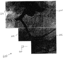
実施の一形態では、X線制御システム120はズーム機能を含む。オペレータが2回以上のX線照射を処理した後は、オペレータはズームアウト機能を使用して当該の点において受け取ったX線画像の合成にあたる画像を表示させることができる。こうした合成画像600の一例を図6aに示す。図6aに示す合成画像600では、画像602、604、606及び608は、ある順序で採取されたものである。オペレータは合成画像600を表示させ、この画像を使用して次の照射の位置610を選択する。行われた選択が図6aに示すように表示のない四半分である場合には、X線ガントリ130及び/またはテーブル140はこれに相当する位置まで動かされる。(しかし、実施の一形態では、表示のない四半分の全体に及ぶ画像を作成するためには、選択される位置は表示のない四半分の中心でなければならない。)
位置610を選択した後、照射が行われ、図6bに示す画像612などの画像が作成される。オペレータはズームアウト機能を使用して画像602、604、606、608及び614の各々からの寄与を含んだ新たな合成画像614を表示させることができる。領域の重なりは、標準的な画像処理方法を使用して合成させる。
【0023】
図4a〜b、5a〜b、6a〜cに示す例では、その空間的距離はオペレータが選択した点に基づいてX線制御システム120により決定されるので、X線ガントリ130またはテーブル140、あるいはこの両方を移動させている間はX線透視は必要がない。このため、オペレータと患者の両者に対するX線被曝線量が大幅に減少する。
【0024】
図7に示すブロック図はX線システム100の別の実施形態を表したものである。システム100に関するブロックの各々は、凡例705で示すように1つまたは複数の働きを実行する。図7に示す実施形態では、システム100はシステム・コントローラ710と、入出力システム715と、位置決め装置720と、画像処理装置725と、画像収集システム730と、X線発生システム735とを含む。システム・コントローラ710は、制御線702及びデータ線703を使用して、位置決め装置720、画像処理装置725、画像収集システム730及びX線発生システム735の各々を制御している。画像収集システム730はX線発生システム735が発生させたX線を受け取り、受け取ったX線を表すデータを画像処理装置725に伝送する。画像処理装置725は表示装置を含んでいる。画像処理装置725は、画像収集システム730から受け取ったデータに基づき画像を作成し、この画像をその表示装置上に表示させる。オペレータは、表示装置上に表示された画像内で1つの位置を選択し、この選択した位置に関する情報をシステム・コントローラ710に伝送する。システム・コントローラ710はオペレータから受け取った情報を処理し、位置決め装置720に対し、X線源を基準として患者を所望に位置決めするように指令する。こうした実施の一形態では、線源及び受信体が患者の周りを移動している間、患者は静止の状態に保たれる。別の実施形態では、静止しているX線源に対してそのテーブルを移動させる。さらに別の実施形態では、次の照射に対する位置決めの間に、患者を保持しているテーブルとX線源の両方が移動する。
【0025】
図7に示す実施の形態では、入出力システム715を用いてサービス・ツールへ、外部ネットワークへ、あるいは外部モニタへの接続を行う。システム・コントローラ710内で取り込まれた画像は、システム715に移出することができ、このシステム715において、これらの画像は、ネットワークを経た伝送、サービス・ツールによる読み取り、あるいは外部表示デバイス上への表示が可能となる。
【0026】
X線システム100の別の実施形態のブロック詳細図を図8に示す。実施の一形態では、X線システム100は、システム・キャビネット902、外部ビデオ・キャプチャ及びビデオ表示デバイス904、サービス・ツール906、外部ネットワーク・インタフェース908、2つのX線源930及び932、表示装置934、並びに各種のデータ取り込み及び患者位置決め制御機構を含んでいる。
【0027】
実施の一形態では、関連した構造あるいは流れ(以下、オブジェクトと呼ぶ)に関する状態または動きの変化を知るために、画像に対しリアルタイムで検討を加える。実施の一形態では、関連した構造あるいは流れに関する状態または動きの変化を知るための画像に対する検討にあたりパターン認識を利用する。オブジェクトについての画像自体から得られた情報は、その画像内の位置(さらにこうした実施の一形態では、その患者内の位置)と対応付けされる。そのオブジェクトの画像内の相対的位置が変化した場合には、この変化をX線制御システムにより自動的に追跡する。
【0028】
こうした実施の一形態では、制御ロジックを用いてオブジェクトを追跡し、X線源に対する患者の相対的位置を変更し、オブジェクトに追随させる(例えば、テーブルを移動させオブジェクトを中心の位置に維持させる)。さらに、制御ロジックを用いてX線のサイズ及び線量を変更することができる(例えば、画像のサイズを小さくし、これにより患者の被曝線量を低減させるようにコリメートすることができる)。
【0029】
こうした実施の一形態では、オブジェクトをハイライト(強調)表示させて、周囲の解剖構造からそのオブジェクトを際立たせる表示方法を用いている(例えば、ある色を用いてカテーテルの先端を表現し、また別の色を用いて血管壁を表現する)。
【0030】
軍事産業や運輸業では、ディジタル画像内で動きのあるオブジェクト及び静止しているオブジェクトの双方を特定することに関連した新たな技術が開発されてきた。こうした機能増強はさらにマスメディアにも及んでいる。マスメディアでは、高速で動くオブジェクト(例えば、ホッケーのパック)をリアルタイムで追跡し、色により強調表示することにより、観察者はオブジェクトをより緊密に追跡することができる。医療産業では、コンピュータ支援検出法により潜在的な乳腺腫瘍を特定できることが実証されている。しかしながら、こうした検出法はリルタイムではなくオフラインで実施されている。現在では、X線画像が高分解能のディジタル・フォーマットで作成されているため、そのディジタル画像内に含まれる情報をX線制御システムへの入力として用いて、その操作の挙動を変更しうる見込みがある。
【0031】
上記のように、画像データの自動的フィードバック及び制御を使用することによる潜在的な恩恵としては、処置が高速であること、X線処置の間のオペレータの関与が減ること、オペレータ及び患者に対する被曝線量が減少することなどがある。
【0032】
実施の一形態では、塞栓処置中に医師がカテーテルを脚部に挿入する間、X線制御システム120はカテーテルの先端を自動的に追尾する。カテーテルの先端は正確に画像内の中央にくるようにすることができ、あるいはカテーテルの先端は画像の辺縁から一定の距離だけ離した位置とすることができる。画像データのフィードバックを用いて、X線画像の数、サイズ及び持続時間を低減することができる。
【0033】
第2の実施形態では、X線制御システム120は、体内に注入された造影剤が主要動脈内の血管を通過して流れる間に、この造影剤を自動的に追尾する。こうした実施の一形態では、画像のサイズは維持され、このため患者への放射線被曝線量は制限される。こうした実施の一形態では、ボーラス(bolus) の位置に関する情報をX線制御システム120に対する入力として使用することにより、必要となる画像の枚数及びサイズが低減される。
【0034】
第3の実施形態では、X線画像内の皮膚、臓器または骨を認識し、かつ解剖学的関係を利用して重複を防止することにより、X線システム120はX線透視において重複回避技法を強化している。こうしたアプローチにより、特に上記の自動追跡の間において、患者と検出器の間をより短い距離に維持することができる。
【0035】
第4の実施形態では、X線システム120はカテーテル挿入の際にその先端の色を変更し、オペレータがより容易にその位置を特定できるようにしている。
【0036】
X線システム100の利点の一つは、オペレータまたは制御システムが以前のX線照射に含まれる画像情報に基づいて次のX線照射の位置を対話式に選択することができることである。さらに、本発明のX線制御システムでは、放射線被曝線量が低減されるようなX線の位置がより正確に決定される。実施の一形態では、X線透視の使用は完全に不要となる。さらに、X線照射位置を正確にすることにより、撮影領域(FOV)を狭くすることが見込まれ、さらにX線照射を低下させると同時に画質を向上させることができる。
【0037】
したがって、X線システム100により幾つかの全体的な恩恵が得られる。X線透視の使用が少なくなると、オペレータ及び患者に対する全体の放射線被曝線量が減少する。次のX線照射位置が正確であるため医学的X線処置が高速となり、さらに患者及びオペレータに対する全体の放射線被曝線量が減少する。最後に、医学的X線処置において使用するFOVがより狭くなることにより、X線システム100により放射線被曝線量を減少させながら画質を向上させることができる。
【0038】
本明細書に、具体的な実施形態を図示し記載してきたが、同じ目的を達成するために調整された任意の配置により例示した具体的な実施形態に代えることが可能であることは、通常の当業者であれば理解するであろう。本出願は本発明に関する任意の適用または変形形態の範囲に及ぶように意図したものである。したがって、本発明は、本特許請求の範囲及び本発明の等価物によって限定されるように意図したものである。
【図面の簡単な説明】
【図1】X線制御システムの実施の一形態を表したブロック図である。
【図2】図1に示すX線制御システムについての方法の実施の一形態を表した流れ図である。
【図3】図2に従ったX線制御システムについての方法に関する実施の一形態の流れ図である。
【図4a】新たなX線照射を選択するための選択処理に関する実施の一形態を表した図である。
【図4b】新たなX線照射を選択するための選択処理に関する実施の一形態を表した図である。
【図5a】新たなX線照射を選択するための選択処理に関する別の実施形態を表した図である。
【図5b】新たなX線照射を選択するための選択処理に関する別の実施形態を表した図である。
【図6a】ズーム機能を表した図である。
【図6b】ズーム機能を表した図である。
【図6c】ズーム機能を表した図である。
【図7】図2の別の実施形態を表すブロック図である。
【図8a】図7のブロック図に従ったX線システムの詳細図である。
【図8b】図7のブロック図に従ったX線システムの詳細図である。
【符号の説明】
100 X線システム
110 表示デバイス
120 X線制御システム
122 ユーザ入力
130 X線ガントリ
132 X線発生装置
140 テーブル
142 X線センサ
702 制御線
703 データ線
710 システム・コントローラ
715 入出力システム
720 位置決め装置
725 画像処理装置
730 画像収集システム
735 X線発生システム
902 システム・キャビネット
904 外部ビデオ・キャプチャ及びビデオ表示デバイス
906 サービス・ツール
908 外部ネットワーク・インタフェース
930 X線源
932 X線源
934 表示装置[0001]
BACKGROUND OF THE INVENTION
The present invention relates to medical imaging and, more particularly, to a system and method for positioning and acquiring an acquisition device based on image data.
[0002]
[Prior art]
Currently, medical X-ray procedures such as fluoroscopy use high data collection rates (velocities) for X-ray images. The image created by fluoroscopy is then used to manually guide the tool through an internal structure of an opaque object or object (eg, the human body). Guiding such a tool (eg, a medical device such as a catheter) through an opaque object is usually very inefficient and inaccurate. This is because it relies on operators of fluoroscopic devices and equipment to manually estimate the next position using various types of control techniques developed for this purpose. is there. X-ray fluoroscopy is used for interventional medical procedures such as balloon angioplasty and neuroembolization. These medical procedures are extremely successful and widely used. As a result of such extensive use, fluoroscopy has accounted for more than half of the diagnostic X-ray exposure dose. However, as a result of this widespread use, literature on serious skin damage has been found.
[0003]
One way to reduce patient and operator radiation exposure is to optimize the x-ray image acquisition and filtering techniques used for fluoroscopy. In one of these approaches, a command is given to the fluoroscopic device by using a combination of lowering the data collection rate of fluoroscopy and increasing the resolution of the X-ray image. However, this approach relies on a human operator to manually control the x-ray equipment and thus involves uncertainty.
[0004]
To date, no solution exists to address this uncertainty introduced by the operator manually controlling the fluoroscopic equipment. On the contrary, solutions sought in the medical industry either increase the resolution of the fluoroscopy device by increasing the image resolution or reduce the number of noisy images created by the fluoroscopy device. Therefore, it is limited to any one of reducing the radiation dose to the operator and the patient.
[0005]
[Problems to be solved by the invention]
What is needed is an X-ray control for interactively processing a selected point for an X-ray exposure based on the previous X-ray exposure to improve the efficiency and safety of medical X-ray treatment. Systems, devices and methods.
[0006]
[Means for Solving the Problems]
In accordance with one aspect of the present invention, X-ray systems and methods are provided for use in medical applications to complement or replace fluoroscopy. The X-ray system includes a display device, a gantry having an X-ray generator, a table having an X-ray sensor, and an X-ray control system connected to the display device, the gantry and the table. The X-ray control system includes a user input for indicating the position of the next X-ray irradiation. The X-ray control system receives X-ray data from the sensor, processes this data to form an X-ray image, displays the X-ray image on a display device, and makes the X-ray generator an X-ray sensor. Shift against. The amount and direction to shift is accurately determined using data from previous X-ray images.
[0007]
According to another aspect of the invention, a system and method for positioning an X-ray generator relative to an X-ray sensor is provided. An X-ray image is formed by receiving and processing the X-ray data from the sensor. The X-ray image is displayed on the display device, and one position is selected on the X-ray image. The X-ray generator is shifted relative to the X-ray sensor as a function of this position selected on the X-ray image.
[0008]
In accordance with yet another aspect of the invention, a system and method for tracking a first object within a second object is provided. X-rays are projected to pass through the second object in the vicinity of the first object, captured, and used to create a display image. This display image is displayed. The appearance of the first object is emphasized in the second object, the movement of the first object in the second object is detected, and the relative position of the second object with respect to the X-ray source is It is changed as a function of the movement of the first object before the display image is acquired.
[0009]
The x-ray control system, device and method utilize a computing system to determine a new position of the fluoroscopic instrument based on information processed from previous x-ray images. For this reason, the uncertainty introduced by the operator manually controlling the fluoroscopic equipment can be reduced. Furthermore, since the position of the next irradiation is controlled by the X-ray control system, the irradiation position becomes more accurate. Such an approach is in contrast to current fluoroscopy techniques that rely on the operator to manually guide the fluoroscopy instrument. Furthermore, by accurately guiding the fluoroscopic equipment, the radiation dose for both the operator and the patient is reduced.
[0010]
DETAILED DESCRIPTION OF THE INVENTION
In the following detailed description of the preferred embodiments, reference is made to the accompanying drawings that form a part hereof, and in which are shown by way of illustration specific embodiments in which the invention may be practiced. It should be understood that other embodiments may be utilized and structural changes may be made without departing from the scope of the present invention.
[0011]
Each part of the detailed description below represents the operations on data bits in the memory of a computer in terms of algorithms and symbolic representations. These algorithmic form descriptions and representations are the means used by those skilled in the data processing arts to most effectively convey the substance of their work to others skilled in the art. Each of the algorithms is a consistent sequence of steps that lead to the desired result. These steps include those requiring physical manipulations on physical quantities. Usually, though not necessarily, these quantities take the form of electrical or magnetic signals capable of being stored, transmitted, combined, compared, and otherwise manipulated. It has been found that these signals may be conveniently referred to as bits, values, elements, symbols, characters, terms, numbers, etc. primarily by convention. However, it should be noted that all of these terms and similar terms should be associated with the physical quantities in question, and these terms rarely become a convenient label for these quantities. As will be clear from the following discussion, unless otherwise specifically stated, the terms “processing”, “computing”, “calculating”, “determining” are used throughout the present invention. The description using terms such as “determining” and “displaying” refers to the operation and processing of a computer system or similar electronic computing device, and by these computer systems, the computer system Data that is represented as physical quantities (electronic quantities) in the registers and memories of a computer is manipulated and represented as similar physical quantities in the computer system's memory or registers or this type of information storage, transmission, or display device Is converted to another data.
[0012]
An
[0013]
The
[0014]
In one embodiment, the
[0015]
The block diagram shown in FIG. 2 represents one
[0016]
Another
[0017]
Control transfers to step 315, where an image representing the capture of the first exposure is displayed to the operator. Control then passes to step 320 where the
[0018]
In
[0019]
In one embodiment, X-rays are stopped while the
[0020]
Images representing successive successive X-ray image acquisitions are shown in FIGS. 4a and 4b, FIGS. 5a and 5b, and FIGS. In the examples shown in FIGS. 4a and 4b, FIGS. 5a and 5b, and FIGS. In the embodiment shown in FIGS. 4 a-b, the
[0021]
In the example shown in FIGS. 5a and 5b, a
[0022]
In one embodiment, the
After selecting the position 610, irradiation is performed and an image such as the
[0023]
In the example shown in FIGS. 4a-b, 5a-b, 6a-c, the spatial distance is determined by the
[0024]
The block diagram shown in FIG. 7 represents another embodiment of the
[0025]
In the embodiment shown in FIG. 7, an input /
[0026]
A detailed block diagram of another embodiment of the
[0027]
In one embodiment, the image is examined in real time in order to know changes in state or motion with respect to the associated structure or flow (hereinafter referred to as an object). In one embodiment, pattern recognition is used to examine an image to know changes in state or motion related to the structure or flow. Information about the object obtained from the image itself is associated with a position in the image (and in that embodiment, a position within the patient). If the relative position of the object in the image changes, this change is automatically tracked by the X-ray control system.
[0028]
In one such embodiment, control logic is used to track the object, change the patient's relative position with respect to the x-ray source, and follow the object (e.g., move the table and keep the object in the center position). . In addition, control logic can be used to change the size and dose of the x-ray (eg, collimate to reduce the size of the image and thereby reduce the patient dose).
[0029]
One such embodiment uses a display method that highlights an object and highlights the object from the surrounding anatomy (eg, using a certain color to represent the tip of the catheter, Use different colors to represent the vessel wall).
[0030]
In the military and transportation industries, new technologies have been developed that relate to identifying both moving and stationary objects in digital images. These enhancements extend to the mass media. In mass media, tracking fast moving objects (eg, hockey pucks) in real time and highlighting them with colors allows the observer to track the objects more closely. The medical industry has demonstrated that computer aided detection can identify potential breast tumors. However, such detection methods are performed off-line rather than in real time. Currently, X-ray images are created in a high-resolution digital format, so the information contained in the digital images can be used as input to the X-ray control system to change the behavior of the operation. is there.
[0031]
As noted above, the potential benefits of using automatic feedback and control of image data include faster procedures, reduced operator involvement during x-ray procedures, exposure to operators and patients. The dose may decrease.
[0032]
In one embodiment, the
[0033]
In the second embodiment, the
[0034]
In a third embodiment, by recognizing skin, organs or bones in an x-ray image and utilizing anatomical relationships to prevent duplication, the
[0035]
In the fourth embodiment, the
[0036]
One advantage of the
[0037]
Thus, the
[0038]
Although specific embodiments have been illustrated and described herein, it is generally possible to substitute for the specific embodiments illustrated by any arrangement adjusted to achieve the same purpose. Those skilled in the art will understand. This application is intended to cover any extent of application or variation that is related to the present invention. Therefore, it is intended that this invention be limited by the claims and the equivalents of this invention.
[Brief description of the drawings]
FIG. 1 is a block diagram showing an embodiment of an X-ray control system.
FIG. 2 is a flow chart illustrating an embodiment of a method for the X-ray control system shown in FIG.
FIG. 3 is a flow diagram of one embodiment of a method for an X-ray control system according to FIG.
FIG. 4a is a diagram showing an embodiment relating to a selection process for selecting a new X-ray irradiation.
FIG. 4b is a diagram showing an embodiment relating to a selection process for selecting a new X-ray irradiation.
FIG. 5a is a diagram illustrating another embodiment relating to a selection process for selecting a new X-ray exposure.
FIG. 5b is a diagram illustrating another embodiment relating to a selection process for selecting a new X-ray exposure.
FIG. 6a is a diagram illustrating a zoom function.
FIG. 6B is a diagram illustrating a zoom function.
FIG. 6c is a diagram illustrating a zoom function.
FIG. 7 is a block diagram illustrating another embodiment of FIG.
8a is a detailed view of the X-ray system according to the block diagram of FIG.
8b is a detailed view of the X-ray system according to the block diagram of FIG.
[Explanation of symbols]
100 X-ray system
110 Display device
120 X-ray control system
122 User input
130 X-ray gantry
132 X-ray generator
140 tables
142 X-ray sensor
702 Control line
703 data line
710 System controller
715 I / O system
720 Positioning device
725 Image processing apparatus
730 Image acquisition system
735 X-ray generation system
902 System cabinet
904 External video capture and video display device
906 Service Tool
908 External network interface
930 X-ray source
932 X-ray source
934 display device
Claims (10)
前記X線発生装置が前記X線センサに対してシフトする間は、X線が停止されることを特徴とするX線システム。A display device, a gantry having an X-ray generator, a table having an X-ray sensor, and an X-ray control system connected to the display device, the gantry and the table, receiving X-ray data from the sensor Processing the data to form an X-ray image, causing the X-ray image to be displayed on the display device, and the X as a function of a position selected outside the X-ray image on the display device. An X-ray control system that shifts the X-ray generator with respect to the X-ray sensor ,
X-ray system while the X-rays, characterized in Rukoto stopped to the X-ray generator is shifted relative to the X-ray sensor.
X線画像を表すデータを含む表示画像を表示デバイス上に表示するステップと、
前記表示デバイス上の前記表示画像の外の1つの位置を選択するステップと、
前記表示画像の外で選択した前記位置の関数として前記X線発生装置を前記X線センサに対してシフトさせるステップと、
を含み、
前記シフトする間は、X線が停止されることを特徴とするコンピュータ読み取り可能な媒体。An X-ray system having an X-ray generator and an X-ray sensor, wherein the computer-readable medium includes program code for performing a method of positioning the X-ray generator with respect to the X-ray sensor, The method comprises
Displaying a display image including data representing an X-ray image on a display device;
Selecting a position outside the display image on the display device;
Shifting the X-ray generator relative to the X-ray sensor as a function of the position selected outside the display image;
Only including,
A computer readable medium wherein X-rays are stopped during the shift .
Applications Claiming Priority (2)
| Application Number | Priority Date | Filing Date | Title |
|---|---|---|---|
| US09/418167 | 1999-10-13 | ||
| US09/418,167 US6463121B1 (en) | 1999-10-13 | 1999-10-13 | Interactive x-ray position and exposure control using image data as reference information |
Publications (3)
| Publication Number | Publication Date |
|---|---|
| JP2001149356A JP2001149356A (en) | 2001-06-05 |
| JP2001149356A5 JP2001149356A5 (en) | 2007-11-22 |
| JP4590084B2 true JP4590084B2 (en) | 2010-12-01 |
Family
ID=23657000
Family Applications (1)
| Application Number | Title | Priority Date | Filing Date |
|---|---|---|---|
| JP2000312785A Expired - Lifetime JP4590084B2 (en) | 1999-10-13 | 2000-10-13 | Method and system for positioning an X-ray generator relative to an X-ray sensor |
Country Status (4)
| Country | Link |
|---|---|
| US (1) | US6463121B1 (en) |
| EP (1) | EP1092391B1 (en) |
| JP (1) | JP4590084B2 (en) |
| DE (1) | DE60034749T2 (en) |
Families Citing this family (97)
| Publication number | Priority date | Publication date | Assignee | Title |
|---|---|---|---|---|
| US6568851B2 (en) * | 2000-10-25 | 2003-05-27 | Kabushiki Kaisha Toshiba | X-ray CT scanner |
| JP3926120B2 (en) * | 2001-02-16 | 2007-06-06 | 株式会社モリタ製作所 | X-ray imaging position setting means for an object, and X-ray imaging apparatus provided with this means |
| DE10108298A1 (en) * | 2001-02-21 | 2002-09-26 | Sirona Dental Systems Gmbh | Arrangement and method for positioning a digital X-ray device |
| DE10109754B4 (en) * | 2001-02-28 | 2004-12-09 | Siemens Ag | Universal x-ray machine |
| WO2002082125A1 (en) * | 2001-04-03 | 2002-10-17 | L-3 Communications Security & Detection Systems | X-ray inspection system |
| US6907103B2 (en) * | 2002-06-19 | 2005-06-14 | Agilent Technologies, Inc. | Capturing images of moving objects with a moving illumination point source |
| GB0216893D0 (en) * | 2002-07-20 | 2002-08-28 | Univ Surrey | Image colouring |
| US6925149B2 (en) * | 2002-07-30 | 2005-08-02 | Siemens Medical Solutions Usa, Inc. | Radiation imaging system |
| US6922462B2 (en) * | 2002-07-31 | 2005-07-26 | Ge Medical Systems Global Technology Company, Llc | Method, system and computer product for plaque characterization |
| US6944265B2 (en) | 2002-11-25 | 2005-09-13 | Ge Medical Systems Global Technology Company, Llc | Image pasting using geometry measurement and a flat-panel detector |
| US6895076B2 (en) | 2003-06-03 | 2005-05-17 | Ge Medical Systems Global Technology Company, Llc | Methods and apparatus for multiple image acquisition on a digital detector |
| US20050238140A1 (en) * | 2003-08-20 | 2005-10-27 | Dan Hardesty | X-ray imaging system with automatic image resolution enhancement |
| US20060241370A1 (en) * | 2005-03-30 | 2006-10-26 | George Kramp | Medical x-ray imaging workflow improvement |
| US7133492B2 (en) * | 2004-03-30 | 2006-11-07 | Siemens Medical Solutions Usa, Inc. | Method for reducing radiation exposure during patient positioning |
| JP3912606B2 (en) * | 2004-10-26 | 2007-05-09 | 株式会社リガク | X-ray thin film inspection apparatus, thin film inspection apparatus for product wafer and method thereof |
| DE102004059663A1 (en) * | 2004-12-10 | 2006-06-29 | Siemens Ag | Method for multidimensional imaging involves multi-row computer tomographs for scanning patient whereby scan speed is adjusted according to the propagation speed of contrast agent in scanning direction |
| US20070036266A1 (en) * | 2005-03-29 | 2007-02-15 | George Kramp | Medical x-ray imaging workflow improvement |
| US7639782B2 (en) * | 2005-08-23 | 2009-12-29 | Ge Medical Systems Israel, Ltd. | Methods and systems for automatic patient table positioning |
| US8784336B2 (en) | 2005-08-24 | 2014-07-22 | C. R. Bard, Inc. | Stylet apparatuses and methods of manufacture |
| CA2622227A1 (en) * | 2005-09-14 | 2007-03-22 | Koninklijke Philips Electronics N.V. | Low-dose iso-centering |
| JP4810182B2 (en) * | 2005-10-17 | 2011-11-09 | キヤノン株式会社 | Radiography equipment |
| US8388546B2 (en) | 2006-10-23 | 2013-03-05 | Bard Access Systems, Inc. | Method of locating the tip of a central venous catheter |
| US7794407B2 (en) | 2006-10-23 | 2010-09-14 | Bard Access Systems, Inc. | Method of locating the tip of a central venous catheter |
| US7529336B2 (en) | 2007-05-31 | 2009-05-05 | Test Research, Inc. | System and method for laminography inspection |
| JP5464799B2 (en) * | 2007-11-16 | 2014-04-09 | キヤノン株式会社 | Image processing apparatus, image processing method, and program |
| US10524691B2 (en) | 2007-11-26 | 2020-01-07 | C. R. Bard, Inc. | Needle assembly including an aligned magnetic element |
| US8849382B2 (en) | 2007-11-26 | 2014-09-30 | C. R. Bard, Inc. | Apparatus and display methods relating to intravascular placement of a catheter |
| US9521961B2 (en) | 2007-11-26 | 2016-12-20 | C. R. Bard, Inc. | Systems and methods for guiding a medical instrument |
| US10449330B2 (en) | 2007-11-26 | 2019-10-22 | C. R. Bard, Inc. | Magnetic element-equipped needle assemblies |
| US9649048B2 (en) | 2007-11-26 | 2017-05-16 | C. R. Bard, Inc. | Systems and methods for breaching a sterile field for intravascular placement of a catheter |
| US10751509B2 (en) | 2007-11-26 | 2020-08-25 | C. R. Bard, Inc. | Iconic representations for guidance of an indwelling medical device |
| US8781555B2 (en) | 2007-11-26 | 2014-07-15 | C. R. Bard, Inc. | System for placement of a catheter including a signal-generating stylet |
| ES2832713T3 (en) | 2007-11-26 | 2021-06-11 | Bard Inc C R | Integrated system for intravascular catheter placement |
| JP5550209B2 (en) * | 2007-12-25 | 2014-07-16 | キヤノン株式会社 | X-ray equipment |
| US8478382B2 (en) | 2008-02-11 | 2013-07-02 | C. R. Bard, Inc. | Systems and methods for positioning a catheter |
| JP5305747B2 (en) * | 2008-06-17 | 2013-10-02 | キヤノン株式会社 | Radiation image capturing apparatus, driving method thereof, and program |
| US8175684B2 (en) * | 2008-07-29 | 2012-05-08 | General Electric Company | Method for processing images and associated medical imaging system |
| EP2313143B1 (en) | 2008-08-22 | 2014-09-24 | C.R. Bard, Inc. | Catheter assembly including ecg sensor and magnetic assemblies |
| JP4693884B2 (en) * | 2008-09-18 | 2011-06-01 | キヤノン株式会社 | Multi X-ray imaging apparatus and control method thereof |
| US8437833B2 (en) | 2008-10-07 | 2013-05-07 | Bard Access Systems, Inc. | Percutaneous magnetic gastrostomy |
| JP5313617B2 (en) * | 2008-10-15 | 2013-10-09 | 富士フイルム株式会社 | Radiation image detection device |
| JP2010213798A (en) * | 2009-03-13 | 2010-09-30 | Toshiba Corp | Cardiovascular x-ray diagnostic system |
| KR101773207B1 (en) | 2009-06-12 | 2017-08-31 | 바드 액세스 시스템즈, 인크. | Catheter tip positioning method |
| US9445734B2 (en) | 2009-06-12 | 2016-09-20 | Bard Access Systems, Inc. | Devices and methods for endovascular electrography |
| US9532724B2 (en) | 2009-06-12 | 2017-01-03 | Bard Access Systems, Inc. | Apparatus and method for catheter navigation using endovascular energy mapping |
| US7934869B2 (en) * | 2009-06-30 | 2011-05-03 | Mitsubishi Electric Research Labs, Inc. | Positioning an object based on aligned images of the object |
| AU2010300677B2 (en) | 2009-09-29 | 2014-09-04 | C.R. Bard, Inc. | Stylets for use with apparatus for intravascular placement of a catheter |
| US11103213B2 (en) | 2009-10-08 | 2021-08-31 | C. R. Bard, Inc. | Spacers for use with an ultrasound probe |
| JP2013518676A (en) | 2010-02-02 | 2013-05-23 | シー・アール・バード・インコーポレーテッド | Apparatus and method for locating catheter navigation and tip |
| US10524741B2 (en) | 2010-03-31 | 2020-01-07 | Koninklijke Philips N.V. | Automated identification of an anatomy part |
| EP2575610B1 (en) | 2010-05-28 | 2022-10-05 | C. R. Bard, Inc. | Insertion guidance system for needles and medical components |
| EP2575611B1 (en) | 2010-05-28 | 2021-03-03 | C. R. Bard, Inc. | Apparatus for use with needle insertion guidance system |
| AU2011289513B2 (en) | 2010-08-09 | 2014-05-29 | C.R. Bard, Inc. | Support and cover structures for an ultrasound probe head |
| MX338127B (en) | 2010-08-20 | 2016-04-04 | Bard Inc C R | Reconfirmation of ecg-assisted catheter tip placement. |
| US8526700B2 (en) | 2010-10-06 | 2013-09-03 | Robert E. Isaacs | Imaging system and method for surgical and interventional medical procedures |
| US11231787B2 (en) | 2010-10-06 | 2022-01-25 | Nuvasive, Inc. | Imaging system and method for use in surgical and interventional medical procedures |
| US9785246B2 (en) | 2010-10-06 | 2017-10-10 | Nuvasive, Inc. | Imaging system and method for use in surgical and interventional medical procedures |
| US8801693B2 (en) | 2010-10-29 | 2014-08-12 | C. R. Bard, Inc. | Bioimpedance-assisted placement of a medical device |
| US20120155609A1 (en) * | 2010-12-20 | 2012-06-21 | General Electric Company | System and method of low dose exposure aided positioning (leap) for digital radiography |
| JP5579636B2 (en) * | 2011-02-07 | 2014-08-27 | 富士フイルム株式会社 | Radiographic imaging apparatus and radiographic imaging method |
| EP2688632B1 (en) * | 2011-03-22 | 2016-05-18 | Corindus Inc. | Robotic catheter system including imaging system control |
| JP6008960B2 (en) | 2011-07-06 | 2016-10-19 | シー・アール・バード・インコーポレーテッドC R Bard Incorporated | Needle length determination and calibration for insertion guidance systems |
| USD699359S1 (en) | 2011-08-09 | 2014-02-11 | C. R. Bard, Inc. | Ultrasound probe head |
| USD724745S1 (en) | 2011-08-09 | 2015-03-17 | C. R. Bard, Inc. | Cap for an ultrasound probe |
| US9480440B2 (en) | 2011-09-28 | 2016-11-01 | Qr Srl | System and method for cone beam computed tomography |
| WO2013070775A1 (en) | 2011-11-07 | 2013-05-16 | C.R. Bard, Inc | Ruggedized ultrasound hydrogel insert |
| DE102012005899A1 (en) * | 2012-03-15 | 2013-09-19 | Fraunhofer-Gesellschaft zur Förderung der angewandten Forschung e.V. | Detector arrangement for taking X-ray images of an object to be imaged |
| JP6112773B2 (en) * | 2012-04-17 | 2017-04-12 | キヤノン株式会社 | Radiation imaging apparatus, control method thereof, and program |
| GB2501891B (en) * | 2012-05-09 | 2016-08-03 | Original Design Services Ltd | Radiography imaging system |
| US10820885B2 (en) | 2012-06-15 | 2020-11-03 | C. R. Bard, Inc. | Apparatus and methods for detection of a removable cap on an ultrasound probe |
| JP6176832B2 (en) * | 2013-04-18 | 2017-08-09 | 東芝メディカルシステムズ株式会社 | Support device and X-ray diagnostic apparatus |
| KR102105853B1 (en) * | 2013-07-26 | 2020-05-04 | 삼성전자주식회사 | X-ray stitching jig |
| US9554759B2 (en) * | 2013-09-18 | 2017-01-31 | Carestream Health, Inc. | Digital radiography detector image readout process |
| US20160296182A1 (en) * | 2013-11-19 | 2016-10-13 | Scanflex Healthcare AB | Flat panel x-ray imaging device - twin dual control gui |
| WO2015120256A2 (en) | 2014-02-06 | 2015-08-13 | C.R. Bard, Inc. | Systems and methods for guidance and placement of an intravascular device |
| JP6400307B2 (en) * | 2014-03-10 | 2018-10-03 | キヤノンメディカルシステムズ株式会社 | X-ray diagnostic imaging equipment |
| US9420976B2 (en) * | 2014-03-19 | 2016-08-23 | General Electric Company | Systems and methods for optimized source collimation |
| TWI535421B (en) * | 2014-05-14 | 2016-06-01 | Automatic identification and adjustment of the selected parts of the medical equipment | |
| JP2016034451A (en) * | 2014-08-04 | 2016-03-17 | 株式会社東芝 | X-ray diagnostic apparatus |
| WO2016042926A1 (en) * | 2014-09-19 | 2016-03-24 | 日本電気株式会社 | Image processing device, image processing method, and program |
| JP2016059739A (en) * | 2014-09-22 | 2016-04-25 | 富士フイルム株式会社 | Portable console, control method for portable console, program for portable console, and radiographic system |
| JP6122410B2 (en) * | 2014-09-22 | 2017-04-26 | 富士フイルム株式会社 | Portable console, portable console control method, portable console program, and radiation imaging system |
| US10973584B2 (en) | 2015-01-19 | 2021-04-13 | Bard Access Systems, Inc. | Device and method for vascular access |
| JP6072096B2 (en) * | 2015-01-30 | 2017-02-01 | キヤノン株式会社 | Radiation imaging system, control method, control method, and program |
| JP6072102B2 (en) * | 2015-01-30 | 2017-02-01 | キヤノン株式会社 | Radiographic system and radiographic method |
| JP6072097B2 (en) * | 2015-01-30 | 2017-02-01 | キヤノン株式会社 | Radiation imaging apparatus, control apparatus, long imaging system, control method, and program |
| WO2016210325A1 (en) | 2015-06-26 | 2016-12-29 | C.R. Bard, Inc. | Connector interface for ecg-based catheter positioning system |
| US10383590B2 (en) * | 2015-09-28 | 2019-08-20 | General Electric Company | Methods and systems for adaptive scan control |
| US11000207B2 (en) | 2016-01-29 | 2021-05-11 | C. R. Bard, Inc. | Multiple coil system for tracking a medical device |
| DE102016205176A1 (en) * | 2016-03-30 | 2017-10-05 | Siemens Healthcare Gmbh | Apparatus and method for creating an X-ray panoramic image |
| CN106725570B (en) | 2016-12-30 | 2019-12-20 | 上海联影医疗科技有限公司 | Imaging method and system |
| JP6885803B2 (en) * | 2017-06-27 | 2021-06-16 | ゼネラル・エレクトリック・カンパニイ | Radiation imaging device and imaging method |
| WO2019019048A1 (en) * | 2017-07-26 | 2019-01-31 | Shenzhen Xpectvision Technology Co., Ltd. | X-ray imaging system and method of x-ray image tracking |
| US11191504B2 (en) * | 2018-07-31 | 2021-12-07 | Canon Medical Systems Corporation | X-ray diagnosis apparatus comprising a blood vessel running information acquiring function, a position specification function, and a diaphragm control function |
| WO2020081373A1 (en) | 2018-10-16 | 2020-04-23 | Bard Access Systems, Inc. | Safety-equipped connection systems and methods thereof for establishing electrical connections |
| JP7169853B2 (en) * | 2018-11-09 | 2022-11-11 | キヤノン株式会社 | Image processing device, radiation imaging device, and image processing method |
| US10835196B2 (en) | 2019-01-24 | 2020-11-17 | General Electric Company | Method and systems for camera-aided x-ray imaging |
Citations (12)
| Publication number | Priority date | Publication date | Assignee | Title |
|---|---|---|---|---|
| US4609940A (en) * | 1983-08-24 | 1986-09-02 | Siemens Aktiengesellschaft | Radiodiagnostic installation with a patient table and a primary radiation diaphragm |
| JPH04215743A (en) * | 1990-02-02 | 1992-08-06 | Siemens Ag | Operation method and apparatus for x-ray inspector |
| JPH05504087A (en) * | 1990-11-14 | 1993-07-01 | シーダーズ―サイナイ・メディカル・センター | Display device that identifies the shape of coronary arteries |
| JPH06205771A (en) * | 1992-09-09 | 1994-07-26 | Picker Internatl Inc | Method and device to take picture of four dimensional spiral-form volume using fast sweep |
| JPH06217968A (en) * | 1992-10-23 | 1994-08-09 | General Electric Co <Ge> | Automatic displaying method for x-ray frame sequence and displaying method for x-ray frame sequence |
| JPH0822287B2 (en) * | 1986-11-14 | 1996-03-06 | ドルニエ、メディツィンテヒニク、ゲゼルシャフト、ミット、ベシュレンクテル、ハフツング | Positioning device that automatically positions the patient |
| JPH08166995A (en) * | 1994-12-13 | 1996-06-25 | Toshiba Corp | Medical diagnosis support system |
| JP2539148B2 (en) * | 1991-11-29 | 1996-10-02 | ゼネラル・エレクトリック・カンパニイ | Method and apparatus for reducing X-ray dose |
| JPH09276259A (en) * | 1996-02-16 | 1997-10-28 | Toshiba Corp | X-ray diagnostic device |
| JPH10179569A (en) * | 1996-12-27 | 1998-07-07 | Toshiba Corp | Medical image diagnostic device and monitor image display method |
| JPH10234714A (en) * | 1997-02-21 | 1998-09-08 | Toshiba Iyou Syst Eng Kk | X-ray radiographic device |
| DE19842950A1 (en) * | 1997-09-18 | 1999-03-25 | Siemens Corp Research Inc | Method for obtaining angiograms |
Family Cites Families (19)
| Publication number | Priority date | Publication date | Assignee | Title |
|---|---|---|---|---|
| DE3030332C2 (en) * | 1980-08-11 | 1983-04-07 | Siemens AG, 1000 Berlin und 8000 München | Primary radiation diaphragm for an X-ray examination device |
| DE3034933A1 (en) * | 1980-09-16 | 1982-04-22 | Siemens AG, 1000 Berlin und 8000 München | X-RAY DIAGNOSTIC SYSTEM WITH AT LEAST ONE X-RAY GENERATOR AND X-RAY DEVICES |
| US4926452A (en) | 1987-10-30 | 1990-05-15 | Four Pi Systems Corporation | Automated laminography system for inspection of electronics |
| US5396418A (en) * | 1988-10-20 | 1995-03-07 | Picker International, Inc. | Four dimensional spiral volume imaging using fast retrace |
| DE4005111A1 (en) * | 1990-02-17 | 1991-08-22 | Philips Patentverwaltung | X-RAY DIAGNOSTIC DEVICE WITH MEANS FOR THE ENLARGED VISUAL DISPLAY OF A SELECTABLE SECTION OF THE OVERALL IMAGE AREA |
| FR2664153B1 (en) * | 1990-07-06 | 1992-09-11 | Gen Electric Cgr | RADIODIAGNOSTIC SYSTEM FOR ANGIOGRAPHIC EXAMINATION WITH AUTOMATIC EMBLEM TRACKING DEVICE. |
| US5054045A (en) * | 1990-11-14 | 1991-10-01 | Cedars-Sinai Medical Center | Coronary tracking display |
| US5142557A (en) * | 1990-12-21 | 1992-08-25 | Photometrics Ltd. | CCD and phosphor screen digital radiology apparatus and method for high resolution mammography |
| US5211165A (en) * | 1991-09-03 | 1993-05-18 | General Electric Company | Tracking system to follow the position and orientation of a device with radiofrequency field gradients |
| US5289373A (en) * | 1991-11-29 | 1994-02-22 | General Electric Company | Method and apparatus for real-time tracking of catheter guide wires in fluoroscopic images during interventional radiological procedures |
| US5221283A (en) | 1992-05-15 | 1993-06-22 | General Electric Company | Apparatus and method for stereotactic surgery |
| DE4220282A1 (en) * | 1992-06-20 | 1993-12-23 | Philips Patentverwaltung | Peripheral angiography procedure and arrangement for performing the procedure |
| US5282254A (en) * | 1992-06-29 | 1994-01-25 | Siemens Corporate Research, Inc. | Method for locating an edge portion of an aperture in a filter member in X-ray fluoroscopy apparatus |
| US5369678A (en) * | 1992-06-29 | 1994-11-29 | Siemens Corporate Research, Inc. | Method for tracking a catheter probe during a fluoroscopic procedure |
| US5769640A (en) | 1992-12-02 | 1998-06-23 | Cybernet Systems Corporation | Method and system for simulating medical procedures including virtual reality and control method and system for use therein |
| US5886353A (en) * | 1995-04-21 | 1999-03-23 | Thermotrex Corporation | Imaging device |
| US5771310A (en) | 1996-12-30 | 1998-06-23 | Shriners Hospitals For Children | Method and apparatus for recording three-dimensional topographies |
| DE19728023A1 (en) * | 1996-07-12 | 1998-01-22 | Siemens Ag | X=ray diagnostic appts |
| WO1999030486A2 (en) * | 1997-12-10 | 1999-06-17 | Koninklijke Philips Electronics N.V. | Forming an assembled image from successive x-ray images |
-
1999
- 1999-10-13 US US09/418,167 patent/US6463121B1/en not_active Expired - Lifetime
-
2000
- 2000-10-11 EP EP00308929A patent/EP1092391B1/en not_active Expired - Lifetime
- 2000-10-11 DE DE60034749T patent/DE60034749T2/en not_active Expired - Lifetime
- 2000-10-13 JP JP2000312785A patent/JP4590084B2/en not_active Expired - Lifetime
Patent Citations (12)
| Publication number | Priority date | Publication date | Assignee | Title |
|---|---|---|---|---|
| US4609940A (en) * | 1983-08-24 | 1986-09-02 | Siemens Aktiengesellschaft | Radiodiagnostic installation with a patient table and a primary radiation diaphragm |
| JPH0822287B2 (en) * | 1986-11-14 | 1996-03-06 | ドルニエ、メディツィンテヒニク、ゲゼルシャフト、ミット、ベシュレンクテル、ハフツング | Positioning device that automatically positions the patient |
| JPH04215743A (en) * | 1990-02-02 | 1992-08-06 | Siemens Ag | Operation method and apparatus for x-ray inspector |
| JPH05504087A (en) * | 1990-11-14 | 1993-07-01 | シーダーズ―サイナイ・メディカル・センター | Display device that identifies the shape of coronary arteries |
| JP2539148B2 (en) * | 1991-11-29 | 1996-10-02 | ゼネラル・エレクトリック・カンパニイ | Method and apparatus for reducing X-ray dose |
| JPH06205771A (en) * | 1992-09-09 | 1994-07-26 | Picker Internatl Inc | Method and device to take picture of four dimensional spiral-form volume using fast sweep |
| JPH06217968A (en) * | 1992-10-23 | 1994-08-09 | General Electric Co <Ge> | Automatic displaying method for x-ray frame sequence and displaying method for x-ray frame sequence |
| JPH08166995A (en) * | 1994-12-13 | 1996-06-25 | Toshiba Corp | Medical diagnosis support system |
| JPH09276259A (en) * | 1996-02-16 | 1997-10-28 | Toshiba Corp | X-ray diagnostic device |
| JPH10179569A (en) * | 1996-12-27 | 1998-07-07 | Toshiba Corp | Medical image diagnostic device and monitor image display method |
| JPH10234714A (en) * | 1997-02-21 | 1998-09-08 | Toshiba Iyou Syst Eng Kk | X-ray radiographic device |
| DE19842950A1 (en) * | 1997-09-18 | 1999-03-25 | Siemens Corp Research Inc | Method for obtaining angiograms |
Also Published As
| Publication number | Publication date |
|---|---|
| US6463121B1 (en) | 2002-10-08 |
| EP1092391B1 (en) | 2007-05-09 |
| DE60034749T2 (en) | 2008-01-17 |
| DE60034749D1 (en) | 2007-06-21 |
| EP1092391A1 (en) | 2001-04-18 |
| JP2001149356A (en) | 2001-06-05 |
Similar Documents
| Publication | Publication Date | Title |
|---|---|---|
| JP4590084B2 (en) | Method and system for positioning an X-ray generator relative to an X-ray sensor | |
| JP6527210B2 (en) | Image display generation method | |
| EP2482726B1 (en) | Vascular roadmapping | |
| JP5269376B2 (en) | Image display apparatus and X-ray diagnostic treatment apparatus | |
| JP3667813B2 (en) | X-ray diagnostic equipment | |
| US9042628B2 (en) | 3D-originated cardiac roadmapping | |
| US8971601B2 (en) | Medical image diagnosis device and medical image processing method | |
| US20060082598A1 (en) | Medical image processing apparatus | |
| US20080125649A1 (en) | Automatic object tracking in a region of interest | |
| EP1599137A1 (en) | Intravascular imaging | |
| JPH08332191A (en) | Device and method for displaying three-dimensional image processing | |
| JP5259283B2 (en) | X-ray diagnostic apparatus and image processing program thereof | |
| US10188362B2 (en) | X-ray fluoroscopy and imaging apparatus | |
| JP5379960B2 (en) | 3D image processing apparatus and reconstruction area designation method | |
| CN112150543A (en) | Imaging positioning method, device and equipment of medical imaging equipment and storage medium | |
| DE102008032313B3 (en) | Medical device for navigating e.g. medical instrument, in heart and lung of patient during e.g. minimal invasive surgery, has system control for operating and controlling imaging medical device and positioning and navigation device | |
| JP5652994B2 (en) | X-ray diagnostic equipment | |
| EP2931127B1 (en) | Interventional system | |
| US8457720B2 (en) | Apparatus for assisting with the positioning of an implant | |
| JP2010240254A (en) | X-ray diagnostic apparatus | |
| JP2013066802A (en) | Image display device | |
| US20230148987A1 (en) | Interventional system | |
| JP7438834B2 (en) | Medical image processing equipment, X-ray diagnostic equipment and programs | |
| US20230190212A1 (en) | Actuation method for x-ray device and x-ray device | |
| US20080039719A1 (en) | Method for determining an optimal trigger time and device for ECG-triggered recording of an object |
Legal Events
| Date | Code | Title | Description |
|---|---|---|---|
| A521 | Request for written amendment filed |
Free format text: JAPANESE INTERMEDIATE CODE: A523 Effective date: 20071010 |
|
| A621 | Written request for application examination |
Free format text: JAPANESE INTERMEDIATE CODE: A621 Effective date: 20071010 |
|
| A131 | Notification of reasons for refusal |
Free format text: JAPANESE INTERMEDIATE CODE: A131 Effective date: 20091110 |
|
| A521 | Request for written amendment filed |
Free format text: JAPANESE INTERMEDIATE CODE: A523 Effective date: 20100208 |
|
| RD02 | Notification of acceptance of power of attorney |
Free format text: JAPANESE INTERMEDIATE CODE: A7422 Effective date: 20100208 |
|
| RD04 | Notification of resignation of power of attorney |
Free format text: JAPANESE INTERMEDIATE CODE: A7424 Effective date: 20100208 |
|
| A521 | Request for written amendment filed |
Free format text: JAPANESE INTERMEDIATE CODE: A523 Effective date: 20100302 |
|
| TRDD | Decision of grant or rejection written | ||
| A01 | Written decision to grant a patent or to grant a registration (utility model) |
Free format text: JAPANESE INTERMEDIATE CODE: A01 Effective date: 20100824 |
|
| A01 | Written decision to grant a patent or to grant a registration (utility model) |
Free format text: JAPANESE INTERMEDIATE CODE: A01 |
|
| A61 | First payment of annual fees (during grant procedure) |
Free format text: JAPANESE INTERMEDIATE CODE: A61 Effective date: 20100913 |
|
| R150 | Certificate of patent or registration of utility model |
Ref document number: 4590084 Country of ref document: JP Free format text: JAPANESE INTERMEDIATE CODE: R150 Free format text: JAPANESE INTERMEDIATE CODE: R150 |
|
| FPAY | Renewal fee payment (event date is renewal date of database) |
Free format text: PAYMENT UNTIL: 20130917 Year of fee payment: 3 |
|
| R250 | Receipt of annual fees |
Free format text: JAPANESE INTERMEDIATE CODE: R250 |
|
| R250 | Receipt of annual fees |
Free format text: JAPANESE INTERMEDIATE CODE: R250 |
|
| R250 | Receipt of annual fees |
Free format text: JAPANESE INTERMEDIATE CODE: R250 |
|
| R250 | Receipt of annual fees |
Free format text: JAPANESE INTERMEDIATE CODE: R250 |
|
| R250 | Receipt of annual fees |
Free format text: JAPANESE INTERMEDIATE CODE: R250 |
|
| R250 | Receipt of annual fees |
Free format text: JAPANESE INTERMEDIATE CODE: R250 |
|
| R250 | Receipt of annual fees |
Free format text: JAPANESE INTERMEDIATE CODE: R250 |
|
| R250 | Receipt of annual fees |
Free format text: JAPANESE INTERMEDIATE CODE: R250 |