JP4589397B2 - lamp - Google Patents
lamp Download PDFInfo
- Publication number
- JP4589397B2 JP4589397B2 JP2007533006A JP2007533006A JP4589397B2 JP 4589397 B2 JP4589397 B2 JP 4589397B2 JP 2007533006 A JP2007533006 A JP 2007533006A JP 2007533006 A JP2007533006 A JP 2007533006A JP 4589397 B2 JP4589397 B2 JP 4589397B2
- Authority
- JP
- Japan
- Prior art keywords
- lamp
- sleeve
- light source
- subassembly
- frame members
- Prior art date
- Legal status (The legal status is an assumption and is not a legal conclusion. Google has not performed a legal analysis and makes no representation as to the accuracy of the status listed.)
- Expired - Fee Related
Links
- 239000000919 ceramic Substances 0.000 claims description 9
- 230000001681 protective effect Effects 0.000 claims description 8
- 229910001507 metal halide Inorganic materials 0.000 claims description 5
- 150000005309 metal halides Chemical class 0.000 claims description 5
- 239000011521 glass Substances 0.000 description 9
- 239000010453 quartz Substances 0.000 description 7
- VYPSYNLAJGMNEJ-UHFFFAOYSA-N silicon dioxide Inorganic materials O=[Si]=O VYPSYNLAJGMNEJ-UHFFFAOYSA-N 0.000 description 7
- 238000004880 explosion Methods 0.000 description 3
- 238000004519 manufacturing process Methods 0.000 description 3
- TWNQGVIAIRXVLR-UHFFFAOYSA-N oxo(oxoalumanyloxy)alumane Chemical compound O=[Al]O[Al]=O TWNQGVIAIRXVLR-UHFFFAOYSA-N 0.000 description 3
- 238000007789 sealing Methods 0.000 description 3
- 239000000463 material Substances 0.000 description 2
- 229910044991 metal oxide Inorganic materials 0.000 description 2
- 150000004706 metal oxides Chemical class 0.000 description 2
- 239000012780 transparent material Substances 0.000 description 2
- 229910001369 Brass Inorganic materials 0.000 description 1
- 239000010951 brass Substances 0.000 description 1
- 239000004020 conductor Substances 0.000 description 1
- PMHQVHHXPFUNSP-UHFFFAOYSA-M copper(1+);methylsulfanylmethane;bromide Chemical compound Br[Cu].CSC PMHQVHHXPFUNSP-UHFFFAOYSA-M 0.000 description 1
- 230000007797 corrosion Effects 0.000 description 1
- 238000005260 corrosion Methods 0.000 description 1
- 239000013078 crystal Substances 0.000 description 1
- 230000006378 damage Effects 0.000 description 1
- 239000002360 explosive Substances 0.000 description 1
- 239000000945 filler Substances 0.000 description 1
- 229910052736 halogen Inorganic materials 0.000 description 1
- 150000002366 halogen compounds Chemical class 0.000 description 1
- 239000003779 heat-resistant material Substances 0.000 description 1
- 238000009413 insulation Methods 0.000 description 1
- WABPQHHGFIMREM-UHFFFAOYSA-N lead(0) Chemical compound [Pb] WABPQHHGFIMREM-UHFFFAOYSA-N 0.000 description 1
- 229910052751 metal Inorganic materials 0.000 description 1
- 239000002184 metal Substances 0.000 description 1
- 238000000034 method Methods 0.000 description 1
- 229910052750 molybdenum Inorganic materials 0.000 description 1
- 229910052594 sapphire Inorganic materials 0.000 description 1
- 239000010980 sapphire Substances 0.000 description 1
- 238000007569 slipcasting Methods 0.000 description 1
- 229910001220 stainless steel Inorganic materials 0.000 description 1
- 239000000126 substance Substances 0.000 description 1
- 229910052721 tungsten Inorganic materials 0.000 description 1
- 239000010937 tungsten Substances 0.000 description 1
- -1 tungsten halogen Chemical class 0.000 description 1
- 238000003466 welding Methods 0.000 description 1
Images


Classifications
-
- H—ELECTRICITY
- H01—ELECTRIC ELEMENTS
- H01J—ELECTRIC DISCHARGE TUBES OR DISCHARGE LAMPS
- H01J61/00—Gas-discharge or vapour-discharge lamps
- H01J61/02—Details
- H01J61/50—Auxiliary parts or solid material within the envelope for reducing risk of explosion upon breakage of the envelope, e.g. for use in mines
-
- H—ELECTRICITY
- H01—ELECTRIC ELEMENTS
- H01J—ELECTRIC DISCHARGE TUBES OR DISCHARGE LAMPS
- H01J61/00—Gas-discharge or vapour-discharge lamps
- H01J61/02—Details
- H01J61/04—Electrodes; Screens; Shields
- H01J61/045—Thermic screens or reflectors
-
- H—ELECTRICITY
- H01—ELECTRIC ELEMENTS
- H01J—ELECTRIC DISCHARGE TUBES OR DISCHARGE LAMPS
- H01J61/00—Gas-discharge or vapour-discharge lamps
- H01J61/02—Details
- H01J61/30—Vessels; Containers
- H01J61/34—Double-wall vessels or containers
-
- H—ELECTRICITY
- H01—ELECTRIC ELEMENTS
- H01J—ELECTRIC DISCHARGE TUBES OR DISCHARGE LAMPS
- H01J61/00—Gas-discharge or vapour-discharge lamps
- H01J61/02—Details
- H01J61/36—Seals between parts of vessels; Seals for leading-in conductors; Leading-in conductors
-
- H—ELECTRICITY
- H01—ELECTRIC ELEMENTS
- H01J—ELECTRIC DISCHARGE TUBES OR DISCHARGE LAMPS
- H01J61/00—Gas-discharge or vapour-discharge lamps
- H01J61/82—Lamps with high-pressure unconstricted discharge having a cold pressure > 400 Torr
- H01J61/827—Metal halide arc lamps
Landscapes
- Vessels And Coating Films For Discharge Lamps (AREA)
- Fastening Of Light Sources Or Lamp Holders (AREA)
- Common Detailed Techniques For Electron Tubes Or Discharge Tubes (AREA)
Description
本発明は、光源と、保護スリーブ及び2つのフレーム部材を有するサブアセンブリとを有するランプに関する。前記サブアセンブリは、典型的には、爆発のリスクにさらされ得る光源の周りに使用される。爆発は、光源が電極の対を有する場合と光源がフィラメントを有する場合との両方において生じ得る。ランプ動作温度に耐えることができる石英又は他の透明材料の保護スリーブは、ランプ動作の間、爆発のような、非受動的な破壊に対する保護を提供するために、一般に光源の周りに設けられている。これらスリーブは、高速で移動する破片を減速させる又は停止させ、及び前記ランプの外側のエンベロープの破裂を防止するように作用する。これらスリーブは、限定されるわけではないが、前記ランプのUV出力の低減を含む他の機能を提供することができる。 The present invention relates to a lamp having a light source and a subassembly having a protective sleeve and two frame members. The subassemblies are typically used around light sources that can be at risk of explosion. Explosions can occur both when the light source has a pair of electrodes and when the light source has a filament. A protective sleeve of quartz or other transparent material that can withstand the lamp operating temperature is generally provided around the light source to provide protection against non-passive destruction, such as explosions, during lamp operation. Yes. These sleeves act to slow or stop fast moving debris and to prevent the outer envelope of the ramp from rupturing. These sleeves can provide other functions including, but not limited to, reducing the UV output of the lamp.
本発明は、詳細には、光源として、セラミック放電メタルハライド(CDM)を有するランプにも関する。 The invention also relates in particular to a lamp having ceramic discharge metal halide (CDM) as the light source.
対向するリード線の対を有するメタルハライドアーク管を包囲している石英の保護スリーブを有するランプは、国際特許出願公開公報第00/75958号から知られている。前記スリーブは、前記リードに電流を供給しているフレーム部材の対を有する金属フレームによって支持されている。前記光源を含む前記サブアセンブリの製造のために、7つの溶接がなされなくてはならない。 A lamp with a quartz protective sleeve surrounding a metal halide arc tube with opposing pairs of leads is known from WO 00/75958. The sleeve is supported by a metal frame having a pair of frame members that supply current to the leads. For the manufacture of the subassembly containing the light source, seven welds must be made.
国際特許出願公開公報第00/11704号は、ガラスエンベロープと、フレーム部材の対がステムから上方へ及び前記スリーブの内側を介して延在している装置とを有するランプを開示している。これらのフレーム部材は湾曲されており、この結果、前記フレーム部材は前記スリーブの内径よりも僅かに更に離れており、前記フレーム部材のばね張力が前記スリーブを保持している。前記サブアセンブリの製造は、5つの溶接を必要とする。1つのフレーム部材は、一体的に形成されたループを備えており、前記ループは、このフレーム部材が位置決めされているのを保持するために前記ガラスエンベロープの上方の軸の端部内に形成されているディンプルの周りに嵌合している。両方のフレーム部材の下端は、前記ガラスエンベロープ内に封止されているステムによって固定されている。 WO 00/11704 discloses a lamp having a glass envelope and a device in which a pair of frame members extends upward from the stem and through the inside of the sleeve. These frame members are curved, so that the frame members are slightly further away from the inner diameter of the sleeve, and the spring tension of the frame member holds the sleeve. Manufacturing the subassembly requires five welds. One frame member includes an integrally formed loop that is formed in the end of the shaft above the glass envelope to hold the frame member positioned. Are fitted around the dimples. The lower ends of both frame members are fixed by a stem sealed in the glass envelope.
欧州特許第1 403 905号は、フレーム内に取り付けられている光源を有するサブアセンブリを持つランプエンベロープを備えたランプであって、前記フレームが前記ランプエンベロープ内に取り付けられている、ランプを開示している。代替的には、スリーブ及びアーク管のサブアセンブリが前記フレームに取り付けられることができ、従って、少なくとも4つの溶接を必要としている。 EP 1 403 905 discloses a lamp having a lamp envelope with a subassembly having a light source mounted in a frame, wherein the frame is mounted in the lamp envelope. ing. Alternatively, a sleeve and arc tube subassembly can be attached to the frame, thus requiring at least four welds.
欧州特許第1 391 914号は、類似の原理を記載しており、スリーブ内に光源を有するアセンブリが、フレームに取付けられている。前記フレームは、前記ランプの電気引き込み線によって形成されている。この種の構成は、少なくとも4つの溶接を必要とする。 EP 1 391 914 describes a similar principle, in which an assembly with a light source in a sleeve is attached to the frame. The frame is formed by an electrical lead wire of the lamp. This type of configuration requires at least four welds.
既知の設計は、多数の溶接がなされるために長いアセンブリ時間を必要とし、かつ、これらは不十分な剛性を有するため、粗雑な取扱い又は輸送により分解する(failing apart)リスクを上昇させているという不利な点を有する。 Known designs require long assembly times due to the large number of welds being made, and these have insufficient rigidity, thus increasing the risk of failing apart due to rough handling or transportation. Have the disadvantages.
従って、本発明の目的は、サブアセンブリを備えるランプ、特に、セラミックメタルハライドアーク管を備えるランプが、強い強度及び剛性を有することを保証することにある。 Accordingly, it is an object of the present invention to ensure that lamps with subassemblies, in particular lamps with ceramic metal halide arc tubes, have strong strength and rigidity.
本発明の更なる目的は、なされ得る溶接接続がより少ないサブアセンブリを有するランプを提供することにある。 It is a further object of the present invention to provide a lamp having a subassembly with fewer weld connections that can be made.
本発明の他の目的は、正確に位置決めされた光源の周りに保護スリーブを有するランプを提供することにある。 It is another object of the present invention to provide a lamp having a protective sleeve around a precisely positioned light source.
本発明によれば、前記のような2つのフレーム部材が、前記スリーブを各々支持する。 According to the present invention, the two frame members as described above each support the sleeve.
前記スリーブ及び前記2つのフレーム部材を有する本発明のサブアセンブリの強度及び剛性が、典型的には、ランプ動作温度に耐えることができる石英又は他の硬い透明材料から構成されているスリーブから得られる。この結果、既知のサブアセンブリよりも強い強度及び剛性を有するサブアセンブリであって、溶接接続を有しないサブアセンブリを得る。前記フレーム部材は、好ましくは、前記フレーム部材と前記スリーブとの間で接続部のような働きをする、締め付けばねを有する。 The strength and rigidity of the subassembly of the present invention having the sleeve and the two frame members is typically obtained from a sleeve made of quartz or other hard transparent material that can withstand lamp operating temperatures. . This results in a subassembly that is stronger and more rigid than known subassemblies and has no welded connections. The frame member preferably has a clamping spring that acts like a connection between the frame member and the sleeve.
各フレーム部材は、前記スリーブの内側及び外側の面の両方において、前記スリーブの上下の端部との接続を形成する支持手段を有するのが好ましい。前記のような上端内側及び外側支持手段は、共に締め付けばねを形成することができ、該締め付けばねによって前記フレーム部材は前記スリーブに取り付けられる。前記締め付けばねは、前記スリーブが、前記のような上方の外側の支持体に対して押圧されるだけでなく、前記のような下方内側の支持体にも押されるように、設計されており、従って、2つの相互に垂直な方向における前記スリーブの固定を提供する。従って、本発明による前記サブアセンブリは、溶接された如何なる接続を有することなく構成されることができる。 Each frame member preferably has support means for forming a connection with the upper and lower ends of the sleeve on both the inner and outer surfaces of the sleeve. The upper inner and outer support means as described above can together form a clamping spring by which the frame member is attached to the sleeve. The clamping spring is designed such that the sleeve is not only pressed against the upper outer support as described above, but also pressed against the lower inner support as described above, Thus, it provides a fixation of the sleeve in two mutually perpendicular directions. Thus, the subassembly according to the invention can be constructed without having any welded connections.
本発明は、本発明のサブアセンブリを封止している外側の容器と、光源とを有するランプにも関する。前記サブアセンブリが利用されることができるランプは、例えば、放物形のアルミニウム処理をされたリフレクタ(PAR)を有するフラッドランプ、又は前記放電容器の爆発性の破裂の際に、外側のエンベロープの破損を防止する構造を含んでいる高圧放電ランプであることができる。 The invention also relates to a lamp having an outer container sealing the subassembly of the invention and a light source. The lamp in which the subassembly can be utilized is, for example, a flood lamp with a parabolic aluminized reflector (PAR), or an outer envelope in the event of an explosive burst of the discharge vessel. It can be a high pressure discharge lamp including a structure that prevents breakage.
本発明は、特に、前記光源のようなアーク又は放電管(更に特には、CDMバーナ)を有するランプに利用可能であると共に、米国特許第5,670,840号に開示されているIRコートされているタングステンハロゲンランプのような、白熱光源を有するランプにも利用可能である。 The present invention is particularly applicable to lamps having an arc or discharge tube (more specifically, a CDM burner) such as the light source and is IR coated tungsten halogen as disclosed in US Pat. No. 5,670,840. It can also be used for a lamp having an incandescent light source such as a lamp.
前記フレーム部材は、フレーム部材の低い部分に位置されている、それぞれの支持部材によって、前記ランプのベースに取り付けられることができる。前記のような2つのフレーム部材の相対的な位置は、これらの相互距離が、前記ランプが開始される際の高電圧に対する絶縁を提供するのに十分であることを前提として、重要ではない。前記支持部材の前記ランプのベース部への接続を考慮して、前記のような2つのフレーム部材は、好ましくは、前記スリーブの中央を通過する線の対向する側にある。このように得られる強度及び剛性のある構成は、PAR CDMランプの機械的要件を、より良好に満たしている。 The frame member can be attached to the base of the lamp by a respective support member located in the lower part of the frame member. The relative position of the two frame members as described above is not critical, provided that their mutual distance is sufficient to provide insulation against high voltages when the lamp is started. In view of the connection of the support member to the base of the lamp, the two frame members as described above are preferably on opposite sides of a line passing through the center of the sleeve. The resulting strong and rigid configuration better meets the mechanical requirements of the PAR CDM lamp.
前記光源は、上方及び下方のフィンガの間に取り付けられることもでき、前記フィンガの両方は、それぞれのフレーム部材の一部である。この場合、設けられるべき溶接接続は、前記上方及び下方のフィンガの間に光源を取り付けるためのもののみである。他の溶接接続を有さないので、これらは、既存の構成における場合よりも正確な仕方でなされることができる。前記2つのフレーム部材は、好ましくは、電流供給導体の機能を果たす。 The light source can also be mounted between upper and lower fingers, both of which are part of respective frame members. In this case, the weld connection to be provided is only for attaching a light source between the upper and lower fingers. Since there are no other weld connections, these can be made in a more accurate manner than in the existing configuration. The two frame members preferably serve as current supply conductors.
本発明のランプの構成要素及び溶接の数が少ないことは、製造のアセンブリ中における失敗のリスクを小さくし、アセンブリ期間を短くし、寿命及び少ない構成要素のコストの点で良好な性能をもたらす。 The small number of lamp components and welds of the present invention reduces the risk of failure during manufacturing assembly, shortens assembly time, and provides good performance in terms of lifetime and low component cost.
アセンブリは、例えば、互いに対向している2つのフレーム部材をスリーブ上に締め付け、前記サブアセンブリを鋳型内に流し入れ、この後、光源が、前記スリーブの中央部に位置決めされ、前記フレーム部材の前記フィンガに溶接されることによって、なされることができる。前記サブアセンブリは、場合により、前記フレーム部材の1つに溶接されているゲッタも備えており、前記ランプのベースに取り付けられることができる。 The assembly may be, for example, clamping two frame members facing each other onto a sleeve and pouring the subassembly into a mold, after which a light source is positioned in the middle of the sleeve and the fingers of the frame member are Can be made by welding to. The subassembly optionally also includes a getter welded to one of the frame members and can be attached to the base of the lamp.
本発明のランプにおける光源は、フィラメント、セラミック、放電容器又は石英高圧放電容器であっても良い。前記光源は、好ましくは、セラミック放電容器である。セラミック放電容器は、管形又は樽形であることもでき、既知の技術(例えば、スリップキャスト法)によって製造されることができる。封止構造は、プラグ(前記のような容器と共焼結されている)であっても良く、又は前記封止構造と容器とが、1つのスリップキャスト体の一部であることもできる。 The light source in the lamp of the present invention may be a filament, ceramic, discharge vessel or quartz high-pressure discharge vessel. The light source is preferably a ceramic discharge vessel. The ceramic discharge vessel can be tube-shaped or barrel-shaped and can be manufactured by known techniques (eg, slip casting). The sealing structure may be a plug (co-sintered with the container as described above), or the sealing structure and the container may be part of one slip cast body.
本願において、「セラミック」とは、単結晶金属酸化物(例えば、サファイア)、多結晶金属酸化物(例えば、多結晶の密に焼結されたアルミニウム酸化物及びYAG)及び多結晶非酸化物材料(例えば、窒化アルミニウム)のような、耐熱性材料を意味していると理解される。前記のような材料は、1500−1700Kの壁温度を許容し、ハロゲン化合物及びNaによる化学的腐食に耐えることができる。本発明の目的には、多結晶アルミニウム酸化物(PCA)が、最も適切であることが分かっている。 In this application, “ceramic” refers to single crystal metal oxides (eg, sapphire), polycrystalline metal oxides (eg, polycrystalline densely sintered aluminum oxide and YAG) and polycrystalline non-oxide materials. It is understood to mean a heat resistant material, such as (e.g. aluminum nitride). Such materials can tolerate wall temperatures of 1500-1700K and can withstand chemical corrosion by halogen compounds and Na. For the purposes of the present invention, polycrystalline aluminum oxide (PCA) has been found most suitable.
破裂に対する付加的な保護は、前記のようなガラスの円筒状スリーブが、二重壁スリーブになっているであるランプであって、前記二重壁スリーブにおいて、2つの別個の同軸のガラス管が使用されているランプによって、得られる。この場合、前記のような下端支持手段は、2つのスリーブを支持するように設計されているのに対し、前記のような上端外側の支持手段は、外側のガラス管を支持し、前記のような上端内側の支持手段が、内側のガラス管を支持している。 Additional protection against rupture is a lamp in which the glass cylindrical sleeve as described above is a double-walled sleeve, in which two separate coaxial glass tubes are provided. Obtained, depending on the lamp being used. In this case, the lower end support means as described above is designed to support two sleeves, while the upper end outer support means as described above supports the outer glass tube as described above. A support means inside the upper end supports the inner glass tube.
本発明のこれら及び他の見地は、以下に記載される実施例を参照して、明らかになり説明されるであろう。 These and other aspects of the invention will be apparent from and elucidated with reference to the embodiments described hereinafter.
図1に示されているサブアセンブリは、石英スリーブ1及び2つのフレーム部材2、3を有する。前記フレーム部材は、個々に前記スリーブによって支持されており、該スリーブは、強度及び剛性を有する。前記石英のスリーブは、典型的には、1.25mmの厚さ及び19mmの直径を有する。各フレーム部材は、上端外側の支持手段21、31と、上端内側の支持手段22,32とを有している。上端内側支持手段及び上端外側支持手段21,22及び31,32それぞれは、共に締め付けばねを形成しており、該締め付けばねによって各フレーム部材が前記スリーブに取り付けられている。前記締め付けばねの2つの脚の間の距離は、前記2つの脚が締め付けられる位置において僅かに逸れており、従って前記スリーブを上端外側の支持部21,31に対してのみでなく下端内側の支持部24,34に対しても押し付け、前記スリーブの鉛直方向の固定を提供するように、選択される。下端内側支持手段及び下端外側支持手段24,34及び23,33は、それぞれ、前記スリーブの下端との接続を形成している。前記フレーム部材は、光源を接続するために、フィンガ25,35をそれぞれ有している、各フレーム部材は、更に、ランプベース内の取り付けのための支持部材26,36を有している。
The subassembly shown in FIG. 1 has a quartz sleeve 1 and two
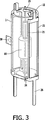
フレーム部材の実施例の詳細は、図2Aに示されており、それぞれの部分は、上述のサブアセンブリの記載におけるものと同じ符号によって示されている。図2Bにおいては、前記のような上端及び下端外側支持手段は、前記スリーブの外壁に沿って延在している2つの外側支持手段21内に結合されている。図2Bのフレーム部材を備えるサブアセンブリが、図3に示されている。このサブアセンブリは、更に、バーナ10及びゲッタ38を有する。
Details of an embodiment of the frame member are shown in FIG. 2A, where each part is indicated by the same reference as in the subassembly description above. In FIG. 2B, the upper and lower outer support means as described above are coupled into two outer support means 21 extending along the outer wall of the sleeve. A subassembly comprising the frame member of FIG. 2B is shown in FIG. The subassembly further includes a
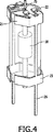
図4は、バーナ10を備えている他の代替的なサブアセンブリを示している。図1に示した実施例との主な違いは、外側支持手段21及び23の形状である。
FIG. 4 shows another alternative subassembly comprising a
図5は、本発明によるサブアセンブリを有するPARランプの模式図を示している。放電管10は、ここから延在している一対の対向する軸方向のリード線12、13を備えている円筒状のアルミニウム酸化物のエンベロープと、金属ハロゲン化合物の充填剤における放電を保持するための電極(図示略)とを有している。上端18及び下端20を有するアーク管10は、上方フィンガ25と下方フィンガ35との間に取り付けられており、上方フィンガ25と下方フィンガ35の両方は、それぞれのフレーム部材2,3の一部であり、石英スリーブ1によって支持されている。前記フレーム部材は、ステンレス鋼のワイヤによって形成されているのが好ましいが、Mo、Nb又はNiも使用されることができる。前記サブアセンブリは、更に、ゲッタ38を有する。
FIG. 5 shows a schematic view of a PAR lamp having a subassembly according to the invention. The
前記ランプの外側部分は、従来型の設計を有し、アルミニウム処理をされた内面(PAR)を備えているガラスエンベロープ45、前記のようなガラスに埋め込まれている一対のNi/Feフェルール48及び49、真鍮ベース50、中央接点52及びカバーレンズ54を含んでいる。フレーム部材2,3の支持部材26,36は、それぞれのフェルール48,49内に嵌合しており、フェルール48,49は、電気的にベース50及び中央接点52と接続されている。
The outer part of the lamp has a conventional design and has a glass envelope 45 with an aluminized inner surface (PAR), a pair of Ni / Fe ferrules 48 embedded in such glass and 49, a
前記ランプは、フレーム部材3にゲッタ38を溶接し、フレーム部材2,3を前記スリーブ上に締め付け、アーク管10を自身の軸方向のリード線12,13によってフィンガ25及び35の間に溶接することによって製造されることができる。フレーム部材2,3の支持部材26,36は、それぞれのフェルール48,49に蝋付け(braze)されている。次いで、カバー54がフレーム封止される又は代わりに接着され、振動耐性のある堅牢なランプが得られる。
The lamp welds a getter 38 to a frame member 3, clamps the
上述の実施例は、例として記載されたものであり、添付請求項の範囲を限定するものではないことに留意されたい。 It should be noted that the above-described embodiments have been described by way of example and do not limit the scope of the appended claims.
Claims (5)
Applications Claiming Priority (2)
| Application Number | Priority Date | Filing Date | Title |
|---|---|---|---|
| EP04104684 | 2004-09-27 | ||
| PCT/IB2005/052726 WO2006035324A2 (en) | 2004-09-27 | 2005-08-18 | Lamp with protective sleeve |
Publications (2)
| Publication Number | Publication Date |
|---|---|
| JP2008515142A JP2008515142A (en) | 2008-05-08 |
| JP4589397B2 true JP4589397B2 (en) | 2010-12-01 |
Family
ID=35457461
Family Applications (1)
| Application Number | Title | Priority Date | Filing Date |
|---|---|---|---|
| JP2007533006A Expired - Fee Related JP4589397B2 (en) | 2004-09-27 | 2005-08-18 | lamp |
Country Status (5)
| Country | Link |
|---|---|
| US (1) | US7851982B2 (en) |
| EP (1) | EP1812953A2 (en) |
| JP (1) | JP4589397B2 (en) |
| CN (1) | CN101027748B (en) |
| WO (1) | WO2006035324A2 (en) |
Families Citing this family (1)
| Publication number | Priority date | Publication date | Assignee | Title |
|---|---|---|---|---|
| US7375456B2 (en) * | 2005-03-31 | 2008-05-20 | Osram Sylvania Inc. | Mount for high intensity discharge lamp |
Family Cites Families (9)
| Publication number | Priority date | Publication date | Assignee | Title |
|---|---|---|---|---|
| GB260756A (en) * | 1925-10-20 | 1926-11-11 | Charles Edward Gisborne Newton | A combined lamp and heating or cooking stove |
| GB737913A (en) * | 1951-06-01 | 1955-10-05 | Gen Electric Co Ltd | Improvements in or relating to high pressure mercury vapour electric discharge lamps |
| US5136204A (en) * | 1989-12-11 | 1992-08-04 | Gte Products Corporation | Metal halide arc discharge lamp assembly |
| US5670840A (en) | 1992-11-12 | 1997-09-23 | Lanese; Gustino J. | Tungsten-halogen incandescent lamp with reduced risk of containment failure |
| US6157131A (en) * | 1998-08-18 | 2000-12-05 | Philips Electronics North America Corp. | Metal halide lamp with frame members |
| US6153968A (en) * | 1998-10-02 | 2000-11-28 | Philips Electronics North America Corp. | Metal halide lamp with stem mounted support frame for arc tube shield |
| US6329742B1 (en) * | 1999-06-02 | 2001-12-11 | Philips Electronics North America Corp. | Metal halide lamp with metal frame supporting a protective sleeve |
| US6741034B2 (en) * | 2002-08-22 | 2004-05-25 | Osram Sylvania Inc. | Starting aid for high intensity discharge lamp |
| EP1403905A3 (en) * | 2002-09-30 | 2006-06-14 | Osram Sylvania, Inc. | Snap-on spring clip for ceramic HID lamp |
-
2005
- 2005-08-18 CN CN2005800326895A patent/CN101027748B/en not_active Expired - Fee Related
- 2005-08-18 WO PCT/IB2005/052726 patent/WO2006035324A2/en not_active Ceased
- 2005-08-18 US US11/575,583 patent/US7851982B2/en not_active Expired - Fee Related
- 2005-08-18 JP JP2007533006A patent/JP4589397B2/en not_active Expired - Fee Related
- 2005-08-18 EP EP05781238A patent/EP1812953A2/en not_active Withdrawn
Also Published As
| Publication number | Publication date |
|---|---|
| JP2008515142A (en) | 2008-05-08 |
| EP1812953A2 (en) | 2007-08-01 |
| US7851982B2 (en) | 2010-12-14 |
| WO2006035324A3 (en) | 2006-07-13 |
| CN101027748B (en) | 2011-08-10 |
| US20080079345A1 (en) | 2008-04-03 |
| WO2006035324A2 (en) | 2006-04-06 |
| CN101027748A (en) | 2007-08-29 |
Similar Documents
| Publication | Publication Date | Title |
|---|---|---|
| EP1033742A2 (en) | Arc tube, mounting member and electric lamp assembly | |
| JP3471093B2 (en) | High pressure discharge lamp | |
| EP1070337B1 (en) | Support frame for a discharge vessel in a double-wall hid lamp | |
| JP2007115414A (en) | Sealing structure of discharge lamp | |
| US6157131A (en) | Metal halide lamp with frame members | |
| JP4589397B2 (en) | lamp | |
| US4658177A (en) | Electric lamp with oriented current conductors extending through a press seal | |
| US5859492A (en) | Electrode rod support for short arc lamp | |
| EP1101242B1 (en) | Metal halide lamp with protective sleeve | |
| JPH0817393A (en) | Discharge lamp | |
| JP5026973B2 (en) | lamp | |
| JP5884404B2 (en) | Discharge lamp assembly method and discharge lamp | |
| JP2005158568A (en) | Tube light bulb with base | |
| CN101506576B (en) | Large PAR lamp exhibiting excellent color with improved efficacy and life | |
| JP5248748B2 (en) | Shroud holder for quartz and ceramic arc tubes | |
| JP2006019303A (en) | Metal halide lamp | |
| JP5799437B2 (en) | High intensity discharge lamp with outer bulb protection structure | |
| JP5082012B2 (en) | Metal vapor discharge lamp and lighting device | |
| JPH10284001A (en) | High pressure discharge lamp | |
| JPH057728Y2 (en) | ||
| JP2008505438A (en) | How to install a lamp vessel in the lamp and outer bulb | |
| JPH05283049A (en) | Discharge lamp | |
| JPH1125847A (en) | Multi-tube discharge lamp, discharge lamp lighting device, and photochemical reaction device | |
| JP2006019045A (en) | Fluorescent lamp and lighting device | |
| JP2007134330A (en) | Metal halide arc discharge lamp |
Legal Events
| Date | Code | Title | Description |
|---|---|---|---|
| A621 | Written request for application examination |
Free format text: JAPANESE INTERMEDIATE CODE: A621 Effective date: 20080815 |
|
| A131 | Notification of reasons for refusal |
Free format text: JAPANESE INTERMEDIATE CODE: A131 Effective date: 20090917 |
|
| A521 | Request for written amendment filed |
Free format text: JAPANESE INTERMEDIATE CODE: A523 Effective date: 20091217 |
|
| A131 | Notification of reasons for refusal |
Free format text: JAPANESE INTERMEDIATE CODE: A131 Effective date: 20100209 |
|
| A521 | Request for written amendment filed |
Free format text: JAPANESE INTERMEDIATE CODE: A523 Effective date: 20100416 |
|
| TRDD | Decision of grant or rejection written | ||
| A01 | Written decision to grant a patent or to grant a registration (utility model) |
Free format text: JAPANESE INTERMEDIATE CODE: A01 Effective date: 20100812 |
|
| A01 | Written decision to grant a patent or to grant a registration (utility model) |
Free format text: JAPANESE INTERMEDIATE CODE: A01 |
|
| A61 | First payment of annual fees (during grant procedure) |
Free format text: JAPANESE INTERMEDIATE CODE: A61 Effective date: 20100909 |
|
| R150 | Certificate of patent or registration of utility model |
Free format text: JAPANESE INTERMEDIATE CODE: R150 |
|
| FPAY | Renewal fee payment (event date is renewal date of database) |
Free format text: PAYMENT UNTIL: 20130917 Year of fee payment: 3 |
|
| LAPS | Cancellation because of no payment of annual fees |