JP5082012B2 - Metal vapor discharge lamp and lighting device - Google Patents

Metal vapor discharge lamp and lighting device Download PDF

Info

Publication number
JP5082012B2
JP5082012B2 JP2011529095A JP2011529095A JP5082012B2 JP 5082012 B2 JP5082012 B2 JP 5082012B2 JP 2011529095 A JP2011529095 A JP 2011529095A JP 2011529095 A JP2011529095 A JP 2011529095A JP 5082012 B2 JP5082012 B2 JP 5082012B2
Authority
JP
Japan
Prior art keywords
tube
outer tube
base
lamp
metal vapor
Prior art date
Legal status (The legal status is an assumption and is not a legal conclusion. Google has not performed a legal analysis and makes no representation as to the accuracy of the status listed.)
Expired - Fee Related
Application number
JP2011529095A
Other languages
Japanese (ja)
Other versions
JPWO2012017581A1 (en
Inventor
有岐也 金澤
篤志 打保
俊介 柿坂
Current Assignee (The listed assignees may be inaccurate. Google has not performed a legal analysis and makes no representation or warranty as to the accuracy of the list.)
Panasonic Corp
Panasonic Holdings Corp
Original Assignee
Panasonic Corp
Matsushita Electric Industrial Co Ltd
Priority date (The priority date is an assumption and is not a legal conclusion. Google has not performed a legal analysis and makes no representation as to the accuracy of the date listed.)
Filing date
Publication date
Application filed by Panasonic Corp, Matsushita Electric Industrial Co Ltd filed Critical Panasonic Corp
Priority to JP2011529095A priority Critical patent/JP5082012B2/en
Application granted granted Critical
Publication of JP5082012B2 publication Critical patent/JP5082012B2/en
Publication of JPWO2012017581A1 publication Critical patent/JPWO2012017581A1/en
Expired - Fee Related legal-status Critical Current
Anticipated expiration legal-status Critical

Links

Images

Classifications

    • HELECTRICITY
    • H01ELECTRIC ELEMENTS
    • H01JELECTRIC DISCHARGE TUBES OR DISCHARGE LAMPS
    • H01J61/00Gas-discharge or vapour-discharge lamps
    • H01J61/02Details
    • H01J61/30Vessels; Containers
    • H01J61/34Double-wall vessels or containers
    • FMECHANICAL ENGINEERING; LIGHTING; HEATING; WEAPONS; BLASTING
    • F21LIGHTING
    • F21VFUNCTIONAL FEATURES OR DETAILS OF LIGHTING DEVICES OR SYSTEMS THEREOF; STRUCTURAL COMBINATIONS OF LIGHTING DEVICES WITH OTHER ARTICLES, NOT OTHERWISE PROVIDED FOR
    • F21V7/00Reflectors for light sources
    • HELECTRICITY
    • H01ELECTRIC ELEMENTS
    • H01JELECTRIC DISCHARGE TUBES OR DISCHARGE LAMPS
    • H01J5/00Details relating to vessels or to leading-in conductors common to two or more basic types of discharge tubes or lamps
    • H01J5/50Means forming part of the tube or lamps for the purpose of providing electrical connection to it
    • H01J5/54Means forming part of the tube or lamps for the purpose of providing electrical connection to it supported by a separate part, e.g. base
    • H01J5/56Shape of the separate part
    • HELECTRICITY
    • H01ELECTRIC ELEMENTS
    • H01JELECTRIC DISCHARGE TUBES OR DISCHARGE LAMPS
    • H01J5/00Details relating to vessels or to leading-in conductors common to two or more basic types of discharge tubes or lamps
    • H01J5/50Means forming part of the tube or lamps for the purpose of providing electrical connection to it
    • H01J5/54Means forming part of the tube or lamps for the purpose of providing electrical connection to it supported by a separate part, e.g. base
    • H01J5/58Means for fastening the separate part to the vessel, e.g. by cement
    • HELECTRICITY
    • H01ELECTRIC ELEMENTS
    • H01JELECTRIC DISCHARGE TUBES OR DISCHARGE LAMPS
    • H01J61/00Gas-discharge or vapour-discharge lamps
    • H01J61/82Lamps with high-pressure unconstricted discharge having a cold pressure > 400 Torr
    • H01J61/827Metal halide arc lamps
    • HELECTRICITY
    • H01ELECTRIC ELEMENTS
    • H01JELECTRIC DISCHARGE TUBES OR DISCHARGE LAMPS
    • H01J61/00Gas-discharge or vapour-discharge lamps
    • H01J61/84Lamps with discharge constricted by high pressure
    • H01J61/88Lamps with discharge constricted by high pressure with discharge additionally constricted by envelope

Description

本発明は、金属蒸気放電ランプおよび照明装置に関し、特に、メタルハライドランプにおける外管破損防止構造に関する。   The present invention relates to a metal vapor discharge lamp and a lighting device, and more particularly to a structure for preventing damage to an outer tube in a metal halide lamp.

従来のメタルハライドランプは、例えば図24に示すように、放電管501が収納された内管502がさらに外管503で被覆された三重管構造を有する。このような構造とすれば、放電管501の破裂により内管502が破損するようなことがあっても、それら破裂や破損によって生じた破片を外管503内に留めておくことができるため、放電管501破裂時に破片の飛散を防止することができる。   For example, as shown in FIG. 24, a conventional metal halide lamp has a triple tube structure in which an inner tube 502 in which a discharge tube 501 is housed is further covered with an outer tube 503. With such a structure, even if the inner tube 502 is damaged due to the rupture of the discharge tube 501, it is possible to keep the fragments generated by the rupture or damage in the outer tube 503. When the discharge tube 501 is ruptured, the fragments can be prevented from being scattered.

ところで、放電管501が破裂したときに、内管502の放電管近傍部分504が割れると、内管502の先端部505が外管503の閉塞部506に向かって吹き飛ぶことがある。このように先端部505が吹き飛んで閉塞部506に衝突すると、外管503が破損し破片が飛散するおそれがある。   By the way, when the discharge tube 501 is ruptured and the discharge tube vicinity portion 504 of the inner tube 502 is cracked, the distal end portion 505 of the inner tube 502 may be blown toward the closed portion 506 of the outer tube 503. Thus, when the front-end | tip part 505 blows off and collides with the obstruction | occlusion part 506, there exists a possibility that the outer tube | pipe 503 may be damaged and a fragment may be scattered.

そこで、このような外管503の破損を防止するために、内管502の先端部505の外側であって外管503の閉塞部506の内側に、外管破損防止用の破損防止部材507を配置することが提案されている(特許文献1)。破損防止部材507を設けることによって、外管503の閉塞部506に内管502の先端部505が直接衝突しなくなるため、外管503の破損を防止することができる。   Therefore, in order to prevent such damage to the outer tube 503, a breakage prevention member 507 for preventing breakage of the outer tube is provided outside the distal end portion 505 of the inner tube 502 and inside the closed portion 506 of the outer tube 503. Arrangement has been proposed (Patent Document 1). By providing the breakage preventing member 507, the distal end portion 505 of the inner tube 502 does not directly collide with the blocking portion 506 of the outer tube 503, and therefore the breakage of the outer tube 503 can be prevented.

特許第4436428号公報Japanese Patent No. 4436428

しかしながら、メタルハライドランプ500に破損防止部材507を設けると、部材点数の増加や組立作業の煩雑化により、メタルハライドランプ500の製造コストが高くなる。   However, when the breakage preventing member 507 is provided in the metal halide lamp 500, the manufacturing cost of the metal halide lamp 500 increases due to the increase in the number of members and the complexity of the assembly work.

本発明は、上記の課題に鑑み、破損防止部材を設けなくても外管が破損し難い金属蒸気放電ランプおよび照明装置を提供することを目的とする。   In view of the above problems, an object of the present invention is to provide a metal vapor discharge lamp and a lighting device in which an outer tube is not easily damaged without providing a breakage prevention member.

上記目的を達成するために、一端に開口部を有し他端に閉塞部を有する外管と、当該外管内に収納され内部に放電管が配置された内管と、前記外管の開口部に取り付けられた口金とを備え、前記外管の閉塞部の最薄肉厚をt[mm]とし、前記外管の閉塞部の内面と、前記内管の前記口金とは反対側の端部の外面との前記外管管軸方向における最短距離をd[mm]とした場合に、t≧1.1×d−0.4、且つ、0<d、且つ、0.3≦t、の関係を満たすことを特徴とする。To achieve the above object, an outer tube having an opening at one end and a closing portion at the other end, an inner tube housed in the outer tube and having a discharge tube disposed therein, and an opening of the outer tube A thin wall thickness of the closed portion of the outer tube is t [mm], and an inner surface of the closed portion of the outer tube and an end portion of the inner tube on the side opposite to the mouthpiece are provided. The relationship of t ≧ 1.1 × d −0.4 , 0 <d, and 0.3 ≦ t, where d [mm] is the shortest distance from the outer surface in the outer tube axis direction. It is characterized by satisfying.

本発明に係る照明装置は、上記金属蒸気放電ランプと、当該金属蒸気放電ランプから発せられた光を所望の方向に反射させる反射鏡とを備えることを特徴とする。   An illumination device according to the present invention includes the metal vapor discharge lamp and a reflecting mirror that reflects light emitted from the metal vapor discharge lamp in a desired direction.

本発明に係る金属蒸気放電ランプおよび照明装置は、前記最薄肉厚tと最短距離dとが、t≧1.1×d−0.4、且つ、0<d、且つ、0.3≦t、の関係を満たすため、破損防止部材を設けなくても外管が破損し難い。In the metal vapor discharge lamp and the lighting device according to the present invention, the thinnest thickness t and the shortest distance d are t ≧ 1.1 × d −0.4 , 0 <d, and 0.3 ≦ t. In order to satisfy the relationship,, the outer tube is not easily damaged without providing a breakage prevention member.

本発明の一態様に係る照明装置を示す一部破断側面図The partially broken side view which shows the illuminating device which concerns on 1 aspect of this invention 本発明の一態様に係る金属蒸気放電ランプを示す一部破断側面図The partially broken side view which shows the metal vapor discharge lamp which concerns on 1 aspect of this invention 本発明の一態様に係る金属蒸気放電ランプの放電管を示す断面図Sectional drawing which shows the discharge tube of the metal vapor discharge lamp which concerns on 1 aspect of this invention 消費電力39[W]の金属蒸気放電ランプについての安全性の評価結果を示す図The figure which shows the safety | security evaluation result about the metal vapor discharge lamp of power consumption 39 [W] 消費電力73[W]の金属蒸気放電ランプについての安全性の評価結果を示す図The figure which shows the safety | security evaluation result about the metal vapor discharge lamp of power consumption 73 [W] 定格電力35[W]タイプの金属蒸気放電ランプについて外管破損が生じ難い条件を説明するための図The figure for demonstrating the conditions which an outer tube | pipe is hard to produce about the rated power 35 [W] type metal vapor discharge lamp. 定格電力70[W]タイプの金属蒸気放電ランプについて外管破損が生じ難い条件を説明するための図The figure for demonstrating the conditions which an outer tube | pipe damage does not produce easily about the rated power 70 [W] type metal vapor discharge lamp 内管の先端部および外管の閉塞部の形状が外管破損に及ぼす影響を説明するための図The figure for demonstrating the influence which the shape of the front-end | tip part of an inner pipe | tube and the obstruction | occlusion part of an outer pipe | tube has on an outer pipe | tube breakage 変形例1に係る金属蒸気放電ランプを説明するための図The figure for demonstrating the metal vapor discharge lamp which concerns on the modification 1. 変形例2に係る金属蒸気放電ランプを説明するための図The figure for demonstrating the metal vapor discharge lamp which concerns on the modification 2. 変形例2に係る鍔状部材を示す斜視図The perspective view which shows the bowl-shaped member which concerns on the modification 2. 変形例3に係る金属蒸気放電ランプを説明するための図The figure for demonstrating the metal vapor discharge lamp which concerns on the modification 3. 変形例4に係る金属蒸気放電ランプを説明するための図The figure for demonstrating the metal vapor discharge lamp which concerns on the modification 4. 変形例5に係る金属蒸気放電ランプを説明するための図The figure for demonstrating the metal vapor discharge lamp which concerns on the modification 5. 変形例6に係る金属蒸気放電ランプを説明するための図The figure for demonstrating the metal vapor discharge lamp which concerns on the modification 6. 変形例7に係る金属蒸気放電ランプを説明するための図The figure for demonstrating the metal vapor discharge lamp which concerns on the modification 7. 変形例8に係る口金を示す斜視図The perspective view which shows the nozzle | cap | die which concerns on the modification 8. 変形例8に係る内管と口金との接合部分を示す斜視図The perspective view which shows the junction part of the inner pipe and base which concern on the modification 8. 変形例8に係る内管と口金との接合部分を示す断面図Sectional drawing which shows the junction part of the inner pipe and base which concern on the modification 8. 変形例9に係る口金を示す斜視図The perspective view which shows the nozzle | cap | die which concerns on the modification 9. 変形例9に係る内管と口金との接合部分を示す断面図Sectional drawing which shows the junction part of the inner tube and nozzle | cap | die which concern on the modification 9. 変形例10に係る内管と口金との接合部分を示す断面図Sectional drawing which shows the junction part of the inner pipe and base which concern on the modification 10. 変形例11に係る内管と口金との接合部分を示す断面図Sectional drawing which shows the junction part of the inner tube and base which concern on the modification 11 従来のメタルハライドランプを示す一部破断側面図Partially broken side view showing a conventional metal halide lamp

以下、本実施の形態に係る金属蒸気放電ランプおよび照明装置について、図面を参照しながら説明する。なお、各図面における部材の縮尺は実際のものとは異なる。また、本発明において、数値範囲を示す符号「〜」は、その両端の数値を含む。   Hereinafter, a metal vapor discharge lamp and a lighting device according to the present embodiment will be described with reference to the drawings. In addition, the scale of the member in each drawing differs from an actual thing. In the present invention, the sign “˜” indicating a numerical range includes numerical values at both ends.

[照明装置]
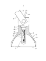
図1は、本発明の一態様に係る照明装置を示す一部破断側面図である。図1に示すように、本発明の一態様に係る照明装置1は、スポットライト照明装置であって、金属蒸気放電ランプ10(以下、単に「ランプ10」という。)と、当該ランプ10が内部に配置された照明器具20とを備える。なお、本発明に係る照明装置は、スポットライト照明装置に限定されず、他の用途の照明装置であっても良い。
[Lighting device]
FIG. 1 is a partially cutaway side view illustrating a lighting device according to one embodiment of the present invention. As shown in FIG. 1, an illuminating device 1 according to one embodiment of the present invention is a spotlight illuminating device, and includes a metal vapor discharge lamp 10 (hereinafter simply referred to as “lamp 10”) and the lamp 10 inside. And the lighting fixture 20 arranged in the. The lighting device according to the present invention is not limited to a spotlight lighting device, and may be a lighting device for other purposes.

ランプ10は、放電管100、内管200、外管300および口金400を備える。ランプ10の詳細については後述する。   The lamp 10 includes a discharge tube 100, an inner tube 200, an outer tube 300, and a base 400. Details of the lamp 10 will be described later.

照明器具20は、ランプ10から発せられた光を前方に反射させる凹状の反射面21を有する反射鏡22と、当該反射鏡22内に組み込まれたランプ装着用のソケット23と、壁や天井に反射鏡22を取着するための取着具24とを備える。   The luminaire 20 includes a reflecting mirror 22 having a concave reflecting surface 21 that reflects light emitted from the lamp 10 forward, a lamp mounting socket 23 incorporated in the reflecting mirror 22, and a wall or ceiling. And an attachment 24 for attaching the reflecting mirror 22.

反射鏡22は、前面に設けられた光取り出し用の開口部25が、ガラス板等のカバーによって塞がれておらず、開放状態である。そのため、放電管100の破裂により内管200および外管300が破損した場合は、それら破裂や破損によって生じた破片が照明器具20の外部へと飛散するおそれがある。ランプ10の動作中に破損して飛散した破片は高い温度を有しているため、人身事故にもつながる危険なものであるとともに火災に至るおそれもあることから、照明器具20には、外管300が破損し難いランプ10を取り付けることが強く望まれている。   In the reflecting mirror 22, the light extraction opening 25 provided on the front surface is not covered with a cover such as a glass plate and is in an open state. Therefore, when the inner tube 200 and the outer tube 300 are damaged due to the rupture of the discharge tube 100, there is a possibility that fragments generated due to the rupture or damage are scattered outside the lighting apparatus 20. Since the fragments that are broken and scattered during the operation of the lamp 10 have a high temperature, there is a danger of causing a personal injury and also a fire. It is strongly desired to attach the lamp 10 which is not easily damaged.

ソケット23は、供給線26を介して壁や天井に埋め込まれた点灯装置(不図示)と電気的に接続されており、ソケット23にランプ10の口金400を挿着すれば点灯装置からランプ10に電力が供給される。   The socket 23 is electrically connected to a lighting device (not shown) embedded in a wall or ceiling via a supply line 26, and if the base 400 of the lamp 10 is inserted into the socket 23, the lamp 10 is connected to the lamp 10. Is supplied with power.

取着具24は、壁や天井に回動自在に取り付けられたアーム27を有し、当該アーム27の先端には反射鏡22が回動自在に軸着されている。照明装置1から放射される光の向きは、アーム27または反射鏡22を回動させることにより調節可能である。   The attachment 24 has an arm 27 that is rotatably attached to a wall or ceiling, and a reflecting mirror 22 is pivotally attached to the tip of the arm 27. The direction of light emitted from the illumination device 1 can be adjusted by rotating the arm 27 or the reflecting mirror 22.

[金属蒸気放電ランプ]
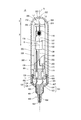
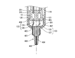
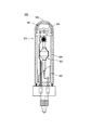
図2は、本発明の一態様に係る金属蒸気放電ランプを示す一部破断側面図である。図2に示すように、ランプ10は、3重管構造のメタルハライドランプであって、一端に開口部301を有し他端に閉塞部302を有する有底筒状の外管300と、当該外管300内に収納され内部に放電管100が配置された内管200と、外管300の開口部301に取り付けられた口金400とを備える。放電管100、内管200および外管300の管軸は、それぞれランプ10のランプ軸X(ランプ10の長手方向の中心軸)と略一致していることが好ましい。
[Metal vapor discharge lamp]
FIG. 2 is a partially broken side view showing a metal vapor discharge lamp according to one embodiment of the present invention. As shown in FIG. 2, the lamp 10 is a metal halide lamp having a triple tube structure, and includes a bottomed cylindrical outer tube 300 having an opening 301 at one end and a closing portion 302 at the other end, The inner tube 200 is housed in the tube 300 and the discharge tube 100 is disposed therein, and the base 400 is attached to the opening 301 of the outer tube 300. The tube axes of the discharge tube 100, the inner tube 200, and the outer tube 300 are preferably substantially coincident with the lamp axis X of the lamp 10 (the central axis in the longitudinal direction of the lamp 10).

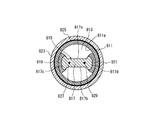
図3は、本発明の一態様に係る金属蒸気放電ランプの放電管を示す断面図である。図3に示すように、放電管100は、内部に気密封止された放電空間101を有する本管部102と、当該本管部102から放電管100の管軸(ランプ10の長手方向の中心軸であるランプ軸Xと一致している)方向両側に延出するように形成された細管部103,104と、本管部102と細管部103,104との隙間を埋めるように本管部102と細管部103,104との間に配置された円環状の接合部105,106とからなる外囲器107を有している。外囲器107は、例えばアルミナセラミックで形成されており、本管部102、細管部103,104、及び接合部103,104の3種類の部品を焼き嵌めて構成したものである。   FIG. 3 is a cross-sectional view illustrating a discharge tube of a metal vapor discharge lamp according to an aspect of the present invention. As shown in FIG. 3, the discharge tube 100 includes a main tube portion 102 having a discharge space 101 hermetically sealed therein, and a tube axis (the center in the longitudinal direction of the lamp 10) of the discharge tube 100 from the main tube portion 102. The main tube portion 103 and 104 formed so as to extend on both sides in the direction (which coincides with the lamp axis X, which is the shaft), and the main tube portion so as to fill a gap between the main tube portion 102 and the thin tube portions 103 and 104 An envelope 107 including annular joint portions 105 and 106 disposed between the tube 102 and the thin tube portions 103 and 104 is provided. The envelope 107 is made of alumina ceramic, for example, and is configured by shrink fitting three types of parts, the main pipe section 102, the narrow pipe sections 103 and 104, and the joint sections 103 and 104.

なお、外囲器107はアルミナセラミックで形成されたものに限定されず、その他の透光性セラミック(例えば、希土類アルミナガーネットセラミック等)、石英ガラス等で形成されていても良い。また、外囲器107は、3種類の部品を焼き嵌めて構成したものに限定されず、本管部と細管部との2種類の部品を焼き嵌めて構成したものでも良いし、本管部と細管部とを一体に成形したものであっても良い、さらには本管部において中央から端にかけての半分と細管部とを一体に成形した部品を接合させたものであっても良い。   The envelope 107 is not limited to the one formed of alumina ceramic, and may be formed of other translucent ceramic (for example, rare earth alumina garnet ceramic), quartz glass, or the like. Further, the envelope 107 is not limited to the one configured by shrink fitting three types of parts, and may be configured by shrink fitting two types of parts, the main pipe portion and the narrow pipe portion, or the main pipe portion. And the thin tube portion may be integrally formed, or a part obtained by integrally forming the half portion from the center to the end of the main tube portion and the thin tube portion may be joined.

放電空間101内には、発光物質である金属ハロゲン化物、始動補助ガスである希ガス、および、緩衝ガスである水銀がそれぞれ所定量封入されている。金属ハロゲン化物としては、例えば、ヨウ化ナトリウムやヨウ化ジスプロシウム、ヨウ化ホルミウム、ヨウ化ツリウム、ヨウ化タリウム、ヨウ化セリウム、ヨウ化プラセオジム、ヨウ化ネオジム、ヨウ化カルシウム、ヨウ化リチウム、ヨウ化インジウム、ヨウ化スカンジウム等が用いられる。なお、金属ハロゲン化物は、発光色により適宜決定される。   The discharge space 101 is filled with a predetermined amount of a metal halide that is a luminescent material, a rare gas that is a starting auxiliary gas, and mercury that is a buffer gas. Examples of the metal halide include sodium iodide, dysprosium iodide, holmium iodide, thulium iodide, thallium iodide, cerium iodide, praseodymium iodide, neodymium iodide, calcium iodide, lithium iodide, and iodide. Indium, scandium iodide, or the like is used. The metal halide is appropriately determined depending on the emission color.

放電管100は、先端部が本管部102の放電空間101内で互いに対向し、基端部が細管部103,104に挿入された一対の電極108,109を有する。そして、それら電極108,109の先端部間の中間位置が、放電管100の光中心Oとなる。   The discharge tube 100 has a pair of electrodes 108 and 109 whose distal ends are opposed to each other in the discharge space 101 of the main tube portion 102 and whose proximal ends are inserted into the narrow tube portions 103 and 104. The intermediate position between the tips of the electrodes 108 and 109 is the optical center O of the discharge tube 100.

電極108,109は、給電体114,115と、電極棒110,111と、当該電極棒110,111の先端部(放電空間101内で互いに対向する側の端部)に設けられた電極コイル112,113とを有する。給電体114,115は、例えば外囲器107をアルミナセラミックで構成した場合は、サーメットで構成するなど、外囲器107を構成する材料と熱膨張係数が近い材料で構成する。電極棒110,111は、耐ハロゲン性が強くかつ融点の高い金属、例えばタングステンで構成する。給電体114と電極棒110、給電体115と電極棒111は、たとえば溶接により接合されるか、もしくは給電体と電極棒とで融点の低いほうを融点の高いほうに溶着させることにより接合している。電極棒110,111において給電体のある側には、耐ハロゲン性が強い金属線、たとえばモリブデン線がコイル状に巻かれていてもよい。   The electrodes 108 and 109 are power feeders 114 and 115, electrode rods 110 and 111, and electrode coils 112 provided at tip portions of the electrode rods 110 and 111 (end portions on the side facing each other in the discharge space 101). , 113. For example, when the envelope 107 is made of alumina ceramic, the power feeders 114 and 115 are made of a material having a thermal expansion coefficient close to that of the material constituting the envelope 107, such as cermet. The electrode rods 110 and 111 are made of a metal having a high halogen resistance and a high melting point, such as tungsten. The power feeder 114 and the electrode rod 110, and the power feeder 115 and the electrode rod 111 are joined by welding, for example, or joined by welding the lower melting point to the higher melting point between the power feeder and the electrode rod. Yes. A metal wire having high halogen resistance, such as a molybdenum wire, may be wound in a coil shape on the electrode rods 110 and 111 on the side where the power feeder is provided.

電極108,109は、ランプ軸X上または、ランプ軸Xと平行な軸上に配置されていることが好ましい。理想的(設計的)には、電極108,109がランプ軸X上に配置されていること、つまり、電極108,109の電極棒110,111がランプ軸X上に配置されていることが好ましい。実際には、そのプロセスの精度上、電極108,109がランプ軸X上に配置されていない場合もある。   The electrodes 108 and 109 are preferably disposed on the lamp axis X or on an axis parallel to the lamp axis X. Ideally (designed), it is preferable that the electrodes 108 and 109 are arranged on the lamp axis X, that is, the electrode rods 110 and 111 of the electrodes 108 and 109 are arranged on the lamp axis X. . Actually, the electrodes 108 and 109 may not be arranged on the lamp axis X due to the accuracy of the process.

電極棒110,111の基端部は、細管部103,104内において給電体114,115の一端部と接合されており、給電体114,115は、細管部103,104内に流し込まれたフリットからなるシール材116,117によって封着されている。   The base end portions of the electrode rods 110 and 111 are joined to one end portions of the power feeding bodies 114 and 115 in the thin tube portions 103 and 104, and the power feeding bodies 114 and 115 are poured into the thin tube portions 103 and 104. It is sealed with sealing materials 116 and 117 made of.

図2に戻って、給電体114,115は、電力供給線118,119、金属箔120,121および導入線122,123を介して、口金400のシェル部401およびアイレット部402とそれぞれ電気的に接続されている。導入線122,123は、例えば、モリブデン製の第1リード線124,125と、ニッケル製の第2リード線126,127との継線であり、第1リード線124,125が金属箔120,121と接続され、第2リード線126,127が口金400と接続されている。第2リード線126,127を軟らかいニッケル製の金属線とすれば、第2リード線126,127と口金400との接続の作業性が向上する。   Returning to FIG. 2, the power feeders 114 and 115 are electrically connected to the shell portion 401 and the eyelet portion 402 of the base 400 through the power supply lines 118 and 119, the metal foils 120 and 121 and the lead-in wires 122 and 123, respectively. It is connected. The lead wires 122 and 123 are, for example, a connection between the first lead wires 124 and 125 made of molybdenum and the second lead wires 126 and 127 made of nickel, and the first lead wires 124 and 125 are the metal foil 120, The second lead wires 126 and 127 are connected to the base 400. If the second lead wires 126 and 127 are soft nickel metal wires, the workability of the connection between the second lead wires 126 and 127 and the base 400 is improved.

なお、一方の電力供給線118は、他方の電力供給線119および当該電力供給線119に接続された給電体115と対向する部分が、例えば石英ガラスなどからなるスリーブ128で被覆されている。このような構成とすれば、ランプ寿命末期に放電管100でリークが生じたとしても、反対極性となる部材間で生じる放電によって想定外の大きな電流が流れる続けることによって起こる点灯装置の損傷等の不具合を大幅に抑制することができる。   Note that one power supply line 118 is covered with a sleeve 128 made of, for example, quartz glass at a portion facing the other power supply line 119 and the power supply body 115 connected to the power supply line 119. With such a configuration, even if a leak occurs in the discharge tube 100 at the end of the lamp life, damage to the lighting device or the like caused by an unexpectedly large current continuously flowing due to discharge generated between members having opposite polarities. Problems can be greatly suppressed.

放電管100の寸法についての一例を説明する。図3に示すように、放電管100の本管部102の最大内径Aは、定格電力35[W]タイプの場合は4.0[mm]〜8.0[mm]、定格電力70[W]タイプの場合は6.0[mm]〜10.0[mm]である。本管部102の肉厚Bは、定格電力35[W]タイプの場合は0.3[mm]〜0.8[mm]、定格電力70[W]タイプの場合は0.4[mm]〜0.9[mm]である。電極間距離Cは、定格電力35[W]タイプの場合は3.0[mm]〜7.0[mm]、定格電力70[W]タイプの場合は5.0[mm]〜9.0[mm]である。図2に示すように、放電管100の光中心Oから内管200の先端部202までの距離Dは、定格電力35[W]タイプの場合は20.0[mm]〜40.0[mm]、定格電力70[W]タイプの場合も20.0[mm]〜40.0[mm]である。なお、上記の寸法は図3に示すように3種類の部品を焼き嵌めて構成したものに限定されず、本管部と細管部との2種類の部品を焼き嵌めて構成したものでもよいし、本管部と細管部とを一体に成形したものであっても良い、さらには本管部における中央から端にいたる半分と細管部とを一体に成形した部品を接合させたものであっても同様である。   An example of the dimensions of the discharge tube 100 will be described. As shown in FIG. 3, the maximum inner diameter A of the main tube portion 102 of the discharge tube 100 is 4.0 [mm] to 8.0 [mm] in the case of the rated power 35 [W] type, and the rated power 70 [W]. ] Type is 6.0 [mm] to 10.0 [mm]. The wall thickness B of the main pipe portion 102 is 0.3 [mm] to 0.8 [mm] for the rated power 35 [W] type, and 0.4 [mm] for the rated power 70 [W] type. It is -0.9 [mm]. The distance C between the electrodes is 3.0 [mm] to 7.0 [mm] for the rated power 35 [W] type, and 5.0 [mm] to 9.0 for the rated power 70 [W] type. [Mm]. As shown in FIG. 2, the distance D from the optical center O of the discharge tube 100 to the tip portion 202 of the inner tube 200 is 20.0 [mm] to 40.0 [mm] in the case of a rated power of 35 [W] type. In the case of the rated power of 70 [W] type, it is also 20.0 [mm] to 40.0 [mm]. Note that the above dimensions are not limited to those constructed by shrink fitting three types of parts as shown in FIG. 3, but may be constructed by shrink fitting two types of parts, a main pipe part and a narrow pipe part. In addition, the main pipe part and the thin pipe part may be formed integrally, and further, the half part from the center to the end of the main pipe part and the part formed by integrally forming the thin pipe part are joined. Is the same.

内管200は、例えば、片封止型の気密容器であって、口金400側の端部がピンチシール法によって圧潰封止された封止部201となっており、口金400とは反対側(ランプ頂部側)の端部が外管300の閉塞部302と対向する先端部202となっている。なお、封止部201には、金属箔120,121が封止されている。   The inner tube 200 is, for example, a single-sealing type airtight container, and the end portion on the side of the base 400 is a sealing portion 201 that is crushed and sealed by the pinch seal method, and is opposite to the base 400 ( An end on the lamp top side is a tip 202 that faces the closing portion 302 of the outer tube 300. Note that metal foils 120 and 121 are sealed in the sealing portion 201.

口金400は、エジソンタイプであって、シェル部401およびアイレット部402を有する。一方の第2リード線126は、口金400に設けられた貫通孔403を貫通して外部へと導出され、シェル部401に接合されることで口金400に固定されている。他方の第2リード線127は、口金400に設けられた貫通孔404を貫通してアイレット部402と接合されることで、口金400に固定されている。   The base 400 is an Edison type and has a shell portion 401 and an eyelet portion 402. One second lead 126 passes through a through-hole 403 provided in the base 400, is led out to the outside, and is fixed to the base 400 by being joined to the shell portion 401. The other second lead wire 127 is fixed to the base 400 by passing through a through hole 404 provided in the base 400 and joining to the eyelet part 402.

口金400の外管側端部405は、外管300の開口部301内に挿入されている。この構成であれば口金400部分においてランプ10の外径が口金400よりも大きくなることがないため、照明器具20の反射鏡22のネック部の開口径を必要以上に大きくしないで済み、照明器具20の反射効率を高めることができる。   The outer tube side end 405 of the base 400 is inserted into the opening 301 of the outer tube 300. With this configuration, since the outer diameter of the lamp 10 does not become larger than the base 400 in the base 400 portion, the opening diameter of the neck portion of the reflecting mirror 22 of the lighting fixture 20 need not be increased more than necessary. The reflection efficiency of 20 can be increased.

口金400の外周面406には周方向に沿った円環状のフランジ部407が形成されている。フランジ部407は、外周面406から外管300の開口部301の厚み分だけランプ軸Xと直交する方向に膨出しており、当該フランジ部407に外管300の開口部301を当接させることによって、ランプ軸X方向における口金400と外管300との位置決めを容易に行なうことができる。   An annular flange portion 407 is formed on the outer peripheral surface 406 of the base 400 along the circumferential direction. The flange portion 407 bulges from the outer peripheral surface 406 in the direction orthogonal to the lamp axis X by the thickness of the opening portion 301 of the outer tube 300, and the opening portion 301 of the outer tube 300 is brought into contact with the flange portion 407. Thus, the base 400 and the outer tube 300 can be easily positioned in the lamp axis X direction.

外管300の開口部301は、少なくとも口金400の外周面405またはフランジ部407のいずれかに固着される。この固着手段としては、外管300の開口部301と口金400の外周面405との間や外管300の開口部301と口金400のフランジ部407との間に、セメント等の接着剤(例えば朝日化学工業株式会社製のスミセラム(登録商標)、日産化学工業株式会社製のボンドエックス(登録商標)等の無機系接着剤)を配置してもよいし、外管300の開口部301に凸部(もしくは凹部)を設けかつ開口部301に当接する口金400の側面に凹部(凸部)を設けて両者を嵌合させた係止構造であっても良いし、さらに両者を組み合わせたものであっても良い。さらには後述の変形例7に述べるように、外管300の開口部301とフランジ部407とを機械的に固着させる手段を口金400の一部に設けてもよい。   The opening 301 of the outer tube 300 is fixed to at least either the outer peripheral surface 405 or the flange portion 407 of the base 400. As this adhering means, an adhesive such as cement (for example, between the opening 301 of the outer tube 300 and the outer peripheral surface 405 of the base 400 or between the opening 301 of the outer tube 300 and the flange portion 407 of the base 400). Inorganic adhesives such as SUMICERAM (registered trademark) manufactured by Asahi Chemical Industry Co., Ltd. or Bond X (registered trademark) manufactured by NISSAN CHEMICAL INDUSTRY CO., LTD. A locking structure in which a concave portion (convex portion) is provided on the side surface of the base 400 that is provided with a portion (or a concave portion) and is in contact with the opening 301 and the both are fitted may be used. There may be. Further, as will be described in Modification 7 described later, a means for mechanically fixing the opening 301 and the flange 407 of the outer tube 300 may be provided in a part of the base 400.

内管200の封止部201は、セメント等の接着剤11によって口金400に固着されており、これにより内管200は口金400に支持されている。また、内管200の封止部201は、接着剤11によって外管300にも固着されており、これにより内管200は外管300にも支持されている。   The sealing portion 201 of the inner pipe 200 is fixed to the base 400 with an adhesive 11 such as cement, and thereby the inner pipe 200 is supported by the base 400. Further, the sealing portion 201 of the inner tube 200 is also fixed to the outer tube 300 by the adhesive 11, whereby the inner tube 200 is also supported by the outer tube 300.

図2に戻って、先端部202には、内管200内を真空引きする際に用いた排気管の残部であるチップオフ部分203が存在している。内管200内を真空引きすることによって、給電体114,115や電力供給線118,119などの金属部材が高温にさらされ酸化するのを防止することができる。なお、内管200内を真空にする代わりに、前記内管200内に不活性ガスを充満させることによっても、金属部材が酸化するのを防止することができる。   Returning to FIG. 2, the tip portion 202 has a tip-off portion 203 which is the remaining portion of the exhaust pipe used when evacuating the inner pipe 200. By evacuating the inner tube 200, metal members such as the power feeders 114 and 115 and the power supply lines 118 and 119 can be prevented from being exposed to high temperatures and being oxidized. In addition, it is possible to prevent the metal member from being oxidized by filling the inner tube 200 with an inert gas instead of evacuating the inner tube 200.

不可避的に形状が急峻に変化せざるをえないチップオフ部分203を除く先端部202は、略半球状であることが好ましい。好ましい理由は後述する。さらに、先端部202が略半球状の場合において、内管200の中間部205の外径は13[mm]〜17[mm]、内管200の中間部205の肉厚は1[mm]〜2[mm]であり、外管300の破損し難いランプ10を得るために、先端部202の外面204においてチップオフ部分203を除いた曲面部分で急峻な形状変化をする部分、すなわち肩部206の外面の曲率半径r[mm]は、2.0≦r≦9.0であることが好ましく、3.0≦r≦9.0であることがより好ましく、5.0≦r≦9.0であることがさらに好ましい。つまり、先端部202の肩部206の外面の形状について曲率半径rが小である場合、すなわち内管200の先端部202の肩部206の丸みが小さく、先端部202の形状に急峻な変化を有すると、製造における歩留まりが悪化し、コスト高になるためである。一方、先端部202は、肩部206を含めて急峻な変化を有さない略半球状に近い形状である方が、内管200を構成する材料を形状変化させる加工に伴って生じる歪が少なく、そのぶん堅牢であるため好ましい。   It is preferable that the tip portion 202 except the tip-off portion 203 inevitably change in shape sharply, has a substantially hemispherical shape. The preferable reason will be described later. Further, when the tip 202 is substantially hemispherical, the outer diameter of the intermediate portion 205 of the inner tube 200 is 13 [mm] to 17 [mm], and the thickness of the intermediate portion 205 of the inner tube 200 is 1 [mm] to In order to obtain the lamp 10 that is 2 [mm] and is not easily damaged by the outer tube 300, a portion of the outer surface 204 of the tip portion 202 that undergoes a sharp change in the curved surface portion excluding the tip-off portion 203, that is, a shoulder portion 206. The outer surface has a curvature radius r [mm] of preferably 2.0 ≦ r ≦ 9.0, more preferably 3.0 ≦ r ≦ 9.0, and 5.0 ≦ r ≦ 9. More preferably, it is 0. That is, when the curvature radius r is small with respect to the shape of the outer surface of the shoulder portion 206 of the distal end portion 202, that is, the roundness of the shoulder portion 206 of the distal end portion 202 of the inner tube 200 is small, and the shape of the distal end portion 202 changes sharply. This is because the yield in manufacturing deteriorates and the cost increases. On the other hand, the tip 202 has a substantially hemispherical shape that does not have a steep change, including the shoulder 206, and the distortion that occurs due to the process of changing the shape of the material constituting the inner tube 200 is less. It is preferable because of its robustness.

内管200は、封止部201と先端部202との間の中間部205が例えば略円筒状であって、当該中間部205内に放電管100の外囲器107が配置されている。放電管100が破裂した場合は、内管200の中間部205が概ね破損する。なお、中間部205の形状は略円筒状に限定されず、多角形の筒状や楕円の筒状など円筒以外の筒状であっても良い。また、中間部205の内径及び外径は必ずしも内管200の中心軸方向に沿って均一である必要はなく、例えば放電管100の本管部107に相当する位置の内径および外径が、それ以外の位置の内径および外径よりも大きくなっているような形状、すなわち一部に膨出部を有するような形状であっても良い。   In the inner tube 200, an intermediate portion 205 between the sealing portion 201 and the distal end portion 202 is, for example, a substantially cylindrical shape, and the envelope 107 of the discharge tube 100 is disposed in the intermediate portion 205. When the discharge tube 100 is ruptured, the intermediate portion 205 of the inner tube 200 is generally damaged. The shape of the intermediate portion 205 is not limited to a substantially cylindrical shape, and may be a cylindrical shape other than a cylinder, such as a polygonal cylindrical shape or an elliptical cylindrical shape. Further, the inner diameter and the outer diameter of the intermediate portion 205 are not necessarily uniform along the central axis direction of the inner tube 200. For example, the inner diameter and the outer diameter at a position corresponding to the main tube portion 107 of the discharge tube 100 are the same. A shape that is larger than the inner diameter and the outer diameter at a position other than that, that is, a shape having a bulging portion in part.

内管200は、例えば石英ガラスで形成されている。なお、内管200は、石英ガラスで形成されたものに限定されず、アルミナセラミック等の透光性セラミック、硬質ガラス等で形成されていても良い。   The inner tube 200 is made of, for example, quartz glass. The inner tube 200 is not limited to the one formed of quartz glass, and may be formed of a translucent ceramic such as alumina ceramic, hard glass, or the like.

外管300は、例えば、口金側端部である開口部(ネック部)301と、口金400とは反対側の端部である閉塞部302と、それら開口部301および閉塞部302の間の中間部303とで構成される有底筒状であって、放電管100の破裂によって内管200が破損した場合に、それら破裂や破損で生じた破片が飛散するのを防止する役割を果たす。   The outer tube 300 includes, for example, an opening (neck portion) 301 that is a base side end, a closing portion 302 that is an end opposite to the base 400, and an intermediate between the opening 301 and the closing portion 302. It is a bottomed cylindrical shape constituted by the portion 303, and when the inner tube 200 is damaged due to the rupture of the discharge tube 100, it plays a role of preventing the fragments generated by the rupture or damage from being scattered.

外管300の開口部301には、接着剤11を介して、口金400が取り付けられている。なお、外管300の開口部301に口金400を取り付ける構成としては、接着剤11を用いるものに限定されず、例えば、開口部301および口金400にそれぞれ係合部(不図示)を設けて(例えば外管300の内面304に凸部を設け口金400の外周面406に凹部を設けて)、それら係合部を係合させることにより開口部301に口金400を直接取り付ける構成であっても良い。また、口金400に設けたホルダ(不図示)によって外管300と口金400とを接合する構成であっても良い。さらに、クリップ等の弾性のある金属部材(不図示)を口金400に設けて、その金属部材で外管300を保持する構成であっても良い。上記構成により、外管300の落下を防止することができる。なお、外管300は、口金400とは接合されておらず、内管200と接着剤11により接合された構成であっても良い。   A base 400 is attached to the opening 301 of the outer tube 300 via the adhesive 11. In addition, as a structure which attaches the nozzle | cap | die 400 to the opening part 301 of the outer tube | pipe 300, it is not limited to what uses the adhesive agent 11, For example, an engaging part (not shown) is each provided in the opening part 301 and the nozzle | cap | die 400 ( For example, a configuration may be adopted in which a convex portion is provided on the inner surface 304 of the outer tube 300 and a concave portion is provided on the outer peripheral surface 406 of the base 400, and the base 400 is directly attached to the opening 301 by engaging these engaging portions. . Moreover, the structure which joins the outer tube | pipe 300 and the nozzle | cap | die 400 with the holder (not shown) provided in the nozzle | cap | die 400 may be sufficient. Further, an elastic metal member (not shown) such as a clip may be provided on the base 400 and the outer tube 300 may be held by the metal member. With the above configuration, the outer tube 300 can be prevented from falling. The outer tube 300 may not be bonded to the base 400 but may be configured to be bonded to the inner tube 200 with the adhesive 11.

外管300の閉塞部302は、例えば、略半球状または略板状であることが好ましい。閉塞部302が略半球状の場合は、閉塞部302の内面304の曲率半径Rが8.0以上であることが好ましい。閉塞部302が略板状の場合は、閉塞部302の内面304が平面であることが好ましい。それぞれの好ましい理由は後述する。   For example, the closing portion 302 of the outer tube 300 is preferably substantially hemispherical or substantially plate-shaped. When the closing part 302 is substantially hemispherical, the curvature radius R of the inner surface 304 of the closing part 302 is preferably 8.0 or more. When the blocking part 302 is substantially plate-shaped, the inner surface 304 of the blocking part 302 is preferably a flat surface. The reason for each preference will be described later.

閉塞部302がどの部分であるのかを明確にするために、閉塞部302と中間部303との境界を明確にしておく。放電管から閉塞部側で中間部303と閉塞部302との境界付近において、軸方向に対して直交する方向に計測した内径が軸方向に対して略等しい部分は中間部303に属する。これに対し、ランプ軸Xに垂直な断面で外囲器107がなく、かつ内径が小さくなり始めるところが中間部303と閉塞部302との境界である。その境界よりもランプ頂部側が閉塞部302である。閉塞部302が略半球状の場合は、ランプ頂部側に向かって内径が漸次小さくなっている部分が閉塞部302である。閉塞部302が略板状の場合は、略板状の部分とその周縁のコーナー部分とが閉塞部302である。   In order to clarify which part the blocking part 302 is, the boundary between the blocking part 302 and the intermediate part 303 is made clear. In the vicinity of the boundary between the intermediate portion 303 and the closed portion 302 on the closed portion side from the discharge tube, the portion whose inner diameter measured in the direction orthogonal to the axial direction is substantially equal to the axial direction belongs to the intermediate portion 303. In contrast, the boundary between the intermediate portion 303 and the closed portion 302 is where the envelope 107 does not exist in the cross section perpendicular to the lamp axis X and the inner diameter starts to decrease. The blocking portion 302 is located on the lamp top side from the boundary. When the closing part 302 is substantially hemispherical, the part where the inner diameter gradually decreases toward the lamp top side is the closing part 302. When the closing part 302 is substantially plate-shaped, the substantially plate-like part and the corner part of the periphery thereof are the closing part 302.

中間部303は、ランプ10のコンパクト性および照明器具20への適合性を確保するために、最大外径が16[mm]〜27[mm]、ネック径(封止部201付近の径)が16[mm]〜23[mm]、肉厚が1[mm]〜2[mm]であることが好ましい。   The intermediate portion 303 has a maximum outer diameter of 16 [mm] to 27 [mm] and a neck diameter (a diameter in the vicinity of the sealing portion 201) in order to ensure compactness of the lamp 10 and suitability for the lighting fixture 20. It is preferable that the thickness is 16 [mm] to 23 [mm] and the thickness is 1 [mm] to 2 [mm].

特に、図2に示すように、中間部303および開口部(ネック部)301の外径が均一な外管300を備えるランプ10の場合は、中間部303の外径が16[mm]〜22[mm]であることが好ましい。これにより、細身形状で美観に優れ、且つ、コンパクトなランプ10とすることができる。その場合、中間部303の内径は13[mm]〜17[mm]が好ましく、中間部303の肉厚は1.0[mm]〜2.0[mm]が好ましい。   In particular, as shown in FIG. 2, in the case of the lamp 10 including the outer tube 300 in which the outer diameter of the intermediate portion 303 and the opening (neck portion) 301 is uniform, the outer diameter of the intermediate portion 303 is 16 mm to 22 mm. [Mm] is preferable. Thereby, it can be set as the compact lamp | ramp 10 which is excellent in aesthetics with a slim shape. In that case, the inner diameter of the intermediate portion 303 is preferably 13 [mm] to 17 [mm], and the thickness of the intermediate portion 303 is preferably 1.0 [mm] to 2.0 [mm].

中間部303は、ランプ10のコンパクト性を確保するためには、内管200の中間部205と同じ略円筒状であることが好ましい。また、外管300の中間部303の内面と内管200の中間部205の外面との隙間は、ランプ軸Xと直行する方向において略均一であることが好ましい。   In order to ensure the compactness of the lamp 10, the intermediate portion 303 is preferably substantially the same cylindrical shape as the intermediate portion 205 of the inner tube 200. In addition, the gap between the inner surface of the intermediate portion 303 of the outer tube 300 and the outer surface of the intermediate portion 205 of the inner tube 200 is preferably substantially uniform in the direction orthogonal to the lamp axis X.

なお、中間部303の形状は略円筒状に限定されず、多角形の筒状や楕円の筒状など円筒以外の筒状であっても良い。   The shape of the intermediate portion 303 is not limited to a substantially cylindrical shape, and may be a cylindrical shape other than a cylinder, such as a polygonal cylindrical shape or an elliptical cylindrical shape.

組立工程において外管300を内管200に被せる際のクリアランスを確保するためには、外管300の中間部303の内面と内管200の中間部205の外面との隙間は、中間部303のストレート部に対応する領域において平均で1[mm]〜3[mm]、中間部303の膨出部306に対応する領域において平均で1[mm]〜5[mm]であることが好ましい。   In order to secure a clearance when the outer tube 300 is put on the inner tube 200 in the assembly process, the gap between the inner surface of the intermediate portion 303 of the outer tube 300 and the outer surface of the intermediate portion 205 of the inner tube 200 is It is preferable that the average is 1 [mm] to 3 [mm] in the region corresponding to the straight portion, and the average is 1 [mm] to 5 [mm] in the region corresponding to the bulging portion 306 of the intermediate portion 303.

外管300は、例えば硬質ガラスで形成されている。なお、外管300は、硬質ガラスで形成されたものに限定されず、アルミナセラミック等の透光性セラミック、石英ガラス等で形成されていても良い。   The outer tube 300 is made of hard glass, for example. The outer tube 300 is not limited to the one made of hard glass, and may be made of a translucent ceramic such as alumina ceramic, quartz glass, or the like.

外管300の閉塞部302の最薄肉厚をt[mm]とし、外管300の閉塞部302の内面304と内管200の先端部202の外面204との外管管軸方向における最短距離をd[mm]とした場合に、t≧1.1×d−0.4、且つ、0<d、且つ、0.3≦t、の関係を満たす。The thinnest thickness of the closed portion 302 of the outer tube 300 is t [mm], and the shortest distance between the inner surface 304 of the closed portion 302 of the outer tube 300 and the outer surface 204 of the distal end portion 202 of the inner tube 200 in the outer tube axis direction. When d [mm] is satisfied, the relationship of t ≧ 1.1 × d −0.4 , 0 <d, and 0.3 ≦ t is satisfied.

放電管100破損時の外管300の閉塞部302への内管200が破損した破片の飛散について、破損した直後は破片の速度よりも封入ガスの拡散速度の方が大きいため封入ガスのほうが外管300に先に到達し、外管300の内面304に跳ね返ってきた封入ガスにより飛散破片が押し戻され、これにより破片の速度低下が生じる。したがって、最短距離dが小さい場合は外管300に到達するまでに飛散破片の速度低下が小さな状態で到達するので外管300への衝撃が強く、外管300割れに至り易い。その際、閉塞部302の肉厚が厚くなると耐衝撃性が強くなり閉塞部302割れは生じ難くなる。閉塞部302の肉厚とは、内面304と外面305との間の内面304に対する法線方向における幅を意味する。閉塞部302の肉厚の値は、X線を用いた測定により、または、外管300の断面をノギス等で測定することにより、得ることができる。   When the discharge tube 100 is broken, the spatter of the broken pieces of the inner tube 200 to the closed portion 302 of the outer tube 300 is immediately after the breakage, so the diffusion rate of the filled gas is larger than the speed of the broken pieces. The scattered fragments are pushed back by the sealed gas that has reached the tube 300 first and bounced back to the inner surface 304 of the outer tube 300, thereby reducing the speed of the fragments. Therefore, when the shortest distance d is small, the speed reduction of the scattered fragments reaches the outer tube 300 until reaching the outer tube 300, so that the impact on the outer tube 300 is strong and the outer tube 300 is easily cracked. At this time, if the thickness of the closed portion 302 is increased, the impact resistance is increased and cracking of the closed portion 302 is less likely to occur. The wall thickness of the blocking portion 302 means a width in the normal direction with respect to the inner surface 304 between the inner surface 304 and the outer surface 305. The thickness value of the blocking portion 302 can be obtained by measurement using X-rays or by measuring the cross section of the outer tube 300 with calipers or the like.

外管300の閉塞部302の肉厚の下限に関して、最薄肉厚tが薄いと、外管300の加工が困難であり所望の形状の外管300を得ることができないばかりか、運搬時の衝撃や照明器具への取り付けの際に外管が破損するおそれすらある。したがって、最薄肉厚tは0.3[mm]以上が好ましい。さらに、最薄肉厚tを1.0[mm]以下にすることは製造上非常に困難であるため、最薄肉厚tは1.1[mm]以上が好ましい。   Regarding the lower limit of the wall thickness of the closed portion 302 of the outer tube 300, if the thinnest wall thickness t is thin, it is difficult to process the outer tube 300 and the outer tube 300 having a desired shape cannot be obtained. There is a possibility that the outer tube may be damaged when it is attached to a lighting fixture. Therefore, the thinnest wall thickness t is preferably 0.3 [mm] or more. Furthermore, since it is very difficult to manufacture the thinnest wall thickness t of 1.0 [mm] or less, the thinnest wall thickness t is preferably 1.1 [mm] or more.

一方、外管300の閉塞部302の肉厚の上限に関して、中間部との一体性を考慮し、加工の容易性の観点から、最薄肉厚tは5.0[mm]以下が好ましい。さらに、最薄肉厚tが厚いと、外管300の閉塞部302を略半球状や略板状に加工するのが困難である。したがって、最薄肉厚tは、外管300の閉塞部302の加工性や、閉塞部302と中間部303との一体性を考慮して、3.0[mm]以下でが好ましい。   On the other hand, regarding the upper limit of the thickness of the closed portion 302 of the outer tube 300, the thinnest thickness t is preferably 5.0 [mm] or less from the viewpoint of ease of processing in consideration of the integrity with the intermediate portion. Further, when the thinnest thickness t is large, it is difficult to process the closed portion 302 of the outer tube 300 into a substantially hemispherical shape or a substantially plate shape. Therefore, the thinnest thickness t is preferably 3.0 [mm] or less in consideration of the workability of the closed portion 302 of the outer tube 300 and the unity between the closed portion 302 and the intermediate portion 303.

最短距離dは、15「mm」以下であることが好ましい。最短距離dが15[mm]を超えると、外管300に対し内管200の姿勢を適正に保つことが困難になる。すなわち、外管300の管軸と内管200の管軸とが平行になるよう、外管300に対し内管200を位置合わせするのが困難になる。   The shortest distance d is preferably 15 “mm” or less. When the shortest distance d exceeds 15 [mm], it is difficult to keep the posture of the inner tube 200 properly with respect to the outer tube 300. That is, it is difficult to align the inner tube 200 with respect to the outer tube 300 so that the tube axis of the outer tube 300 and the tube axis of the inner tube 200 are parallel to each other.

本実施の形態における最短距離dは、図2に示すように、内管200の先端部202のコーナー部分206から外管300の閉塞部302の内面304までのランプ軸X方向における距離であったが、最短距離dはこれに限定されない。例えば、内管200のチップオフ部203から外管300の閉塞部302までのランプ軸X方向における距離Eが、内管200の先端部202のコーナー部分206から外管300の閉塞部302の内面304までのランプ軸X方向における距離よりも短い場合は、距離Eが最短距離dとなり得る。   The shortest distance d in the present embodiment is a distance in the lamp axis X direction from the corner portion 206 of the tip portion 202 of the inner tube 200 to the inner surface 304 of the closed portion 302 of the outer tube 300, as shown in FIG. However, the shortest distance d is not limited to this. For example, the distance E in the lamp axis X direction from the tip-off portion 203 of the inner tube 200 to the closed portion 302 of the outer tube 300 is such that the corner portion 206 of the distal end portion 202 of the inner tube 200 is the inner surface of the closed portion 302 of the outer tube 300. When the distance is shorter than 304 in the lamp axis X direction, the distance E can be the shortest distance d.

最薄肉厚tと最短距離dとが上記関係を満たしていれば、特許文献1に記載の破損防止部材を設けなくても、外管300の破損を防止することができる。上記関係は、定格電力35[W]タイプ、および、定格電力70[W]タイプのランプを用いて行なった以下の安全性評価により明らかになった。   If the thinnest thickness t and the shortest distance d satisfy the above relationship, the outer tube 300 can be prevented from being damaged without providing the damage preventing member described in Patent Document 1. The above relationship has been clarified by the following safety evaluation conducted using rated power 35 [W] type lamps and rated power 70 [W] type lamps.

まず、定格電力35[W]タイプのランプとしてサンプル1〜15のランプを4本ずつ用意し、UL規格番号1572の試験(アメリカ保険業者安全試験所:Underwriters Laboratories Inc./UL規格番号1572/規格の表題 高電圧放電灯取付具/1991年度版)に基づいて、放電管破損時の安全性を評価した。具体的には、各ランプを15分間安定点灯させ、その後回路を短絡させることにより大電流を流して放電管を破裂させ、4本いずれのランプの外管にもヒビが入らなければ「良好」と評価し、1本でもランプの外管にヒビが入れば「不良」と評価した。   First, four lamps of samples 1 to 15 were prepared as rated power 35 [W] type lamps, and tested according to UL standard number 1572 (American Insurers Safety Laboratory: Underwriters Laboratories Inc./UL standard number 1572 / standard). The safety at the time of discharge tube breakage was evaluated based on the high voltage discharge lamp fixture / 1991 edition). Specifically, each lamp is lit stably for 15 minutes, and then the circuit is short-circuited to cause a large current to flow and the discharge tube is ruptured. If the outer tube of any of the four lamps does not crack, it is “good”. It was evaluated as “bad” if even one of the lamps cracked in the outer tube.

また、定格電力70[W]タイプのランプとしてサンプル16〜30のランプを4本ずつ用意し、定格電力35[W]タイプのランプの場合と同様の方法により放電管破損時の安全性を評価した。   Also, four lamps of samples 16 to 30 are prepared as rated power 70 [W] type lamps, and the safety at the time of discharge tube breakage is evaluated in the same manner as the rated power 35 [W] type lamps. did.

ここで、定格電力35[W]タイプのランプとは、消費電力が30[W]〜45[W]、アーク長(電極108,109間の距離)が2.5[mm]〜5.5[mm]、水銀量が3.0[mg]〜4.5[mg]である。評価には、定格電力35[W]タイプのランプの一例として、消費電力が39[W]、アーク長が4.5[mm]、水銀量が4.5[mg]、外管の中間部および開口部の最大外径が21[mm]、外管の中間部および開口部の肉厚が1.5[mm]のランプを用いた。   Here, the rated power 35 [W] type lamp has a power consumption of 30 [W] to 45 [W] and an arc length (distance between the electrodes 108 and 109) of 2.5 [mm] to 5.5. [Mm], mercury amount is 3.0 [mg] to 4.5 [mg]. For the evaluation, as an example of a rated power 35 [W] type lamp, the power consumption is 39 [W], the arc length is 4.5 [mm], the mercury amount is 4.5 [mg], the middle part of the outer tube A lamp having a maximum outer diameter of 21 [mm] and an intermediate portion of the outer tube and a wall thickness of 1.5 [mm] was used.

また、定格電力70[W]タイプのランプとは、消費電力が65[W]〜80[W]、アーク長が5.5[mm]〜8.0[mm]、水銀量が9.0[mg]〜12.5[mg]である。評価には、定格電力70[W]タイプのランプの一例として、消費電力が73[W]、アーク長が6.0[mm]、水銀量が12.5[mg]、外管の中間部および開口部の最大外径が22[mm]、外管の中間部および開口部の肉厚が1.5[mm]のランプを用いた。   The rated power 70 [W] type lamp has a power consumption of 65 [W] to 80 [W], an arc length of 5.5 [mm] to 8.0 [mm], and an amount of mercury of 9.0. [Mg] to 12.5 [mg]. In the evaluation, as an example of a rated power 70 [W] type lamp, the power consumption is 73 [W], the arc length is 6.0 [mm], the mercury amount is 12.5 [mg], the middle part of the outer tube A lamp having a maximum outer diameter of 22 [mm] and an intermediate portion of the outer tube and a wall thickness of 1.5 [mm] was used.

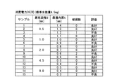
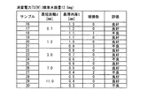
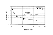
図4は、消費電力39[W]の金属蒸気放電ランプについての安全性の評価結果を示す図である。図5は、消費電力73[W]の金属蒸気放電ランプについての安全性の評価結果を示す図である。   FIG. 4 is a diagram showing a safety evaluation result for a metal vapor discharge lamp with a power consumption of 39 [W]. FIG. 5 is a diagram showing a safety evaluation result for a metal vapor discharge lamp with a power consumption of 73 [W].

図4に示すように、消費電力39[W]のランプに関し、最短距離dが0.5[mm]の場合は最薄肉厚tが1.3[mm]以上で(サンプル2)、最短距離dが1.0[mm]の場合は最薄肉厚tが1.0[mm]以上で(サンプル5)、最短距離dが2.0[mm]の場合は最薄肉厚tが0.7[mm]以上で(サンプル8)、最短距離dが4.5[mm]の場合は最薄肉厚tが0.5[mm]以上で(サンプル11)、最短距離dが9.0[mm]の場合は最薄肉厚tが0.4[mm]以上で(サンプル14)、それぞれ「良好」との評価が得られた。なお、図4に示す評価結果は消費電力39[W]のランプについてのものであるが、消費電力、アーク長および水銀量が上記範囲内に規定される定格電力35[W]タイプのランプに関しては、いずれも消費電力39[W]のランプと同様の結果が得られた。   As shown in FIG. 4, regarding the lamp with power consumption of 39 [W], when the shortest distance d is 0.5 [mm], the thinnest thickness t is 1.3 [mm] or more (sample 2), and the shortest distance When d is 1.0 [mm], the thinnest thickness t is 1.0 [mm] or more (Sample 5), and when the shortest distance d is 2.0 [mm], the thinnest thickness t is 0.7. When [mm] or more (sample 8) and the shortest distance d is 4.5 [mm], the thinnest thickness t is 0.5 [mm] or more (sample 11) and the shortest distance d is 9.0 [mm]. ], The thinnest wall thickness t was 0.4 [mm] or more (Sample 14), and an evaluation of “good” was obtained. The evaluation results shown in FIG. 4 are for a lamp with a power consumption of 39 [W], but for a lamp with a rated power of 35 [W] type in which the power consumption, arc length and mercury amount are defined within the above ranges. Both obtained the same results as the lamps with a power consumption of 39 [W].

また、図5に示すように、消費電力73[W]のランプに関し、最短距離dが0.7[mm]の場合は最薄肉厚tが1.2[mm]以上で(サンプル17)、最短距離dが1.2[mm]の場合は最薄肉厚tが1.0[mm]以上で(サンプル20)、最短距離dが3.0[mm]の場合は最薄肉厚tが0.7[mm]以上で(サンプル23)、最短距離dが7.0[mm]の場合は最薄肉厚tが0.5[mm]以上で(サンプル26)、最短距離dが11.0[mm]の場合は最薄肉厚tが0.4[mm]以上で(サンプル29)、それぞれ「良好」との評価が得られた。なお、図5に示す評価結果は消費電力73[W]のランプについてのものであるが、消費電力、アーク長および水銀量が上記範囲内に規定される定格電力70[W]タイプのランプに関しては、いずれも消費電力73[W]のランプと同様の結果が得られた。   Further, as shown in FIG. 5, regarding the lamp with power consumption 73 [W], when the shortest distance d is 0.7 [mm], the thinnest thickness t is 1.2 [mm] or more (Sample 17), When the shortest distance d is 1.2 [mm], the thinnest thickness t is 1.0 [mm] or more (Sample 20), and when the shortest distance d is 3.0 [mm], the thinnest thickness t is 0. When the shortest distance d is 7.0 [mm] when the distance is 7 [mm] or more (sample 23), the thinnest thickness t is 0.5 [mm] or more (sample 26), and the shortest distance d is 11.0. In the case of [mm], the thinnest thickness t was 0.4 [mm] or more (Sample 29), and evaluations of “good” were obtained. The evaluation results shown in FIG. 5 are for a lamp with a power consumption of 73 [W], but for a lamp with a rated power of 70 [W] type in which the power consumption, arc length and mercury amount are defined within the above ranges. Both obtained the same results as the lamps with power consumption of 73 [W].

図6は、定格電力35[W]タイプの金属蒸気放電ランプについて外管破損が生じ難い条件を説明するための図である。定格電力35[W]タイプのランプに関し、X軸に最短距離dをとり、Y軸に最薄肉厚tをとったXY直交座標上に、サンプル2,5,8,11,14の値をプロットすると、t≧d−0.4で表すことのできる回帰曲線が得られた。FIG. 6 is a diagram for explaining conditions under which the outer tube is not easily damaged in the rated power 35 [W] type metal vapor discharge lamp. For lamps with a rated power of 35 [W], the values of samples 2, 5, 8, 11, and 14 are plotted on XY Cartesian coordinates with the shortest distance d on the X axis and the thinnest wall thickness t on the Y axis. Then, a regression curve that can be expressed by t ≧ d −0.4 was obtained.

図7は、定格電力70[W]タイプの金属蒸気放電ランプについて外管破損が生じ難い条件を説明するための図である。同様に、定格電力70[W]タイプのランプに関し、サンプル17,20,23,26,29の値をプロットすると、t≧1.1×d−0.4で表すことのできる回帰曲線が得られた。FIG. 7 is a view for explaining the conditions under which the outer tube is not easily damaged in the rated power 70 [W] type metal vapor discharge lamp. Similarly, when the values of samples 17, 20, 23, 26, and 29 are plotted for a lamp with a rated power of 70 [W], a regression curve that can be expressed as t ≧ 1.1 × d− 0.4 is obtained. It was.

この結果から、最短距離dと最薄肉厚tとが、t≧1.1×d−0.4で表すことのできる回帰曲線よりも上方の領域(回帰曲線上を含む)に該当する関係を満たしていれば、外管の破損が生じないことが分かった。さらに、少なくとも定格電力35[W]タイプの場合と定格電力70[W]タイプの場合とで回帰曲線が略一致したことから、最短距離dと最薄肉厚tとの関係に対して定格電力は影響が小さいことがわかった。From this result, the relationship in which the shortest distance d and the thinnest thickness t correspond to a region (including the regression curve) above the regression curve that can be expressed by t ≧ 1.1 × d− 0.4. If it is satisfied, it was found that the outer tube was not damaged. Furthermore, since the regression curves substantially coincided with at least the rated power of 35 [W] type and the rated power of 70 [W] type, the rated power is the relationship between the shortest distance d and the thinnest thickness t. It turns out that the influence is small.

今回の定格電力の範囲では、安定点灯時の消費電力、アーク長および水銀量の違いによる影響が小さい。放電管破損は、安定点灯後に回路が短絡することによって発光管に流れる電流が瞬間的に大きなって発光管内の圧力が急上昇し、放電管構造を維持する臨界を超えたときに発生するためである。よって、外管の破損は、安定点灯時の消費電力、アーク長および水銀量よりも主として内管の材料・寸法形状及び外管の材料・寸法形状によって決定される。   Within the current rated power range, the effects of power consumption, arc length, and mercury content during stable lighting are small. The discharge tube breaks down when the circuit is short-circuited after stable lighting and the current flowing through the arc tube is momentarily large, causing the pressure in the arc tube to rise rapidly and exceeding the criticality for maintaining the discharge tube structure. is there. Therefore, the breakage of the outer tube is mainly determined by the material / dimension shape of the inner tube and the material / dimension shape of the outer tube rather than the power consumption, the arc length, and the mercury amount during stable lighting.

なお、上記実験結果は外管300が硬質ガラスで構成されている場合のものであるが、当該実験結果は、少なくとも石英ガラスまたはアルミナセラミックで構成された外管300にも適用可能である。その理由として、石英ガラスのヤング率は硬質ガラスのヤング率と同じ位であり、アルミナセラミックのヤング率は硬質ガラスのヤング率よりも大きいことが挙げられる。   In addition, although the said experimental result is a thing when the outer tube | pipe 300 is comprised by hard glass, the said experimental result is applicable also to the outer tube | pipe 300 comprised at least by quartz glass or an alumina ceramic. The reason is that the Young's modulus of quartz glass is about the same as the Young's modulus of hard glass, and the Young's modulus of alumina ceramic is larger than the Young's modulus of hard glass.

ヤング率とは、応力と歪みの大きさとの比であり、ヤング率が大きい材料ほど弾性変形により衝撃を吸収し難い。このことから、ヤング率が硬質ガラスと同じ位である石英ガラスで外管300が構成されている場合は、硬質ガラスで外管300が構成されている場合と同様の実験結果が得られるものと推測できる。また、ヤング率が硬質ガラスよりも大きいアルミナセラミックで外管300が構成されている場合は、硬質ガラスで外管300が構成されている場合よりも、安全性が高くなると推測できる。   The Young's modulus is a ratio between the stress and the magnitude of strain. A material having a higher Young's modulus is less likely to absorb impact due to elastic deformation. From this, when the outer tube 300 is made of quartz glass whose Young's modulus is the same as that of hard glass, the same experimental results as when the outer tube 300 is made of hard glass can be obtained. I can guess. Moreover, when the outer tube 300 is made of alumina ceramic having a Young's modulus larger than that of hard glass, it can be estimated that the safety is higher than when the outer tube 300 is made of hard glass.

また、上記実験結果は内管200が石英ガラスで構成されている場合のものであるが、当該実験結果は、少なくとも硬質ガラスまたはアルミナセラミックで構成された内管200にも適用可能である。その理由として、硬質ガラスの密度は石英ガラスの密度と同じ約2.2g/cmであり、アルミナセラミックの密度は石英ガラスの密度よりも大きい約3.6g/cmであることが挙げられる。Moreover, although the said experimental result is a thing when the inner tube | pipe 200 is comprised with quartz glass, the said experimental result is applicable also to the inner tube | pipe 200 comprised at least with hard glass or an alumina ceramic. The reason is that the density of hard glass is about 2.2 g / cm 3, which is the same as that of quartz glass, and the density of alumina ceramic is about 3.6 g / cm 3, which is larger than the density of quartz glass. .

放電管100が破裂したときに、内管200の放電管近傍部分が割れると、飛散破片(内管200の先端部202)が外管503の閉塞部506に向かって吹き飛ぶ。飛散破片の大きさは内管200を構成する材料に依存せず、ほぼ同じであるという知見を発明者らは実験から得ている。放電管100が破裂によって飛散破片が受ける衝撃は、破裂によって生じた力の大きさfと力を受けた時間△tの積で表され、飛散破片の質量mと速度vの積である運動量として飛散破片に付与される。すなわち、飛散破裂の速度vは、破裂によって生じた力f及び力を受けた時間△tに比例し、飛散破片の質量に反比例する。破裂によって生じた力fは、詳細にいえば破裂によって加えられた圧力を飛散破片の内面にわたって積分したものである。飛散破片の大きさが内管200を構成する材料に依存しないため、破裂によって生じた力の大きさfもまた内管200を構成する材料に依存しない。また、力を受けた時間△tに関しては、主に放電管100の破裂によって生じたガス流の伝播によって決まり一概にはいえないが、少なくとも本願の構成のように内管200の材料が硬質ガラス、石英ガラス、あるいはアルミナセラミックである場合にはほぼ同じであると推測する。これらのことから、内管200の飛散破片に付与される運動量は、内管200を構成する材料に依存しないことが考えられる。一方、内管200を構成する材料の密度が大きいほど飛散破片の質量mは大きいことから、内管200を石英ガラスで構成した場合よりも、密度の大きいアルミナセラミックで構成した場合よりも飛散破片の速度は遅くなり、飛散破片が外管300に到達するまでの時間は長くなる。そうすると、破裂した放電管100内の封入ガスは飛散破片よりも先に外管300に到達するため、外管300の内面304に跳ね返ってきた封入ガスにより飛散破片が押し戻され、これにより破片の速度低下が生じる。その結果、アルミナセラミックで内管200が構成されている場合の方が、石英ガラスで内管200が構成されている場合よりも、安全性が高くなると推測できる。また、石英ガラスで内管200が構成されている場合と硬質ガラスで内管200が構成されている場合とを比べると、硬質ガラスと石英ガラスとは密度が同じであることから、飛散破片の速度も同じ位であると考えられ、実験結果も同様になると推測できる。   When the discharge tube 100 is ruptured and the portion near the discharge tube of the inner tube 200 is cracked, the scattered fragments (the tip portion 202 of the inner tube 200) are blown toward the closed portion 506 of the outer tube 503. The inventors have found from experiments that the size of the scattered pieces does not depend on the material constituting the inner tube 200 and is substantially the same. The impact received by the shattered fragments due to the burst of the discharge tube 100 is represented by the product of the magnitude f of the burst f and the time Δt when the force is received, and the momentum is the product of the mass m of the shattered fragments and the velocity v. It is given to scattered pieces. In other words, the scattering burst speed v is proportional to the force f generated by the burst and the time Δt when the force is received, and inversely proportional to the mass of the scattered fragments. Specifically, the force f generated by the burst is obtained by integrating the pressure applied by the burst over the inner surface of the scattered fragments. Since the size of the scattered pieces does not depend on the material constituting the inner tube 200, the magnitude f of the force generated by the rupture does not depend on the material constituting the inner tube 200. Further, the time Δt during which the force is received is determined mainly by the propagation of the gas flow generated by the bursting of the discharge tube 100, and cannot be generally stated, but at least the material of the inner tube 200 is hard glass as in the configuration of the present application. In the case of quartz glass or alumina ceramic, it is assumed that they are almost the same. From these facts, it is conceivable that the momentum imparted to the scattered pieces of the inner tube 200 does not depend on the material constituting the inner tube 200. On the other hand, the larger the density of the material constituting the inner tube 200, the larger the mass m of the scattered fragments. Therefore, the scattered fragments are larger than the case where the inner tube 200 is made of a higher density alumina ceramic than the case where the inner tube 200 is made of quartz glass. And the time until the scattered fragments reach the outer tube 300 becomes longer. Then, since the encapsulated gas in the ruptured discharge tube 100 reaches the outer tube 300 earlier than the scattered fragments, the scattered fragments are pushed back by the encapsulated gas bounced back to the inner surface 304 of the outer tube 300, and thereby the speed of the fragments. A decrease occurs. As a result, it can be inferred that safety is higher in the case where the inner tube 200 is made of alumina ceramic than in the case where the inner tube 200 is made of quartz glass. In addition, when the case where the inner tube 200 is made of quartz glass and the case where the inner tube 200 is made of hard glass are compared, the density of the hard glass and the quartz glass is the same. The speed is considered to be about the same, and it can be assumed that the experimental results are the same.

なお、飛散破片の大きさは定格電力35[W]タイプと定格電力70[W]タイプとで略同じである。したがって、定格電力35[W]タイプと定格電力70[W]タイプとで同様の実験結果が得られると推測できる。   In addition, the size of the scattered fragments is substantially the same for the rated power 35 [W] type and the rated power 70 [W] type. Therefore, it can be estimated that the same experimental result is obtained with the rated power 35 [W] type and the rated power 70 [W] type.

次に、内管の先端部および外管の閉塞部の形状が外管破損に及ぼす影響を調べた。図8は、内管の先端部および外管の閉塞部の形状が外管破損に及ぼす影響を説明するための図である。   Next, the influence of the shapes of the distal end portion of the inner tube and the closed portion of the outer tube on the outer tube was examined. FIG. 8 is a diagram for explaining the influence of the shape of the distal end portion of the inner tube and the closed portion of the outer tube on the outer tube breakage.

図8に示すように、定格電力35[W]タイプのランプであるサンプル11について、水銀量を4.5[mg]から5.0[mg]に増量して安全性を評価したところ、外管の破損数は4本中0本から4本中1本に増加した。さらに、水銀量を4.5[mg]から5.5[mg]に増量したところ、外管の破損数は4本中2本に増加した。また、定格電力70[W]タイプのランプであるサンプル25について、水銀量を12.5[mg]から13.0[mg]に増量して安全性を評価したところ、外管の破損数は4本中0本から4本中2本に増加した。さらに、水銀量を12.5[mg]から13.5[mg]に増量したところ、外管の破損数は4本中3本に増加した。   As shown in FIG. 8, the safety of the sample 11 which is a lamp of rated power 35 [W] type was evaluated by increasing the mercury amount from 4.5 [mg] to 5.0 [mg]. The number of tube failures increased from 0 in 4 to 1 in 4. Furthermore, when the amount of mercury was increased from 4.5 [mg] to 5.5 [mg], the number of outer tube failures increased to two out of four. In addition, the safety of the sample 25, which is a rated power 70 [W] type lamp, was evaluated by increasing the mercury amount from 12.5 [mg] to 13.0 [mg]. Increased from 0 out of 4 to 2 out of 4. Furthermore, when the mercury content was increased from 12.5 [mg] to 13.5 [mg], the number of outer tube failures increased to 3 out of 4.

ところが、サンプル11について、チップオフ部の形状はそのままとし、内管の先端部の形状を図2に示すような略板状から略半球状に変更したところ、水銀量が5.0[mg]であるにも拘わらず、外管の破損数が4本中0本になり、外管がより破損し難くなった。但し、水銀量が5.5[mg]の場合は、内管の先端部の形状を略半球状に変更しても4本中1本の外管が破損した。また、サンプル25についても、内管の先端部の形状を略半球状に変更したところ、水銀量が13.0[mg]であるにも拘わらず、外管の破損数は4本中0本になり、外管がより破損し難くなった。但し、水銀量が13.5[mg]の場合は、内管の先端部の形状を略半球状に変更しても4本中3本の外管が破損した。   However, with respect to sample 11, the shape of the tip-off portion was left as it was, and the shape of the tip of the inner tube was changed from a substantially plate shape as shown in FIG. 2 to a substantially hemispherical shape. As a result, the mercury amount was 5.0 [mg]. Despite this, the number of breakage of the outer tube became 0 out of 4 and the outer tube became more difficult to break. However, when the amount of mercury was 5.5 [mg], one of the four outer tubes was damaged even when the shape of the tip of the inner tube was changed to a substantially hemispherical shape. For sample 25, when the shape of the tip of the inner tube was changed to a substantially hemispherical shape, the number of breakage of the outer tube was 0 out of 4 even though the mercury amount was 13.0 [mg]. As a result, the outer tube became more difficult to break. However, when the mercury amount was 13.5 [mg], three of the four outer tubes were damaged even when the shape of the tip of the inner tube was changed to a substantially hemispherical shape.

次に、外管の閉塞部の内面を、図2に示すような曲率半径R[mm]が8.0未満の曲面から、チップオフ部の形状はそのままとし、曲率半径R[mm]が8.0以上の曲面または略平面に変更し、さらに、内管の先端部の形状も略半球状に変更したところ、サンプル11について、水銀量が5.0[mg]および5.5[mg]のいずれの場合も、外管の破損数が4本中0本になり、外管がさらに破損し難くなった。また、サンプル25について、水銀量が13.0[mg]および13.5[mg]のいずれの場合も、外管の破損数が4本中0本になり、外管がさらに破損し難くなった。   Next, the inner surface of the closed portion of the outer tube is curved from a curved surface having a radius of curvature R [mm] of less than 8.0 as shown in FIG. 2, and the shape of the tip-off portion is kept as it is, and the radius of curvature R [mm] is 8 When the sample was changed to a curved surface of approximately 0 or more or a substantially flat surface, and the shape of the tip of the inner tube was also changed to a substantially hemispherical shape, the mercury content of Sample 11 was 5.0 [mg] and 5.5 [mg]. In either case, the number of breakage of the outer tube became 0 out of 4, and the outer tube became more difficult to break. For sample 25, when the mercury amount is 13.0 [mg] and 13.5 [mg], the number of breakage of the outer tube is 0 out of 4, and the outer tube is further less likely to break. It was.

内管の先端部が略半球状である場合や、外管の閉塞部の内面が曲率半径R[mm]が8.0以上の曲面または略平面の場合は、内管200の先端部202のコーナー部分206から外管300の閉塞部302の内面304までのランプ軸X方向における距離が長くなる。その距離が最短距離dであったために、結果的に最短距離dが長くなったことになり、外管300がより破損し難くなったと考えられる。また、外管の閉塞部の内面が曲率半径R[mm]が8.0以上の曲面、または略平面の場合は、外管の閉塞部の歪が小さくなる。このことによっても、外管が破損し難くなったと考えられる。   When the distal end portion of the inner tube is substantially hemispherical, or when the inner surface of the closed portion of the outer tube is a curved surface or substantially flat surface having a curvature radius R [mm] of 8.0 or more, the distal end portion 202 of the inner tube 200 The distance in the lamp axis X direction from the corner portion 206 to the inner surface 304 of the closing portion 302 of the outer tube 300 is increased. Since the distance is the shortest distance d, the shortest distance d is consequently increased, and it is considered that the outer tube 300 is more difficult to break. Further, when the inner surface of the closed portion of the outer tube is a curved surface having a radius of curvature R [mm] of 8.0 or more, or a substantially flat surface, the distortion of the closed portion of the outer tube is reduced. This also seems to have prevented the outer tube from being damaged.

以上、本発明に係る金属蒸気放電ランプおよび照明装置を実施の形態に基づいて具体的に説明してきたが、本発明に係る金属蒸気放電ランプおよび照明装置は、上記の実施の形態に限定されないことはいうまでもない。なお、上記実施の形態と同様の構成部材には、上記実施の形態と同様の符号を付し、その説明を省略する。   As described above, the metal vapor discharge lamp and the lighting device according to the present invention have been specifically described based on the embodiments. However, the metal vapor discharge lamp and the lighting device according to the present invention are not limited to the above embodiments. Needless to say. In addition, the same code | symbol as the said embodiment is attached | subjected to the structural member similar to the said embodiment, and the description is abbreviate | omitted.

(変形例1)
例えば、内管200は、図9に示すように、口金400の外管側端部405に設けたホルダ12で封止部201を保持することにより支持されていても良い。ホルダ12は口金400の一部である。ホルダ12には封止部201の形状にあわせた差込口(不図示)が設けられており、その差込口に封止部201の先端を差し込むことによって、封止部201は口金400に保持される。
(Modification 1)
For example, as shown in FIG. 9, the inner tube 200 may be supported by holding the sealing portion 201 with the holder 12 provided at the outer tube side end 405 of the base 400. The holder 12 is a part of the base 400. The holder 12 is provided with an insertion port (not shown) that matches the shape of the sealing portion 201, and the sealing portion 201 is attached to the base 400 by inserting the tip of the sealing portion 201 into the insertion port. Retained.

この場合、ホルダ12を口金400に固定する前にホルダ12に封止部201を固定することで、封止部201の固定と、内管200の第2のリード線126,127の口金400への固定とを別々に行うことができ、ランプを組立やすくすることができる。ホルダ12には、その外周面に鍔形状の大径部12aが設けられ、大径部12aが口金400の外管側の端部405に係止されている。なお、例えば、大径部12aの口金400とは反対側(ランプ頂部側)に外管300の開口部301を当接する等して、外管300をホルダ12に固定しても良い。   In this case, by fixing the sealing part 201 to the holder 12 before fixing the holder 12 to the base 400, the fixing of the sealing part 201 and the base 400 of the second lead wires 126 and 127 of the inner tube 200 are performed. Can be performed separately, and the lamp can be easily assembled. The holder 12 is provided with a bowl-shaped large-diameter portion 12 a on the outer peripheral surface thereof, and the large-diameter portion 12 a is locked to the end portion 405 of the base 400 on the outer tube side. For example, the outer tube 300 may be fixed to the holder 12 by abutting the opening 301 of the outer tube 300 on the side opposite to the base 400 (the lamp top side) of the large diameter portion 12a.

(変形例2)
また、図10に示すように、内管200の封止部201は、当該封止部201と外管300との間に配置された鍔状部材13によっても支持されていても良い。図10に示すように、内管200の封止部201には鍔状部材13が外嵌されている。
(Modification 2)
Further, as shown in FIG. 10, the sealing portion 201 of the inner tube 200 may be supported also by the flange-shaped member 13 disposed between the sealing portion 201 and the outer tube 300. As shown in FIG. 10, the hook-shaped member 13 is fitted on the sealing portion 201 of the inner tube 200.

外管300の開口部301は、口金400に対して外接しているため、内管と外管との隙間にセメント等の接着剤を充填する工程中に、特殊な冶具を用いることなく接着剤の充填具合を外側から確認することができる。   Since the opening 301 of the outer pipe 300 is circumscribed with respect to the base 400, the adhesive is used without using a special jig during the process of filling the gap between the inner pipe and the outer pipe with an adhesive such as cement. The filling condition can be confirmed from the outside.

鍔状部材13の口金側には接着剤600が充填されており、例えば鍔状部材13の口金側主面13aは接着剤600によってランプ10の外側から見えないようになっている。一方、鍔状部材13の放電管側には接着剤600が充填されておらず、鍔状部材13の放電管側主面13bはランプ10の外側から見える。外側から見えない口金側主面13aの態様は任意であるが、外側から見える放電管側主面13bは、ランプ10の外観を良好にするために平面であることが好ましい。なお、鍔状部材13の厚みは、必ずしも略均一である必要はなく不均一であっても良い。例えば、外側から見える放電管側主面13bだけが平面で口金側主面13aは平面でない構成であっても良い。さらに、鍔状部材13は、略板状に限定されず、膜状、ブロック状等の他の形状であっても良い。   An adhesive 600 is filled on the base side of the bowl-shaped member 13. For example, the base-side main surface 13 a of the bowl-shaped member 13 is not visible from the outside of the lamp 10 by the adhesive 600. On the other hand, the adhesive 600 is not filled on the discharge tube side of the bowl-shaped member 13, and the discharge tube side main surface 13 b of the bowl-shaped member 13 can be seen from the outside of the lamp 10. The mode of the base side main surface 13 a that cannot be seen from the outside is arbitrary, but the discharge side main surface 13 b that can be seen from the outside is preferably a flat surface in order to improve the appearance of the lamp 10. Note that the thickness of the bowl-shaped member 13 does not necessarily have to be substantially uniform, and may be non-uniform. For example, only the discharge tube side main surface 13b visible from the outside may be a flat surface and the base side main surface 13a may not be a flat surface. Furthermore, the hook-shaped member 13 is not limited to a substantially plate shape, and may have other shapes such as a film shape and a block shape.

図11は、本発明の一態様に係る鍔状部材を示す斜視図である。図11に示すように、鍔状部材13の略中央には、封止部201の形状に合わせた孔部13cが形成されている。孔部13cの形状は、封止部201をランプ軸Xと直交する面で切断したときの横断面の形状と略同一であって、鍔状部材13を封止部201に外嵌させた状態で、孔部13cの内周面13dと封止部201の表面207とが内周面13dの略全周に亘って近接しており、とりわけ接触していることが好ましい。   FIG. 11 is a perspective view illustrating a hook-shaped member according to one embodiment of the present invention. As shown in FIG. 11, a hole 13 c that matches the shape of the sealing portion 201 is formed in the approximate center of the bowl-shaped member 13. The shape of the hole 13c is substantially the same as the shape of the cross section when the sealing portion 201 is cut along a plane orthogonal to the lamp axis X, and the collar member 13 is externally fitted to the sealing portion 201. Therefore, it is preferable that the inner peripheral surface 13d of the hole 13c and the surface 207 of the sealing portion 201 are close to each other over substantially the entire circumference of the inner peripheral surface 13d, and are particularly in contact with each other.

なお、鍔状部材13の孔部13cは、必ずしも封止部201と略同一の形状である必要はなく、ある程度の範囲であれば、封止部201の横断面と異なる形状であっても良い。   The hole 13c of the bowl-shaped member 13 does not necessarily have the same shape as the sealing portion 201, and may have a shape different from the cross section of the sealing portion 201 as long as it is within a certain range. .

例えば、孔部13cの形状が封止部201の横断面よりも、全体的に或いは部分的にひとまわり小さい形状であっても良い。その場合は、鍔状部材13を塑性もしくは弾性を有して変形可能な材料、好ましくは更に耐熱性を有する材料で形成すれば、封止部201に外嵌可能である。このような構成であれば、孔部13c内に封止部201を圧入することになるため、封止部201に対して鍔状部材13が位置ずれし難い。また、孔部13cの内周面13dと封止部201の表面207とがより密着することになるため、接着剤600が漏れるような隙間が鍔状部材13と封止部201との間に生じ難い。   For example, the shape of the hole 13c may be smaller than the cross section of the sealing portion 201 in whole or in part. In that case, if the flange-shaped member 13 is formed of a plastically or elastically deformable material, preferably a heat-resistant material, it can be externally fitted to the sealing portion 201. With such a configuration, since the sealing portion 201 is press-fitted into the hole portion 13c, the flange-shaped member 13 is not easily displaced with respect to the sealing portion 201. In addition, since the inner peripheral surface 13d of the hole 13c and the surface 207 of the sealing portion 201 are more closely attached, a gap through which the adhesive 600 leaks is between the flange-shaped member 13 and the sealing portion 201. It is hard to occur.

また、例えば、孔部13cの形状が封止部201の横断面よりも、全体的に或いは部分的にひとまわり大きい形状であっても良い。その場合は、孔部13cの内周面13dの一部が封止部201の表面207と接触していない構成、または、孔部13cの内周面13dが封止部201の表面207と全く接触していない構成となり得る。内周面13dの一部が接触していない構成の場合は、接触している部分において鍔状部材13が封止部201に保持されていれば良い。但し、接触していない部分に生じる隙間は接着剤600が漏れ難い狭い幅であることが好ましく、その隙間の最大幅は1.0 [mm]以下であることが好ましい。一方、鍔状部材13と封止部201とが全く接触しない構成の場合は、接着剤などで鍔状部材13を封止部201に固定することが考えられる。その場合の接着剤は、封止部201と外管300とを接合する接着剤600であっても良い。   Further, for example, the shape of the hole 13c may be a shape that is slightly larger than the cross section of the sealing portion 201, either entirely or partially. In that case, a part of the inner peripheral surface 13d of the hole 13c is not in contact with the surface 207 of the sealing portion 201, or the inner peripheral surface 13d of the hole 13c is not at all with the surface 207 of the sealing portion 201. It can be the structure which is not contacting. In the case of a configuration in which a part of the inner peripheral surface 13d is not in contact, the hook-shaped member 13 only needs to be held by the sealing portion 201 in the contacted portion. However, the gap generated in the non-contact portion is preferably a narrow width that prevents the adhesive 600 from leaking, and the maximum width of the gap is preferably 1.0 [mm] or less. On the other hand, when the hook-shaped member 13 and the sealing portion 201 are not in contact with each other, the hook-shaped member 13 may be fixed to the sealing portion 201 with an adhesive or the like. The adhesive in that case may be an adhesive 600 that joins the sealing portion 201 and the outer tube 300.

次に、鍔状部材13は、外管300の内周面の形状に沿った外周形状を有し、鍔状部材13の外径と外管300の内径とは略同一である。内管200を外管300内に収容した状態において、鍔状部材13の外周面13eと外管300の内周面とが外周面13eの略全周に亘って接触している。   Next, the hook-shaped member 13 has an outer peripheral shape that follows the shape of the inner peripheral surface of the outer tube 300, and the outer diameter of the hook-shaped member 13 and the inner diameter of the outer tube 300 are substantially the same. In a state where the inner tube 200 is housed in the outer tube 300, the outer peripheral surface 13e of the bowl-shaped member 13 and the inner peripheral surface of the outer tube 300 are in contact with each other over substantially the entire periphery of the outer peripheral surface 13e.

なお、鍔状部材13の外径は、必ずしも外管300の内径と略同一である必要はなく、ある程度の範囲であれば、外管300の内径と異なる大きさであっても良い。   Note that the outer diameter of the bowl-shaped member 13 is not necessarily the same as the inner diameter of the outer tube 300, and may be different from the inner diameter of the outer tube 300 as long as it is within a certain range.

例えば、鍔状部材13の外径が外管300の内径より大きくても良い。鍔状部材13を塑性もしくは弾性を有して変形可能な材料、好ましくは更に耐熱性を有する材料で形成すれば、鍔状部材13を外管300内に配置可能である。その場合は、外管300内に鍔状部材13が圧入されることになるため、鍔状部材13の外周面13eと外管300の内周面とを密着させることができ、鍔状部材13と外管300との間に接着剤600が漏れるような隙間が生じ難い。   For example, the outer diameter of the bowl-shaped member 13 may be larger than the inner diameter of the outer tube 300. If the hook-shaped member 13 is formed of a plastic or elastic deformable material, preferably a heat-resistant material, the hook-shaped member 13 can be disposed in the outer tube 300. In that case, since the hook-shaped member 13 is press-fitted into the outer tube 300, the outer peripheral surface 13e of the hook-shaped member 13 and the inner peripheral surface of the outer tube 300 can be brought into close contact with each other. And the outer tube 300 are less likely to cause a gap that causes the adhesive 600 to leak.

また、例えば、鍔状部材13の外径が外管300の内径より小さく、外周面13eが全周に亘って外管300の内周面と接触していない場合であっても良い。その場合、外周面13eと外管300との間に生じる隙間は、接着剤600の漏れ難い幅であることが好ましく、その隙間の最大幅は1.0[mm]以下であることが好ましい。   Further, for example, the outer diameter of the bowl-shaped member 13 may be smaller than the inner diameter of the outer tube 300, and the outer peripheral surface 13e may not be in contact with the inner peripheral surface of the outer tube 300 over the entire circumference. In this case, the gap generated between the outer peripheral surface 13e and the outer tube 300 is preferably a width that prevents the adhesive 600 from leaking, and the maximum width of the gap is preferably 1.0 [mm] or less.

さらに、鍔状部材13が、略円形板状ではなく、例えば多角形板状等である場合は、鍔状部材13の外周面13eの一部のみが外管300の内周面と接触する構成となり得る。その場合は、外周面13eと外管300との間に生じる隙間は、接着剤600の漏れ難い幅であることが好ましく、その隙間の最大幅は1.5[mm]以下であることが好ましい。   Furthermore, when the bowl-shaped member 13 is not a substantially circular plate shape but a polygonal plate shape, for example, only a part of the outer circumferential surface 13e of the bowl-shaped member 13 is in contact with the inner circumferential surface of the outer tube 300. Can be. In that case, the gap formed between the outer peripheral surface 13e and the outer tube 300 is preferably a width that prevents the adhesive 600 from leaking, and the maximum width of the gap is preferably 1.5 [mm] or less. .

鍔状部材13は、外管300および内管200を傷つけないために、外管300および内管200よりも硬度が低いことが好ましい。また、ランプ10の点灯時には封止部201が高温になるため、鍔状部材13は耐熱温度が150[℃]以上、より好ましくは200[℃]以上、さらに好ましくは250[℃]以上であることが好ましい。さらに鍔状部材13の少なくとも孔部13c周辺を構成する材料が、塑性もしくは弾性を有して変形可能であれば、鍔状部材13の外径が外管300の内径より大きくても圧入することが可能である。これら硬度、耐熱温度および変形可能性の観点から、鍔状部材13の材料としては、アルミニウム、ステンレス等の金属や、マイカ、ガラス等の鉱物などが好適である。また、鍔状部材は必ずしも板状でなくとも、接着剤600が漏れ難いものである限り、たとえば細かい網目をなす金属やガラス繊維であっても良い。   The bowl-shaped member 13 preferably has a lower hardness than the outer tube 300 and the inner tube 200 in order not to damage the outer tube 300 and the inner tube 200. Moreover, since the sealing part 201 becomes high temperature when the lamp 10 is turned on, the heat resistant temperature of the bowl-shaped member 13 is 150 [° C.] or more, more preferably 200 [° C.] or more, and further preferably 250 [° C.] or more. It is preferable. Further, if the material constituting at least the periphery of the hole 13c of the hook-shaped member 13 is plastic or elastic and can be deformed, it can be press-fitted even if the outer diameter of the hook-shaped member 13 is larger than the inner diameter of the outer tube 300. Is possible. From the viewpoints of hardness, heat-resistant temperature, and deformability, the material of the bowl-shaped member 13 is preferably a metal such as aluminum or stainless steel, or a mineral such as mica or glass. Further, the hook-like member is not necessarily a plate shape, but may be, for example, a metal or glass fiber having a fine mesh as long as the adhesive 600 is difficult to leak.

鍔状部材13は、上記した役割を果たすだけでなく、内管200に対する外管300の姿勢を規制し、内管200の管軸と外管300の管軸とを一致させるための部材としても利用可能である。その場合は、鍔状部材13が封止部201および外管300と接触することが好ましい。   The bowl-shaped member 13 not only plays the above-described role, but also regulates the posture of the outer tube 300 with respect to the inner tube 200 and serves as a member for matching the tube axis of the inner tube 200 with the tube axis of the outer tube 300. Is available. In that case, it is preferable that the bowl-shaped member 13 is in contact with the sealing portion 201 and the outer tube 300.

内管200の封止部201と外管300とは、鍔状部材13よりも口金側に配置された接着剤600によって接合されている。また、外管300と口金400も、接着剤600により接合されている。さらに、封止部201と口金400も接着剤600により接合されていると、ランプ10を構成する各部材の保持強度が高められ、落下等の耐衝撃性が上がるため、より好ましい。   The sealing portion 201 of the inner tube 200 and the outer tube 300 are joined together by an adhesive 600 disposed on the base side with respect to the flange-shaped member 13. Further, the outer tube 300 and the base 400 are also joined by an adhesive 600. Further, it is more preferable that the sealing portion 201 and the base 400 are also joined by the adhesive 600 because the holding strength of each member constituting the lamp 10 is increased and the impact resistance such as dropping is increased.

なお、接着剤600としては、セメントなどが考えられる。また、接着剤600は、少なくとも封止部201と外管300とを接合していれば良く、外管300と口金400、および、封止部201と口金400は、別の接着剤や金属部材等の別の接合構造により接合されていても良いし、
接着剤600は、鍔状部材13の口金側に充填されている。接着剤600の充填は、仮組みしたランプ10を上側に口金400が位置するよう保持し、口金400の貫通孔403から口金400の内部に充填機のノズル(不図示)を差し込んで、そのノズルから内管200の封止部201と外管300との隙間に接着剤600を注入して行なわれる。
In addition, as the adhesive 600, cement etc. can be considered. The adhesive 600 only needs to join at least the sealing portion 201 and the outer tube 300, and the outer tube 300 and the base 400, and the sealing portion 201 and the base 400 are different adhesives or metal members. It may be joined by another joining structure such as
The adhesive 600 is filled on the base side of the bowl-shaped member 13. The adhesive 600 is filled by holding the temporarily assembled lamp 10 so that the base 400 is positioned on the upper side, and inserting a nozzle (not shown) of the filling machine into the base 400 from the through hole 403 of the base 400. The adhesive 600 is injected into the gap between the sealing portion 201 of the inner tube 200 and the outer tube 300.

接着剤600は、固化する前の流動性を有する状態において、下方に垂れる、すなわち放電管側に流れるのが、鍔状部材13よって堰き止められている。そのため、接着剤600は、外管300内における鍔状部材13よりも口金側において鍔状部材13によって堰き止められた状態で固化している。   The adhesive 600 is dammed by the hook-shaped member 13 so as to hang downward, that is, to flow to the discharge tube side in a state having fluidity before solidifying. Therefore, the adhesive 600 is solidified in a state where it is blocked by the hook-shaped member 13 on the base side of the hook-shaped member 13 in the outer tube 300.

接着剤600は、鍔状部材13によって堰き止められているため、封止部201を超えて放電管100側へ流れることがなく、ランプ10は外観が良好である。また、接着剤600は放電管100側が鍔状部材13によってランプ軸X方向の高さレベルが揃っているため、ランプ10の外観が良好である。   Since the adhesive 600 is dammed by the bowl-shaped member 13, it does not flow to the discharge tube 100 side beyond the sealing portion 201, and the lamp 10 has a good appearance. Further, since the adhesive 600 has the height level in the lamp axis X direction aligned by the flange-shaped member 13 on the discharge tube 100 side, the appearance of the lamp 10 is good.

なお、変形例2では、鍔状部材13と接着剤600との間に隙間がないため(鍔状部材13の口金側主面13aが接着剤600と接触しているため)ランプ10の外観がより好適であるが、鍔状部材13と接着剤600との間には、鍔状部材13の口金側主面13aの全体に亘って或いは一部のみに隙間が存在していても良い。   In Modification 2, there is no gap between the bowl-shaped member 13 and the adhesive 600 (because the base-side main surface 13a of the bowl-shaped member 13 is in contact with the adhesive 600), the appearance of the lamp 10 is More preferably, a gap may exist between the hook-shaped member 13 and the adhesive 600 over the entire base side main surface 13a of the hook-shaped member 13 or only in part.

また、変形例2では、接着剤600は、鍔状部材13よりも放電管100側へは全く漏れていないためランプ10の外観がより好適であるが、外観上問題のない程度であれば漏れていても良い。   In the second modification, the adhesive 600 does not leak at all to the discharge tube 100 side than the bowl-shaped member 13, so that the appearance of the lamp 10 is more suitable. May be.

変形例2のように、封止部201に外管300の内周面形状に沿った外周形状を有する鍔状部材13が外嵌された構成とすれば、その鍔状部材13によって接着剤600が堰き止められているため、接着剤600が封止部201よりも放電管100側にはみ出すことがない。したがって、接着剤600の充填不良による外観不良が生じ難い。   If the flange-shaped member 13 having the outer peripheral shape along the inner peripheral surface shape of the outer tube 300 is externally fitted to the sealing portion 201 as in the second modification, the adhesive 600 is formed by the flange-shaped member 13. Therefore, the adhesive 600 does not protrude beyond the sealing portion 201 to the discharge tube 100 side. Accordingly, poor appearance due to poor filling of the adhesive 600 hardly occurs.

(変形例3)
さらに、図12に示すように、接着剤11はなく、鍔状部材13によって内管200が支持されていても良い。さらに、口金400内に設けられたクリップ等の弾性のある金属部材によって内管200が支持されていても良い。これらの場合、内管200と外管300との間、または内管200と口金400との間の接着工程を省くことができる。
(Modification 3)
Furthermore, as shown in FIG. 12, there is no adhesive 11, and the inner tube 200 may be supported by the hook-shaped member 13. Furthermore, the inner tube 200 may be supported by an elastic metal member such as a clip provided in the base 400. In these cases, the bonding process between the inner tube 200 and the outer tube 300 or between the inner tube 200 and the base 400 can be omitted.

以上、図9〜12を用いて説明した変形例1〜3のいずれの構成によっても、内管200の軸ずれを防止することができる。   As described above, the axial displacement of the inner tube 200 can be prevented by any of the configurations of the first to third modifications described with reference to FIGS.

(変形例4)
なお、接着剤11、ホルダ12、鍔状部材13、弾性のある金属部材等を用いることなく、図13に示すように、導入線122,123のみによって内管200が支持されていても良い。
(Modification 4)
In addition, as shown in FIG. 13, the inner pipe | tube 200 may be supported only by the introduction lines 122 and 123, without using the adhesive agent 11, the holder 12, the collar member 13, and an elastic metal member.

(変形例5)
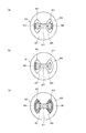
また、中間部303の内径および外径は必ずしもランプ軸X方向に沿って均一である必要はない。例えば、図14に示すように、中間部303における、放電管100の本管部102に相当する領域の内径および外径が、それ以外の領域の内径および外径よりも大きくなっているような形状、すなわち中間部303の一部に膨出部306を有する中膨形状であっても良い。膨出部306を設けることにより放電管100からの熱による外管300の温度上昇を低減することができ、外管300の材料の歪点からの裕度ができて適合する照明器具20の選択の幅を広げることができる。さらに、放電管100の破損時の安全性も向上する。その場合、膨出部306における外管300の内面304と内管200の外面204との隙間は、最大で5[mm]になるよう設計されていることが好ましい。
(Modification 5)
Further, the inner diameter and the outer diameter of the intermediate portion 303 do not necessarily have to be uniform along the lamp axis X direction. For example, as shown in FIG. 14, the inner diameter and the outer diameter of the region corresponding to the main tube portion 102 of the discharge tube 100 in the intermediate portion 303 are larger than the inner diameter and the outer diameter of the other regions. The shape may be a middle bulge shape having a bulging portion 306 in a part of the intermediate portion 303. By providing the bulging portion 306, the temperature rise of the outer tube 300 due to heat from the discharge tube 100 can be reduced, and the tolerance of the material of the outer tube 300 from the strain point can be selected, and the suitable lighting fixture 20 can be selected. Can be widened. Furthermore, the safety when the discharge tube 100 is damaged is also improved. In that case, it is preferable that the gap between the inner surface 304 of the outer tube 300 and the outer surface 204 of the inner tube 200 in the bulging portion 306 is designed to be 5 [mm] at the maximum.

(変形例6)
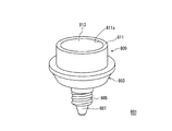
また、口金は、エジソンタイプに限定されず、図15に示すように、スワンタイプであっても良い。具体例として、スワンタイプの口金400aが、外管300の開口部301が取り付けられる本体部401aと、当該本体部401aに植設された一対の二段ピン402a,403aとを有し、第1リード線124,125の他端部が、本体部401aを貫通し、二段ピン402a,403aに挿通された状態で、かしめ部分404a,405aにおいて二段ピン402a,403aと電気的および機械的に接続されている構成とすることが考えられる。
(Modification 6)
Further, the base is not limited to the Edison type, and may be a swan type as shown in FIG. As a specific example, a swan-type base 400a includes a main body 401a to which the opening 301 of the outer tube 300 is attached, and a pair of two-stage pins 402a and 403a implanted in the main body 401a. With the other end portions of the lead wires 124 and 125 passing through the main body portion 401a and being inserted into the two-stage pins 402a and 403a, the caulking portions 404a and 405a are electrically and mechanically connected to the two-stage pins 402a and 403a. It is conceivable to have a connected configuration.

また、口金は、シェル部やアイレット部など電気的接続するために必要な部分を構成する部品、外管を保持する部分を構成する部品、内管を支持する部分を構成する部品など2つ以上の部品からなっていても、これらの部品が接着剤などにより固着されていれば良い。   In addition, there are two or more caps such as a part constituting a part necessary for electrical connection such as a shell part and an eyelet part, a part constituting a part for holding an outer pipe, and a part constituting a part for supporting an inner pipe. Even if it consists of these parts, these parts should just be fixed by the adhesive agent etc.

(変形例7)
図16は、変形例7に係る金属蒸気放電ランプを説明するための図である。図16に示すように、変形例7に係るランプの放電管710は、図3に示す放電管100のような3種類の部品を焼き嵌めたものではなく、本管部712および細管部713を一体に成形したものである。放電管710は、内部に気密封止された放電空間711を有する本管部712と、当該本管部712から放電管710の管軸(ランプの長手方向の中心軸であるランプ軸Xと一致している)方向両側に延出するように形成された細管部713,714と、からなる外囲器717を有している。なお、放電管710の外囲器717は、図3に示す放電管100のように複数の部品を焼き嵌めしたものであっても良いし、本管部712の中央部から端部にわたる半分と細管部の一方を一体に成形したものを接合して構成しても良い。
(Modification 7)
FIG. 16 is a view for explaining a metal vapor discharge lamp according to Modification 7. As shown in FIG. 16, the discharge tube 710 of the lamp according to the modified example 7 is not obtained by shrink-fitting three types of parts like the discharge tube 100 shown in FIG. 3, but includes a main tube portion 712 and a thin tube portion 713. It is molded integrally. The discharge tube 710 includes a main tube portion 712 having a discharge space 711 hermetically sealed therein, and a tube axis of the discharge tube 710 from the main tube portion 712 (a lamp axis X which is a central axis in the longitudinal direction of the lamp). And an envelope 717 composed of narrow tube portions 713 and 714 formed so as to extend on both sides in the direction. The envelope 717 of the discharge tube 710 may be one in which a plurality of parts are shrink-fitted like the discharge tube 100 shown in FIG. A structure in which one of the thin tube portions is integrally molded may be joined.

変形例7に係るランプでは、外管720の開口部721と口金730のフランジ部737とが口金730の一部である連結部材740によって連結されている。   In the lamp according to the modified example 7, the opening 721 of the outer tube 720 and the flange portion 737 of the base 730 are connected by a connecting member 740 that is a part of the base 730.

外管720は、口金側端部である開口部(ネック部)721と、口金730とは反対側の端部である閉塞部722と、それら開口部721および閉塞部722の間の中間部723とで構成される有底筒状であって、開口部721は漸次拡径している。   The outer tube 720 includes an opening (neck portion) 721 that is a base side end, a closing portion 722 that is an end opposite to the base 730, and an intermediate portion 723 between the opening 721 and the closing portion 722. The opening 721 is gradually expanded in diameter.

口金730は、筒状の本体731を有し、本体731の一端側には内管200の封止部201が挿入される筒状部分732が設けられており、本体731の他端側にはシェル733およびアイレット734が装着されている。筒状部分732のシェル733側の外周面735には、シェル733から遠い順に筒状部分732の最大外径を有するフランジ部737、及びランプ軸Xに沿った複数の溝部736が外周面735の周方向に沿って略等間隔を空けて形成されている。これにより、外周面735において、フランジ部737が最大外径、溝部736が最小外径を有する構造となる。   The base 730 has a cylindrical main body 731, a cylindrical portion 732 into which the sealing portion 201 of the inner tube 200 is inserted is provided on one end side of the main body 731, and the other end side of the main body 731 is provided on the other end side. A shell 733 and an eyelet 734 are attached. On the outer peripheral surface 735 of the cylindrical portion 732 on the shell 733 side, there are a flange portion 737 having the largest outer diameter of the cylindrical portion 732 in order of increasing distance from the shell 733, and a plurality of groove portions 736 along the lamp axis X. They are formed at substantially equal intervals along the circumferential direction. Thereby, in the outer peripheral surface 735, the flange portion 737 has a maximum outer diameter and the groove portion 736 has a minimum outer diameter.

連結部材740は、例えば金属性の筒体であって、外管720の開口部721および口金730の筒状部分732におけるフランジ部737および溝部736に跨って、それら開口部721および筒状部分732に外嵌されている。連結部材740の外管側741の内径は、外管720の開口部721の外径よりも大きく、連結部材740の口金側742の内径は、口金730の筒状部分732の外径よりも大きい。   The connecting member 740 is, for example, a metallic cylinder, and spans the opening 721 of the outer tube 720 and the flange 737 and the groove 736 in the cylindrical portion 732 of the base 730, and the opening 721 and the cylindrical portion 732. Is externally fitted. The inner diameter of the outer tube side 741 of the connecting member 740 is larger than the outer diameter of the opening 721 of the outer tube 720, and the inner diameter of the base side 742 of the connecting member 740 is larger than the outer diameter of the cylindrical portion 732 of the base 730. .

連結部材740の外管側741は、外管720の開口部721の形状に沿って縮径しており、外管720の開口部721が連結部材740内から抜け出ないようになっている。連結部材740の口金側742には、筒状部分732に設けられた溝部736に対応してかしめ部743が設けられており、このかしめ構造により連結部材740内から筒状部分732が抜け出さないようになっている。   The outer tube side 741 of the connecting member 740 is reduced in diameter along the shape of the opening 721 of the outer tube 720 so that the opening 721 of the outer tube 720 does not come out of the connecting member 740. A caulking portion 743 is provided on the base side 742 of the connecting member 740 corresponding to the groove portion 736 provided in the tubular portion 732, and the caulking structure prevents the tubular portion 732 from coming out from the inside of the connecting member 740. It has become.

以上のように、連結部材740によって、外管720と口金730とが連結されている。このような構成とすれば、口金730と異なる熱膨張率の外管720を使用することが可能になるため、ランプ設計の範囲が広がる。例えば、石英ガラス製の外管は、硬質ガラス製の外管よりも耐熱性が高いが、口金と熱膨張率が異なり過ぎるため口金に接着することは困難である。しかしながら、上記構成であれば石英ガラス製の外管を口金に連結することが可能である。   As described above, the outer tube 720 and the base 730 are connected by the connecting member 740. With such a configuration, the outer tube 720 having a coefficient of thermal expansion different from that of the base 730 can be used, so that the range of lamp design is expanded. For example, an outer tube made of quartz glass has higher heat resistance than an outer tube made of hard glass, but it is difficult to adhere to the die because the coefficient of thermal expansion is too different from that of the die. However, if it is the said structure, it is possible to connect the outer tube | pipe made from quartz glass to a nozzle | cap | die.

なお、連結部材740は、金属製に限定されないが、外管720の開口部721と口金730のフランジ部737との連結の信頼性を確保するためには、展性・塑性を有する材料で形成されていることが好ましい。展性・塑性を有する材料は放電管710破裂時の衝撃を吸収できるため、衝撃により外管720が口金730から外れ難い。また、連結部材740による外管720の開口部721と口金730のフランジ部737との連結は、上記縮径構造およびかしめ構造によるものに限定されず、係合などそれら構造以外の機械的な構造によるものであっても良い。   The connecting member 740 is not limited to metal, but is formed of a material having malleability and plasticity in order to ensure the reliability of the connection between the opening 721 of the outer tube 720 and the flange 737 of the base 730. It is preferable that Since the material having malleability and plasticity can absorb an impact when the discharge tube 710 is ruptured, the outer tube 720 is not easily detached from the base 730 due to the impact. Further, the connection between the opening 721 of the outer tube 720 and the flange 737 of the base 730 by the connecting member 740 is not limited to the above-mentioned reduced diameter structure and the caulking structure, but a mechanical structure other than these structures such as engagement. It may be due to.

(変形例8)
変形例8に係るランプとして、放電管を内部に収納する状態で一端部に封止部を有する内管が口金に接着剤により固着されていると共に、前記内管の一端から延出する一対のリード線を備え、前記内管を覆う外管の一端が前記口金に取着されてなり、前記口金は、前記封止部を囲むように配置された壁状部を有し、前記接着剤は、前記内管の一端部と前記壁状部との間に配されている共に、前記内管の一端から延出する一対のリード線の少なくとも一方から離間している構成のランプとしても良い。このような構成であれば、一対のリード線が接着剤を介して接続するようなことがなくなり、電気的不具合を未然に防ぐことができる。
(Modification 8)
As a lamp according to the modified example 8, an inner tube having a sealing portion at one end in a state in which the discharge tube is housed inside is fixed to the base with an adhesive, and a pair of members extending from one end of the inner tube. One end of an outer tube that includes a lead wire and covers the inner tube is attached to the base, and the base has a wall-like portion disposed so as to surround the sealing portion, and the adhesive is The lamp may be arranged between the one end portion of the inner tube and the wall-like portion and spaced from at least one of a pair of lead wires extending from one end of the inner tube. With such a configuration, a pair of lead wires are not connected via an adhesive, and electrical problems can be prevented in advance.

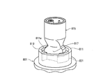
図17は、変形例8に係る口金を示す斜視図である。図17に示すように、口金801は、本体803と、本体803の他端側に装着されたシェル805およびアイレット807とにより構成されている。   FIG. 17 is a perspective view showing a base according to Modification 8. FIG. As shown in FIG. 17, the base 801 includes a main body 803 and a shell 805 and an eyelet 807 attached to the other end of the main body 803.

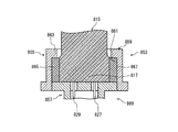
本体803の一端側には接合部809が設けられている。本体803の一端側が筒状をした筒状部分811により構成され、その筒状部分811の中央が凹入する凹入部分813となっている。図18に示すように、内管815は、凹入部分813に内管815の封止部817が挿入された状態で、凹入部分813の内部に存する接着剤819,821により封止部817と筒状部分811の内面とが結合されることで、口金801に装着される。   A joint 809 is provided on one end side of the main body 803. One end side of the main body 803 is constituted by a cylindrical portion 811 having a cylindrical shape, and a central portion of the cylindrical portion 811 is a recessed portion 813 into which it is recessed. As shown in FIG. 18, the inner tube 815 includes the sealing portion 817 by the adhesives 819 and 821 existing inside the recessed portion 813 in a state where the sealing portion 817 of the inner tube 815 is inserted into the recessed portion 813. And the inner surface of the cylindrical portion 811 are connected to the base 801.

筒状部分811は、封止部817を囲むように本体803に設けられており、本発明の「壁状部」に相当する。また、内管815(外管823であっても同じである。)の管軸方向から口金801の筒状部分811を見たときに、筒状部分811の外周面が外管823の一端側の端部の内周面に沿った形状をしている。   The cylindrical portion 811 is provided in the main body 803 so as to surround the sealing portion 817, and corresponds to the “wall-shaped portion” of the present invention. Further, when the cylindrical portion 811 of the base 801 is viewed from the tube axis direction of the inner tube 815 (the same applies to the outer tube 823), the outer peripheral surface of the cylindrical portion 811 is one end side of the outer tube 823. It has a shape along the inner peripheral surface of the end portion.

図19に示すように、外管823は、接合部809の筒状部分811を套設した状態、つまり、外管823の一端部内に筒状部分811を挿入した状態で、接着剤825により口金801に固着されている。外管823は、一端端部の横断面形状が例えば円環状をし、口金801の筒状部分811は、その横断面形状が円環状をし、筒状部分811の周壁が全周に亘って外管823の内周面に対向する状態で、筒状部分811が外管823に内嵌している。   As shown in FIG. 19, the outer tube 823 is formed by the adhesive 825 with the tubular portion 811 of the joint portion 809 being installed, that is, with the tubular portion 811 inserted into one end of the outer tube 823. It is fixed to 801. The outer tube 823 has, for example, an annular cross section at one end, and the cylindrical portion 811 of the base 801 has an annular cross section, and the peripheral wall of the cylindrical portion 811 extends over the entire circumference. The cylindrical portion 811 is fitted into the outer tube 823 in a state of facing the inner peripheral surface of the outer tube 823.

内管815の封止部817は、内管815の一端部を加熱させて、ピンチ(ピンチシールするため道具)により圧潰することで形成される(このため、「圧潰封止」とも呼ばれる。)。従って、図19に示すように、ピンチにより押圧時にピンチに接触している部分(の外面)は平坦面817a,817bとなり、ピンチに接触していない部分(の外面)は、ピンチの間から押圧方向と直交する方向に膨出して膨出面817c,817dとなる。   The sealing portion 817 of the inner tube 815 is formed by heating one end portion of the inner tube 815 and crushing it with a pinch (tool for pinch sealing) (for this reason, it is also referred to as “crush sealing”). . Accordingly, as shown in FIG. 19, the portions (outer surfaces) that are in contact with the pinch when pressed by the pinch are flat surfaces 817a and 817b, and the portions that are not in contact with the pinch (outer surface) are pressed from between the pinches. It bulges in a direction orthogonal to the direction to form bulged surfaces 817c and 817d.

凹入部分813内の接着剤819,821は、封止部817の膨出面817c,817dと筒状部分811の内面(811a)との間であって別々に離れた状態で配され、両者を固着している。また、接着剤819,821は、凹入部分813から張り出さずに凹入部分813内に存している。このため、ランプの外観において凹入部分813内の接着剤819,821が見え難く、外観上の意匠性を損なうようなことを少なくできる。   The adhesives 819 and 821 in the recessed portion 813 are arranged between the bulging surfaces 817c and 817d of the sealing portion 817 and the inner surface (811a) of the cylindrical portion 811 and are separated from each other. It is stuck. Further, the adhesives 819 and 821 are present in the recessed portion 813 without protruding from the recessed portion 813. For this reason, it is difficult to see the adhesives 819 and 821 in the recessed portion 813 in the appearance of the lamp, and it is possible to reduce the possibility of impairing the appearance design.

内管815を口金801に装着する内管装着工程では、まず、筒状部分811の開口が上方を向くように口金801を配置する。次に、筒状部分811内に内管815の封止部817を挿入させる。このとき、筒状部分811の底部分に設けられた一対の貫通孔に、内管815の一端部から延出している一対のリード線827,829を通す。   In the inner tube mounting step of mounting the inner tube 815 on the base 801, first, the base 801 is disposed so that the opening of the cylindrical portion 811 faces upward. Next, the sealing portion 817 of the inner tube 815 is inserted into the cylindrical portion 811. At this time, a pair of lead wires 827 and 829 extending from one end of the inner tube 815 are passed through a pair of through holes provided in the bottom portion of the cylindrical portion 811.

そして、内管815の姿勢を正し、口金801に対する内管815の位置決めを行った後、封止部817の膨出面817c,817dと、筒状部分811の内周面811aであって膨出面817c,817dと対向する面(811a)との間に接着剤819,821を独立した島状態で注入し、内管815と口金801とを固着する。   Then, after the posture of the inner tube 815 is corrected and the inner tube 815 is positioned with respect to the base 801, the swollen surfaces 817c and 817d of the sealing portion 817 and the inner peripheral surface 811a of the cylindrical portion 811 are swollen. Adhesives 819 and 821 are injected in an independent island state between 817c and 817d and the face (811a) facing each other, and the inner tube 815 and the base 801 are fixed.

この際、接着剤819,821は、平面視において、一対のリード線827,829を結ぶ直線上に独立して位置しているので、各接着剤819,821が封止部817以外の部位にフローしても、一対のリード線827,829を結合接触することはなく、接着剤819,821が水分を吸着して生じる電気的短絡を予防することができる。好ましくは、接着剤819,821がリード線827,829の間にフローされないようにすることで、異極間の絶縁距離を適正に保つことができる。   At this time, since the adhesives 819 and 821 are independently positioned on a straight line connecting the pair of lead wires 827 and 829 in a plan view, the adhesives 819 and 821 are placed on portions other than the sealing portion 817. Even if the flow is performed, the pair of lead wires 827 and 829 are not brought into contact with each other, and an electrical short circuit caused by the adhesive 819 and 821 adsorbing moisture can be prevented. Preferably, by preventing the adhesives 819 and 821 from flowing between the lead wires 827 and 829, the insulation distance between the different poles can be kept appropriate.

内管815と口金801とが固着されると、外管823の一端部の内周面および口金801の筒状部分811の外周面に接着剤825(あるいは、外管823の一端部の内周面および口金801の筒状部分811の外周面の何れか一方の面でも良い)を塗布し、外管823の一端部を口金801の筒状部分811に被覆して、両者を固着する。   When the inner tube 815 and the base 801 are fixed, the adhesive 825 (or the inner periphery of one end of the outer tube 823) is attached to the inner peripheral surface of one end of the outer tube 823 and the outer peripheral surface of the cylindrical portion 811 of the base 801. The surface and the outer peripheral surface of the cylindrical portion 811 of the base 801 may be applied), and one end portion of the outer tube 823 is covered with the cylindrical portion 811 of the base 801 to fix them together.

上記説明したランプの構成では、外管823が口金801に固着されているため、照明器具に装着する際に、使用者は、ランプの外管823を持って、照明器具のソケットにねじ込むため、内管815には装着時の負荷が作用することはない。このため、内管815と口金801との結合力は、内管815と口金801との位置関係が保持できる程度であれば良く、内管815と口金801とを固着する接着剤819,821の使用量を少なくできる。   In the configuration of the lamp described above, the outer tube 823 is fixed to the base 801. Therefore, when the user mounts the lamp on the lighting fixture, the user holds the lamp outer tube 823 and screws it into the socket of the lighting fixture. The inner pipe 815 is not subjected to a load during mounting. For this reason, the bonding force between the inner tube 815 and the base 801 is sufficient if the positional relationship between the inner tube 815 and the base 801 can be maintained, and the adhesives 819 and 821 for fixing the inner tube 815 and the base 801 to each other. The amount used can be reduced.

(変形例9)
変形例8に係る口金801の凹入部分813は平面視において円形状をしていたが、凹入部分の平面形状は他の形状であっても良い。以下、平面視形状が円形状以外の凹入部分の一例を説明する。
(Modification 9)
The recessed portion 813 of the base 801 according to the modified example 8 has a circular shape in plan view, but the planar shape of the recessed portion may be another shape. Hereinafter, an example of a recessed portion whose planar view shape is other than a circular shape will be described.

図20は、変形例9に係る口金を示す斜視図であり、口金部は省略している。図20に示すように、口金831の接合部833は筒状部分835により構成され、筒状部分835の内周面837の一部が、筒状部分835の中心軸側に張り出している。つまり、筒状部分835がその中心軸側に張り出す張り出し領域839,841を有している。   FIG. 20 is a perspective view showing a base according to Modification Example 9, and the base part is omitted. As shown in FIG. 20, the joint portion 833 of the base 831 is configured by a cylindrical portion 835, and a part of the inner peripheral surface 837 of the cylindrical portion 835 projects to the central axis side of the cylindrical portion 835. That is, the tubular portion 835 has overhanging regions 839 and 841 that project toward the center axis.

張り出し領域839,841は、内管815の封止部817が挿入された際に、封止部817の平坦面817a,817bに当接する。なお、封止部817の厚み(一対のリード線827,829を結ぶ仮想線と直交する方向の厚みである。)は、封止時の一対のピンチ間の距離を管理することにより略一定とすることができ、この距離にあわせて、張り出し領域839,841の張り出し量を決定できる。   The overhang regions 839 and 841 come into contact with the flat surfaces 817a and 817b of the sealing portion 817 when the sealing portion 817 of the inner tube 815 is inserted. Note that the thickness of the sealing portion 817 (the thickness in the direction perpendicular to the virtual line connecting the pair of lead wires 827 and 829) is substantially constant by managing the distance between the pair of pinches at the time of sealing. The amount of overhang of the overhang regions 839 and 841 can be determined according to this distance.

図21は、変形例9に係る内管と口金との接合部分を示す断面図である。図21(a),(b),(c)には、いずれも封止部817において管軸に垂直な平面におけるリード線827,829を結ぶ仮想線の延伸する方向(以下、「仮想線方向」ともいう。)であって封止部817の外側の2つの領域の少なくともいずれかに接着剤が配されていることが示されている。つまり、リード線827,829を結ぶ仮想線方向であって封止部817と口金831の筒状部分835との間に形成される2つのスペースのうち、少なくともいずれかのスペースに接着剤が配されている。   FIG. 21 is a cross-sectional view showing a joint portion between an inner tube and a base according to Modification 9. 21 (a), (b), and (c) all show the direction in which the imaginary line connecting the lead wires 827 and 829 in the plane perpendicular to the tube axis extends (hereinafter referred to as “virtual line direction”). It is also shown that the adhesive is disposed in at least one of the two regions outside the sealing portion 817. In other words, the adhesive is disposed in at least one of the two spaces formed between the sealing portion 817 and the cylindrical portion 835 of the base 831 in the imaginary line direction connecting the lead wires 827 and 829. Has been.

図21(a)では、口金831と内管815とを固着する接着剤843,845は、変形例8と同様に、封止部817の膨出面817c,817dと、筒状部分835の内周面837であって膨出面817c,817dと対向する面(837)との間に配されている。なお、本例の場合も、接着剤843,845は、平面視において、一対のリード線827,829を結ぶ仮想直線上に位置している。   In FIG. 21A, the adhesives 843 and 845 for fixing the base 831 and the inner tube 815 are the bulging surfaces 817c and 817d of the sealing portion 817 and the inner periphery of the cylindrical portion 835, as in the modification 8. The surface 837 is disposed between the bulging surfaces 817c and 817d and a surface (837) facing the surface 837. Also in this example, the adhesives 843 and 845 are located on an imaginary straight line connecting the pair of lead wires 827 and 829 in plan view.

図21(a)では、接着剤843,845は、互いに独立した状態で2箇所に配されていたが、図21(b)では、接着剤が一箇所に設けられている。つまり、接着剤847は、封止部817の膨出面817c,817dと、筒状部分835の内周面837であって膨出面817c,817dと対向する面(837)との間の一方だけ配されている。なお、本例の場合も、接着剤847は、一対のリード線827,829を結ぶ仮想線上に位置しているが、接着剤(847)は、仮想線上に位置していなくても良い。   In FIG. 21A, the adhesives 843 and 845 are disposed at two locations in an independent state, but in FIG. 21B, the adhesive is provided at one location. That is, the adhesive 847 is disposed only on one side between the bulging surfaces 817c and 817d of the sealing portion 817 and the inner peripheral surface 837 of the cylindrical portion 835 that faces the bulging surfaces 817c and 817d (837). Has been. Also in this example, the adhesive 847 is located on the imaginary line connecting the pair of lead wires 827 and 829, but the adhesive (847) may not be located on the imaginary line.

図21(a)では、筒状部分835の凹入部分に空間を残して接着剤843,845が配されていたが、図21(c)では、凹入部分と封止部817との間の隙間がすべて埋まるように接着剤849,851が充填されている。この場合でも、接着剤251はリード線829と離れ、接着剤253はリード線827と離れている。このため、接着剤849,851はフローしても、一対のリード線827,829の両方に接触するようなことは生じ難い。   In FIG. 21A, the adhesives 843 and 845 are disposed leaving a space in the recessed portion of the cylindrical portion 835, but in FIG. 21C, between the recessed portion and the sealing portion 817. Adhesives 849 and 851 are filled so that all the gaps are filled. Even in this case, the adhesive 251 is separated from the lead wire 829, and the adhesive 253 is separated from the lead wire 827. For this reason, even if the adhesives 849 and 851 flow, it is unlikely to come into contact with both the pair of lead wires 827 and 829.

このように、仮想線方向において、リード線827を含みリード線829と離間する封止部817の一方の側部(封止部817の外周部の一部である。)と、リード線829を含みリード線827と離間する封止部817の他方の側部(封止部817の外周部の前記一部と異なる他部である。)の少なくともいずれかに接着剤が配されることにより、接着剤間の距離を大きくできるため、安全性を高めることができる。   As described above, in the imaginary line direction, one side portion of the sealing portion 817 including the lead wire 827 and separated from the lead wire 829 (a part of the outer peripheral portion of the sealing portion 817) and the lead wire 829 are arranged. By disposing an adhesive on at least one of the other side portions of the sealing portion 817 spaced apart from the including lead wire 827 (the other portion different from the portion of the outer peripheral portion of the sealing portion 817), Since the distance between the adhesives can be increased, safety can be improved.

なお、変形例8および変形例9の説明では、接着剤は封止部817の一対のリード線827,829を結ぶ仮想線方向に配設されていたが、仮想線方向において、リード線827を含みリード線829と離間する封止部817の一方の平坦面(例えば、図19の「817a」である。)と、リード線829を含みリード線827と離間する封止部817の他方の平坦面(例えば、図19の「817b」である。)の少なくともいずれかを含むスぺ−スに接着剤を配しても良い。   In the description of the modification examples 8 and 9, the adhesive is disposed in the imaginary line direction connecting the pair of lead wires 827 and 829 of the sealing portion 817. One flat surface (for example, “817a” in FIG. 19) of the sealing portion 817 spaced apart from the lead wire 829 and the other flat surface of the sealing portion 817 remote from the lead wire 827 including the lead wire 829. An adhesive may be disposed on a space including at least one of the surfaces (for example, “817b” in FIG. 19).

(変形例10)
変形例8および変形例9では、口金801,831は、接合部809,833を有する本体(803)にシェル(805)とアイレット(807)が装着されていたが、例えば、口金部を有する部材と、シェルとアイレットが装着される部材とが別体であっても良い。この場合を、変形例10として説明する。
(Modification 10)
In the modified examples 8 and 9, the bases 801 and 831 have the shell (805) and the eyelet (807) attached to the main body (803) having the joint portions 809 and 833. In addition, the shell and the member to which the eyelet is attached may be separate. This case will be described as a tenth modification.

図22は、変形例10に係る内管と口金との接合部分を示す断面図である。なお、図22は、内管815が装着された状態であって、口金853だけを切り欠いた図である。   FIG. 22 is a cross-sectional view illustrating a joint portion between the inner tube and the base according to the tenth modification. FIG. 22 is a view in which only the base 853 is cut out with the inner tube 815 attached.

図22に示すように、変形例10に係る口金853は、筒体855と蓋体857とを備える。筒体855は、内部の開口(凹入部分)に挿入された内管815(封止部817)と接合する接合部859を構成する。筒体855の内面861には、開口側端部に内側に張り出す張出部分863が設けられている。また、封止部817と筒体855との隙間の2箇所には接着剤865,867が配されている。これにより、筒体855と内管815とが固着される。   As shown in FIG. 22, the base 853 according to Modification 10 includes a cylinder 855 and a lid 857. The cylindrical body 855 constitutes a joint portion 859 that joins the inner tube 815 (sealing portion 817) inserted into the internal opening (recessed portion). On the inner surface 861 of the cylindrical body 855, an overhanging portion 863 that protrudes inward is provided at the opening side end. Adhesives 865 and 867 are disposed at two locations in the gap between the sealing portion 817 and the cylinder 855. Thereby, the cylinder 855 and the inner tube 815 are fixed.

なお、変形例10では、内管815は口金853に接着剤865,867で固着されていたが、内管815と口金853とが互いの動きを規制することができる部材、例えば、内管815と口金853との間の隙間を充填する充填部材であっても良い。   In the modified example 10, the inner tube 815 is fixed to the base 853 with adhesives 865 and 867. However, the inner tube 815 and the base 853 are members that can restrict the movement of each other, for example, the inner tube 815. It may be a filling member that fills the gap between the base 853 and the base 853.

この充填部材は、変形例8等と同様に、一対のリード線827,829を結ぶ仮想線上に配されても良いし、他の箇所に配されても良い。但し、この充填部材は、内管815と口金853との間の隙間から外れないようにする必要があり、例えば、上記張出部分863を設け、当該張出部分863と充填部材とを当接させるようにしても良い。   This filling member may be arranged on an imaginary line connecting the pair of lead wires 827 and 829 as in the modified example 8 or the like, or may be arranged in another location. However, it is necessary for this filling member not to be removed from the gap between the inner tube 815 and the base 853. For example, the overhang portion 863 is provided, and the overhang portion 863 and the filling member are brought into contact with each other. You may make it let it.

口金部869は、蓋体857と、蓋体857に装着されたシェルおよびアイレット(図示省略)により構成されている。なお、蓋体857と筒体855との接合は、例えば、接着剤により行われている。   The base portion 869 includes a lid body 857, a shell and an eyelet (not shown) attached to the lid body 857. Note that the lid 857 and the cylinder 855 are joined by, for example, an adhesive.

(変形例11)
図23は、変形例11に係る内管と口金との接合部分を示す断面図である。なお、図23は、図22と同様に、内管815が装着された状態であって、口金871だけを切り欠いた図である。
(Modification 11)
FIG. 23 is a cross-sectional view showing a joint portion between the inner tube and the base according to the eleventh modification. FIG. 23 is a view in which only the base 871 is cut out in a state in which the inner tube 815 is mounted, as in FIG.

図23に示すように、変形例11に係る口金871は、接合部873と口金部875とを備える。なお、口金部875は、変形例8等と同じであり、ここでの説明は省略する。   As illustrated in FIG. 23, the base 871 according to Modification 11 includes a joint portion 873 and a base portion 875. The base portion 875 is the same as that of the modified example 8 and the like, and the description thereof is omitted here.

接合部873は、筒状部分877を有し、本体部879の底、つまり、筒状部分877の内側の凹入部分の底の中央が筒状部分877の開口側へと隆起する隆起領域881を有する。なお、内管815の一端から延出するリード線827,829用の貫通孔が設けられている。   The joint portion 873 has a tubular portion 877, and a raised region 881 in which the bottom of the main body portion 879, that is, the center of the bottom of the recessed portion inside the tubular portion 877 bulges toward the opening side of the tubular portion 877. Have Note that through holes for lead wires 827 and 829 extending from one end of the inner tube 815 are provided.

内管815の接合部873への接合は、内管815の一端が凹入部分の隆起領域881の当接する状態で、封止部と筒状部分877の内面とが接着剤883,885により固着されている。このように凹入部分の底に隆起領域881を有しているため、凹入部分内の接着剤883,885がフローし難くなり、接着剤883,885とリード線827,829とが接触するようなことをなくすことができる。   The inner tube 815 is bonded to the bonding portion 873 in a state where one end of the inner tube 815 is in contact with the raised region 881 of the recessed portion, and the sealing portion and the inner surface of the cylindrical portion 877 are fixed by the adhesives 883 and 885. Has been. Since the raised region 881 is provided at the bottom of the recessed portion as described above, the adhesives 883 and 885 in the recessed portion are difficult to flow, and the adhesives 883 and 885 are in contact with the lead wires 827 and 829. Such things can be eliminated.

本発明は、放電管、内管および外管を備えた三重管構造の金属蒸気放電ランプに利用できる。   The present invention can be used for a metal vapor discharge lamp having a triple tube structure including a discharge tube, an inner tube, and an outer tube.

1 照明装置
10 金属蒸気放電ランプ
100,710 放電管
200,815 内管
202 先端部
204 外面
300,720 外管
301,721 開口部
302,722 閉塞部
304 内面
400,730 口金
DESCRIPTION OF SYMBOLS 1 Illuminating device 10 Metal vapor discharge lamp 100,710 Discharge tube 200,815 Inner tube 202 Tip part 204 Outer surface 300,720 Outer tube 301,721 Opening part 302,722 Closure part 304 Inner surface 400,730 Base

Claims (8)

一端に開口部を有し他端に閉塞部を有する外管と、当該外管内に収納され内部に放電管が配置された内管と、前記外管の開口部に取り付けられた口金とを備え、
前記外管の閉塞部の最薄肉厚をt[mm]とし、前記外管の閉塞部の内面と、前記内管の前記口金とは反対側の端部の外面との前記外管管軸方向における最短距離をd[mm]とした場合に、t≧1.1×d−0.4、且つ、0<d、且つ、0.3≦t、の関係を満たすことを特徴とする金属蒸気放電ランプ。
An outer tube having an opening at one end and a closing portion at the other end, an inner tube housed in the outer tube and having a discharge tube disposed therein, and a base attached to the opening of the outer tube ,
The thinnest wall thickness of the closed portion of the outer tube is t [mm], and the outer tube axis direction of the inner surface of the closed portion of the outer tube and the outer surface of the end portion of the inner tube opposite to the base Metal vapor characterized by satisfying the relationship of t ≧ 1.1 × d −0.4 and 0 <d and 0.3 ≦ t where d is the shortest distance in Discharge lamp.
前記内管の口金とは反対側の端部の形状が略半球状である請求項1記載の金属蒸気放電ランプ。  The metal vapor discharge lamp according to claim 1, wherein the shape of the end of the inner tube opposite to the cap is substantially hemispherical. 前記外管の閉塞部の内面は、曲率半径R[mm]が8.0以上の曲面、または、略平面であることを特徴とする請求項1または2に記載の金属蒸気放電ランプ。  3. The metal vapor discharge lamp according to claim 1, wherein an inner surface of the closed portion of the outer tube is a curved surface having a curvature radius R [mm] of 8.0 or more or a substantially flat surface. 消費電力が30[W]〜80[W]であることを特徴とする請求項1から3のいずれかに記載の金属蒸気放電ランプ。  The metal vapor discharge lamp according to any one of claims 1 to 3, wherein power consumption is 30 [W] to 80 [W]. 前記最短距離dが15[mm]以下であることを特徴とする請求項1から4のいずれかに記載の金属蒸気放電ランプ。  The metal vapor discharge lamp according to any one of claims 1 to 4, wherein the shortest distance d is 15 mm or less. 前記最薄肉厚tが1.1[mm]以上3.0[mm]以下であることを特徴とする請求項1から5のいずれかに記載の金属蒸気放電ランプ。  6. The metal vapor discharge lamp according to claim 1, wherein the thinnest thickness t is 1.1 [mm] or more and 3.0 [mm] or less. 前記外管が、硬質ガラス、石英ガラスまたはアルミナセラミックのいずれかで構成されていることを特徴とする請求項1から6のいずれかに記載の金属蒸気放電ランプ。  7. The metal vapor discharge lamp according to claim 1, wherein the outer tube is made of any one of hard glass, quartz glass, and alumina ceramic. 請求項1から7のいずれかに記載の金属蒸気放電ランプと、当該金属蒸気放電ランプから発せられた光を所望の方向に反射させる反射鏡とを備えることを特徴とする照明装置。  An illuminating device comprising: the metal vapor discharge lamp according to any one of claims 1 to 7; and a reflecting mirror that reflects light emitted from the metal vapor discharge lamp in a desired direction.
JP2011529095A 2010-08-06 2011-05-02 Metal vapor discharge lamp and lighting device Expired - Fee Related JP5082012B2 (en)

Priority Applications (1)

Application Number Priority Date Filing Date Title
JP2011529095A JP5082012B2 (en) 2010-08-06 2011-05-02 Metal vapor discharge lamp and lighting device

Applications Claiming Priority (4)

Application Number Priority Date Filing Date Title
JP2010177699 2010-08-06
JP2011529095A JP5082012B2 (en) 2010-08-06 2011-05-02 Metal vapor discharge lamp and lighting device
PCT/JP2011/002537 WO2012017581A1 (en) 2010-08-06 2011-05-02 Metal-vapor discharge lamp and illumination apparatus

Publications (2)

Publication Number Publication Date
JP5082012B2 true JP5082012B2 (en) 2012-11-28
JPWO2012017581A1 JPWO2012017581A1 (en) 2013-09-19

Family

ID=45559107

Family Applications (1)

Application Number Title Priority Date Filing Date
JP2011529095A Expired - Fee Related JP5082012B2 (en) 2010-08-06 2011-05-02 Metal vapor discharge lamp and lighting device

Country Status (6)

Country Link
US (1) US8519605B2 (en)
EP (1) EP2479778A4 (en)
JP (1) JP5082012B2 (en)
KR (1) KR20130102453A (en)
CN (1) CN102484036A (en)
WO (1) WO2012017581A1 (en)

Families Citing this family (1)

* Cited by examiner, † Cited by third party
Publication number Priority date Publication date Assignee Title
EP2847778A1 (en) * 2012-05-07 2015-03-18 Koninklijke Philips N.V. Electric lamp and assembling method therefore

Citations (3)

* Cited by examiner, † Cited by third party
Publication number Priority date Publication date Assignee Title
JP2007522606A (en) * 2003-08-07 2007-08-09 パテント−トロイハント−ゲゼルシヤフト フユール エレクトリツシエ グリユーラムペン ミツト ベシユレンクテル ハフツング Single-sided mold lamp
JP2009289524A (en) * 2008-05-28 2009-12-10 Panasonic Corp Lamp and lighting system using the same
JP2010056031A (en) * 2008-08-29 2010-03-11 Osram Melco Toshiba Lighting Kk High-pressure discharge lamp and lighting device

Family Cites Families (4)

* Cited by examiner, † Cited by third party
Publication number Priority date Publication date Assignee Title
EP1763066B1 (en) * 2004-06-29 2010-10-06 Panasonic Corporation Metal halide lamp and lighting apparatus using the same
WO2006047438A2 (en) 2004-10-22 2006-05-04 Bayer Cropscience Ag Insecticidal 3-(dihaloalkenyl) phenyl derivatives
KR101121392B1 (en) 2006-05-31 2012-04-12 파나소닉 주식회사 Metal vapor discharge lamp and illumination apparatus
JP4130842B2 (en) * 2006-05-31 2008-08-06 松下電器産業株式会社 Metal vapor discharge lamp and lighting device

Patent Citations (3)

* Cited by examiner, † Cited by third party
Publication number Priority date Publication date Assignee Title
JP2007522606A (en) * 2003-08-07 2007-08-09 パテント−トロイハント−ゲゼルシヤフト フユール エレクトリツシエ グリユーラムペン ミツト ベシユレンクテル ハフツング Single-sided mold lamp
JP2009289524A (en) * 2008-05-28 2009-12-10 Panasonic Corp Lamp and lighting system using the same
JP2010056031A (en) * 2008-08-29 2010-03-11 Osram Melco Toshiba Lighting Kk High-pressure discharge lamp and lighting device

Also Published As

Publication number Publication date
US20120267994A1 (en) 2012-10-25
CN102484036A (en) 2012-05-30
JPWO2012017581A1 (en) 2013-09-19
KR20130102453A (en) 2013-09-17
EP2479778A1 (en) 2012-07-25
WO2012017581A1 (en) 2012-02-09
US8519605B2 (en) 2013-08-27
EP2479778A4 (en) 2012-10-03

Similar Documents

Publication Publication Date Title
US7652429B2 (en) Electrodes with cermets for ceramic metal halide lamps
JP4130842B2 (en) Metal vapor discharge lamp and lighting device
US7615929B2 (en) Ceramic lamps and methods of making same
JP5082012B2 (en) Metal vapor discharge lamp and lighting device
JP4922078B2 (en) Metal halide lamp
JP4846856B2 (en) High intensity discharge lamp
US8558457B2 (en) Lamp comprising glass tube having pinched sealed portion at end
JP2005317504A (en) Lamp having inside lamp/stem assembly, and its manufacturing method
JP5134054B2 (en) Metal vapor discharge lamp and lighting device
JP2012043588A (en) Metal vapor discharge lamp and luminaire
JP3576159B2 (en) High pressure discharge lamp
JP5799437B2 (en) High intensity discharge lamp with outer bulb protection structure
JP2007294130A (en) Self-ballasted fluorescent lamp and lighting fixture
JPWO2005088674A1 (en) Metal vapor discharge lamp, manufacturing method thereof, and lamp with reflector
JP2013004434A (en) High-pressure discharge lamp and luminaire
JP2020024893A (en) Encapsulation structure for discharge lamp and discharge lamp with the same
JP2012230849A (en) High-pressure discharge lamp and illuminating device
JP2011249292A (en) High-pressure metal vapor discharge lamp and lighting apparatus
JP2000021352A (en) One-sided base discharge lamp, shield beam device using it, and shield beam lighting device
JP2012048879A (en) Metal vapor discharge lamp
JP2012048878A (en) Metal vapor discharge lamp
JPH07230789A (en) Bulb, light source and lighting system
JP2010251263A (en) Fluorescent lamp
JP2010238511A (en) Fluorescent lamp, and planar light source device

Legal Events

Date Code Title Description
TRDD Decision of grant or rejection written
A01 Written decision to grant a patent or to grant a registration (utility model)

Free format text: JAPANESE INTERMEDIATE CODE: A01

Effective date: 20120828

A01 Written decision to grant a patent or to grant a registration (utility model)

Free format text: JAPANESE INTERMEDIATE CODE: A01

A61 First payment of annual fees (during grant procedure)

Free format text: JAPANESE INTERMEDIATE CODE: A61

Effective date: 20120903

FPAY Renewal fee payment (event date is renewal date of database)

Free format text: PAYMENT UNTIL: 20150907

Year of fee payment: 3

R150 Certificate of patent or registration of utility model

Free format text: JAPANESE INTERMEDIATE CODE: R150

LAPS Cancellation because of no payment of annual fees