JP4589084B2 - A retaining wall with a built-in water pipe composed of a plurality of water passages, and a method for ensuring the flow of groundwater using the retaining wall - Google Patents
A retaining wall with a built-in water pipe composed of a plurality of water passages, and a method for ensuring the flow of groundwater using the retaining wall Download PDFInfo
- Publication number
- JP4589084B2 JP4589084B2 JP2004329674A JP2004329674A JP4589084B2 JP 4589084 B2 JP4589084 B2 JP 4589084B2 JP 2004329674 A JP2004329674 A JP 2004329674A JP 2004329674 A JP2004329674 A JP 2004329674A JP 4589084 B2 JP4589084 B2 JP 4589084B2
- Authority
- JP
- Japan
- Prior art keywords
- water
- retaining wall
- passage
- water passage
- flow
- Prior art date
- Legal status (The legal status is an assumption and is not a legal conclusion. Google has not performed a legal analysis and makes no representation as to the accuracy of the status listed.)
- Active
Links
Images


Description
本発明は、複数の通水路からなる通水筒を内蔵した土留壁及び地盤開削の前後において該土留壁を用いた地下水の流動確保方法に関するものである。
The present invention relates to a retaining wall with a built-in water pipe formed of a plurality of water passages, and a method for securing the flow of groundwater using the retaining wall before and after ground excavation .
従来より、SMW壁等の遮水性土留壁に通水機能を付加する方法においては、以下の方法等が挙げられる。
<1>未固化のソイルセメントに注水チューブを挿入し、同チューブを拡張し、ソイルセメントを押し出すことで通水空間を確保する方法。
<2>未固化のソイルセメントにフィルター材を装着した2つ割構造のスクリーンを挿入し、拡張ジャッキでスクリーンを地山に押し付け通水空間を確保する方法。
<3>ソイルセメント壁硬化後、ソイルセメントを削孔し、通水空間を確保する方法。
<4>未固化のソイルセメントにピストン(円管の先に鋼製のカバーを取り付けた部材)を配置した通水装置付特殊芯材を建て込み、ソイルセメント硬化後にピストンを背面地山に挿入しピストン先端の鋼製カバーを電食にて溶解し通水機能を発揮する方法。
Conventionally, methods for adding a water flow function to a water-impervious earth retaining wall such as an SMW wall include the following methods.
<1> A method of securing a water flow space by inserting a water injection tube into unsolidified soil cement, expanding the tube, and extruding the soil cement.
<2> A method of inserting a split screen with filter material into unsolidified soil cement and pressing the screen against a natural ground with an expansion jack to secure a water passage space.
<3> A method of drilling the soil cement to secure a water passage space after the soil cement wall is hardened.
<4> A special core material with a water flow device with a piston (a member with a steel cover attached to the end of a circular pipe) is built in unsolidified soil cement, and the piston is inserted into the back ground after hardening the soil cement The steel cover at the tip of the piston is melted by electrolytic corrosion to achieve the water flow function.
しかし、前記した従来の通水機能の付加方法にあっては、以下のような問題点がある。
<1>通水部のソイルセメントを完全に除去することは困難であり、またソイルセメントの押し出し状況によっては十分なフィルター材の投入空間を確保できないこともあることから、通水機能の低下が問題となるおそれがある。さらに、土留壁構築に長時間を要する大規模開削工事では、土留壁構築時の地下水流動保全を目的に別途対策を講じる必要がある。
<2>通水部のソイルセメントを完全に除去することは困難であり、通水機能の低下が問題となる恐れがある。また芯材は特殊な形状であることから、ソイルセメントの造成深度および造成状況によっては芯材が建て込み困難となる恐れがある。
<3>SMW壁の背面に通水構築用地が必要となる。また、ソイルセメントの削孔に当たっては全周回転開削機等の建設重機が別途必要となり、工期及び工費の面で負担が大きくなる。更に、土留壁構築に長期間を要する大規模開削工事では、土留壁構築時の地下水流動保全を目的に別途対策を講じる必要がある。
<4>通水能力は、ピストンの挿入状況に依存するため信頼性が低い。また、ピストンの背面地山の間にある硬化したソイルセメントは除去できないため、通水機能の低下が問題となる恐れがある。さらに、土留壁構築に長期間を要する大規模開削工事では、土留壁の構築時の地下水流動保全を目的に別途対策を講じる必要がある。
However, the conventional method for adding a water flow function has the following problems.
<1> It is difficult to completely remove the soil cement in the water flow section, and depending on the extrusion condition of the soil cement, it may not be possible to secure a sufficient input space for the filter material. May be a problem. Furthermore, in large-scale excavation work that requires a long time to construct the retaining wall, it is necessary to take separate measures for the purpose of maintaining the groundwater flow when constructing the retaining wall.
<2> It is difficult to completely remove the soil cement in the water passage portion, and there is a possibility that the deterioration of the water passage function becomes a problem. In addition, since the core material has a special shape, it may be difficult to install the core material depending on the depth and condition of the soil cement.
<3> A water passage construction site is required on the back of the SMW wall. In addition, a heavy construction machine such as an all-round rotary excavator is required for drilling the soil cement, which increases the burden in terms of construction period and construction cost. Furthermore, in large-scale excavation work that requires a long period of time for the construction of the retaining wall, it is necessary to take separate measures for the purpose of maintaining the groundwater flow during the construction of the retaining wall.
<4> The water flow capacity is low in reliability because it depends on the piston insertion situation. Moreover, since the hardened soil cement between the back ground of a piston cannot be removed, there exists a possibility that the fall of a water flow function may become a problem. Furthermore, in large-scale excavation work that requires a long period of time to construct the retaining wall, it is necessary to take separate measures for the purpose of groundwater flow conservation when constructing the retaining wall.
上記のような課題を解決するために、本願の第1発明は、止水壁間に設けて、該止水壁により仕切られた地盤間の水の流動を制御するための通水土留壁であって、地中に掘削した通水縦坑と、前記縦坑の内部に設置した、互いに並行する複数の通水路からなる通水筒と、通水縦坑と通水筒との間に充填した通水材と、前記通水筒の側部に設けて、前記止水壁と接続する止水継手とより構成し、前記通水筒は、互いに隣接して設けた外側通水路と内側通水路とにより構成し、外側通水路は、止水壁で仕切られた土留壁背面側に外側開口部を備え、内側通水路は、開削側に開口した切り欠き部と、隣接する外側通水路との間の側壁部分に開口した内側開口部と、切欠き部と内側開口部との間に位置する止水栓装着部とを備え、内側通水路の止水栓装着部に止水栓を装着して、内側通水路の内側開口部と、切欠き部との間を遮水し得るように構成した、通水土留壁を提供するものである。 In order to solve the above-described problems, the first invention of the present application is a water retaining wall for controlling water flow between grounds provided between water blocking walls and partitioned by the water blocking walls. A water drainage shaft excavated in the ground, a water pipe composed of a plurality of parallel water passages installed inside the vertical shaft, and a channel filled between the water flow vertical shaft and the water pipe. A water material and a water stop joint provided on a side portion of the water pipe and connected to the water stop wall are configured, and the water pipe is configured by an outer water flow path and an inner water flow path provided adjacent to each other. The outer water passage has an outer opening on the back side of the retaining wall partitioned by a water stop wall, and the inner water passage has a notch that opens on the cut side and a side wall between the adjacent outer water passage. It includes an inner opening that opens to the part, and a stop cock mounting portion positioned between the notch and the inner opening, stop cock of the inner water passage Wearing the stop cock to the wear part, and the inner opening of the inner flow passage, and configured to be able to water blocking between the cutout portion, there is provided a water flow earth retaining walls.
また、本願の第2発明は、前記第1発明に記載の通水土留壁であって、前記止水栓を内側通水路の止水栓装着部に装着することにより、内側通水路の断面を閉塞することを特徴とする、通水土留壁を提供するものである。 The second invention of the present application relates to a water flow earth retaining wall according to the first invention, by attaching the stop cock to the stop cock mounting portion of the inner flow passage, the cross section of the inner water passage The present invention provides a water retaining wall characterized by blocking.
また本願の第3発明は、前記第1発明に記載の通水土留壁であって、前記止水栓が筒状部材であり、前記止水栓を内側通水路の止水栓装着部へと装着することにより、前記内側通水路を閉塞することを特徴とする、通水土留壁を提供するものである。 A third invention of the present application is the water retaining wall according to the first invention, wherein the stop cock is a cylindrical member, and the stop cock is connected to the stop cock mounting portion of the inner passage. It is intended to provide a water passage retaining wall characterized in that the inner water passage is closed by mounting.
また、本願の第4発明は、地盤開削前後において地下水の流動を確保する方法であって、開削位置の両側に止水壁をそれぞれ設置し、前記止水壁間に前記第1乃至3の発明の何れかに記載の通水土留壁を設置し、開削工事の開始前には、通水材と外側通水路の外側開口部、内側通水路の内側開口部、内側通水路の切欠き部を通して地下水の流動を確保し、開削工事中には、内側通水路の止水栓装着部に止水栓を挿入して、内側通水路内の断面を遮断し、外側通水路の外側開口部を介して外側通水路内に集まった地下水を、外側通水路からポンプでくみ上げて開削場所を越えた場所において地中に注水することで、地下水の流動を確保し、開削の完了時には、開削部の内部に、相対する位置にある土留壁内の通水筒を連結するように水路を構築して、地下水の流動を確保する方法を提供するものである。 The fourth invention of the present application is a method for ensuring the flow of groundwater before and after ground excavation, wherein water blocking walls are respectively installed on both sides of the excavation position, and the first to third inventions between the water blocking walls. The water retaining wall described in any of the above is installed, and before the excavation work begins, the water passage and the outer opening of the outer water passage, the inner opening of the inner water passage, and the notch of the inner water passage ensuring the flow of groundwater, during excavation works, insert a stop cock to the stop cock mounting portion of the inner water conduit, it cuts off a section of the inner passage within the water channel, through the outer opening portion of the outer water passage The groundwater collected in the outer waterway is pumped from the outer waterway and pumped into the ground at a location beyond the excavation site to ensure the flow of groundwater. The water channel is constructed to connect the water pipes in the retaining wall at the opposite position. Te, there is provided a method of ensuring the flow of groundwater.
本発明の土留壁に設置した井戸システムおよびその構築方法は、上記した課題を解決するための手段により、次のような効果を得ることができる。
<1>土留壁を構築しても、その構築によって地下水の流れを遮断することがなく、かつ高い通水能力を確保することができる。
<2>止水栓による止水は、確実かつ簡便に通水機能を停止することができる。
<3>各通水筒にポンプを設置して、土留壁により仕切られた前面地盤と背面地盤に異なる水圧を付加することができる。
<4>土留壁構築過程でソイルセメント等の固化材を井戸周辺に注入しないため目詰まりなど起因した通水能力の低下に対して信頼性が高い。
<5>土留壁構築時から内部開削・躯体構築時の全施工過程において通水能力を確保することができる。
The well system installed on the retaining wall of the present invention and the construction method thereof can obtain the following effects by means for solving the above-described problems.
<1> Even if a retaining wall is constructed, the construction does not block the flow of groundwater, and a high water flow capacity can be secured.
<2> Water stoppage with a water stopcock can stop the water flow function reliably and easily.
<3> A pump is installed in each water pipe, and different water pressures can be applied to the front ground and the back ground partitioned by the retaining wall.
<4> The solidification material such as soil cement is not injected into the periphery of the well during the construction of the retaining wall, so it is highly reliable against a decrease in water flow capacity caused by clogging.
<5> Water flow capacity can be secured in the entire construction process from the time of construction of the retaining wall to the time of internal excavation and frame construction.
以下、図面を参照しながら本発明の実施の形態について説明する。 Hereinafter, embodiments of the present invention will be described with reference to the drawings.
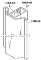
<1>全体構成
本発明の土留壁の構造は、遮水部である土留壁の一部に、通水筒2を設けて構成する。鋼矢板23は、隣接する鋼矢板11を介して連結し、止水壁として遮水性を確保する(図3、図4)。
以下に通水部の構造について説明する。
<1> Overall Configuration The structure of the retaining wall of the present invention is configured by providing the
The structure of the water flow section will be described below.
<2>削孔
土留壁は地盤を開削する前に、開削する範囲の外側に、事前に地下に構築しておく連続した壁体である。
この土留壁は水を通さない遮水性の機能を備えていて、開削側へは水を通さないことが要求される。
この非通水性の土留壁は、例えばシートパイルなどの名称で知られる公知の各種の工法によって構築する。
土留壁は、シートパイルや鋼管矢板のように圧入あるいは打撃による土留壁だけではなく、SMW工法などの名称で知られる地中に柱状の止水柱を連続して形成する構造やRC地中連続壁にも利用することもできる。
いずれの工法によっても一連の土留壁は複数のユニットごとに構築してゆくから、そのユニットとユニットの間に、本発明の構造を形成するための通水縦坑10を削孔する。
したがって、この通水縦坑10は土留壁の線上に、土留壁の一部として構築されることになる。
<2> Drilling hole The retaining wall is a continuous wall body that is built underground in advance outside the area to be excavated before excavating the ground.
This retaining wall has a water-impervious function that does not allow water to pass through, and it is required that water is not passed to the cut-off side.
This non-water-permeable retaining wall is constructed by various known methods known by names such as sheet piles, for example.
The retaining wall is not only a retaining wall by press-fitting or striking like a sheet pile or a steel pipe sheet pile, but also a structure that continuously forms a column-shaped water-stopping column in the ground known by the name of the SMW method, etc. It can also be used.
A series of retaining walls is constructed for each of a plurality of units by any of the methods, and therefore, a
Therefore, this water
<3>通水筒2の構造及び設置
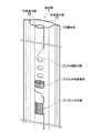
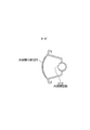
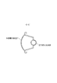
図1のように、通水筒2は、互いに並行する内側通水路21と外側通水路22と、嵌合継手となる鋼矢板23からなる。
内側通水路21と外側通水路22の形状及び、面積は任意に設定できる。例えば、図5のように、各通水路に角パイプなどを用いてもよい。
内側通水路21は、隣接する止水壁で仕切られた開削側の通水材251に接する側壁部分に開口した切り欠き部211と、隣接する通水路間の側壁部分に開口した内側開口部212と、前記切り欠き部211と開口部212の間に設けた止水栓装着部213とからなる。
切り欠き部211は、通水可能なようにスクリーンを設け、止水栓装着部213に止水栓214が装着されると、切り欠き部211と内側開口部212との間の通水が遮断されるように構成する。
外側通水路22は、隣接する止水壁で仕切られた土留壁背面側の通水材252に接する側壁部分に開口した開口部221を設ける。開口部221には通水可能なようにスクリーンを設ける。
通水縦坑10の内部に上記通水筒2を挿入して設置する。
<3> Structure and Installation of
The shapes and areas of the
The
The
The
The
<4>通水材の充填
図3のように、通水筒2と通水縦坑10との間にある空隙に通水材251、252を充填する。
この通水材は硅砂など通常の井戸で用いられるフィルター材を利用できる。
通水材の充填によって、通水縦坑10の背面から流れていた地下水は、通水縦坑10に入り、通水材及び通水筒を経由して下流側へ流出する。
このように、地中に通水縦坑を構築しても、地下水の流れを遮断する現象は発生しない。
<4> Filling with water-permeable material As shown in FIG. 3, the water-
As this water-permeable material, filter materials used in ordinary wells such as dredged sand can be used.
By filling the water flow material, the groundwater flowing from the back of the
In this way, even if a water passage is constructed in the ground, the phenomenon of blocking the flow of groundwater does not occur.
<5>開削前の通水状態
通水筒2に取付けた止水継手と隣接する土留壁を連結することによって、通水性を維持する通水縦坑10と、非通水性の土留壁とは一体となる。
そのために地盤の開削前には、地下水は土留壁の位置ではその流れを遮断されるが、通水筒2を設置した位置では、内側通水路21と外側通水路22を経由し、地下水の流動を確保することができる(図6)。
<5> Water-flowing state before excavation The water-conducting
Therefore, before excavation of the ground, the flow of groundwater is blocked at the position of the retaining wall, but at the position where the
<6>遮水
土留壁に囲まれた開削工事が開始してからは、開削部への地下水の流入は阻止しなければならない。
そのために、開削工事に先立って通水筒2の内側通水路21を閉塞する。
具体的には、内側通水路の内部に設けられた止水栓装着部213に止水栓214を装着する(図10)。
本実施例では、止水栓214は棒状体挿入方式を用いているが、従来あるその他の方式、たとえば、球体埋設方式(図13)などを用いてもよい。
止水栓装着部213は、図11や、図12、図13、図14のようにゴムパッキンや、ゴム止水板を設置し、止水栓214の挿入後の止水性を確実にする。
なお,開削工事期間中は開削内の地下水位は土留壁背面側地下水位より低くなるため,止水栓装着後の内側通水路内の水圧は外側通水路内の水圧より小さくなり,この水圧差により止水栓の押し込み効果が得られ止水性は向上する。また、内側通水路21の止水栓装着部213より上方は、止水栓214、筒状止水栓215、鋼球の設置時のガイドとしての機能を持つ。
<6> Water shielding After the excavation work surrounded by the retaining wall starts, the inflow of groundwater to the excavation part must be prevented.
For this purpose, the
Specifically, the
In this embodiment, the
As shown in FIG. 11, FIG. 12, FIG. 13, and FIG. 14, the water
During the excavation work, the groundwater level in the excavation is lower than the groundwater level on the back side of the retaining wall, so the water pressure in the inner waterway after installing the stopcock becomes smaller than the water pressure in the outer waterway. As a result, the effect of pushing in the water stop cock is obtained, and the water stoppage is improved. Moreover, the upper side of the water
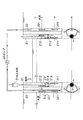
<7>地下水の汲み上げ
以上のように、内側通水路21に止水栓214を装着すると、地下水は開削側へ流れることができず、そこで遮断されてしまう(図15)。
そのため、図10のように、外側通水路22内に集まった地下水をポンプ31でくみ上げる。そして開削場所を越えた位置の外側通水路22から地中に注水する。
こうして開削工事中にも、地下水の流動を確保することができる。
<7> Pumping up groundwater As described above, when the
Therefore, as shown in FIG. 10, the groundwater collected in the
In this way, groundwater flow can be secured even during excavation work.
<8>開削内部の地下水の汲み上げ
開削工事を進めていくうちに、開削内部の地下水位を低下させたい場合は、内側通水路21に筒状止水栓215を装着する(図16)。筒状止水栓215によって、内側通水路21の内側開口部212は閉塞され、外側通水路22から地下水の流入が遮断される(図17)。その後、地上から筒状止水栓215の内部を通過して、内側通水路21の切り欠き部211にポンプ32を設置し、開削内部の地下水を汲み上げる。
なお、内側通水路21及び外側通水路22の両方にポンプ31,32を設置することにより、土留壁により仕切られた開削内部と、その他の地盤に異なる水圧を付加させることもできる。
<8> Pumping up groundwater inside the excavation When the groundwater level inside the excavation is to be lowered while proceeding with the excavation work, a
In addition, by installing the
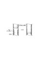
<9>水路の構築
開削が完了して開削底部に至ったら、その開削底部に水路6を設ける(図18)。
この水路6はコンクリートの管体など公知のものを利用できる。
そしてポンプ31,32による汲み上げを停止すれば、通水筒2内に溜まった地下水は、開削底部に設けた水路6を通して流動する。
<9> Construction of water channel When the excavation is completed and the bottom of the excavation is reached, the
The
And if the pumping by the
<10>地下構築物の構築
開削が予定深さまで完了したら、その後に地下構築物7の構築を行う。
その場合に、開削底部に水路6が配置してあれば、構築物7の下面の水路6はそのまま地下水の流路として永久的に利用できる。
なお、水路6を設置する位置は、開削部の底部に限らず、地下水の水位以下の深さであれば、開削部の内部のどこへでも設置することができる。
<10> Construction of underground structure After excavation is completed to the planned depth, the underground structure 7 is constructed thereafter.
In this case, if the
In addition, the position which installs the
10・・通水縦坑
11・・鋼矢板
12・・SMW壁
121・芯材
122・ソイルセメント
2・・・通水筒
21・・内側通水路
211・切り欠き部
212・内側開口部
213・止水栓装着部
214・止水栓
215・筒状止水栓
22・・外側通水路
221・外側開口部
23・・鋼矢板
251・開削側通水材
252・非開削側通水材
31・・ポンプ
32・・ポンプ
6・・・水路
7・・・地下構造物
10. ・ Water shaft 11 ・ ・
Claims (4)
地中に掘削した通水縦坑と、
前記縦坑の内部に設置した、互いに並行する複数の通水路からなる通水筒と、
通水縦坑と通水筒との間に充填した通水材と、
前記通水筒の側部に設けて、前記止水壁と接続する止水継手とより構成し、
前記通水筒は、互いに隣接して設けた外側通水路と内側通水路とにより構成し、
外側通水路は、止水壁で仕切られた土留壁背面側に外側開口部を備え、
内側通水路は、開削側に開口した切り欠き部と、隣接する外側通水路との間の側壁部分に開口した内側開口部と、切欠き部と内側開口部との間に位置する止水栓装着部とを備え、
内側通水路の止水栓装着部に止水栓を装着して、内側通水路の内側開口部と、切欠き部との間を遮水し得るように構成した、通水土留壁。 A water retaining wall for controlling the flow of water between the grounds provided between the water blocking walls and partitioned by the water blocking walls,
A water drain shaft excavated in the ground,
A water pipe made of a plurality of water paths parallel to each other , installed inside the vertical shaft,
A water flow material filled between the water flow shaft and the water pipe,
Provided on the side of the water pipe, and comprises a water stop joint connected to the water stop wall,
The water pipe is constituted by an outer water passage and an inner water passage provided adjacent to each other,
The outer water passage has an outer opening on the back side of the retaining wall partitioned by a water blocking wall ,
The inner water passage includes a cutout portion opened on the cut-off side, an inner opening portion opened in a side wall portion between the adjacent outer water passage passages, and a stop cock located between the notch portion and the inner opening portion. With a mounting part ,
A water retaining wall that is configured so that a water faucet is attached to the water faucet mounting portion of the inner water passage so that the space between the inner opening and the notch of the inner water passage can be blocked.
前記止水栓を内側通水路の止水栓装着部に装着することにより、
内側通水路の断面を閉塞することを特徴とする、
通水土留壁。 The structure of a water retaining wall according to claim 1,
By mounting the stop cock on the stop cock mounting portion of the inner water passage ,
It is characterized by closing the cross section of the inner water passage ,
Water retaining wall.
前記止水栓が筒状部材であり、
前記止水栓を内側通水路の止水栓装着部へと装着することにより、
前記内側通水路を閉塞することを特徴とする、
通水土留壁。 The structure of a water retaining wall according to claim 1,
The stop cock is a tubular member;
By mounting the stop cock to the stop cock mounting portion of the inner water passage ,
The inner water passage is blocked,
Water retaining wall.
開削位置の両側に止水壁をそれぞれ設置し、
前記止水壁間に請求項1乃至3の何れか1項に記載の通水土留壁を設置し、
開削工事の開始前には、
通水材と外側通水路の外側開口部、内側通水路の内側開口部、内側通水路の切欠き部を通して地下水の流動を確保し、
開削工事中には、
内側通水路の止水栓装着部に止水栓を挿入して、内側通水路内の断面を遮断し、
外側通水路の外側開口部を介して外側通水路内に集まった地下水を、
外側通水路からポンプでくみ上げて開削場所を越えた場所において地中に注水することで、地下水の流動を確保し、
開削の完了時には、
開削部の内部に、相対する位置にある土留壁内の通水筒を連結するように水路を構築して、地下水の流動を確保する方法。 A method to ensure the flow of groundwater before and after ground excavation,
Install water barriers on both sides of the excavation position,
A water retaining wall according to any one of claims 1 to 3 is installed between the water blocking walls,
Before the excavation work begins,
Ensure the flow of groundwater through the water passage and the outer opening of the outer water passage, the inner opening of the inner water passage, and the notch of the inner water passage ,
During the excavation work,
Insert the stop cock to the stop cock mounting portion of the inner water conduit, cut off a section of the inner passage within the water channel,
Groundwater collected in the outer water passage through the outer opening of the outer water passage,
By pumping up from the outside waterway and pumping it into the ground at a place beyond the excavation site, the flow of groundwater is secured.
When excavation is complete,
A method of securing the flow of groundwater by constructing a water channel so that the water pipes in the retaining wall at the opposite position are connected inside the excavated part.
Priority Applications (1)
| Application Number | Priority Date | Filing Date | Title |
|---|---|---|---|
| JP2004329674A JP4589084B2 (en) | 2004-11-12 | 2004-11-12 | A retaining wall with a built-in water pipe composed of a plurality of water passages, and a method for ensuring the flow of groundwater using the retaining wall |
Applications Claiming Priority (1)
| Application Number | Priority Date | Filing Date | Title |
|---|---|---|---|
| JP2004329674A JP4589084B2 (en) | 2004-11-12 | 2004-11-12 | A retaining wall with a built-in water pipe composed of a plurality of water passages, and a method for ensuring the flow of groundwater using the retaining wall |
Publications (2)
| Publication Number | Publication Date |
|---|---|
| JP2006138139A JP2006138139A (en) | 2006-06-01 |
| JP4589084B2 true JP4589084B2 (en) | 2010-12-01 |
Family
ID=36619133
Family Applications (1)
| Application Number | Title | Priority Date | Filing Date |
|---|---|---|---|
| JP2004329674A Active JP4589084B2 (en) | 2004-11-12 | 2004-11-12 | A retaining wall with a built-in water pipe composed of a plurality of water passages, and a method for ensuring the flow of groundwater using the retaining wall |
Country Status (1)
| Country | Link |
|---|---|
| JP (1) | JP4589084B2 (en) |
Families Citing this family (3)
| Publication number | Priority date | Publication date | Assignee | Title |
|---|---|---|---|---|
| JP4862706B2 (en) * | 2007-03-15 | 2012-01-25 | 株式会社大林組 | Method for constructing well in underground wall structure and method for using well constructed by this method |
| JP6315700B2 (en) * | 2014-02-13 | 2018-04-25 | 鹿島建設株式会社 | Groundwater control method and system |
| CN114837221B (en) * | 2022-04-15 | 2024-01-02 | 山东建筑大学 | Water passing system for open cut subway station construction and construction method |
Citations (4)
| Publication number | Priority date | Publication date | Assignee | Title |
|---|---|---|---|---|
| JPH10121462A (en) * | 1996-10-16 | 1998-05-12 | Okumura Corp | Formation method of water permeable part in continuous underground wall |
| JP2000087383A (en) * | 1998-09-08 | 2000-03-28 | Shimizu Corp | Cut-off wall and its execution |
| JP2000087385A (en) * | 1998-09-16 | 2000-03-28 | Shimizu Corp | Cut-off wall partition device with valve and its installation method |
| JP2003041575A (en) * | 2001-08-02 | 2003-02-13 | Tobishima Corp | Water flow-through hole forming device and water flow- through hole forming method used for forming water flow-through hole for maintaining underground water flow in impervious wall |
-
2004
- 2004-11-12 JP JP2004329674A patent/JP4589084B2/en active Active
Patent Citations (4)
| Publication number | Priority date | Publication date | Assignee | Title |
|---|---|---|---|---|
| JPH10121462A (en) * | 1996-10-16 | 1998-05-12 | Okumura Corp | Formation method of water permeable part in continuous underground wall |
| JP2000087383A (en) * | 1998-09-08 | 2000-03-28 | Shimizu Corp | Cut-off wall and its execution |
| JP2000087385A (en) * | 1998-09-16 | 2000-03-28 | Shimizu Corp | Cut-off wall partition device with valve and its installation method |
| JP2003041575A (en) * | 2001-08-02 | 2003-02-13 | Tobishima Corp | Water flow-through hole forming device and water flow- through hole forming method used for forming water flow-through hole for maintaining underground water flow in impervious wall |
Also Published As
| Publication number | Publication date |
|---|---|
| JP2006138139A (en) | 2006-06-01 |
Similar Documents
| Publication | Publication Date | Title |
|---|---|---|
| JP5212070B2 (en) | Common well and construction method of regular well | |
| JP5982027B1 (en) | Water leakage countermeasures for tunnels constructed by the Natom method | |
| KR100593786B1 (en) | The construction of waterway for tunnel | |
| JP4074313B2 (en) | Structure of steel sheet pile for water flow and water retaining wall, and its construction method. | |
| JP2009179945A (en) | Well conduit for road and its construction method | |
| JP4727718B2 (en) | Retaining method for retaining wall | |
| JP4589084B2 (en) | A retaining wall with a built-in water pipe composed of a plurality of water passages, and a method for ensuring the flow of groundwater using the retaining wall | |
| JP4358207B2 (en) | Ground reinforcement method for excavated bottom | |
| JP6441692B2 (en) | Underground structure with flood control function and its construction method | |
| KR100481148B1 (en) | Drainage System using Hexa-Tube Connector | |
| KR100666103B1 (en) | Convertible de-pressure drainage method and the system | |
| JP2005330769A (en) | Structure and construction method of water passing earth retaining wall | |
| JP2004278287A (en) | Permeable steel pipe earth-retaining type retaining wall structure | |
| KR200413305Y1 (en) | Convertible de-pressure drainage system | |
| JP3915441B2 (en) | Underground water flow apparatus and underground water flow method | |
| JP4274898B2 (en) | Groundwater flow conservation method | |
| JPH04125B2 (en) | ||
| KR20060061066A (en) | Boring machine for weak ground | |
| JP3892576B2 (en) | Maintenance method of water vein in underground retaining wall construction section | |
| CN217811143U (en) | Miniature cast iron pipe precipitation well structure | |
| JP2611104B2 (en) | Water passing method for continuous underground wall | |
| CN113833524B (en) | Double-hole box culvert for treating karst area tunnel water burst and construction method thereof | |
| JP3895241B2 (en) | Underground continuous wall water passage forming pipe member, underground continuous wall having water passage, and method for forming water passage of underground continuous wall | |
| JP2009249834A (en) | Underground structure | |
| JP2857907B2 (en) | Infiltration type simple recharge drainage method |
Legal Events
| Date | Code | Title | Description |
|---|---|---|---|
| A621 | Written request for application examination |
Free format text: JAPANESE INTERMEDIATE CODE: A621 Effective date: 20070511 |
|
| A977 | Report on retrieval |
Free format text: JAPANESE INTERMEDIATE CODE: A971007 Effective date: 20081128 |
|
| A131 | Notification of reasons for refusal |
Free format text: JAPANESE INTERMEDIATE CODE: A131 Effective date: 20091117 |
|
| A521 | Request for written amendment filed |
Free format text: JAPANESE INTERMEDIATE CODE: A523 Effective date: 20100114 |
|
| A02 | Decision of refusal |
Free format text: JAPANESE INTERMEDIATE CODE: A02 Effective date: 20100511 |
|
| A521 | Request for written amendment filed |
Free format text: JAPANESE INTERMEDIATE CODE: A523 Effective date: 20100804 |
|
| A911 | Transfer to examiner for re-examination before appeal (zenchi) |
Free format text: JAPANESE INTERMEDIATE CODE: A911 Effective date: 20100818 |
|
| TRDD | Decision of grant or rejection written | ||
| A01 | Written decision to grant a patent or to grant a registration (utility model) |
Free format text: JAPANESE INTERMEDIATE CODE: A01 Effective date: 20100907 |
|
| A01 | Written decision to grant a patent or to grant a registration (utility model) |
Free format text: JAPANESE INTERMEDIATE CODE: A01 |
|
| A61 | First payment of annual fees (during grant procedure) |
Free format text: JAPANESE INTERMEDIATE CODE: A61 Effective date: 20100909 |
|
| R150 | Certificate of patent or registration of utility model |
Ref document number: 4589084 Country of ref document: JP Free format text: JAPANESE INTERMEDIATE CODE: R150 Free format text: JAPANESE INTERMEDIATE CODE: R150 |
|
| FPAY | Renewal fee payment (event date is renewal date of database) |
Free format text: PAYMENT UNTIL: 20130917 Year of fee payment: 3 |
|
| R250 | Receipt of annual fees |
Free format text: JAPANESE INTERMEDIATE CODE: R250 |
|
| R250 | Receipt of annual fees |
Free format text: JAPANESE INTERMEDIATE CODE: R250 |
|
| R250 | Receipt of annual fees |
Free format text: JAPANESE INTERMEDIATE CODE: R250 |
|
| R250 | Receipt of annual fees |
Free format text: JAPANESE INTERMEDIATE CODE: R250 |
|
| R250 | Receipt of annual fees |
Free format text: JAPANESE INTERMEDIATE CODE: R250 |
|
| R250 | Receipt of annual fees |
Free format text: JAPANESE INTERMEDIATE CODE: R250 |
|
| R250 | Receipt of annual fees |
Free format text: JAPANESE INTERMEDIATE CODE: R250 |
|
| R250 | Receipt of annual fees |
Free format text: JAPANESE INTERMEDIATE CODE: R250 |
|
| R250 | Receipt of annual fees |
Free format text: JAPANESE INTERMEDIATE CODE: R250 |
|
| R250 | Receipt of annual fees |
Free format text: JAPANESE INTERMEDIATE CODE: R250 |
|
| R250 | Receipt of annual fees |
Free format text: JAPANESE INTERMEDIATE CODE: R250 |