JP4588919B2 - Method and apparatus for setting registration in a multicolor printing machine and multicolor printing machine - Google Patents
Method and apparatus for setting registration in a multicolor printing machine and multicolor printing machine Download PDFInfo
- Publication number
- JP4588919B2 JP4588919B2 JP2001148241A JP2001148241A JP4588919B2 JP 4588919 B2 JP4588919 B2 JP 4588919B2 JP 2001148241 A JP2001148241 A JP 2001148241A JP 2001148241 A JP2001148241 A JP 2001148241A JP 4588919 B2 JP4588919 B2 JP 4588919B2
- Authority
- JP
- Japan
- Prior art keywords
- image
- cylinder
- color
- printing
- color separation
- Prior art date
- Legal status (The legal status is an assumption and is not a legal conclusion. Google has not performed a legal analysis and makes no representation as to the accuracy of the status listed.)
- Expired - Fee Related
Links
Images


Classifications
-
- G—PHYSICS
- G03—PHOTOGRAPHY; CINEMATOGRAPHY; ANALOGOUS TECHNIQUES USING WAVES OTHER THAN OPTICAL WAVES; ELECTROGRAPHY; HOLOGRAPHY
- G03G—ELECTROGRAPHY; ELECTROPHOTOGRAPHY; MAGNETOGRAPHY
- G03G15/00—Apparatus for electrographic processes using a charge pattern
- G03G15/01—Apparatus for electrographic processes using a charge pattern for producing multicoloured copies
- G03G15/0142—Structure of complete machines
- G03G15/0178—Structure of complete machines using more than one reusable electrographic recording member, e.g. one for every monocolour image
- G03G15/0194—Structure of complete machines using more than one reusable electrographic recording member, e.g. one for every monocolour image primary transfer to the final recording medium
-
- G—PHYSICS
- G03—PHOTOGRAPHY; CINEMATOGRAPHY; ANALOGOUS TECHNIQUES USING WAVES OTHER THAN OPTICAL WAVES; ELECTROGRAPHY; HOLOGRAPHY
- G03G—ELECTROGRAPHY; ELECTROPHOTOGRAPHY; MAGNETOGRAPHY
- G03G2215/00—Apparatus for electrophotographic processes
- G03G2215/01—Apparatus for electrophotographic processes for producing multicoloured copies
- G03G2215/0103—Plural electrographic recording members
- G03G2215/0119—Linear arrangement adjacent plural transfer points
-
- G—PHYSICS
- G03—PHOTOGRAPHY; CINEMATOGRAPHY; ANALOGOUS TECHNIQUES USING WAVES OTHER THAN OPTICAL WAVES; ELECTROGRAPHY; HOLOGRAPHY
- G03G—ELECTROGRAPHY; ELECTROPHOTOGRAPHY; MAGNETOGRAPHY
- G03G2215/00—Apparatus for electrophotographic processes
- G03G2215/01—Apparatus for electrophotographic processes for producing multicoloured copies
- G03G2215/0151—Apparatus for electrophotographic processes for producing multicoloured copies characterised by the technical problem
- G03G2215/0158—Colour registration
- G03G2215/0161—Generation of registration marks
Abstract
Description
【0001】
【発明の属する技術分野】
本発明は、様々なインキに割り当てられたカラー印刷ユニットを有しかつ画像胴と、画像、特に静電潜像を画像胴上に形成するための装置と、印刷基板のためのキャリヤと、カラー印刷ユニットから印刷基板に色分解画像を転移させるための画像転移箇所とを有する多色印刷機において見当を設定するための方法に関し、画像胴における画像形成の割り当ては、印刷時の色分解画像の見当の一致を達成するために行われる。
【0002】
本発明は、さらに、様々な印刷インキに割り当てられた、画像胴と、画像、特に静電潜像を画像胴上に形成するための装置と、印刷基板のためのキャリヤと、カラー印刷ユニットから印刷基板へ色分解画像を転移させるための画像転移箇所と、位置を測定するためのセンサと、印刷時に色分解画像の見当の一致を達成するために画像胴上の画像形成箇所の位置を印刷基板に割り当てるための少なくとも1つの設定装置とを有する印刷ユニットを有する多色印刷機において、前記方法に基づき、見当を設定するための装置に関する。さらに本発明は、適切に装備された多色印刷機に関する。
【0003】
【従来の技術】
カラーイラストレーション、特にカラー画像の印刷は、多数の色分解画像が互いに重ねて印刷されることによって行われる。これらは、概して、黄色と、マゼンタと、シアンと、黒とである。必要ならば特別な色が付加される。これらの色を重ねて印刷することにより、全色の合成を達成することができ、印刷品質は、色分解画像の見当の合った重ね印刷に著しく依存する。慣用の自動化されていない印刷プロセスにおいては、刷版は、正確な重ね印刷、すなわち、印刷における見当の維持が達成されるまで、テスト印刷と、これらのテスト印刷と同時に印刷される見当マークとによって補正される、。
【0004】
デジタル印刷プロセスにおいては、画像胴には、静電電荷が生ぜしめられこれらの電荷に付着する着色された顔料が提供されることにより、それぞれ画像形成装置によって画像箇所が書き込まれる。次いで、着色された顔料が印刷基板に転移される。デジタル印刷プロセスにおいては、見当の維持は、画像形成装置が適切に制御されることによって達成することができる。画像の設定は各印刷に対して新たに行われるので、慣用の印刷プロセスのように1−オフ設定を行う必要がないが、プリセット及び制御を提供することができ、これらが、各個々の印刷のための補正を行う。もちろん、これは、静電潜像の提供にのみ当てはまるのではなく、デジタル制御システムによって画像箇所が提供される他の全ての印刷プロセスにも当てはまる。
【0005】
したがって、冒頭に述べたタイプの静電印刷プロセスのために、米国特許第5287162号明細書は、有利には印刷基板のためのキャリヤに見当マークを印刷し、これらの見当マークを装置によって検出することを提案している。この場合、画像形成装置による形成から検出箇所まで見当マークが通過するのに必要とする時間が決定される。次いで、画像が印刷基板に転移された後に見当の維持を達成するために、これらの時間は、画像形成装置が個々の画像胴において画像設定を行う瞬間を決定するために使用される。
【0006】
画像胴の表面に関する速度の違いがある場合、画像胴における画像設定に対する一致を達成することは、不正確につながるので、米国特許第5287162号明細書は、画像胴の様々な角度位置に割り当てられた時間を用いて校正テーブルを記録し、これにより、これらの校正値を用いて、規則的に生じる揺動(これは、ほとんど胴の非円形性により生ぜしめられる)を排除し、このように、各印刷のための補正を行う。
【0007】
しかしながら、高い印刷品質に必要な見当の維持は、極めて高い精度を必要とするので、このような校正テーブルは不十分であり、この校正テーブルにおいて時間値が設定される。画像胴の回転角度に割り当てることができない時間インターバルにおける違いにおいて反映される不規則性を考慮することは不可能である。この不規則性は、校正テーブルを何度も作成するために米国特許第5287162号明細書における提案によっても助成されない。なぜならば、この手段によって、値の長期的な低速の変動を考慮することはできるが、画像胴の角度位置に割り当てることができない短期的な違いは考慮することはできないからである。
【0008】
時間インターバルの間の差に反映されないこのような不規則性の典型的な例は、駆動システムの速度の変動である。なぜならば、この変動は、画像胴又は他の胴の特定の回転角度に割り当てることができず、これらの変動は、画像胴又は他の胴の角度位置といかなる同期をも示さないからである。画像胴の回転角度に割り当てられる、時間値に関して提案されたタイプの校正テーブルによる調節は、誤差を排除するよりむしろ誤差を発生する。したがって、調査において決定されたことは、例えば、電気装置モータの極性が、装置の周波数タイプ速度変動を生ぜしめるアイテムとして生じ、このアイテムは、種々異なる伝送距離のために、全ての画像胴においていかなる同期的発生をも示さず、ひいては、個々の画像胴における時間/位置の差を惹起するということである。これらの周波数タイプ変動は、見当設定において誤差を生じるのに十分である。このタイプの誤りは、画像の開始と同じくらい早くに生じることができるか、又は、画像のサブ領域における誤り、例えば横縞のような見当不正確として、画像品質に現出することができる。駆動システムのこのような周波数のような変動は、画像胴の非円形性等の他の誤差に合併させられるため、許容可能な経費での補正のために校正テーブルをもはや作成することができない。これらのテーブルは、1回転のために又は回転の広範囲な連続のために、画像胴又は他の胴の角度位置にもはや向けられることはできないが、このことが複雑さの結果可能であるならば、反復状態の発生までは複雑な機械構成に関する校正値の曲線は、決定されることが必要である。しかしながら、このように比較的長時間に亘り補正値を作成すること自体は、キャリヤの案内における不規則性、主としてまた温度変化、機械における機械的応力の変化、紙のタイプの変化、トナーの量等の長期的変化、誤差の別の原因もあるということによって妨げられる。短期的に変化しかつ胴の角度位置に関して同期的に動作する誤りと、同様に短期的に変化するが、角度位置に関して同期的に変化しない誤差と、長期的な非同期的な変化との様々な混合は、時間値を用いる提案された校正テーブルの助けによる補正による高い精度の達成を妨げる。
【0009】
【発明が解決しようとする課題】
したがって、本発明は、見当設定の高い精度を、許容可能な経費で、特に、できるだけ欠陥印刷なしに達成することができるように、冒頭に言及したタイプの方法、装置及び印刷機を構成するという目的に基づき。同時に、急速かつできるだけ正確なプリセット及び見当設定の連続的な急速な補正が可能になる。
【0010】
【課題を解決するための手段】
本発明によれば、前記目的は、方法に関して、印刷基板への画像胴における画像形成の位置の、時間と無関係な割り当てが、全ての色分解画像の少なくとも1つの所定の領域に対して実施されることにより達成される。
【0011】
装置に関して、本発明によれば、前記目的は、画像及び基板を支持したエレメントの位置を測定するように設計されたセンサと、少なくとも1つの設定装置とによって達成され、この設定装置は、画像胴における画像形成の位置を、印刷基板に対して、時間とは無関係に、色分解画像の少なくとも1つの所定の領域に関連して割り当てるように設計されている。
【0012】
このような装置を備えた多色印刷機が同様に提案されている。
【0013】
本発明は、記録された時間が互いに関係して配置されるようなレジスタのプリセット及び/又は調節が、誤差の重なりの複雑さの増大につながるという観察に基づく。なぜならば、時間による位置の決定から生じる誤りが、実際の見当誤り原因に付加されるからである。したがって、この別の誤り原因の付加は、対応策のために問題である。なぜならば、このような誤りは短期的に発生し、画像胴の角度位置に関して非同期的に動作する誤差であるからである。
【0014】
本発明は、時間の代わりに、位置が直接に互いに関係して配置されるならば、ほとんどの部分に対して、胴の角度位置に関して同期的に動作しない誤りがもはや生じないという発見に基づく。なぜならば、この誤りは時間位置割当てから生じるからである。したがって、位置の直接的な相互の割当てが、制御又は調節のための基礎とされても、それらは、見当の設定にいかなる影響も与えない。このような直接的な位置割当ては、例えば、距離又は角度位置が互いに割り当てられるように設計されていることができる。本発明による手段によって、駆動システムの周波数タイプの変動又は同様の誤り原因は、もはや見当設定にいかなる影響も与えない。なぜならば、位置は、直接に測定され、もはや時間を介する遠回りなルートによって測定されないからである。
【0015】
本発明は、依然として残留する短いタームの変動が、画像胴又は他の胴の角度位置、すなわち1回転又は回転の短い連続とほぼ同期的に繰り返される状況を達成する。したがって、特定の係属時間のために適用される、各カラー印刷ユニットにおける画像形成のための校正テーブルを作成することもできる。次いで、位置の測定に基づき繰り返し更新される校正テーブルによって、印刷中に長期的な変化を考慮することができる。この校正テーブルの更新は、低速の揺動を補正する。校正テーブルは、本発明の手段の手段によってのみほとんど誤差なしに作成することができる。なぜならば、画像胴の角度位置に対して非同期的に動作する短いタームの誤差が、ほとんどの部分で回避され、もはや、位置割当てに基づく見当の設定に影響しない。しかしながら、本発明は、もちろん、校正テーブルに限定されない。校正テーブルは単に1つの構成であるが、本発明の結果、これらは、初めて精度の設定のために使用することができる。
【0016】
本発明は、画像又は印刷基板にを支持するエレメント配属するほとんど全ての誤り原因を測定しかつ排除することができる。なぜならば、短期的な誤差が、ほとんどの部分のために、角度位置と同期的に生じかつ、回転ごとの繰返しに関連して、より長い期間の誤差を後者から分離することができる誤差に減じるからである。この場合、依然として残留する誤差が、画像胴の直径誤差又は不均衡に基づくか、画像を転移する胴に基づくかは問題ではない。胴カバーの弾性材料の動作によって生ぜしめられる転移誤り、印刷基板のためのキャリヤの機械的な応力のばらつき、又は基板へ画像を転移するために使用される押圧ローラの押圧力の設定のばらつきを、測定及び排除することができる。なぜならば、これらの誤りを、画像又は基板を支持する個々のコンポーネントの角度位置に、同期的な形式で割り当てることができ、ひいては、それぞれ作成される校正テーブルによって補正することができるからである。
【0017】
画像形成のための補正値を決定するために2つの可能性が存在する。反復が生じる限り、サイクルを含む校正テーブルをそれぞれの画像胴のために提供することができる。このようなサイクルは、1回転又は一連の回転であることができる。しかしながら、位置の繰返しまでの全ての位置に関する、画像又は基板を支持するその他のエレメントのための校正テーブルを作成することが考えられ、これにより、全ての校正テーブルの値から計算することによって画像胴上に画像を設定し、互いに調和させたい位置に対する効果に関して生じる全ての差異を排除する。印刷中に位置を連続的に決定することにより、例えば温度差及び機械の応力により生じる低速な揺動を検出しかつ排除することができる。もちろん、使用される印刷基板、画像又はトナーの変更、又はその他の影響により生じる誤差を検出しかつ排除することもできる。
【0018】
本発明による位置の割当ては、校正テーブルを用いて又は用いずに、様々な形式で可能である。したがって、例えば、画像及び基板支持するエレメントの表面の角度位置又は距離を互いに割り当てることができる。角度位置と距離との組合せも可能である。エレメントのうちの1つが基準として用いられると有利である。したがって、方法の1つの態様は、色分解画像のために、キャリヤの所定の位置に関連して、それぞれ画像胴上に少なくとも1つの規定された領域が形成されることを提案している。別の提案は、基準印刷ユニットからの色分解画像の少なくとも1つの所定の領域が、それぞれ、別のカラー印刷ユニットからの色分解画像の少なくとも1つの所定の領域に配属されることであり、次いで、キャリヤの位置に対する割当てが行われる。
【0019】
装置に関して、1つの提案は、少なくとも1つの設定装置が、個々の画像胴における全ての色分解画像の少なくとも1つの所定の領域の形成をキャリヤの所定の位置に対して開始するように設計されることである。前記方法の選択に応じて、設定装置は、種々異なる適切な設計を有することもできる。
【0020】
キャリヤの位置を割り当てるために、キャリヤの駆動ローラの角度位置を使用することが提案される。さらに、画像胴の角度位置を、画像胴の位置の割当てのために使用することができる。さらに、キャリヤの位置の割当てのために、キャリヤの表面の距離を使用することができる。これに対応して、画像胴の表面の距離を、画像胴の位置の割当てのために使用することができる。
【0021】
装置に関して、位置を割り当てるために角度位置を使用するために、少なくとも1つのセンサが角度位置送信機として設計されることが提案され、角度位置を測定しようとする各エレメントに対して1つのセンサが提案される。さらに、少なくとも1つの設定装置は、角度位置を割り当てるように設計されていなければならない。さらに、真円度誤差を検出するための少なくとも1つのセンサと、角度位置と真円度誤差とから位置を決定する少なくとも1つの設定装置とが設けられることができる。目的は、それが、考慮されている色分解画像の所定の領域によってカバーされる実際の距離であり、真円度誤差は、これの正確な測定ではない角度位置につながる。前記のような真円度誤差を検出することにより適切な補正を行うことができ、前記誤りが回避され、それにもかかわらず、位置の比較的単純な測定及び角度位置による位置の割当てが可能である。
【0022】
距離によって位置を決定するためには、少なくとも1つのセンサが距離を測定するように設計されることが提案され、1つのセンサが、距離を測定しようとするそれぞれのエレメントのために提案される。この場合、1つの態様では、センサを、適切な表面に提供された距離マークを検出するように設計することができる。次いで、さらに、少なくとも1つの設定装置を、距離を割り当てるように設計する必要がある。
【0023】
画像胴とキャリヤとの間に配置された付加的な画像転移胴を有する機械のためには、画像転移胴の位置も位置の割当てに含まれることが提案される。画像転移胴の位置を割り当てるために、画像転移胴の角度位置を使用することができ、又は、画像転移胴の表面の距離を、画像転移胴の位置を割り当てるために使用することもできる。装置に関して、画像転移胴の位置を測定するためにそれぞれ少なくとも1つのセンサが設けられていなければならず、これらの位置は、割当てを計算するために少なくとも1つの設定装置に送信されなければならない。この場合に使用されるセンサは、必要ならば真円度誤差を検出するためのセンサと組み合わされた、角度位置送信機であってよく、又は、距離を測定するためのセンサを設けることができる。
【0024】
本発明による方法の1つの態様は、画像開始部であるための、色分解画像の相互に配属した所定の領域を提供する。この割当てを行うために、少なくとも1つの設定装置は、画像胴における画像設定が開始される時のキャリヤの位置を予め規定するように設計されている。
【0025】
全ての画像領域に亘って画像の見当を正確に維持するために、相互に割り当てられる所定の領域が、画像領域を分割することによって形成された色分解画像の領域であると仮定される。色分解画像の領域は、画像箇所の個々の線であるか、色分解画像の画像箇所の多数の線であることができる。前者の場合、画像箇所の線は、色分解画像に割り当てられており、後者の場合、画像箇所の多数の線は、見当を一致させるために割り当てられる。角度位置の割当てに好都合な態様は、領域の画像箇所の多数の線が、画像胴における一定の角度間隔に割り当てることにより生じる。しかしながら、移動方向での位置ではなく、領域の横方向位置を決定及び設定することもできる。領域の横方向範囲に関連した誤りを決定及び補正することも有利である。
【0026】
これらの設定及び補正を行うために、方法に関して、少なくとも1つの設定装置が、画像領域を分割することによって形成された領域を用いて、画像胴上の画像設定が行われる時のキャリヤの位置を予め設定するように設計されている。この場合、領域は、移動方向に対して横方向に、画像領域に亘って延びた帯であってよい。しかしながら、横方向の設定のためには、これらの帯を、再び横方向に分割することができるか、画像箇所の間の距離に直接に関連した横方向設定が行われる。
【0027】
本発明の特に有利な態様では、位置が、見当マークによって決定される。このような位置の決定は、設定するために印刷を行う前と、値の補正を行うために印刷中とに行うことができる。見当マークは、搬送方向に配置されかつ所定の距離だけ離間したエレメントを有すると有利であり、距離が測定される。このような見当マークは、各カラー印刷ユニットにより印刷される。各カラー印刷ユニットによって印刷されたそれぞれのエレメントが複数の列を形成することができるか、又は、離間された多数のエレメントをそれぞれのカラー印刷ユニットによって相前後して印刷することができる。見当マークは、前進しているように(ongoing)又はグループを形成するように設計することができ、見当マークは互いに離間していることができる。その結果、前記位置を測定しかつ割り当てることができる。印刷前に位置を測定したい場合、キャリヤに直接に見当マークを印刷し、位置の決定後に再び見当マークを除去すると有利である。印刷中、見当マークを、印刷基板が載置されていないキャリヤのスペースに印刷すると有利である。しかしながら、見当マークを、試験紙であってよい紙に印刷することも可能であり、また、この目的のために、印刷基板の画像以外の縁部を使用することもできる。装置に関して、見当マークを検出するために少なくとも1つのセンサを設けることができる。このセンサは、所定の距離だけ離間した見当マークのエレメントの間の距離を測定するように設計されていると有利である。
【0028】
全てのカラー印刷ユニットのためのデータを測定した後、測定された位置の分析によって、適切にプログラムされた演算装置によって、画像開始部のための所望の値からの実際の値の偏差が、画像領域を分割することによって形成された他の領域のための所望の値からの実際の値の偏差から分離されると有利である。次いで、値は、画像開始部のための設定装置と、色分解画像の所定の領域のための設定装置とに与えられる。これらの設定装置には、印刷開始前に、画像胴上の位置を決定するための補正値を考慮するように設計された、機械固有の公称値が提供されている。機械が、画像胴が画像を基板に直接転移するような機械であるならば、画像形成箇所から、画像胴への画像転移箇所までの距離は決定的である。機械が画像転移胴を有するならば、画像胴と画像転移胴との間の画像転移箇所から、基板への画像転移箇所までの距離が加えられる。さらに、設定装置は、印刷の開始後に位置のための補正値を考慮するように設計することができる。
【0029】
それぞれの画像胴における画像開始部のための位置を測定した後、それぞれの画像胴における他の所定の領域の画像形成のためのこれらの位置が、第1のものとリンクされ、この順序で制御又は調整のために使用されるように測定されると有利である。このように、まず、色分解画像の開始の位置の見当が、次いで、それぞれの画像領域のための位置が設定される。
【0030】
測定された値の場合、ノイズ、すなわち極めて短期的に生じる変動が、評価のために排除されると有利である(制御の不安定を回避するために)。さらに、測定された位置の値のその他の変動は、長期的な変動から分離され、前記測定された位置の値は、値の大きさ及び繰返しのオーダに関して、胴の反復可能な位置に割り当てることができる。大きさ及び反復のオーダに関して、画像胴の反復可能な位置に割り当てることができる測定された位置の値の変動は、この画像胴のための少なくとも1つの校正テーブルに入れられ、個々の画像胴の画像を形成するために画像形成箇所の位置の誤り補償制御のために使用される。校正テーブルは、色分解画像の画像開始部及び所定の領域のために作成されると有利である。
【0031】
さらに、画像又は基板を支持する別のエレメントのために、所望の位置からの実際の位置の移動サイクルの反復可能な位置に割り当てることができる偏差は、測定され、これらの変動を排除するために画像形成箇所の計算に含まれる。これらは、例えば、適切に構成された機械の場合における画像転移胴である。さらに、画像又は基板を支持するエレメントのために校正テーブルを作成することができ、これにより、画像形成箇所の位置の計算において全ての校正テーブルを含む。移動サイクルの反復可能な位置に割り当てることができない、より長い期間の変動は、校正テーブルの前進する更新(ongoing renewal)によって考慮される。校正テーブルは、それぞれの印刷仕事の前に補正されるが、印刷中に連続的に補正することもできる。装置に関して、このような校正テーブルは、設定装置を制御するための適切なファイルにおいて利用可能である。このようなファイルは、まず、機械固有の公称値として利用可能であり、設定装置によって、印刷が開始する前でさえも、画像胴上の画像形成の位置のための補正値として考慮される。同様に、このような補正値は、画像転移胴上の位置のために考慮することもでき、補正値は同様に、見当を維持するために、画像胴における画像形成の補正を介して行われる。次いで、印刷が行われ、見当マークは、印刷仕事が行われる前にまず印刷され、見当マークの位置が測定され、画像形成位置を決定するために、このように決定された補正位置を考慮する。次いで、印刷仕事の処理中に見当マークを同時に印刷することもでき、これにより、変化を検出し、別の補正を行うことができる。
【0032】
見当に影響する境界条件を、位置の値を補正することによってできるだけ迅速に考慮することが望ましい。したがって、良好な印刷品質のために及び欠陥品を回避するために、このような変化をできるだけ早く位置値の計算に含むことが望ましい。この理由から、より長期的に生じかつ、反復によって、画像又は基板を支持するエレメントの反復可能な位置に割り当てることができない測定された位置値の誤差を、見当の制御のために補正に誤差を生ぜしめる影響変数を検出しかつ含むことによって考慮することが提案されている。このように影響変数を検出しかつ補正に含むことは、記憶された経験値に基づき行われると有利である。この目的のために、設定装置は、印刷開始前に、位置測定のための補正値を考慮するように設計されており、位置測定のための補正値は、検出可能な影響変数に割り当てることができかつ、経験値を備えた少なくとも1つの選択可能なファイルとして利用可能である。このようなファイルの選択は、入力装置を介して行うことができる、すなわち、手入力によって作動させられることができ、また、少なくとも1つの影響変数の少なくとも1つの測定に基づいて設定装置によって選択することもでき、すなわち、補正のためのファイルの含有が、影響変数の測定によって作動させられることができる。さらに、影響変数は、見当に対する影響に関して測定することができ、画像形成に対する補正は、これらの偏差に基づき行うことができる。
【0033】
印刷仕事又は環境的影響に関連した、このタイプの多数の影響変数があり、これらの影響変数は既知であるか測定することができる。この影響変数の1つの例は、印刷機の特定の箇所における温度である。これを考慮するために、少なくとも1つの温度センサを印刷機に配置し、測定された温度を補正の基準にすることが提案される。印刷機の特定の機械部品における機械的応力は、見当の維持に影響することもできる。したがって、この影響変数が、少なくとも1つの応力センサを配置することによって検出され、測定された値を補正のための基準にすることが提案されている。
【0034】
別の影響変数は、紙品位であり、この場合、個々の紙品位に対する経験値が記憶され、新たな紙品位が供給されると、適切なファイルが参照される。印刷したい画像のトナープロフィルも影響を有しており、カラー印刷機が、トナープロフィルを測定するための装置を装備していることによって、又はトナープロフィルが前もって測定され、制御装置に入力されることによって、前記影響を考慮することができる。したがって、種々異なるトナープロフィルに対する経験値が利用可能であると有利である。
【0035】
印刷中に、キャリヤ上での基板のずれが生じるおそれがあるので、このようなずれを補償するために、ずれを検出し、画像形成を補正することもできる。装置に関して、キャリヤ上の基板のずれを検出するためのセンサが設けられており、このずれを補償するために画像形成の位置が補正されるように設定装置が設計されていることが提案される。
【0036】
適切な補正を行うために様々な画像の幅又は様々な紙の幅に対して他の経験値が利用可能である。裏面印刷の画像サイズが表面印刷の画像サイズに対応するように、片側における画像設定後の基板寸法の変化に対する経験値を考慮することもできる。その結果、印刷中の基板の屈曲、色の提供、又は溶着による色の定着により生じる基板寸法の変化を考慮することができる。経験値から、変化前の状態の遡及影響(retroactive influence)を考慮することもできる。例えば、紙品位を変更する場合において、画像胴が新たな紙品位セットのための画像を既に有しているのに対し、前の画像が依然として前の紙品位に印刷されているとき、このような遡及効果が生じる。
【0037】
しかしながら、前記補正に加えて、他の補正も考えられる。繰返しに関して、画像胴の角度位置に割り当てることができないが反復してかつ規則的に生じる位置値の変動は、別々の校正テーブルに入れられ、それぞれの画像胴上に画像を形成するための装置の誤り補償制御のために使用される。例えば、繰返しに関して、印刷基板のためのキャリヤの位置に割り当てることができない位置値の変動は、キャリヤの位置に基づき補正することができ、この補正は、画像胴の位置に割り当てることができる値の位置の補正に加えられ、色分解画像が画像胴上に形成される位置のために考慮される。もちろん、位置値の変動は、その原因を排除することによって回避することもできる。
【0038】
例えば、キャリヤに関して、キャリヤの周期的に生じる不規則を、前もって測定し、計算に設定することができる。又は、キャリヤの駆動ローラの円周を、カラー印刷ユニットの画像転移箇所の間の空間に関して、画像胴への駆動ローラの角度位置の割当てが反復するように寸法決めすることも可能である。これは、キャリヤの駆動ローラの円周を、カラー印刷ユニットの画像転移箇所の間の距離に挿入することを可能にすることによって行われてよい。この場合、円周を、半分として、又は有利には整数として挿入することが可能であってよい。このタイプの発展は、主に、駆動ローラが画像胴をキャリヤ、場合によっては画像転移胴を介して駆動する場合に有利である。なぜならば、駆動ローラの非円形性より生じる不規則が、全てのカラー印刷ユニットに同時に作用し、もはや見当の設定に影響しえないからである。前記構成は、キャリヤの距離が、駆動ローラに配属した角度位置送信機によって測定される場合にも有利である。なぜならば、角度位置送信機によって見当合せされない、駆動ローラの非円形性から生じるキャリヤの速度のばらつきが、もはや測定される必要がないからである。なぜならば、キャリヤの速度のばらつきの影響は、前記方法において既に排除されているからである。
【0039】
しばしば、測定されたデータに基づく位置値の完全に正確な決定は不可能である。例えば、測定は通常必然的なばらつきを有しており、ばらつきは、画像の幅に亘ってばらつきを生ぜしめるおそれがあり、又は、振動の結果、短期的な変動が生じる。このような場合に対し、測定された距離値の許容帯域幅内で、補正が所定の範囲に対して設定されることが提案される。
【0040】
例えば、搬送方向に対して横方向の様々な位置値の場合、平均値を設定することができる。この場合、平均値を計算するために、測定された偏差を加重することができ、例えば二次の加重が提案される。画像品質への偏差の影響が最小限であることを考慮して、他の加重がもちろん可能である。有利には中央の範囲にある、カラー印刷ユニットからの値は、中央の範囲にある、基準印刷ユニットからの値と整合させられる。
【0041】
画像が形成される画像胴の位置の計算に関して、印刷基板の到着が検出され、次いで、画像胴における画像の設定のそれぞれの開始のための位置が、位置として、例えば、印刷基板のための検出箇所から始まるキャリヤの距離として決定されることが提案される。これらの計算は、まず、前もって決定されかつ入力された値に基づき行われ、後続の補正は、印刷中に位置を測定することに基づき必要な位置に対する補正を決定する少なくとも1つの装置によって行われ、これらを、行われるための設定装置に送信する。
【0042】
測定された値の分析は、既に述べた形式で行うことができ、画像開始部のための位置のばらつきが、画像領域を分割することによって形成された残りの領域のための位置のばらつきから分離され、見当を設定するための装置に関して、画像開始部のための補正を決定するための少なくとも1つの装置が、キャリヤの位置を測定するためのセンサと、見当マークを検出するためのセンサとに接続されることが提案される。このように、補正を決定するための装置には、前もって計算された位置からの見当マークの位置の偏差に関するデータが与えられ、その結果、補正を計算し、補正を開始することができる。
【0043】
さらに、画像領域を分割することにより形成された、色分解画像の領域のための補正を決定するための装置は、キャリヤの位置を測定するためのセンサと、見当マークを検出するためのセンサとに接続されることが提案される。このように、見当マークによって見当合せされる位置からの、予め計算された位置の間のばらつきを、画像領域を分割することにより形成された、色分解画像の領域のために、測定することができ、補正を計算することができる。
【0044】
画像開始部のための開始信号は、画像領域が分割されて形成された領域の割当てのために介し信号を同時に与える画像開始部のための開始信号の出力のための装置によって、画像領域が分割されて形成された他の領域の開始と関連づけられる。前記装置は、画像胴の位置を測定し、これらの位置を、画像領域が分割されて形成された領域に割り当てるためのセンサに接続されている。
【0045】
正確な見当設定のために必要な位置を計算するために十分な時間を有するために、印刷機に供給される印刷基板を検出するためのセンサが、印刷機へ印刷基板の距離に配置されかつ設定装置に接続され、印刷基板が検出された時に、画像形成箇所の位置の相互の割当ての計算が開始されることが提案される。印刷機への印刷基板の距離に設けられたこのセンサは、印刷基板の前縁を十分に正確に検出することができないので、印刷基板の前縁の正確な検出のためのセンサが、キャリヤ上に配置されかつ、印刷基板がこのセンサから個々の画像設定プロセスの開始の位置までをカバーする距離を計算する装置に接続され、これにより、正しい位置において画像設定を開始する。しかしながら、十分な距離が設けられているならば、もちろんキャリヤ上に配置されたセンサが両機能を行うこともできる。
【0046】
もちろん、見当を設定するための装置が、前記全ての方法を行うことができるように、またはその逆に設計することができる。
【0047】
さらに、本発明に基づき提供される多色印刷機は、前記全ての装置特徴を有することができ、前記方法特徴に基づき動作するように設計することができる。
【0048】
【発明の実施の形態】
図1は、多色印刷機1の、本発明による機能の概略図を示している。概して、多色印刷機1は、図4に示したように、4つのカラー印刷ユニット6,6′,6′′,6′′′を有している。図1においては、本発明による機能を説明するのに十分であるため、2つのカラー印刷ユニット6,6′のみが示されている。図面は、通常の場合、4つ、又は場合によってはそれ以上のカラー印刷ユニット6,6′,6′′,6′′′が前述の形式で見当を一致させられなければならないと理解されるべきである。
【0049】
図示した各カラー印刷ユニット6,6′,...は、画像胴2,2′,...を有しており、これらの画像胴には、画像を形成するための装置のアイテム3,3′,...が配属している。これは、概して、静電潜像の形式における、デジタル画像形成であるか、又は例えばインキジェットによるような、直接的な又はその他のデジタル画像形成によってである。多色印刷機1は、画像胴2,2′,...からの画像の転移が直接に印刷基板15へ行われるように設計することができる。しかしながら、図示した多色印刷機1は、画像転移胴13,13′,...をも有しており、画像は画像胴2,2′,...から画像転移胴13,13′,...へ画像転移箇所53,53′,...において転移される。画像転移胴13,13′,...から、画像は次いで最終的に印刷基板15へ画像転移箇所5,5′,5′′,5′′′において転移される。
【0050】
印刷基板15は,キャリヤ4によって矢印33の方向に搬送される。処理中には、印刷基板は、相前後して画像転移箇所5,5′,5′′,5′′′を通過する。カラー印刷ユニット6,6′,6′′,6′′′の各画像転移箇所5,5′,5′′,5′′′において、色分解画像7,7′,...が印刷基板15に転移される。見当設定によって解決すべき問題は、色分解画像7,7′,...は、高い印刷品質を得るために極めて正確に互いに重ねて印刷されなければならないということである。静電式又は同様のデジタル印刷プロセスの場合、画像胴2,2′,...上の画像は、装置3,3′,...によって各印刷ごとに新たに形成され、次いで、装置61,61′,...によって再び除去される。このような装置61,61′,...は図2及び図4に示されている。
【0051】
より明瞭に示すために、印刷機の全ての部材が全ての図面に示されているわけではないが、図1、図2及び図4は、典型的な実施例を示しており、完全性を達成するために、機械図を形成するために組み合わされるべきである。
【0052】
画像は、自由に選択可能な画像形成箇所11,11′,...において、画像胴2,2,...上に設定することができるので、デジタル印刷プロセスを用いる印刷機における見当の設定は、画像が印刷基板15に転移されるときに見当の維持が達成されるような形式で、選択された個々のカラー印刷ユニットにおける画像形成箇所11,11′,...によって遂行される。従来技術では、このために、画像基板が画像転移箇所に到達するまでにこの画像基板が必要とする時間が記録された。これらの時間は、画像の形成から印刷基板への転移までに画像が必要とする時間と合致させられる。したがって、印刷基板の検出が行われ、次いで、各カラー印刷ユニットに対し、画像設定のための瞬間が計算され、これにより、全ての色分解画像の見当の維持が達成される。
【0053】
色分解画像7,7′,...の見当の一致を達成するために、本発明では、色分解画像7,7′,...の形成箇所11,11′,...の位置が、互いに及び印刷基板15の位置25,25′,...と合致させられる。この場合、全ての位置11,11′,...,8,8′,...,9,9′,...,12,12′,...,14,14′,...,22,22′,...,24,24′,...を、距離又は角度位置として規定することができ、色分解画像7,7′,...の形成の位置11,11′,...を計算するために使用することができる。
【0054】
例えば、画像を形成するための装置3,3′,...の画像形成箇所11,11′,...から、画像転移箇所5,5′,5′′,5′′′までの、色分解画像7,7′,...の距離8,8′,...,9,9′,...を、キャリヤ4上の印刷基板15の距離12,12′,...,14,14,...,22,22′,...と合致させることができる。距離12,12′,...,14,14′,...,22,22′,...は、検出箇所23から、印刷ユニット6,6′,6′′,6′′′の画像転移箇所5,5′,5′′,5′′′まで、キャリヤ4を用いて印刷基板15によって被覆される。このような割り当ては、画像胴の角度位置8,8′,...と、画像転移胴13,13′,...の角度位置9,9′,...とを使用することにより、適切な形式で行うことができる。さらに、キャリヤ4の距離12,12′,...,14,14′,...を、キャリヤ4の駆動ローラ52の角度位置12,12′,...,14,14′,...として測定し、設定のために使用することができる。前記及びその他のタイプの位置決定を特徴付けるために、以下のテキストでは、位置11,11′,...,8,8′,...,9,9′,...,12,12′,...,14,14′,...,22,22′,...,25,25′,...が言及される。
【0055】
見当の精度を達成するために、一方では、色分解画像7,7′,...の画像開始部10が整合させられ、他方では、しかしながら、色分解画像7,7′,...の規定された領域10,10′,...も整合させられる。これらの領域は、画像開始部10において得られた見当精度を、印刷される画像全体に亘って維持するために働く。
【0056】
本発明による位置の割り当ては、印刷基板15の前縁24のための検出箇所23として働くセンサ23を用いて開始する。しかしながら、個々のカラー印刷ユニット6,6′,6′′,6′′′の色分解画像7,7′,...のための演算オペレーションを、キャリヤ4の上流に配置された、印刷基板を検出するためのセンサ4によって、前方へ移動させることが可能であり、これにより、印刷機1へ供給される印刷基板15を印刷機1への途中で既に検出し、色分解画像7,7′,...の割り当てのための演算オペレーションを始動する。
【0057】
見当を設定するための装置は、検出箇所23からの位置25,25′,...を、例えば、印刷基板15がキャリヤ4上でカバーしなければならない距離22,22′,...として計算する。これらの位置25,25′,...は、印刷基板15がこれらの位置に到達したときに画像胴2,2,...上の画像の設定が開始することによって規定される。位置25,25′,...は、いわゆる、印刷基板15の前縁24の距離が、画像転移箇所5,5′,5′′,5′′′までの色分解画像7,7′,...の前縁10、又は前記角度において示された角度の同一性、に等しくなる位置である。もちろん通常は図4に示したように少なくとも4つのカラー印刷ユニット6,6′,6′′,6′′′に対してこの位置の合致が行われなければならない。つまり、図1は単純化されている。
【0058】
画像設定の始箇所の位置25,25′,...に到達する時、画像開始部10は、印刷基板15の前縁24と同じ距離をカバーしなければならない。しかしながら、印刷基板が、印刷されない縁部を有することが考慮されておらず、この縁部は、もちろん、計算に含まれなければならない。位置25,25′,...からはじめて、印刷基板15が距離又は角度14,14′,...(例えば駆動ローラ52の)をカバーすると、画像胴2,2′,...上の色分解画像7,7′,...が、距離又は角度8,8′,...をカバーする。次いで、画像転移胴13,13′,...への画像の転移53,53′,...が行われる。次いで、画像転移胴13,13′,...上の色分解画像7,7′,...の別の距離又は角度9,9′,...は、キャリヤ4上の印刷基板15の距離又は角度12,12,′...に相当する。このように、印刷基板15が、個々の画像転移箇所5,5′,5′′,5′′′に到達すると、それぞれ適切な色分解画像7,7′が、適時にではなく、同一の位置において供給される。その結果、印刷基板には、カラー印刷ユニット6において搬送方向33に第1の色分解画像7が提供され、次いで、第2の印刷ユニット6において第2の色分解画像7が提供され、さらに続けて他の色分解画像が提供される。したがって、図1を見ると、右側の印刷基板15はまだ色分解画像を有しておらず、中央の印刷基板15はカラー印刷ユニット6からの色分解画像7を有しており、左側の印刷基板15は、色分解画像7及び7′を有している。次いで、必要であれば、さらに特別な色によって、別のカラー印刷ユニット6′′及び6′′′において印刷が完成される。この場合印刷基板15は、ローラ52及び52′上を走行するベルトとして設計されたキャリヤ4によって搬送される。一方のローラは駆動ローラ52であり、他方のローラはガイドローラ52′である。色分解画像7,7′,...を印刷基板15に転移させるために、画像転移箇所5,5′,5′′,5′′′において圧胴20が取り付けられている。これらの圧胴は、静電潜像を用いる印刷プロセスにおいて、帯電されたカラー粒子を印刷基板15へ転移させる。これらの圧胴は図1及び図2には示されていないが、その位置は図4に示されている。
【0059】
図1には、画像胴2,2′,...の回転方向16,16′,...及び画像転移胴13,13′,...の回転方向60,60′も示されている。キャリヤ4の搬送方向は矢印33によって示されている。
【0060】
図2は、位置8,8′,...,9,9′,...,12,12′,...,14,14′,...,22,22′,...,25,25′,...の本発明による設定を行うための見当設定装置の基本的構成を示している。位置を互いに割り当てることができるように、まず、画像又は基板の搬送のために相対的な位置を占める全てのエレメントを測定する必要がある。これは、まず、印刷基板15のためのキャリヤ4である。キャリヤ4の位置は、角度位置送信機として設計されたセンサ27によって測定することができる。しかしながら、択一的に、キャリヤ4上の距離マークを検出するセンサ32をキャリヤ4上に配置することもできる。さらに、位置を測定するために、センサ29によって見当マーク17,17′,17′′,17′′′を検出することができる。画像胴2,2,...の位置を測定するために、図示の典型的な実施例では、それぞれ角度位置送信機として設計されたセンサ26,26′,...が使用され、画像転移胴13,13′,...の位置を測定するために、同様に角度位置送信機として設計されたセンサ28,28′,...が使用される。しかしながら、距離マークによって距離を測定するセンサ26,26′,...を、胴2,2′,...,13,13′,...に配置することもできる。このことは、このようなセンサ26,26′,...の配列によって図4に示されている。
【0061】
キャリヤ4の上流には、印刷基板15を印刷機1に供給するための搬送ベルト45が配置されている。印刷基板15がセンサ44を通過する時、位置8,8′,...,9,9′,...,12,12′,...,14,14′,...22,22′,...,25,25′,...の割当ての計算が開始する。印刷基板15の前縁24がセンサ23に到達すると、計算の準備ができ、装置46,46′が始動され、この装置は、距離22,22′の被覆を見当合せし、画像開始部10に対する開始信号48,48′と、色分解画像7,7′の領域10,10′,...,10nに対する開始信号49,49′とを提供する。距離22,22′を測定するために、又は、位置25,25′,...に到達したことを検出するために、開始信号48,48′,...,49,49′,...を与えることができるように、装置46,46′,...は、位置を測定する全てのセンサに接続されている。これらは、画像胴2,2′,...の位置を測定するためのセンサ26,26′,...と、キャリヤ4の位置を測定するためのセンサ27と、画像転移胴13,13′,...の位置を測定するためのセンサ28,28′,...とである。さらに、位置25,25′,...を計算するための装置46,46′,...は、設定装置30,30′,...に接続されており、これらの設定装置は、画像開始部10のための位置12,12′,...及び14,14′,...を計算する。画像開始部10のための開始信号48,48′,...と、画像領域を分割することによって形成された色分解画像7,7′,...の領域10,10′,10′′,...,10nのための開始信号49,49′,...とは、前縁24及び、印刷基板15における画像の将来の始箇所が、画像胴2,2,...上の画像設定の開始の位置25,25,...に到達したときに与えられる。これに関しては図1が参照される。
【0062】
領域10,10′,...10nのための開始信号49,49′,...は、画像胴2,2′,...の位置に対して正確に割り当てられなければならないので、装置47,47′,...と、画像胴2,2′,...の位置を測定するためのセンサ26,26′,...との間は接続されている。装置46,46′,...と装置47,47′,...との接続51,51′,...は、画像開始部10と同時に領域10,10,...,10nを開始するために使用される。装置47,47′,...は、色分解画像7,7′,...の領域10,10′,...,10nを、画像胴2,2′,...の位置に割り当てるために使用される。
【0063】
所定の領域10,10′,...,10nの位置8,8′,...,9,9′,...,12,12′,...,14,14,...24,24′,...,25,25′,....を計算するために、設定装置30,30′,...,31,31′,...が使用される。この場合、設定装置30,30′,...は、画像開始部10の距離8,8′,...,9,9′,...を計算するために使用され、設定装置31,31′,...は、色分解画像7,7′,...の領域10,10′,...,10nの距離8,8′,...,9,9′,...を計算するために使用される。設定装置30,30′,...,31,31′,...は、位置の計算に必要な全ての情報を与えられ、ひいては、画像形成箇所が、個々の位置に関して、位置12,12′,...,14,14′,...との位置8,8′,...,9,9′,...の調和に対応するような命令を、画像形成装置3,3′,...に与えることができるように、設計及び相互接続されている。この調和は、印刷基板15が機械固有の公称値によって印刷される前に、印刷及び見当マーク17,17′,17′′,17′′′の検出による補正を用いて、また、印刷基板15の印刷中にも行われ、印刷中にも見当マーク17,17′,17′′,17′′′を検出することができる。このように、それぞれの画像設定動作の間にプリセットを補正することができる。画像胴2,2′,...から画像転移胴13,13′,...,へ色分解画像7,7′,...を転移した後、画像残留物が、画像胴2,2′,...から、再び装置61,61′,...によって除去される。同様に、画像転移胴13,13′,...には、画像残留物を除去するための装置62,62′,...が配属している。
【0064】
画像形成のための位置11,11′,...の第1の設定は、全ての関連するデータ8,8′,...,9,9′,...,12,12′,...,14,14′,...,22,22′,...,25,25′,...を受け取る設定装置30,30′,...,31,31′,...によって行われる。このデータを利用可能にするために、基板15に印刷する必要はなく、実際には、印刷プロセスは全く必要ではない。なぜならば、例えば距離又は角度8,8′,...,9,9′,...及び12,12′,...,14,14′,...,22,22′,...,25,25′,...の位置の測定及び割当てが十分であるからである。
【0065】
まず最初に、設定装置30,30′,...は、画像開始部10の位置8,8′,...,9,9′,...の機械固有の公称値34,34′,...を有している。同様に、設定装置31,31′,...は、機械固有の公称値35,35′,...、特に、色分解画像7,7′,...の領域10,10′,...,10nの位置8,8′,...,9,9′,...に関連した公称値35を有している。これらの機械固有の公称値35,35′,...は、高い精度を達成するために連続的に補正され、印刷作業が行われる前に初めて行われる。このために、設定装置30,30′,...,31,31′,...には、画像胴2,2′,...の位置を測定するためのセンサ26,26′,...によって、画像胴2,2′,...上の位置8,8′,...に関連した補正値が与えられる。さらに、設定装置30,30′,...,31,31′,...には、画像転移胴13,13′,...の位置9,9′,...のための補正値37,37′,...が与えられる。これらの補正値37,37′,...は、画像転移胴13,13′,...の表面の角度位置又は距離を測定するためのセンサ28,28′,...から得られる。カラー印刷ユニット6,6′,6′′,6′′′と、センサ23との位置との間の距離64は、機械固有の公称値として入力することもできる。公称値に対する補正は、様々な影響に基づき、例えば、測定された温度又は印刷機1における機械的な応力に基づき必要であることができる。
【0066】
しかしながら、別の環境が距離の計算に影響するので、設定装置30,30′,...,31,31′,...には、別の補正値38,38′,...も提供される。これらの補正値は、紙品位、トナーの塗布、画像の幅、紙幅、裏面印刷が行われているかどうか、温度、機械部品における応力、キャリヤ4上における印刷基板15のずれ等に対する経験値であってよい。これに関しては前記説明が参照される。これらの補正値38,38′,...は、経験値として利用可能である。補正値は、入力装置(図示せず)によって設定装置30,30′,...,31,31′,...に与えることができるか、補正値を、例えば温度又は応力の測定に基づき設定装置30,30′,...,31,31′,...へ送ることができる。
【0067】
機械固有の公称値34,34′,...,35,35′,...及び補正値38,38′,...が、校正テーブルとして利用可能であってよい。この場合、機械固有の公称値34,34′,...,35,35′,...は、有利には画像胴2,2′,...の角度位置に割り当てられる。しかしながら、既に前述した他の割当ても可能である。この場合、画像胴2,2′,...における画像形成箇所11,11′,...を計算する場合、多数の校正テーブルが含まれていなければならない。次いで、他の値のための校正テーブルは、例えば、種々異なる温度又は種々異なる応力に割り当てられる。さらに、これらの校正テーブルは、画像胴2,2′,...の角度位置に割り当てることもできる。経験値として記憶された補正値38,38′,...は、ファイル39,39′,...として呼び出せるように記憶されている。
【0068】
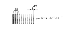
試験動作に基づき、又は印刷中に、別の補正をフィードバックとして考慮することができる。これらの別の補正は、例えば、カラー印刷ユニット6,6′,...によってキャリヤ4上に印刷されかつ見当マーク17,17′,17′′,17′′′を検出するためのセンサ29によって検出される見当マーク17,17′,...によって決定されてよい。これらの見当マーク17,17′,...の場合、見当マークの位置によってキャリヤ4に割り当てられかつ、例えば規則的に配置されたエレメント18を有することが必須である。この場合、1列の離間したエレメント18を印刷することができ、この場合、それぞれ1つのエレメント18が連続的にカラー印刷ユニット6,6′,...によって印刷される。しかしながら、カラー印刷ユニット6,6,...は多数の離間したエレメント18を相前後して印刷することもできる。見当マーク17,17′,...が、前進する帯(ongoing band)として印刷されないならば、見当マークのそれぞれのグループの間の距離を測定することもできる。まだキャリヤ上に印刷基板15が存在しないならば見当マーク17,17′,...をキャリヤ4上に直接印刷することができ、見当マークは、印刷基板15が載置されていないキャリヤ上の箇所、試験紙又は印刷基板15上の無画像箇所、例えば縁部、に印刷されることができる。
【0069】
センサ29からの測定値は、画像開始部10のための補正を決定するための装置40,40′,...へ送られ、これらの装置40,40′,...は、設定装置30,30′,..に補正42,42′,...を与える。対応して、見当マーク17,17′,...を検出するためのセンサ29からの値は、色分解画像7,7′,...の領域10,10′,...,10nのための補正43,43′,...を決定するための装置41,41′,...に与えられる。これらの装置41,41′,...は、補正43,43′,...を設定装置31,31′,...にも与え、これにより、所定の領域10,10′,...,10nのための位置を、フィードバックに基づき補正することができる。
【0070】
もちろん、図2は、簡潔に示すために2つの印刷ユニット6,6′のみに限定されているが、実際には4つの印刷ユニット6,6′,6′′,6′′′が設けられている。したがって、もちろん、キャリヤ4は対応してより長く構成されている必要がある。さらに、印刷基板15を印刷機1に供給するための搬送ベルト45が、短縮された形式で示されており、センサ44からセンサ23までの印刷基板の距離は、この距離が覆われるときに、位置8,8′,...,9,9′,...,12,12′,...,14,14′,...,22,22′,...,25,25′,...のための演算オペレーションを実施することができるように、著しくより長い。通常4つの印刷ユニット6,6′,6′′,6′′′が設けられているので、図示した印刷ユニット6及びに配属された前記エレメントも4つ存在する。択一的に、全てのエレメントを含むコンピュータが設けられている。
【0071】
図3aは、時間測定に基づき設定された機械における見当偏差を示している。
搬送方向33で距離56に沿って測定される測定された箇所の場合に見当の所望の値54からの偏差55がプロットされている。図示したように、測定された個所57は、0ラインとして示された所望の値54からの、振動状の偏差を示している。
【0072】
図3bは、発明の原理に基づき設定された印刷機1における見当偏差を示している。位置に基づき行われる見当設定によって、偏差の著しく低い設定が達成される。この場合にも、所望の値54からの偏差55は、搬送方向33に沿った測定された個所からの距離56に対してプロットされている。原因、例えば、駆動装置の電気モータの磁極が依然として存在する場合でさえも、時間制御の場合のような振動状の偏差はこの場合生じない。その理由は、このタイプの振動は、時間に対する位置の割当てに基づき、ひいてはあらゆる制御に影響することができないからである。
【0073】
図4は、4つのカラー印刷ユニット6,6′,6′′,6′′′を有する多色印刷機1の概略図を示している。これは、多色印刷機1の通常の構造であるが、さらに印刷ユニットが設けられていてもよい。参照符号は、図1及び図2に関連した実施例において既に説明した印刷機の、既に説明した全ての図示されたコンポーネントと同じである。典型的な実施例として示された印刷機は、4色印刷ユニット6,6′,6′′,6′′′を有しており、各印刷ユニットには、図1及び図2に示したエレメントが割り当てられている。
【0074】
さらに、2つのカラー印刷ユニット6,6′又は6′,6′′又は6′′,6′′′の間の距離64もここに示されている。このような距離64は、駆動ローラ52のあらゆる非円形性が全ての印刷ユニット6,6′,6′′,6′′′に同時に影響するように測定されると有利である。この均一な影響の結果、この誤りの効果は回避される。このために、駆動ローラ52の円周は、距離64に対応していてよいが、この距離64の分数であっても又は整数倍であってもよい。機械の寸法決めの観点から、円周と距離64との同一又は全体的倍数が考慮されてよい。
【0075】
図5は、位置を測定するために特に有利な見当マーク17,17′,...を示している。これらの見当マーク17,17′,...は、離間したエレメント18を有している。エレメント18は、いわば、位置を距離として規定する、又は例えば角度間隔として示すスケールを形成しており、色分解画像7,7′,...の位置を相対的に及び印刷基板15に対して測定することができる。
【0076】
図6は、見当マークを検出するための基本的なスケッチを示している。それぞれの場合、見当マーク17,17′,...は、カラー印刷ユニット6,6′,...(1つののみが象徴的に示されている)によって印刷される。前記マークの位置は、見当マーク17,17′,...を検出するためのセンサ29によって測定される。このために、見当制御システムには、基準線66が規定されており、キャリヤ4上の基板15に割り当てられている。基板15を備えたこの基準線66が、見当センサ29の前方における特定の位置に到達すると、見当センサが活性化され、基準線66に対する見当マーク17,17′,...の距離を測定する。この場合、印刷基板15の前縁24のための検出箇所23からの基準線66のそれぞれの距離65と、この基準線66からの見当マーク17,17′,...の所定の距離とは、例えば、距離として測定することができる。しかしながら、それらをキャリヤ4の駆動ローラ52の角度位置に割り当てることが有利に提案され、これらの角度位置は、角度位置送信機として設計されたセンサ27によって測定される。データは、上述した形式で、画像形成11,11′,...のための補正を決定するための装置40,40′,...,41,41′,...へ伝送される。
【0077】
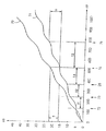
図7は、時間とは無関係な位置割当ての例を示している。図では、画像胴及び画像転移胴の角度位置68が、印刷基板のためのキャリヤ4の位置69に対してプロットされている。しかしながら、1つの画像胴2の角度位置70と、1つの画像転移胴13の角度位置71のみが示されている。別の画像胴2等の角度位置は、曲線70及び71に対してシフトされた曲線によって示されなければならない。簡潔に示すために、これは省略されている。図は、画像胴2の角度位置と、画像転移胴13の角度位置とが、印刷基板15のためのキャリヤ4のそれぞれの位置69に配属していることを示している。したがって、このように、時間とは無関係な位置の割当てが行われ、正しい位置において特定の動作を開始する。
【0078】
印刷のための第1の準備は、位置72において開始される。これは、センサ44によって印刷基板15を検出するための位置であり、センサ44は、印刷基板15を多色印刷機1へ供給する動作を見当合せする。この時箇所から、色分解画像7,7′,...の画像形成11,11′,...の計算が行われ、相対的割当てが計算される。位置73において、印刷基板15はセンサ23によって検出され、ひいては、キャリヤ4上での印刷基板15の正確な位置が決定され、その結果、キャリヤ4への色分解画像7,7′,...の画像形成11,11′,...正確な割当てが可能である。位置72と位置73との間において、印刷基板は距離21を覆う。位置73における印刷基板の検出により、駆動ローラ52の距離又は角度位置が、位置25を決定するために計算される。これは、画像胴2における色分解画像7の画像形成11のが開始するキャリヤ4の位置である。キャリヤ4の距離14の後に、位置74において、画像胴2から画像転移胴13への色分解画像の転移が開始される。キャリヤ4のさらなる距離12の後、キャリヤ4は、画像転移胴13から基板15への色分解画像の転移を開始するための位置75に到達する。この場合、キャリヤ4の距離14及び12は、画像胴の角度位置8と画像転移胴13の角度位置9とに割り当てられる。重要な要因は、画像形成、ひいては色分解画像7,7,...の転移が、これらの位置割当てによって決定されることである。色分解画像7の画像の開始部10に対応する形式で、全ての色分解画像7,7′,...の所定の領域10,10′,10′′,...,10nの位置割当てが行われる。
【0079】
しかしながら、本発明による位置割当ては、胴2,2′,...,13,13′,...及びキャリヤ4における距離長さが等しいことを意味しない。なぜならば、例えば、画像胴2,2から画像転移胴13,13′,...へ色分解画像7,7′,...を転移する間に、オーバドライビングが生じるからである。これは、胴カバーのゴムのような特性の結果、同じ距離に亘る回転が生じず、画像転移胴13,13′,...の表面は、理想的な胴が互いの上で転動する場合よりも速く移動させられることを意味する。さらに、スリップが生じ、同様に、スリップにより、正確な距離−長さの割当てが不可能となる。距離長さの違いに影響するこのタイプの現象は、画像形成11,11′,...の正しい位置を決定するために、位置の割当ての間に、例えば、キャリヤ4の位置69に対する、画像胴2,2′,...及び画像転移胴13,13′,...の角度位置の割当ての間に、考慮されなければならない。距離が互いに対して関係を持たされるならば、例えば、オーバドライブ、スリップ及び類似の現象の結果として生じる距離の差異の補正も、計算に含まれねばならない。
【0080】
基本的な割当てが、機械固有のパラメータとして入力され、次いで、これらのパラメータが、印刷の前及び印刷中に連続的に監視されかつ補正されると有利である。これらの補正により、異なるトナー塗布又は多数の別の原因の結果生じる、オーバドライブ、スリップ及び類似の変化を補償することができる。これらの値が印刷基板の幅に亘って変化する場合、これらの割当ては平均に基づくと有利である。
【0081】
示された典型的な実施例は、単に、本発明を説明し、同時に、有利な実施例を構成するために役立つ。冒頭に述べられた方法、及び本発明の装置は、もちろん、機械において、多数の形式で実施することができる。言及した、位置の測定に関する択一例が可能であるのみならず、もちろんデータの実際の獲得及び処理は異なる形式で設計することができる。
【図面の簡単な説明】
【図1】多色印刷機の本発明による機能を示す概略図である。
【図2】多色印刷機の見当設定装置の基本構造を示す図である。
【図3a】時間測定に基づき設定された機械における見当偏差を示す図である。
【図3b】本発明の原理に基づき設定された機械における見当偏差を示す図である。
【図4】4色印刷ユニットを有する多色印刷機を示す概略図である。
【図5】位置測定のための見当マークを示す図である。
【図6】見当マークを検出するための基本スケッチを示す図である。
【図7】時間とは無関係な位置の割当ての例を示す図である。
【符号の説明】
2,2′ 画像胴、 4 キャリヤ、 5,5′ 転移箇所、 6,6′ 印刷ユニット、 7,7′ 色分解画像、 8,8′,9,9′ 距離若しくは角度位置、 10 画像開始部、 11,11′ 画像形成箇所、 12,12′ 距離若しくは角度、 13,13′ 画像転移胴、 14,14′, 距離、 15 印刷基板、 17,17′ 見当マーク、 22,22′ 位置、 23 センサ、24 前縁、 25,25′ 位置、 26,26′ センサ、 27 センサ、 28,28′ センサ、 29 センサ、 30,30′, ,31,31′ 設定装置、 33 搬送方向、 34,34′,35,35′ 公称値、 36,36′,37,37′,38,38′ 補正値、 40,40′,41,41′ 装置、 43,43′ 補正、 44 センサ、 46,46′ 装置、 48,48′ 開始信号、 47,47′ 装置、 49,49′ 開始信号、 50,50′,51,51′ 結合部、 52,52′ ガイドローラ(駆動ローラ)、 54 見当の所望の値、 55 偏差、 56 距離、 57 測定された個所、 60,60′ 回転方向、 61,61′,62,62′ 装置、 64,65 距離、66 基準線、 69 位置、 70,71 曲線、 72,73,74,75 位置[0001]
BACKGROUND OF THE INVENTION
The present invention comprises a color printing unit assigned to various inks and an image cylinder, an apparatus for forming an image, in particular an electrostatic latent image, on the image cylinder, a carrier for a printing substrate, a color The invention relates to a method for setting registration in a multi-color printing machine having an image transfer location for transferring a color separation image from a printing unit to a printed circuit board. This is done to achieve a good match.
[0002]
The invention further comprises an image cylinder assigned to various printing inks, an apparatus for forming an image, in particular an electrostatic latent image, on the image cylinder, a carrier for a printing substrate, and a color printing unit. Image transfer location for transferring the color separation image to the printed circuit board, sensor for measuring the position, and the position of the image formation location on the image cylinder to achieve color registration image registration at the time of printing In a multi-color printing press having a printing unit with at least one setting device for assigning to a substrate, the invention relates to a device for setting a register based on said method. The invention further relates to a suitably equipped multicolor printing machine.
[0003]
[Prior art]
Color illustration, particularly color image printing, is performed by printing a large number of color separation images on top of each other. These are generally yellow, magenta, cyan and black. Special colors are added if necessary. By overprinting these colors, the synthesis of all colors can be achieved, and the print quality is highly dependent on the registered overprint of the color separation image. In the conventional non-automated printing process, the printing plate is printed by test printing and register marks that are printed simultaneously with these test printings until accurate overprinting, i.e., maintaining registration in the printing, is achieved. It will be corrected.
[0004]
In the digital printing process, the image cylinder is provided with colored pigments that generate electrostatic charges and adhere to these charges so that each image location is written by the image forming device. The colored pigment is then transferred to the printed substrate. In the digital printing process, register retention can be achieved by properly controlling the image forming apparatus. Since the image settings are newly made for each print, there is no need to make a 1-off setting as in the conventional printing process, but presets and controls can be provided, and these can be set for each individual print. Make corrections for. Of course, this is not only true for the provision of electrostatic latent images, but also for all other printing processes where image locations are provided by a digital control system.
[0005]
Thus, for an electrostatic printing process of the type mentioned at the outset, US Pat. No. 5,287,162 advantageously prints registration marks on a carrier for a printing substrate and detects these registration marks by means of a device. Propose that. In this case, the time required for the registration mark to pass from the formation by the image forming apparatus to the detection location is determined. These times are then used to determine the moment at which the image forming device performs image settings in the individual image cylinders in order to achieve register retention after the image is transferred to the printing substrate.
[0006]
U.S. Pat. No. 5,287,162 is assigned to various angular positions of the image cylinder because achieving a match to the image settings in the image cylinder leads to inaccuracies when there are speed differences with respect to the surface of the image cylinder. The calibration table is recorded using this time, so that these calibration values are used to eliminate regularly occurring oscillations (this is mostly caused by the non-circularity of the cylinder) and thus , Make corrections for each print.
[0007]
However, maintaining the registration required for high print quality requires very high accuracy, so such a calibration table is insufficient and a time value is set in this calibration table. It is impossible to take into account irregularities reflected in differences in time intervals that cannot be assigned to the rotation angle of the image cylinder. This irregularity is not subsidized by the proposal in US Pat. No. 5,287,162 to create calibration tables many times. This is because, by this means, long-term slow fluctuations in values can be taken into account, but short-term differences that cannot be assigned to the angular position of the image cylinder cannot be taken into account.
[0008]
A typical example of such irregularities that are not reflected in the difference between time intervals is a variation in the speed of the drive system. This is because this variation cannot be assigned to specific rotation angles of the image cylinder or other cylinders, and these variations do not show any synchronization with the angular position of the image cylinder or other cylinders. Adjustment with a calibration table of the type proposed for the time value assigned to the rotation angle of the image cylinder produces an error rather than eliminating it. Thus, what has been determined in the study occurs, for example, as an item in which the polarity of the electrical motor is the cause of the frequency type speed variation of the device, and this item can be changed in any image cylinder due to different transmission distances. It also does not show synchronous occurrences, which in turn causes time / position differences in the individual image cylinders. These frequency type variations are sufficient to cause errors in register settings. This type of error can occur as early as the start of the image, or can appear in the image quality as an error in a sub-region of the image, such as a misregistration such as a horizontal stripe. Such variations in frequency of the drive system can be combined with other errors such as non-circularity of the image cylinder so that a calibration table can no longer be created for correction at an acceptable cost. These tables can no longer be directed to the angular position of the image cylinder or other cylinders for one rotation or for a wide sequence of rotations, but if this is possible as a result of complexity Until the occurrence of repetitive conditions, the calibration curve for a complex machine configuration needs to be determined. However, the creation of the correction value for such a relatively long time itself is irregularity in the guidance of the carrier, mainly also temperature change, mechanical stress change in the machine, paper type change, toner amount Long-term changes, and other causes of errors are hindered. A variety of errors that change in the short term and operate synchronously with respect to the angular position of the torso, errors that also change in the short term but do not change synchronously with respect to the angular position, and long-term asynchronous changes Mixing hinders achieving high accuracy with the help of the proposed calibration table using time values.
[0009]
[Problems to be solved by the invention]
The present invention therefore constitutes a method, an apparatus and a printing press of the type mentioned at the outset so that a high accuracy of registration can be achieved with an acceptable cost, in particular with as little defect printing as possible. Based on purpose. At the same time, rapid and continuous correction of presets and register settings as accurately as possible is possible.
[0010]
[Means for Solving the Problems]
According to the invention, the object is achieved with regard to the method, the time-independent assignment of the position of the image formation in the image cylinder to the printing substrate for at least one predetermined area of all color separation images. Is achieved.
[0011]
With regard to the device, according to the invention, the object is achieved by means of a sensor designed to measure the position of the image and the element supporting the substrate and at least one setting device, the setting device comprising an image cylinder. Are designed to be assigned to the printed circuit board in relation to at least one predetermined area of the color separation image, irrespective of time.
[0012]
Multi-color printing machines equipped with such devices have been proposed as well.
[0013]
The present invention is based on the observation that register presets and / or adjustments such that the recorded times are arranged relative to each other lead to an increased complexity of error overlap. This is because an error resulting from position determination by time is added to the actual cause of registration error. Therefore, the addition of this other cause of error is problematic for countermeasures. This is because such an error occurs in the short term and operates asynchronously with respect to the angular position of the image cylinder.
[0014]
The invention is based on the discovery that, for the most part, errors that do not operate synchronously with respect to the angular position of the cylinder no longer occur if the positions are arranged directly in relation to each other instead of time. This is because this error results from time position assignment. Thus, even if direct mutual assignment of positions is the basis for control or adjustment, they do not have any effect on the registration settings. Such direct position assignment may be designed, for example, such that distance or angular positions are assigned to each other. By means of the invention, fluctuations in the frequency type of the drive system or similar error sources no longer have any influence on the registration settings. This is because the position is measured directly and is no longer measured by a detour route over time.
[0015]
The present invention achieves a situation in which the variation of the short term that still remains is repeated almost synchronously with the angular position of the image cylinder or other cylinder, i.e. one rotation or a short series of rotations. Therefore, it is possible to create a calibration table for image formation in each color printing unit, which is applied for a specific pending time. Long-term changes can then be taken into account during printing by means of a calibration table that is repeatedly updated based on position measurements. This update of the calibration table corrects the low speed swing. The calibration table can be created with little error only by the means of the means of the present invention. This is because errors in short terms that operate asynchronously with respect to the angular position of the image cylinder are avoided for the most part and no longer affect register settings based on position assignment. However, the present invention is of course not limited to the calibration table. The calibration tables are just one configuration, but as a result of the present invention, they can be used for accuracy setting for the first time.
[0016]
The present invention can measure and eliminate almost all error sources associated with an element that supports an image or printed circuit board. This is because, for the most part, short-term errors occur synchronously with the angular position and, in conjunction with each rotation, reduce the longer period errors to errors that can be separated from the latter. Because. In this case, it does not matter whether the error still remaining is based on the diameter error or imbalance of the image cylinder or on the cylinder transferring the image. Transfer errors caused by the movement of the elastic material of the cylinder cover, variations in the mechanical stress of the carrier for the printed circuit board, or variations in the setting of the pressing force of the pressure roller used to transfer the image to the substrate Can be measured and eliminated. This is because these errors can be assigned in a synchronous manner to the angular positions of the individual components that support the image or the substrate, and thus can be corrected by the respective calibration tables that are created.
[0017]
There are two possibilities for determining the correction value for image formation. As long as iterations occur, a calibration table containing cycles can be provided for each image cylinder. Such a cycle can be one revolution or a series of revolutions. However, it is conceivable to create a calibration table for the image or other elements that support the substrate for all positions up to the repetition of the position, thereby calculating the image cylinder by calculating from the values of all the calibration tables. Set the image above and eliminate all the differences that occur with respect to the effect on the position you want to match with each other. By continuously determining the position during printing, it is possible to detect and eliminate slow oscillations, for example caused by temperature differences and machine stresses. Of course, errors caused by changes in the printed circuit board used, image or toner, or other effects can also be detected and eliminated.
[0018]
The assignment of positions according to the invention is possible in various forms with or without a calibration table. Thus, for example, the angular position or distance of the image and the surface of the element supporting the substrate can be assigned to each other. A combination of angular position and distance is also possible. Advantageously, one of the elements is used as a reference. Accordingly, one aspect of the method proposes that at least one defined area is formed on the image cylinder, each associated with a predetermined position of the carrier, for a color separation image. Another proposal is that at least one predetermined region of the color separation image from the reference printing unit is assigned to at least one predetermined region of the color separation image from another color printing unit, respectively. Allocation to the position of the carrier is performed.
[0019]
With respect to the device, one proposal is designed such that at least one setting device starts the formation of at least one predetermined region of all color separation images in an individual image cylinder with respect to a predetermined position of the carrier. That is. Depending on the selection of the method, the setting device can have different suitable designs.
[0020]
To assign the position of the carrier, it is proposed to use the angular position of the carrier drive roller. Furthermore, the angular position of the image cylinder can be used for assigning the position of the image cylinder. Furthermore, the distance of the surface of the carrier can be used for the assignment of the position of the carrier. Correspondingly, the distance of the surface of the image cylinder can be used for assigning the position of the image cylinder.
[0021]
With respect to the device, it is proposed that at least one sensor is designed as an angular position transmitter in order to use the angular position to assign a position, one sensor for each element whose angular position is to be measured. Proposed. Furthermore, at least one setting device must be designed to assign an angular position. Furthermore, at least one sensor for detecting the roundness error and at least one setting device for determining the position from the angular position and the roundness error can be provided. The goal is the actual distance that it is covered by a given area of the color separation image being considered, and the roundness error leads to an angular position that is not an accurate measurement of this. Appropriate corrections can be made by detecting roundness errors as described above, avoiding the errors, and nevertheless allowing relatively simple measurement of positions and assignment of positions by angular positions. is there.
[0022]
In order to determine the position by distance, it is proposed that at least one sensor is designed to measure distance, and one sensor is proposed for each element that is to measure distance. In this case, in one aspect, the sensor can be designed to detect a distance mark provided on a suitable surface. Then, furthermore, at least one setting device needs to be designed to assign a distance.
[0023]
For machines with an additional image transfer cylinder arranged between the image cylinder and the carrier, it is proposed that the position of the image transfer cylinder is also included in the position assignment. The angular position of the image transfer cylinder can be used to assign the position of the image transfer cylinder, or the distance of the surface of the image transfer cylinder can be used to assign the position of the image transfer cylinder. With respect to the device, at least one sensor must be provided each for measuring the position of the image transfer cylinder, and these positions must be transmitted to at least one setting device in order to calculate the assignment. The sensor used in this case may be an angular position transmitter, if necessary combined with a sensor for detecting roundness error, or a sensor for measuring distance may be provided. .
[0024]
One aspect of the method according to the present invention provides predetermined regions assigned to each other of the color separation images to be the image starter. In order to make this assignment, at least one setting device is designed to predetermine the position of the carrier when image setting in the image cylinder is started.
[0025]
In order to maintain accurate image registration across all image regions, it is assumed that the predetermined regions assigned to each other are regions of the color separation image formed by dividing the image region. The region of the color separation image can be an individual line of the image location or a number of lines of the image location of the color separation image. In the former case, lines at the image location are assigned to the color separation image, and in the latter case, a number of lines at the image location are assigned to match the registration. A convenient aspect for assigning angular positions arises by assigning multiple lines of image locations in a region to certain angular intervals in the image cylinder. However, it is also possible to determine and set the lateral position of the region rather than the position in the moving direction. It is also advantageous to determine and correct errors associated with the lateral extent of the region.
[0026]
In order to make these settings and corrections, with respect to the method, at least one setting device uses the area formed by dividing the image area to determine the position of the carrier when the image setting on the image cylinder is performed. It is designed to be preset. In this case, the area may be a band extending across the image area in a direction transverse to the moving direction. However, for the horizontal setting, these bands can be divided again in the horizontal direction or the horizontal setting is directly related to the distance between the image locations.
[0027]
In a particularly advantageous embodiment of the invention, the position is determined by a registration mark. Such position determination can be performed before printing for setting and during printing for value correction. The register mark advantageously has elements arranged in the transport direction and separated by a predetermined distance, and the distance is measured. Such a registration mark is printed by each color printing unit. Each element printed by each color printing unit can form multiple rows, or a number of spaced elements can be printed one after the other by each color printing unit. The registration marks can be designed to go forward or form a group, and the registration marks can be spaced apart from each other. As a result, the position can be measured and assigned. If it is desired to measure the position before printing, it is advantageous to print the registration mark directly on the carrier and remove the registration mark again after the position has been determined. During printing, it is advantageous to print the registration marks in the space of the carrier where the printing substrate is not mounted. However, it is also possible to print the registration mark on a paper which may be a test paper, and for this purpose an edge other than the image of the printed board can be used. With respect to the device, at least one sensor may be provided for detecting the registration mark. This sensor is advantageously designed to measure the distance between the elements of the register marks that are separated by a predetermined distance.
[0028]
After measuring the data for all color printing units, by analyzing the measured positions, the deviation of the actual value from the desired value for the image start is determined by the appropriately programmed arithmetic unit. It is advantageous to be separated from the deviation of the actual value from the desired value for other regions formed by dividing the region. The value is then provided to a setting device for the image start and a setting device for a predetermined area of the color separation image. These setting devices are provided with machine-specific nominal values designed to take into account correction values for determining the position on the image cylinder before the start of printing. If the machine is such that the image cylinder transfers the image directly to the substrate, the distance from the image forming location to the image transfer location to the image cylinder is decisive. If the machine has an image transfer cylinder, the distance from the image transfer location between the image transfer cylinder to the image transfer location to the substrate is added. Furthermore, the setting device can be designed to take into account correction values for the position after the start of printing.
[0029]
After measuring the position for the image start in each image cylinder, these positions for image formation of other predetermined areas in each image cylinder are linked with the first one and controlled in this order. Alternatively, it is advantageous if measured to be used for adjustment. Thus, first the registration of the start position of the color separation image is set, and then the position for each image area is set.
[0030]
In the case of measured values, it is advantageous if noise, ie fluctuations that occur in the very short term, are eliminated for evaluation (to avoid control instability). In addition, other fluctuations in the measured position value are separated from long-term fluctuations, and the measured position value is assigned to the repeatable position of the torso with respect to the magnitude of the value and the order of repetition. Can do. Variations in the measured position values that can be assigned to the repeatable position of the image cylinder in terms of size and repeat order are entered into at least one calibration table for this image cylinder and In order to form an image, it is used for error compensation control of the position of the image forming portion. Advantageously, the calibration table is created for the image start and predetermined area of the color separation image.
[0031]
In addition, for another element supporting the image or substrate, the deviation that can be assigned to the repeatable position of the actual position movement cycle from the desired position is measured to eliminate these variations. Included in the calculation of the image formation location. These are, for example, image transfer cylinders in the case of appropriately configured machines. Furthermore, a calibration table can be created for the image or substrate support element, thereby including all calibration tables in the calculation of the location of the imaged location. Longer period variations that cannot be assigned to repeatable positions in the travel cycle are taken into account by the ongoing renewal of the calibration table. The calibration table is corrected before each print job, but can be corrected continuously during printing. For the device, such a calibration table is available in an appropriate file for controlling the setting device. Such a file is first available as a machine-specific nominal value and is considered by the setting device as a correction value for the position of image formation on the image cylinder, even before printing starts. Similarly, such a correction value can also be taken into account for the position on the image transition cylinder, and the correction value is also made via correction of image formation in the image cylinder to maintain registration. . Printing is then performed, and the registration mark is first printed before the print job is performed, the position of the registration mark is measured, and the correction position thus determined is taken into account to determine the image forming position. . The register mark can then be printed simultaneously during the processing of the print job so that changes can be detected and other corrections can be made.
[0032]
It is desirable to consider boundary conditions that affect registration as quickly as possible by correcting the position values. It is therefore desirable to include such changes in the calculation of position values as soon as possible for good print quality and to avoid defects. For this reason, errors in measured position values that occur over longer periods of time and cannot be assigned to repeatable positions of the image or substrate supporting elements due to iterations can be corrected for error control. It has been proposed to take into account by detecting and including the resulting influence variables. It is advantageous to detect the influence variable and include it in the correction in this way based on the stored experience value. For this purpose, the setting device is designed to take into account correction values for position measurement before the start of printing, and the correction values for position measurement can be assigned to detectable influence variables. And can be used as at least one selectable file with experience values. Selection of such a file can be made via an input device, i.e. it can be actuated manually, and is selected by a setting device based on at least one measurement of at least one influence variable. It is also possible that the inclusion of a file for correction can be activated by measuring the influence variable. Furthermore, the influence variable can be measured with respect to the influence on the registration, and the correction for the image formation can be made based on these deviations.
[0033]
There are a number of influence variables of this type related to print jobs or environmental influences, and these influence variables can be known or measured. One example of this influence variable is the temperature at a particular location on the printing press. In order to take this into account, it is proposed to arrange at least one temperature sensor in the printing press and use the measured temperature as a basis for correction. Mechanical stress in certain machine parts of the printing press can also affect the maintenance of registration. Thus, it has been proposed that this influence variable is detected by placing at least one stress sensor and the measured value is used as a reference for correction.
[0034]
Another influence variable is paper quality, where empirical values for individual paper quality are stored and the appropriate file is referenced when a new paper quality is supplied. The toner profile of the image you want to print also has an effect, and the color printer is equipped with a device for measuring the toner profile, or the toner profile is measured in advance and input to the controller Thus, the influence can be taken into consideration. Therefore, it is advantageous if experience values for different toner profiles are available.
[0035]
Since there is a possibility that the substrate is displaced on the carrier during printing, the displacement can be detected and the image formation can be corrected in order to compensate for such displacement. With respect to the apparatus, it is proposed that a sensor is provided for detecting the displacement of the substrate on the carrier, and that the setting device is designed so that the position of image formation is corrected to compensate for this displacement. .
[0036]
Other experience values are available for various image widths or various paper widths to make appropriate corrections. Empirical values for changes in substrate dimensions after image setting on one side can also be taken into account so that the image size for backside printing corresponds to the image size for frontside printing. As a result, changes in substrate dimensions caused by bending of the substrate during printing, provision of color, or color fixing by welding can be taken into account. From the experience values, the retroactive influence of the state before the change can also be taken into account. For example, when changing the paper quality, the image cylinder already has an image for a new paper quality set, while the previous image is still printed to the previous paper quality. A retroactive effect.
[0037]
However, in addition to the above corrections, other corrections are also conceivable. With respect to repetition, the position value fluctuations that cannot be assigned to the angular position of the image cylinder, but that occur repeatedly and regularly, are entered in separate calibration tables and are used in the apparatus for forming an image on each image cylinder. Used for error compensation control. For example, with respect to repetition, variations in position values that cannot be assigned to the position of the carrier for the printed circuit board can be corrected based on the position of the carrier, and this correction is a value that can be assigned to the position of the image cylinder. In addition to position correction, a color separation image is considered for the position at which it is formed on the image cylinder. Of course, the fluctuation of the position value can be avoided by eliminating the cause.
[0038]
For example, with respect to the carrier, irregularities that occur periodically in the carrier can be measured in advance and set in the calculation. Alternatively, the circumference of the drive roller of the carrier can be dimensioned such that the assignment of the angular position of the drive roller to the image cylinder repeats with respect to the space between the image transfer locations of the color printing unit. This may be done by allowing the circumference of the carrier drive roller to be inserted at a distance between the image transfer locations of the color printing unit. In this case, it may be possible to insert the circumference as half or advantageously as an integer. This type of development is mainly advantageous when the drive roller drives the image cylinder via a carrier, possibly an image transfer cylinder. This is because irregularities resulting from the non-circularity of the drive roller act on all color printing units simultaneously and can no longer affect the registration settings. This arrangement is also advantageous when the distance of the carrier is measured by an angular position transmitter assigned to the drive roller. This is because the variation in carrier velocity that results from the non-circularity of the drive roller that is not registered by the angular position transmitter no longer needs to be measured. This is because the influence of carrier speed variations has already been eliminated in the method.
[0039]
Often, it is not possible to determine the exact position value based on the measured data. For example, measurements typically have inevitable variations, which can cause variations across the width of the image, or short-term variations as a result of vibrations. For such cases, it is proposed that the correction is set for a predetermined range within the allowed bandwidth of the measured distance value.
[0040]
For example, in the case of various position values in the lateral direction with respect to the transport direction, an average value can be set. In this case, the measured deviation can be weighted in order to calculate an average value, for example a secondary weight is proposed. Other weights are of course possible, taking into account that the effect of deviation on image quality is minimal. The value from the color printing unit, which is advantageously in the central range, is matched with the value from the reference printing unit in the central range.
[0041]
Regarding the calculation of the position of the image cylinder on which the image is formed, the arrival of the printed circuit board is detected, and then the position for each start of the setting of the image in the image cylinder is detected as a position, for example for the printed circuit board It is proposed to be determined as the distance of the carrier starting from the point. These calculations are first performed on the basis of previously determined and entered values, and subsequent corrections are performed by at least one device that determines the correction for the required position based on measuring the position during printing. These are sent to the setting device to be performed.
[0042]
The analysis of the measured values can be done in the form already described, and the position variation for the image start is separated from the position variation for the remaining areas formed by dividing the image area. With respect to the device for setting the registration, at least one device for determining the correction for the image starter is a sensor for measuring the position of the carrier and a sensor for detecting the registration mark. Proposed to be connected. In this way, the device for determining the correction is provided with data relating to the deviation of the position of the registration mark from the previously calculated position, so that the correction can be calculated and the correction can be started.
[0043]
Furthermore, an apparatus for determining a correction for an area of a color separation image formed by dividing an image area includes a sensor for measuring a position of a carrier, a sensor for detecting a registration mark, and It is proposed to be connected to. Thus, the variation between the pre-calculated positions from the position registered by the registration mark can be measured for the area of the color separation image formed by dividing the image area. And the correction can be calculated.
[0044]
The start signal for the image start part is divided by the device for the output of the start signal for the image start part which simultaneously gives a signal via the assignment of the area formed by dividing the image area. Associated with the start of another region formed. The device is connected to sensors for measuring the position of the image cylinder and assigning these positions to areas formed by dividing the image area.
[0045]
In order to have sufficient time to calculate the position required for accurate registration settings, a sensor for detecting the printing substrate supplied to the printing press is located at the printing substrate distance to the printing press and It is proposed that the calculation of the mutual assignment of the positions of the image forming locations is started when connected to the setting device and the printed circuit board is detected. This sensor, located at the distance of the printed circuit board to the printing press, cannot detect the leading edge of the printed circuit board with sufficient accuracy, so that the sensor for accurate detection of the printed circuit board front And is connected to a device that calculates the distance that the printed circuit board covers from this sensor to the position of the start of the individual image setting process, thereby starting the image setting at the correct position. However, sensors provided on the carrier can of course perform both functions provided that a sufficient distance is provided.
[0046]
Of course, the device for setting the registration can be designed so that all the above methods can be performed or vice versa.
[0047]
Furthermore, the multi-color printing press provided in accordance with the present invention can have all the device features and can be designed to operate based on the method features.
[0048]
DETAILED DESCRIPTION OF THE INVENTION
FIG. 1 shows a schematic diagram of the functions of a multicolor printing machine 1 according to the invention. In general, the multi-color printing machine 1 has four
[0049]
Each of the illustrated
[0050]
The printed
[0051]
For clarity, not all members of the printing press are shown in all drawings, but FIGS. 1, 2 and 4 show exemplary embodiments and provide completeness. To achieve, it should be combined to form a mechanical diagram.
[0052]
The images can be set on the
[0053]
In order to achieve the coincidence of registration of the
[0054]
For example, from the
[0055]
In order to achieve register accuracy, on the one hand, the
[0056]
Position assignment according to the present invention begins with a
[0057]
The device for setting the registration is represented by the
[0058]
When the image setting
[0059]
1 also shows the
[0060]
FIG. 2 shows the
[0061]
A
[0062]
[0063]
[0064]
The first setting of the
[0065]
First, the
[0066]
However, since different environments influence the distance calculation, the
[0067]
Machine specific
[0068]
Based on the test operation or during printing, another correction can be considered as feedback. These further corrections are, for example,
[0069]
The measured values from the
[0070]
Of course, FIG. 2 is limited to only two
[0071]
FIG. 3a shows the registration deviation in the machine set based on the time measurement.
The
[0072]
FIG. 3b shows the registration deviation in the printing press 1 set according to the principle of the invention. A registration setting made based on the position achieves a setting with a significantly lower deviation. Again, the
[0073]
FIG. 4 shows a schematic view of a multicolor printing machine 1 having four
[0074]
Furthermore, the
[0075]
FIG. 5 shows register marks 17, 17 ′,... Which are particularly advantageous for measuring positions. These registration marks 17, 17 ′,... The
[0076]
FIG. 6 shows a basic sketch for detecting a register mark. In each case, the registration marks 17, 17 ', ... are printed by the
[0077]
FIG. 7 shows an example of position assignment independent of time. In the figure, the
[0078]
A first preparation for printing begins at
[0079]
However, the position assignment according to the invention does not mean that the distance lengths in the
[0080]
It is advantageous if the basic assignments are entered as machine specific parameters and then these parameters are continuously monitored and corrected before and during printing. These corrections can compensate for overdrive, slip and similar changes resulting from different toner applications or a number of other causes. If these values vary over the width of the printed circuit board, these assignments are advantageously based on an average.
[0081]
The exemplary embodiments shown are merely illustrative of the invention and, at the same time, serve to construct advantageous embodiments. The method mentioned at the outset and the device according to the invention can of course be implemented in a number of ways in a machine. The mentioned alternatives for position measurement are not only possible, but of course the actual acquisition and processing of the data can be designed in different ways.
[Brief description of the drawings]
FIG. 1 is a schematic diagram illustrating the functions of a multicolor printing machine according to the present invention.
FIG. 2 is a diagram illustrating a basic structure of a register setting device of a multicolor printing machine.
FIG. 3a shows a registration deviation in a machine set based on time measurement.
FIG. 3b shows a registration deviation in a machine set according to the principle of the present invention.
FIG. 4 is a schematic view showing a multicolor printing machine having a four-color printing unit.
FIG. 5 is a diagram showing register marks for position measurement.
FIG. 6 is a diagram showing a basic sketch for detecting a register mark.
FIG. 7 is a diagram illustrating an example of assignment of positions unrelated to time.
[Explanation of symbols]
2,2 'image cylinder, 4 carrier, 5,5' transition point, 6,6 'printing unit, 7,7' color separation image, 8,8 ', 9,9' distance or angular position, 10 image start section 11, 11 ′ image forming location, 12, 12 ′ distance or angle, 13, 13 ′ image transfer cylinder, 14, 14 ′, distance, 15 printed circuit board, 17, 17 ′ register mark, 22, 22 ′ position, 23 Sensor, 24 leading edge, 25,25 ′ position, 26,26 ′ sensor, 27 sensor, 28,28 ′ sensor, 29 sensor, 30,30 ′,, 31,31 ′ setting device, 33 transport direction, 34,34 ', 35,35' nominal value, 36,36 ', 37,37', 38,38 'correction value, 40,40', 41,41 'device, 43,43' correction, 44 sensor, 46,46 ' Equipment, 48,48 'start signal, 47,47' equipment, 49,49 'start Signal, 50, 50 ', 51, 51' coupling, 52, 52 'guide roller (drive roller), 54 desired value, 55 deviation, 56 distance, 57 measured location, 60, 60' direction of rotation 61,61 ', 62,62' device, 64,65 distance, 66 reference line, 69 position, 70,71 curve, 72,73,74,75 position
Claims (5)
前記カラー印刷ユニットに、画像胴(2,2′,...)と、該画像胴(2,2′,...)上に画像、特に静電潜像を形成するための装置(3,3′,...)と、印刷基板(15)のためのキャリヤ(4)と、カラー印刷ユニット(6,6′,6′′,6′′′)から印刷基板(15)へ色分解画像(7,7′,...)を転移するための画像転移箇所(5,5′,5′′,5′′′)とが設けられており、
印刷における色分解画像(7,7′,...)の見当を一致させるために、画像胴(2,2′,...)上の画像形成(11,11′,...)の、印刷基板(15)への割当てが行われ、
全ての色分解画像(7,7′,...)の少なくとも1つの所定の領域(10,10′,10′′,...,10n)に対して、印刷基板(15)への、画像胴(2,2′,...)上の画像形成(11,11′,...)の、時間とは無関係な割当てが行われることを特徴とする、多色印刷機において見当を設定する方法。In a method for setting a register in a multicolor printing machine (1) having a color printing unit assigned to various printing inks,
In the color printing unit, an image cylinder (2, 2 ′,...) And an apparatus for forming an image, in particular an electrostatic latent image, on the image cylinder (2, 2 ′,...) , 3 ', ...), the carrier (4) for the printed circuit board (15), and the color from the color printing unit (6, 6', 6 ", 6"') to the printed circuit board (15). Image transfer locations (5,5 ', 5 ", 5"') for transferring the decomposed images (7,7 ', ...),
In order to match the registration of the color separation image (7,7 ', ...) in printing, the image formation (11,11', ...) on the image cylinder (2,2 ', ...) , Assignment to the printed circuit board (15) is performed,
For at least one predetermined area (10, 10 ′, 10 ″,..., 10 n ) of all color separation images (7, 7 ′,...) Registration in a multi-color printing machine, characterized in that the assignment of the image formation (11,11 ', ...) on the image cylinder (2,2', ...) is independent of time How to set.
画像胴(2,2′,...)と、
該画像胴(2,2′,...)に画像、特に静電潜像を形成するための装置(3,3′,...)と、
印刷基板(15)のためのキャリヤ(4)と、
カラー印刷ユニット(6,6′,6′′,6′′′)から印刷基板(15)へ色分解画像(7,7′,...)を転移するための画像転移箇所(5,5′,5′′,5′′′)と、
位置を測定するためのセンサ(23,26,26′,...,27,28,28′,29)と
画像胴(2,2′,...)における画像形成箇所(11,11′,...)の位置を印刷基板(50)に割り当てるための少なくとも1つの設定装置とが設けられており、これにより、印刷時に色分解画像(7,7′,...)の見当を一致させるようになっており、
前記センサ(23,26,26′,...,27,28,28′,29)が、画像及び基板を支持するエレメント(2,2′,...,4,13,13′,...)の位置を検出するように設計されており、
前記少なくとも1つの設定装置が、画像胴における画像形成の位置を、印刷基板に、色分解画像の少なくとも1つの規定された領域に関連して、時間とは無関係に割り当てるために前記センサからの信号を用いるように設計されていることを特徴とする、見当を設定するための装置。In a multicolor printing machine (1) having color printing units (6,6 ', 6 ", 6"') assigned to various printing inks, for setting the register according to the method of claim 1 In the equipment of
Image cylinder (2,2 ', ...),
An apparatus (3, 3 ', ...) for forming an image, in particular an electrostatic latent image, on the image cylinder (2, 2', ...);
A carrier (4) for a printed circuit board (15);
Image transfer location (5,5) for transferring the color separation image (7,7 ', ...) from the color printing unit (6,6', 6 ", 6"') to the printed circuit board (15). ', 5 ", 5"')
Sensors (23, 26, 26 ',..., 27, 28, 28', 29) for measuring positions and image forming positions (11, 11 'in the image cylinder (2, 2', ...)) , ...) is provided with at least one setting device for assigning the position of the printed circuit board (50), thereby registering the color separation image (7,7 ', ...) during printing. To match,
The sensors (23, 26, 26 ', ..., 27, 28, 28', 29) are elements (2, 2 ', ..., 4, 13, 13',. ..) designed to detect the position of
A signal from the sensor for assigning the position of image formation in the image cylinder to the printed circuit board in relation to at least one defined area of the color separation image independent of time; A device for setting a register, characterized in that it is designed to be used .
カラー印刷ユニットが設けられており、該カラー印刷ユニットが、様々なインキに割り当てられておりかつ画像胴(2,2′,...)を有しており、
該画像胴(2,2′,...)上に画像、特に静電潜像を形成するための装置(3,3′,...)が設けられており、
印刷基板(15)のためのキャリヤ(4)が設けられており、
色分解画像(7,7′,...)をカラー印刷ユニット(6,6′,6′′,6′′′)から印刷基板(15)へ転移するための画像転移箇所(5,5′,5′′,5′′′)が設けられており、
位置を測定するためのセンサ(23,26,26′,...,27,28,28′,29)が設けられており、
印刷における色分解画像(7,7′,...)の見当を一致させるために、画像胴(2,2′,...)上の画像形成箇所(11,11′,...)の位置を、印刷基板(15)に割り当てるための少なくとも1つの制御及び調整装置(30,30′,...,31,31′,...)が設けられており、
前記センサ(23,26,26′,...,27,28,28′,29)が、画像及び基板を支持するエレメント(2,2′,...,4,31,31′,...)の位置を測定するように設計されており、
少なくとも1つの設定装置(30,30′,...,31,31′,...)が、画像胴(2,2′,...)上の画像形成(11,11′,...)の位置を、印刷基板(15)に、色分解画像(7,7′,...)の少なくとも1つの規定された領域(10,10′,10′′,...,10n)に関して、時間とは無関係に割り当てるために前記センサからの信号を用いるように設計されていることを特徴とする、多色印刷機。A multi-color printing machine (1) having an apparatus for register setting based on the method of claim 1
A color printing unit is provided, the color printing unit being assigned to various inks and having an image cylinder (2,2 ', ...);
On the image cylinder (2, 2 ′,...) There are provided devices (3, 3 ′,...) For forming images, in particular electrostatic latent images,
A carrier (4) for the printed circuit board (15) is provided;
Image transfer location (5,5) for transferring the color separation image (7,7 ', ...) from the color printing unit (6,6', 6 ", 6"') to the printing substrate (15). ', 5 ", 5"')
Sensors (23, 26, 26 ', ..., 27, 28, 28', 29) for measuring the position are provided,
In order to match the registration of the color separation image (7,7 ', ...) in printing, the image forming location (11,11', ...) on the image cylinder (2,2 ', ...) At least one control and adjustment device (30, 30 ′,..., 31, 31 ′,...) For allocating the position of the
The sensors (23, 26, 26 ', ..., 27, 28, 28', 29) are elements (2, 2 ', ..., 4, 31, 31',. ..) designed to measure the position of
At least one setting device (30, 30 ′,..., 31, 31 ′,...) Is used for image formation (11, 11 ′,...) On the image cylinder (2, 2 ′,...). .) On the printed circuit board (15) at least one defined area (10,10 ', 10 ", ..., 10 n of the color separation image (7,7', ...) ), A multi-color printing machine, characterized in that it is designed to use the signal from the sensor to allocate independently of time.
Applications Claiming Priority (2)
| Application Number | Priority Date | Filing Date | Title |
|---|---|---|---|
| US20468200P | 2000-05-17 | 2000-05-17 | |
| US60/204682 | 2000-05-17 |
Publications (3)
| Publication Number | Publication Date |
|---|---|
| JP2002049203A JP2002049203A (en) | 2002-02-15 |
| JP2002049203A5 JP2002049203A5 (en) | 2008-05-29 |
| JP4588919B2 true JP4588919B2 (en) | 2010-12-01 |
Family
ID=22758983
Family Applications (1)
| Application Number | Title | Priority Date | Filing Date |
|---|---|---|---|
| JP2001148241A Expired - Fee Related JP4588919B2 (en) | 2000-05-17 | 2001-05-17 | Method and apparatus for setting registration in a multicolor printing machine and multicolor printing machine |
Country Status (5)
| Country | Link |
|---|---|
| US (1) | US6493012B2 (en) |
| EP (1) | EP1156384B1 (en) |
| JP (1) | JP4588919B2 (en) |
| AT (1) | ATE392646T1 (en) |
| DE (1) | DE50113847D1 (en) |
Families Citing this family (13)
| Publication number | Priority date | Publication date | Assignee | Title |
|---|---|---|---|---|
| EP1157837B1 (en) * | 2000-05-17 | 2009-06-24 | Eastman Kodak Company | Method for registration in a multi-colour printing press |
| DE10208597B4 (en) * | 2002-02-27 | 2013-03-21 | Eastman Kodak Co. | Method for avoiding registry errors in a printing machine |
| DE10231801B3 (en) | 2002-07-15 | 2004-03-04 | Nexpress Solutions Llc | Register control method for color printing via electrophotographic printer has single sensor device with 2 operating modes used for checking printed image position and alignment of different color images |
| DE10304763A1 (en) * | 2003-02-05 | 2004-08-26 | Nexpress Solutions Llc | Procedure for correcting the calibration of a register-accurate printing process |
| US6999108B2 (en) * | 2004-02-17 | 2006-02-14 | Eastman Kodak Company | Method and apparatus for image registration improvements in a printer having plural printing stations |
| JP4496020B2 (en) * | 2004-06-29 | 2010-07-07 | 株式会社リコー | Image forming apparatus |
| DE102005027352A1 (en) * | 2004-10-20 | 2006-04-27 | Eastman Kodak Co. | Method and device for controlling the peripheral pass |
| US7593656B2 (en) * | 2004-10-20 | 2009-09-22 | Eastman Kodak Company | Method and device for controlling registration |
| US9145014B1 (en) | 2014-05-19 | 2015-09-29 | Eastman Kodak Company | Drive gears providing improved registration in digital printing systems |
| US9227434B2 (en) | 2014-05-19 | 2016-01-05 | Eastman Kodak Company | Precision registration in a digital printing system |
| US9316989B1 (en) | 2015-01-27 | 2016-04-19 | Eastman Kodak Company | Electrophotographic printers having spatial self-compensation for image cylinder runout |
| US11822262B2 (en) | 2021-09-28 | 2023-11-21 | Eastman Kodak Company | Registration of white toner using sensing system with colored reflector plate |
| US11829084B2 (en) | 2021-09-28 | 2023-11-28 | Eastman Kodak Company | Registration of white toner in an electrophotographic printer |
Citations (4)
| Publication number | Priority date | Publication date | Assignee | Title |
|---|---|---|---|---|
| JPH02250066A (en) * | 1989-03-23 | 1990-10-05 | Ricoh Co Ltd | Image forming device |
| JPH07225544A (en) * | 1993-03-15 | 1995-08-22 | Toshiba Corp | Device for forming image |
| JPH09236963A (en) * | 1996-02-28 | 1997-09-09 | Ricoh Co Ltd | Image forming device |
| JPH11143331A (en) * | 1997-11-06 | 1999-05-28 | Minolta Co Ltd | Image forming device |
Family Cites Families (8)
| Publication number | Priority date | Publication date | Assignee | Title |
|---|---|---|---|---|
| AT351488B (en) * | 1972-09-08 | 1979-07-25 | Zimmer Peter Ag | ARRANGEMENT ON A ROTARY STENCIL PRINTING MACHINE FOR PRINTING A CONTINUOUSLY MOVED, SECTIONAL DIFFERENTLY STRUCTURED PRODUCT LINE |
| FR2578486B1 (en) * | 1985-03-08 | 1987-06-12 | Bertin & Cie | METHOD AND DEVICE FOR POSITIONING OBJECTS IN RELATION TO OTHERS, IN PARTICULAR COLOR PRINTING ROLLERS IN A ROTARY OFFSET PRESS |
| FI861578A0 (en) * | 1986-04-14 | 1986-04-14 | Valtion Teknillinen | FOERFARANDE FOER KVALITETSKONTROLL AV TRYCKNING. |
| GB2226929B (en) * | 1986-04-15 | 1991-01-09 | Canon Kk | Multiple image forming apparatus |
| US5287162A (en) * | 1992-06-16 | 1994-02-15 | Xerox Corporation | Method and apparatus for correction of color registration errors |
| JP3275434B2 (en) * | 1993-03-29 | 2002-04-15 | 富士ゼロックス株式会社 | Color registration error correction device |
| EP0770480B1 (en) * | 1995-10-25 | 2001-12-19 | Heidelberger Druckmaschinen Aktiengesellschaft | Printing press with register control system |
| JP3932715B2 (en) * | 1999-03-02 | 2007-06-20 | 松下電器産業株式会社 | Color image forming apparatus |
-
2001
- 2001-05-09 EP EP01111089A patent/EP1156384B1/en not_active Expired - Lifetime
- 2001-05-09 DE DE50113847T patent/DE50113847D1/en not_active Expired - Lifetime
- 2001-05-09 AT AT01111089T patent/ATE392646T1/en not_active IP Right Cessation
- 2001-05-17 US US09/860,120 patent/US6493012B2/en not_active Expired - Lifetime
- 2001-05-17 JP JP2001148241A patent/JP4588919B2/en not_active Expired - Fee Related
Patent Citations (4)
| Publication number | Priority date | Publication date | Assignee | Title |
|---|---|---|---|---|
| JPH02250066A (en) * | 1989-03-23 | 1990-10-05 | Ricoh Co Ltd | Image forming device |
| JPH07225544A (en) * | 1993-03-15 | 1995-08-22 | Toshiba Corp | Device for forming image |
| JPH09236963A (en) * | 1996-02-28 | 1997-09-09 | Ricoh Co Ltd | Image forming device |
| JPH11143331A (en) * | 1997-11-06 | 1999-05-28 | Minolta Co Ltd | Image forming device |
Also Published As
| Publication number | Publication date |
|---|---|
| ATE392646T1 (en) | 2008-05-15 |
| EP1156384A2 (en) | 2001-11-21 |
| JP2002049203A (en) | 2002-02-15 |
| DE50113847D1 (en) | 2008-05-29 |
| EP1156384A3 (en) | 2005-03-23 |
| EP1156384B1 (en) | 2008-04-16 |
| US6493012B2 (en) | 2002-12-10 |
| US20020001491A1 (en) | 2002-01-03 |
Similar Documents
| Publication | Publication Date | Title |
|---|---|---|
| JP4588919B2 (en) | Method and apparatus for setting registration in a multicolor printing machine and multicolor printing machine | |
| AU725580B2 (en) | Continuous multicolour ink jet press, synchronization process for this press, and printed product obtained using this press | |
| EP1777937B1 (en) | An electrostatographic single-pass multiple station printer with improved colour registration | |
| US6615732B2 (en) | Method and apparatus for setting register on a multicolor printing machine | |
| JP2003025550A (en) | Method for detecting cross track and apparatus for executing method for detecting cross track | |
| JPH0358915B2 (en) | ||
| US8813647B2 (en) | Method and device for determining register deviations through recursion analysis | |
| RU2053128C1 (en) | Stencil printing machine | |
| EP0859288A1 (en) | Method for automatically correcting image registration and image transfer system employing this method | |
| JP2001088273A (en) | Device for measuring ink density of printed product by means of densitometer | |
| JP3473148B2 (en) | Belt drive controller | |
| JP2003112411A (en) | Registering method and transfer apparatus for carrying out the same | |
| US6496678B2 (en) | Method and apparatus for setting registration in a multicolor printing machine based on change in dimensions of printing substrate | |
| US7219606B2 (en) | Method and apparatus for measuring, setting and controlling longitudinal and lateral register as well as parallelness of the printing register in a multicolor printing machine | |
| US6591747B2 (en) | Method and apparatus for correcting register faults in a printing machine | |
| US6920292B2 (en) | Method and control device for prevention of image plane registration errors | |
| CN109130487B (en) | Information processing apparatus, printing system, and information processing method | |
| JP2002031930A (en) | Method and device for registering in multicolor printer | |
| US6871037B1 (en) | Method for calibrating or recalibrating a conversion factor for determining the distance covered by a print substrate in a printing machine | |
| US6925278B2 (en) | Process and control mechanism for avoiding register errors | |
| JP4938180B2 (en) | Method and apparatus for adjusting registration in a multicolor printing machine | |
| KR20030094697A (en) | System and method of color registration for image forming apparatus | |
| JP2002019085A (en) | Method and apparatus for correcting register fault based on change in machine state in multicolor printing machine | |
| US7398047B2 (en) | Image tracking control algorithm | |
| JP4713762B2 (en) | Registration adjustment method and registration adjustment device |
Legal Events
| Date | Code | Title | Description |
|---|---|---|---|
| A711 | Notification of change in applicant |
Free format text: JAPANESE INTERMEDIATE CODE: A711 Effective date: 20051021 |
|
| A521 | Request for written amendment filed |
Free format text: JAPANESE INTERMEDIATE CODE: A523 Effective date: 20080414 |
|
| A621 | Written request for application examination |
Free format text: JAPANESE INTERMEDIATE CODE: A621 Effective date: 20080414 |
|
| A131 | Notification of reasons for refusal |
Free format text: JAPANESE INTERMEDIATE CODE: A131 Effective date: 20100129 |
|
| A601 | Written request for extension of time |
Free format text: JAPANESE INTERMEDIATE CODE: A601 Effective date: 20100430 |
|
| A602 | Written permission of extension of time |
Free format text: JAPANESE INTERMEDIATE CODE: A602 Effective date: 20100510 |
|
| A601 | Written request for extension of time |
Free format text: JAPANESE INTERMEDIATE CODE: A601 Effective date: 20100531 |
|
| A602 | Written permission of extension of time |
Free format text: JAPANESE INTERMEDIATE CODE: A602 Effective date: 20100603 |
|
| A601 | Written request for extension of time |
Free format text: JAPANESE INTERMEDIATE CODE: A601 Effective date: 20100629 |
|
| A602 | Written permission of extension of time |
Free format text: JAPANESE INTERMEDIATE CODE: A602 Effective date: 20100702 |
|
| A521 | Request for written amendment filed |
Free format text: JAPANESE INTERMEDIATE CODE: A523 Effective date: 20100729 |
|
| TRDD | Decision of grant or rejection written | ||
| A01 | Written decision to grant a patent or to grant a registration (utility model) |
Free format text: JAPANESE INTERMEDIATE CODE: A01 Effective date: 20100825 |
|
| A01 | Written decision to grant a patent or to grant a registration (utility model) |
Free format text: JAPANESE INTERMEDIATE CODE: A01 |
|
| A61 | First payment of annual fees (during grant procedure) |
Free format text: JAPANESE INTERMEDIATE CODE: A61 Effective date: 20100909 |
|
| R150 | Certificate of patent or registration of utility model |
Free format text: JAPANESE INTERMEDIATE CODE: R150 |
|
| FPAY | Renewal fee payment (event date is renewal date of database) |
Free format text: PAYMENT UNTIL: 20130917 Year of fee payment: 3 |
|
| LAPS | Cancellation because of no payment of annual fees |