JP4585449B2 - Direct methanol fuel cell system - Google Patents
Direct methanol fuel cell system Download PDFInfo
- Publication number
- JP4585449B2 JP4585449B2 JP2005511326A JP2005511326A JP4585449B2 JP 4585449 B2 JP4585449 B2 JP 4585449B2 JP 2005511326 A JP2005511326 A JP 2005511326A JP 2005511326 A JP2005511326 A JP 2005511326A JP 4585449 B2 JP4585449 B2 JP 4585449B2
- Authority
- JP
- Japan
- Prior art keywords
- fuel cell
- tank
- pipe
- aqueous solution
- fuel
- Prior art date
- Legal status (The legal status is an assumption and is not a legal conclusion. Google has not performed a legal analysis and makes no representation as to the accuracy of the status listed.)
- Expired - Fee Related
Links
Images


Classifications
-
- H—ELECTRICITY
- H01—ELECTRIC ELEMENTS
- H01M—PROCESSES OR MEANS, e.g. BATTERIES, FOR THE DIRECT CONVERSION OF CHEMICAL ENERGY INTO ELECTRICAL ENERGY
- H01M8/00—Fuel cells; Manufacture thereof
- H01M8/04—Auxiliary arrangements, e.g. for control of pressure or for circulation of fluids
- H01M8/04082—Arrangements for control of reactant parameters, e.g. pressure or concentration
- H01M8/04201—Reactant storage and supply, e.g. means for feeding, pipes
- H01M8/04208—Cartridges, cryogenic media or cryogenic reservoirs
-
- H—ELECTRICITY
- H01—ELECTRIC ELEMENTS
- H01M—PROCESSES OR MEANS, e.g. BATTERIES, FOR THE DIRECT CONVERSION OF CHEMICAL ENERGY INTO ELECTRICAL ENERGY
- H01M8/00—Fuel cells; Manufacture thereof
- H01M8/04—Auxiliary arrangements, e.g. for control of pressure or for circulation of fluids
- H01M8/04082—Arrangements for control of reactant parameters, e.g. pressure or concentration
- H01M8/04089—Arrangements for control of reactant parameters, e.g. pressure or concentration of gaseous reactants
- H01M8/04119—Arrangements for control of reactant parameters, e.g. pressure or concentration of gaseous reactants with simultaneous supply or evacuation of electrolyte; Humidifying or dehumidifying
- H01M8/04156—Arrangements for control of reactant parameters, e.g. pressure or concentration of gaseous reactants with simultaneous supply or evacuation of electrolyte; Humidifying or dehumidifying with product water removal
- H01M8/04164—Arrangements for control of reactant parameters, e.g. pressure or concentration of gaseous reactants with simultaneous supply or evacuation of electrolyte; Humidifying or dehumidifying with product water removal by condensers, gas-liquid separators or filters
-
- H—ELECTRICITY
- H01—ELECTRIC ELEMENTS
- H01M—PROCESSES OR MEANS, e.g. BATTERIES, FOR THE DIRECT CONVERSION OF CHEMICAL ENERGY INTO ELECTRICAL ENERGY
- H01M8/00—Fuel cells; Manufacture thereof
- H01M8/04—Auxiliary arrangements, e.g. for control of pressure or for circulation of fluids
- H01M8/04082—Arrangements for control of reactant parameters, e.g. pressure or concentration
- H01M8/04186—Arrangements for control of reactant parameters, e.g. pressure or concentration of liquid-charged or electrolyte-charged reactants
-
- H—ELECTRICITY
- H01—ELECTRIC ELEMENTS
- H01M—PROCESSES OR MEANS, e.g. BATTERIES, FOR THE DIRECT CONVERSION OF CHEMICAL ENERGY INTO ELECTRICAL ENERGY
- H01M8/00—Fuel cells; Manufacture thereof
- H01M8/10—Fuel cells with solid electrolytes
- H01M8/1009—Fuel cells with solid electrolytes with one of the reactants being liquid, solid or liquid-charged
- H01M8/1011—Direct alcohol fuel cells [DAFC], e.g. direct methanol fuel cells [DMFC]
-
- H—ELECTRICITY
- H01—ELECTRIC ELEMENTS
- H01M—PROCESSES OR MEANS, e.g. BATTERIES, FOR THE DIRECT CONVERSION OF CHEMICAL ENERGY INTO ELECTRICAL ENERGY
- H01M8/00—Fuel cells; Manufacture thereof
- H01M8/24—Grouping of fuel cells, e.g. stacking of fuel cells
- H01M8/241—Grouping of fuel cells, e.g. stacking of fuel cells with solid or matrix-supported electrolytes
-
- H—ELECTRICITY
- H01—ELECTRIC ELEMENTS
- H01M—PROCESSES OR MEANS, e.g. BATTERIES, FOR THE DIRECT CONVERSION OF CHEMICAL ENERGY INTO ELECTRICAL ENERGY
- H01M8/00—Fuel cells; Manufacture thereof
- H01M8/24—Grouping of fuel cells, e.g. stacking of fuel cells
- H01M8/2455—Grouping of fuel cells, e.g. stacking of fuel cells with liquid, solid or electrolyte-charged reactants
-
- Y—GENERAL TAGGING OF NEW TECHNOLOGICAL DEVELOPMENTS; GENERAL TAGGING OF CROSS-SECTIONAL TECHNOLOGIES SPANNING OVER SEVERAL SECTIONS OF THE IPC; TECHNICAL SUBJECTS COVERED BY FORMER USPC CROSS-REFERENCE ART COLLECTIONS [XRACs] AND DIGESTS
- Y02—TECHNOLOGIES OR APPLICATIONS FOR MITIGATION OR ADAPTATION AGAINST CLIMATE CHANGE
- Y02E—REDUCTION OF GREENHOUSE GAS [GHG] EMISSIONS, RELATED TO ENERGY GENERATION, TRANSMISSION OR DISTRIBUTION
- Y02E60/00—Enabling technologies; Technologies with a potential or indirect contribution to GHG emissions mitigation
- Y02E60/30—Hydrogen technology
- Y02E60/50—Fuel cells
Landscapes
- Life Sciences & Earth Sciences (AREA)
- Engineering & Computer Science (AREA)
- Manufacturing & Machinery (AREA)
- Sustainable Development (AREA)
- Sustainable Energy (AREA)
- Chemical & Material Sciences (AREA)
- Chemical Kinetics & Catalysis (AREA)
- Electrochemistry (AREA)
- General Chemical & Material Sciences (AREA)
- Fuel Cell (AREA)
Description
この発明はダイレクトメタノール型燃料電池システムに関し、より特定的には、メタノールを改質せずに直接(ダイレクトに)発電に利用するダイレクトメタノール型燃料電池システムに関する。 The present invention relates to a direct methanol fuel cell system, and more particularly, to a direct methanol fuel cell system that uses methanol for direct power generation without reforming.
メタノールを燃料として発電に利用する燃料電池システムとして、メタノールを直接発電に利用するダイレクトメタノール型燃料電池{DMFC(Direct Methanol Fuel Cell):以下、単にDMFCともいう}システムが研究・開発されている。 As a fuel cell system that uses methanol as a fuel for power generation, a direct methanol fuel cell {DMFC (Direct Methanol Fuel Cell): hereinafter simply referred to as DMFC} system that uses methanol directly for power generation has been researched and developed.
DMFCシステムにおいては、メタノールを改質する設備を必要としないため、システム全体を簡単かつ軽量に構成することができ、様々な用途への利用が期待されている。
DMFCシステムの一例として、出力が2.5kWのDMFCシステムが以下の文献1に開示されている。
As an example of the DMFC system, a DMFC system with an output of 2.5 kW is disclosed in
しかしながら、上記文献1に開示されたDMFCシステムでは、燃料タンクが燃料電池セルスタックの斜め下側に配置されており、さらに燃料電池セルスタックの下方中央部に熱交換器が配置されている。 However, in the DMFC system disclosed in
このため、DMFCシステム全体から見ると重量の嵩む燃料電池セルスタックが高位置に配置され、DMFCシステムの重心が高くなる。したがって、DMFCシステムの配置は比較的不安定になり、また、たとえばDMFCシステムの上方側からの衝撃によって燃料電池セルスタックが影響を受け易い。 For this reason, when viewed from the whole DMFC system, the heavy fuel cell stack is disposed at a high position, and the center of gravity of the DMFC system is increased. Therefore, the arrangement of the DMFC system becomes relatively unstable, and the fuel cell stack is easily affected by, for example, an impact from above the DMFC system.
それゆえに、この発明の主たる目的は、配置状態が安定しかつ周囲からの衝撃による燃料電池セルスタックの影響を軽減できる、ダイレクトメタノール型燃料電池システムを提供することである。 SUMMARY OF THE INVENTION Therefore, a main object of the present invention is to provide a direct methanol fuel cell system in which the arrangement state is stable and the influence of the fuel cell stack due to impact from the surroundings can be reduced.
この発明のある見地によれば、メタノール水溶液を収容する水溶液タンク、水溶液タンクに供給すべきメタノール燃料を収容する燃料タンク、水溶液タンクからメタノール水溶液が供給され電気化学反応によって電気エネルギーを生成する燃料電池セルスタック、燃料タンクから下方に延びる第1パイプ、水溶液タンクから下方に延びる第2パイプ、ならびに燃料タンクおよび水溶液タンクの下方側に配置され、かつ第1パイプを介して燃料タンクに第2パイプを介して水溶液タンクにそれぞれ接続される燃料ポンプを備え、燃料タンクおよび水溶液タンクが燃料電池セルスタックに対して上方側に配置され、燃料タンクおよび水溶液タンクが略同一の高さに並置され、燃料ポンプは、燃料タンクから第1パイプを介して与えられたメタノール燃料を圧送して第2パイプを介して水溶液タンクに供給する、ダイレクトメタノール型燃料電池システムが提供される。 According to an aspect with this invention, the fuel to generate electrical energy solution tank containing the aqueous methanol solution, a fuel tank containing a methanol fuel to be supplied to the aqueous solution tank, the aqueous methanol solution is supplied from the water solution tank through an electrochemical reaction A battery cell stack , a first pipe extending downward from the fuel tank, a second pipe extending downward from the aqueous solution tank, and a second pipe disposed on the lower side of the fuel tank and the aqueous solution tank and to the fuel tank via the first pipe A fuel pump connected to the aqueous solution tank via the fuel tank, the fuel tank and the aqueous solution tank are arranged on the upper side with respect to the fuel cell stack , the fuel tank and the aqueous solution tank are juxtaposed at substantially the same height, The pump is fed from the fuel tank through the first pipe The fuel is pumped to supply the aqueous solution tank through the second pipe, a direct methanol fuel cell system is provided.
この発明では、燃料タンクおよび水溶液タンクを重量の嵩む燃料電池セルスタックに対して上方側に配置することによって燃料電池システムの重心を低くできる。したがって、燃料電池システムの配置状態の安定性を上げることができ、また、燃料電池システムに対して上方側から衝撃があった場合でも、燃料タンクおよび水溶液タンクにより当該衝撃をブロックすることができ、燃料電池セルスタックに対する影響を抑制することができる。また、燃料タンクに収容されたメタノール燃料の液面高さと、水溶液タンクに収容されたメタノール水溶液の液面高さとを略一致させることができる。したがって、燃料タンクおよび水溶液タンクの下方側に配置された燃料ポンプを用いて燃料タンクから水溶液タンクへメタノール燃料を供給する際に、各タンクの液面の差に起因する燃料ポンプの入口と出口との間の圧力差を小さくすることができる。その結果、比較的小さな吐出性能を有する燃料ポンプを用いることができ、燃料ポンプを容易に設計・製作することができ、ダイレクトメタノール型燃料電池システム全体の設計・製作コストを低減することができる。また、燃料ポンプを燃料タンクの下方側に配置することによって、燃料タンクから燃料ポンプへメタノール燃料を重力によって容易に供給できる。 In this invention, the center of gravity of the fuel cell system can be lowered by arranging the fuel tank and the aqueous solution tank on the upper side with respect to the heavy fuel cell stack. Therefore, the stability of the arrangement state of the fuel cell system can be increased, and even when there is an impact on the fuel cell system from above, the impact can be blocked by the fuel tank and the aqueous solution tank, The influence on the fuel cell stack can be suppressed. Moreover, the liquid level height of the methanol fuel accommodated in the fuel tank and the liquid level height of the methanol aqueous solution accommodated in the aqueous solution tank can be substantially matched. Therefore, when supplying methanol fuel from the fuel tank to the aqueous solution tank using the fuel pump disposed below the fuel tank and the aqueous solution tank, the fuel pump inlet and outlet caused by the difference in the liquid level of each tank The pressure difference between the two can be reduced. As a result, a fuel pump having a relatively small discharge performance can be used, the fuel pump can be easily designed and manufactured, and the design and manufacturing cost of the entire direct methanol fuel cell system can be reduced. Also, by arranging the fuel pump below the fuel tank, methanol fuel can be easily supplied from the fuel tank to the fuel pump by gravity.
好ましくは、燃料電池セルスタックの下方側に配置され燃料電池セルスタックに対して酸素を含む空気を供給するエアポンプをさらに含む。このように重量の大きいエアポンプを下側に配置することによって、燃料電池システムの重心をさらに低くでき、燃料電池システムの安定性が増し振動に対しても強くなる。 Preferably, it further includes an air pump disposed below the fuel cell stack and supplying air containing oxygen to the fuel cell stack. By disposing the heavy air pump on the lower side in this way, the center of gravity of the fuel cell system can be further lowered, the stability of the fuel cell system is increased, and it is also strong against vibration.
好ましくは、水溶液タンクから出力されたメタノール水溶液を熱交換して燃料電池セルスタック側へ送る熱交換器が燃料電池システム側方に配置される。この場合、熱交換器が外気に触れやすくなるので熱交換効率を向上させ、水溶液タンクおよび燃料タンクを上方に配置させることが可能となる。
Good Mashiku A heat exchanger Send methanol solution output from the aqueous solution tank to the heat exchanger to the fuel cell stack side is disposed in the fuel cell system side. In this case, the heat exchanger can easily touch the outside air, so that the heat exchange efficiency can be improved and the aqueous solution tank and the fuel tank can be arranged upward.
また好ましくは、燃料電池セルスタックから排出された水分を気液分離する気液分離器が燃料電池セルスタックと熱交換器との間に介挿される。この場合、気液分離器の稼働によって発生する冷却空気によって燃料電池セルスタックを冷却できる。 Preferably, a gas-liquid separator that gas-liquid separates the water discharged from the fuel cell stack is interposed between the fuel cell stack and the heat exchanger. In this case, the fuel cell stack can be cooled by the cooling air generated by the operation of the gas-liquid separator.
さらに好ましくは、熱交換パイプおよび気液分離パイプのそれぞれの少なくとも一部が相互に対向するように、気液分離器が配置される。この場合、熱交換器系(熱交換器および気液分離器)の設置スペースを減少させることができ、ひいては燃料電池システム全体をコンパクトにすることができる。 More preferably, the gas-liquid separator is arranged so that at least a part of each of the heat exchange pipe and the gas-liquid separation pipe face each other. In this case, the installation space for the heat exchanger system (heat exchanger and gas-liquid separator) can be reduced, and as a result, the entire fuel cell system can be made compact.
好ましくは、熱交換器および気液分離器とコントローラとが、燃料電池セルスタックの下方側に配置されるエアポンプを挟んで対向するように配置される。この場合、コントローラを熱交換器および気液分離器から離間させることができる。したがって、熱交換器および気液分離器の熱交換作用に起因して熱交換器および気液分離器に温度上昇が生じても、その温度上昇のコントローラに対する影響を、コントローラが熱交換器系(熱交換器、気液分離器)に隣接して配置されている場合と比べて軽減することができる。その結果、制御系であるコントローラの温度上昇を抑制することができる。 Preferably, the heat exchanger, the gas-liquid separator, and the controller are disposed so as to face each other with an air pump disposed below the fuel cell stack. In this case, the controller can be separated from the heat exchanger and the gas-liquid separator. Therefore, even if a temperature rise occurs in the heat exchanger and the gas-liquid separator due to the heat exchange action of the heat exchanger and the gas-liquid separator, the controller affects the influence of the temperature rise on the controller by the heat exchanger system ( This can be reduced compared with the case where it is arranged adjacent to the heat exchanger and the gas-liquid separator. As a result, it is possible to suppress the temperature rise of the controller that is the control system.
また好ましくは、気液分離器は、燃料電池セルスタックから排出された水分を重力により流下可能に構成された気液分離パイプを含む。この場合、気液分離により得られた水を含む水分を重力により容易に水タンク側に出力することができる。 Preferably, the gas-liquid separator includes a gas-liquid separation pipe configured to allow the water discharged from the fuel cell stack to flow down by gravity. In this case, moisture containing water obtained by gas-liquid separation can be easily output to the water tank side by gravity.
さらに好ましくは、燃料タンクはその側面に第1嵌合部を有し、水溶液タンクはその側面に第1嵌合部に嵌合すべき第2嵌合部を有する。この場合、第1嵌合部を第2嵌合部に嵌合することによって、燃料タンクと水溶液タンクとを一体型タンクとして構成できるので、燃料電池システムを小さくできる。 More preferably, the fuel tank has a first fitting portion on its side surface, and the aqueous solution tank has a second fitting portion to be fitted to the first fitting portion on its side surface. In this case, by fitting the first fitting portion to the second fitting portion, the fuel tank and the aqueous solution tank can be configured as an integrated tank, so that the fuel cell system can be made small.
好ましくは、水タンク内の水を排出するために水タンクに接続されるドレインパイプ、およびドレインパイプの排出側先端部に着脱自在に設けられる排水阻止用のキャップを含む。燃料電池システムを長期間使用しない場合、キャップをドレインパイプの排出側先端部に装着すれば、ドレインパイプからの排水を阻止しつつ、少なくとも燃料電池セルスタックの電解質膜(固体高分子膜)が水没するまで水溶液タンクの水位を上昇させておくことができ、電解質膜の乾燥を防止することができる。したがって、燃料電池システムを長期間使用しない場合であっても、電解質膜の乾燥による燃料電池セルスタックの性能劣化は生じない。なお、当該キャップに代えてバルブが用いられてもよい。 Preferably, a drain pipe connected to the water tank for discharging the water in the water tank, and a drainage prevention cap detachably provided at the discharge-side tip of the drain pipe are included. When the fuel cell system is not used for a long period of time, if a cap is attached to the discharge pipe tip of the drain pipe, at least the electrolyte membrane (solid polymer membrane) of the fuel cell stack is submerged while preventing drainage from the drain pipe. Until then, the water level of the aqueous solution tank can be raised, and drying of the electrolyte membrane can be prevented. Therefore, even when the fuel cell system is not used for a long period of time, the performance deterioration of the fuel cell stack due to the drying of the electrolyte membrane does not occur. A valve may be used instead of the cap.
また好ましくは、水タンク内の水を排出するために水タンクに接続されるドレインパイプを含み、ドレインパイプの排出側先端部を燃料電池セルスタックの上面高さよりも高い位置に配置できるように、ドレインパイプは伸縮自在にかつその排出側先端部を回動自在に構成される。ドレインパイプの排出側先端部を、燃料電池セルスタック上面高さよりも高い位置に配置することによって、ドレインパイプからの排水を阻止しつつ、少なくとも燃料電池セルスタックの電解質膜を水没させることができる。したがって、燃料電池システムを長期間使用しない場合であっても、電解質膜の乾燥による燃料電池セルスタックの性能劣化は生じない。 In addition, preferably, it includes a drain pipe connected to the water tank for discharging water in the water tank, and the discharge pipe front end portion of the drain pipe can be disposed at a position higher than the upper surface height of the fuel cell stack. The drain pipe is configured to be extendable and rotatable at the discharge end. By disposing the discharge-side tip of the drain pipe at a position higher than the height of the upper surface of the fuel cell stack, at least the electrolyte membrane of the fuel cell stack can be submerged while preventing drainage from the drain pipe. Therefore, even when the fuel cell system is not used for a long period of time, the performance deterioration of the fuel cell stack due to the drying of the electrolyte membrane does not occur.
[図1]この発明の一実施形態を概略的に示す斜視図である。
[図2]図1に示す実施形態を概略的に示す正面図である。
[図3]図1に示す実施形態を概略的に示す右側面図である。
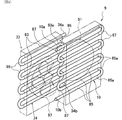
[図4]図1に示す実施形態で用いられる熱交換器および気液分離器を拡大して示す斜視図である。
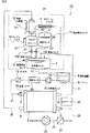
[図5]図1に示す実施形態の概略構成を示すブロック図である。
[図6]図1に示す実施形態の変形例を概略的に示す正面図である。
[図7]図1に示す実施形態の他の変形例を概略的に示す正面図である。
[図8](a)は燃料タンクおよび水溶液タンクならびにそれらの取り付け状態の概略構成を示す平面図、(b)はその長手側側面図、(c)は(a)におけるA−A矢視断面図である。
[図9]この発明の他の実施形態の概略構成を示すブロック図である。FIG. 1 is a perspective view schematically showing an embodiment of the present invention.
FIG. 2 is a front view schematically showing the embodiment shown in FIG.
FIG. 3 is a right side view schematically showing the embodiment shown in FIG.
4 is an enlarged perspective view showing a heat exchanger and a gas-liquid separator used in the embodiment shown in FIG.
FIG. 5 is a block diagram showing a schematic configuration of the embodiment shown in FIG.
FIG. 6 is a front view schematically showing a modification of the embodiment shown in FIG.
FIG. 7 is a front view schematically showing another modification of the embodiment shown in FIG.
[FIG. 8] (a) is a plan view showing a schematic configuration of a fuel tank and an aqueous solution tank and their attached state, (b) is a longitudinal side view thereof, and (c) is a cross-sectional view taken along line AA in (a). FIG.
FIG. 9 is a block diagram showing a schematic configuration of another embodiment of the present invention.
1,1A,1B,1C ダイレクトメタノール型燃料電池システム
3 燃料電池セルスタック
5,114 燃料タンク
7,116 水溶液タンク
9 熱交換器
10 熱交換パイプ
11,12,15,17,21,25,29,31,35,39,43,51,53,57,59 パイプ
13 水溶液ポンプ
23 エアポンプ
33 気液分離器
34 気液分離パイプ
37 水タンク
45,45b ドレインパイプ
49 水ポンプ
55 燃料ポンプ
81 コントローラ
105 キャップ
118 嵌め込み凸部
120 嵌め込み凹部
132,134 添加バルブ1, 1A, 1B, 1C Direct methanol
以下、図面を参照して、この発明の実施形態について説明する。
図1〜図5を参照して、この発明の一実施形態のダイレクトメタノール型燃料電池システム(以下、単に「燃料電池システム」という)1は、たとえば約400W〜500Wクラスの出力を有する据え置き型システムとして構成されており、略ボックス状(直方体状)の筐体Fを含む。Embodiments of the present invention will be described below with reference to the drawings.
1 to 5, a direct methanol fuel cell system (hereinafter simply referred to as “fuel cell system”) 1 according to an embodiment of the present invention is a stationary system having an output of, for example, about 400 W to 500 W class. And includes a substantially box-shaped (cuboid) housing F.
筐体F内には燃料電池セルスタック(以下、単に「セルスタック」という)3が固定されている。セルスタック3は、メタノールに基づく水素と酸素との電気化学反応により電気エネルギーを生成することができる単電池セルを複数個積層(スタック)して構成されている。燃料電池セルスタック3を構成する各単電池セルは、固体分子膜等から構成された電解質(電解質膜)と、この電解質を挟んで互いに対向する燃料極(アノード)および空気極(カソード)とを備えている。 A fuel cell stack (hereinafter simply referred to as “cell stack”) 3 is fixed in the housing F. The
筐体Fの上面ひいてはセルスタック3の上方側には燃料タンク5および水溶液タンク7が固定されている。燃料タンク5および水溶液タンク7は、ともに略直方体状に構成されており、ともにセルスタック3の長手方向(積層方向)に直交する方向(セルスタック3の短手方向)に沿って配置されている。燃料タンク5および水溶液タンク7は、それぞれの高さが略一致する位置に、セルスタック3の積層方向に並置されている。この実施形態では、燃料タンク5と水溶液タンク7とは、それぞれのタンク底面の高さが略一致するように配置されている。 A
燃料タンク5には、セルスタック3の上記電気化学反応の燃料となるメタノール燃料(高濃度(たとえば約50%)のメタノール水溶液)が貯蔵されており、水溶液タンク7には、燃料タンク5に貯蔵されたメタノール燃料をセルスタック3の電気化学反応に適した濃度(たとえば約3%)に希釈したメタノール水溶液が貯蔵されている。 The
また、セルスタック3の奥側(図3でいえばセルスタック3の右側)であり、かつ燃料タンク5および水溶液タンク7それぞれの一端部5aおよび7aの下側には、ラジエータからなる熱交換器9が設けられている。熱交換器9は、セルスタック3の積層方向に平行な状態で配置されている。水溶液タンク7と熱交換器9とはパイプ11によって接続されている。パイプ11の一端部は水溶液タンク7の下面に取り付けられるパイプ12に接続され、パイプ11の他端部は熱交換器9の熱交換パイプ10の上端部10aに接続されている。 Further, on the back side of the cell stack 3 (the right side of the
さらに、筐体F内の底部であってかつ水溶液タンク他端部7bの下方には水溶液ポンプ13が配置されている。水溶液ポンプ13と熱交換器9とはパイプ15によって接続されている。パイプ15の一端部は、熱交換器9の熱交換パイプ10の下端部10bに接続され、パイプ15は熱交換器側から水溶液ポンプ側に向かって斜め下方に延び、パイプ15の他端部は、水溶液ポンプ13の一側面13aに接続されている。 Further, an
水溶液ポンプ13にはパイプ17を介してフィルタ19が接続されている。フィルタ19は水溶液ポンプ13の上方に配置されている。パイプ17の一端部は、水溶液ポンプ13の一側面13aに平行な他側面13bに接続され、パイプ17は斜め上方に略U字状に屈曲して延び、パイプ17の他端部は、フィルタ19の下部に設けられている取り付けパイプ19aに接続されている。フィルタ19によってパイプ17を流れるメタノール水溶液内の不純物が取り除かれる。 A
また、水溶液ポンプ13およびフィルタ19間のパイプ17には、パイプ17を流れるメタノール水溶液の濃度を検出するための濃度センサ20が取り付けられている。 A
フィルタ19の上部に設けられている出力パイプ19bにはパイプ21が接続されている。パイプ21は、セルスタック3のうちフィルタ19に面する短手側の側面3bに沿って熱交換器側へ延出し、略90度屈曲してセルスタック3の長手側の側面3aに沿って延び、さらに側面3bに平行な短手側の側面3c側に廻り込み、セルスタック3の側面3cの下側一方角部近傍に形成された燃料入口部I1に接続されている。 A
さらに、セルスタック3の下方には、酸素を含む空気を供給するためエアポンプ23が配置されており、エアポンプ23にはパイプ25を介してフィルタ27が接続されている。フィルタ27はフィルタ19の隣りに配置されている。パイプ25の一端部は、エアポンプ23の水溶液ポンプ13側の側面下端部に設けられたポンプ出口部23aに接続され、パイプ25は上方に略U字状に屈曲して延び、パイプ25の他端部は、フィルタ27の下部に設けられている取り付けパイプ27aに接続されている。フィルタ27によってパイプ25を流れる空気内の不純物が取り除かれる。 Further, an
フィルタ27の上部に設けられている出力パイプ27bと、セルスタック3の側面3bの上側一方角部近傍に設けられた空気入口部I2とはパイプ29によって接続されている。 The
セルスタック3の側面3bの上側他方角部近傍の排ガス出口部I3と、水溶液タンク7の他端部7bとはパイプ31によって接続されている。 An exhaust gas outlet I3 in the vicinity of the upper other corner of the
一方、セルスタック3の側面3aと熱交換器9との間にはラジエータからなる気液分離器33が介挿されている。セルスタック3と気液分離器33とはパイプ35によって接続されている。パイプ35の一端部は、セルスタック3の側面3cの下側他方角部近傍の水出口部I4に接続され、パイプ35の他端部は気液分離器33の気液分離パイプ34の上端部34aに接続されている。 On the other hand, a gas-
そして、筐体F内の底部であってかつ熱交換器9および気液分離器33の下方には、セルスタック3の積層方向に沿って直方体状の水タンク37が配置されている。水タンク37と気液分離器33とはパイプ39によって接続されている。パイプ39の一端部は、水タンク37のタンク本体37aの上面に形成された水供給孔Hに接続され、パイプ39の他端部は、気液分離器33の気液分離パイプ34の下端部34bに接続されている。 A
水溶液タンク7の一端部7aと水タンク37のタンク本体37aとはパイプ43によって接続されており、パイプ43にはメタノールトラップ(冷却フィン)41が介挿されている。 One
水タンク37には、そのタンク本体37aに収容された水の一部および気体(排ガス)をそれぞれ排出するためのドレインパイプ45が取り付けられている。 The
さらに、水タンク37には水ポンプ49がパイプ51を介して接続されている。水ポンプ49と水溶液タンク7とはパイプ53を介して接続されている。 Further, a
そして、筐体F内の底部であってかつ燃料タンク5の下方には燃料ポンプ55が配置されている。 A
燃料ポンプ55と燃料タンク5とはパイプ57によって接続されている。パイプ57の一端部は燃料タンク5の下面に接続され、パイプ57は下方すなわち燃料ポンプ55に向かって延び、パイプ57の他端部はパイプ57に入口部55aを介して接続されている。 The
燃料ポンプ55の出口部55bにはパイプ59が接続され、パイプ59はパイプ57に沿って上方に延び、途中で水溶液タンク側へ屈曲して水溶液タンク7に接続されている。 A
一方、取り付けパイプ19aから分岐して下方に延びる分岐パイプ61は、パイプ15から分岐する分岐パイプ63にバルブ65を介して接続されている。 On the other hand, a
そして、燃料タンク5には液面検出センサ71が、水溶液タンク7には液面検出センサ73が、セルスタック3の燃料入口部I1付近には温度センサ75がそれぞれ取り付けられている。液面検出センサ71によって、燃料タンク5内のメタノール燃料S1の液面の高さが検出され、液面検出センサ73によって、水溶液タンク7内のメタノール水溶液S2の液面の高さが検出され、温度センサ75によって、燃料入口部I1を介して供給されるメタノール水溶液の温度が検出される。 A liquid
さらに、エアポンプ23を挟んで熱交換器9および気液分離器33に対向するようにコントローラ81が配置されている(図3参照)。コントローラ81は、濃度センサ20、液面検出センサ71、液面検出センサ73および温度センサ75に電気的に接続されている。コントローラ81は、基板上にマイクロプロセッサ等の電気回路部品を搭載して構成されている。 Furthermore, a
図4に示すように、熱交換器9の熱交換パイプ10は、たとえばステンレス等の金属材料を用いて溶接により形成されている。
すなわち、熱交換パイプ10は、垂直方向に間隔を空けて略平行に配列された複数の直線状パイプ部85と、複数の略U字状の継手パイプ部87とを含む。熱交換パイプ10として一端部10aから他端部10bまでの1本の連続したパイプを形成できるように、複数の直線状パイプ部85の隣接する端部85aが継手パイプ部87によって交互に接続されている。熱交換パイプ10に対向して冷却用のファン91が取り付けられている。As shown in FIG. 4, the
In other words, the
同様に、気液分離器33の気液分離パイプ34は、たとえばステンレス等の金属材料を用いて溶接により形成されている。
すなわち、気液分離パイプ34は、垂直方向に間隔を空けて略平行に配列された複数の直線状パイプ部93と、複数の略U字状の継手パイプ部95とを含む。気液分離パイプ34として一端部34aから他端部34bまでの1本の連続したパイプを形成できるように、複数の直線状パイプ部93の隣接する端部93aが継手パイプ部95によって交互に接続されている。気液分離パイプ34に対向して冷却用のファン97が取り付けられている。気液分離パイプ34は、セルスタック3から排出された水分を重力によって流下可能に構成される。Similarly, the gas-
That is, the gas-
熱交換器9および気液分離器33は、熱交換パイプ10の一部である継手パイプ部87と気液分離パイプ34の一部である継手パイプ部95とが互いに対向するように配置されている。 The
つぎに、燃料電池システム1における発電時の動作について説明する。
水溶液タンク7内の約3%の濃度に希釈されたメタノール水溶液は、水溶液ポンプ13の駆動によってパイプ11を介して熱交換器9内に流入し、熱交換パイプ10を流れる間にファン91によってセルスタック3に適した温度に冷却(熱交換)される。冷却されたメタノール水溶液は、パイプ15および17を流れ濃度センサ20を経由してフィルタ19に流入して不純物等が除去される。その後、パイプ21および燃料入口部I1を介してセルスタック3のアノード側にダイレクトに供給される。Next, the operation during power generation in the
The methanol aqueous solution diluted to a concentration of about 3% in the
一方、エアポンプ23から供給された空気は、パイプ25を介してフィルタ27に流入して不純物等が除去される。その後、パイプ29および空気入口部I2を介してセルスタック3のカソード側に供給される。 On the other hand, the air supplied from the
このとき、セルスタック3の各単電池セルにおけるアノード側では、供給されたメタノール水溶液におけるメタノールと水とが化学反応して二酸化炭素および水素イオンが生成され、生成された水素イオンは、電解質を介してカソード側に流入し、そのカソード側に供給された空気中の酸素と電気化学反応して水および電気エネルギーが生成される。生成された電気エネルギーは図示しない外部回路に供給される。 At this time, on the anode side of each unit cell of the
一方、各電池セルにおけるアノード側で生成された二酸化炭素(炭酸ガス)には、未反応のメタノール水蒸気が含まれており、この二酸化炭素は、セルスタック3の排ガス出口部I3およびパイプ31を介して水溶液タンク7に戻される。 On the other hand, carbon dioxide (carbon dioxide gas) generated on the anode side in each battery cell contains unreacted methanol water vapor, and this carbon dioxide passes through the exhaust gas outlet portion I3 of the
水溶液タンク7に戻された二酸化炭素は、パイプ43を経由して流れる。このとき、メタノール水蒸気は、メタノールトラップ41によって冷却されてメタノール水溶液として二酸化炭素から分離(トラップ)される。 The carbon dioxide returned to the
このようにしてパイプ43を流れる二酸化炭素およびメタノール水溶液は、水タンク37のタンク本体37aに流入し、メタノール水溶液は、タンク本体37aに回収され、二酸化炭素は、ドレインパイプ45を介して外部に排出される。 The carbon dioxide and the methanol aqueous solution flowing through the
一方、カソード側で生成された水(水蒸気)は、水出口部I4およびパイプ35を介して気液分離器33の気液分離パイプ34に流入し、気液分離パイプ34を流れる間にファン97によって冷却されて気液分離される。気液分離器33によって分離された気体成分および水成分は、パイプ39を介して水タンク37のタンク本体37aに流入し、当該気体成分はドレインパイプ45を介して排気される。 On the other hand, water (steam) generated on the cathode side flows into the gas-
そして、タンク本体37a内の回収された成分(水成分+メタノール水溶液)は、水ポンプ49の駆動によって水溶液タンク7に戻される。 Then, the recovered component (water component + methanol aqueous solution) in the
一方、コントローラ81は、濃度センサ20によって検出されたメタノール水溶液の濃度を表す濃度信号、液面検出センサ71および73によって検出されたそれぞれのタンク内のメタノール燃料およびメタノール水溶液の液面を表す液面検出信号、温度センサ75によって検出されたセルスタック3へダイレクトに供給されるメタノール水溶液の温度を表す信号、およびセルスタック3によって発電された電力(電流)の検出信号に基づいて、たとえば水ポンプ49の駆動制御および燃料ポンプ55の駆動制御をそれぞれ行う。 On the other hand, the
すなわち、コントローラ81は、水溶液タンク7内のメタノール水溶液の濃度が上記電気化学反応に適した濃度(約3%)よりも高い場合には、燃料ポンプ55の駆動を停止して水ポンプ49を駆動させて水タンク37の水を水溶液タンク7に供給することにより、水溶液タンク7のメタノール水溶液の濃度を上記電気化学反応に適した濃度に維持している。 That is, when the concentration of the aqueous methanol solution in the
また、水溶液タンク7内のメタノール水溶液の濃度が上記電気化学反応に適した濃度(約3%)よりも低い場合には、水ポンプ49の駆動を停止して燃料ポンプ55を駆動させ、燃料タンク5のメタノール燃料を水溶液タンク7に供給することにより、水溶液タンク7のメタノール水溶液の濃度を上記電気化学反応に適した濃度に維持している。この濃度制御によって、セルスタック3内においてメタノール水溶液内の未反応メタノールが電解質を透過してカソード側へ流入する、いわゆるクロスオーバを低く維持することができる。 Further, when the concentration of the aqueous methanol solution in the
このような燃料電池システム1によれば、重いセルスタック3の下方側に重いエアポンプ23を配置し、セルスタック3の上方側に燃料タンク5および水溶液タンク7を配置することによって、燃料電池システム1の重心を低くできる。したがって、燃料電池システム1の配置状態の安定性を上げることができ振動に対しても強くでき、また、燃料電池システム1に対して上方側から衝撃があった場合でも、燃料タンク5および水溶液タンク7により当該衝撃をブロックすることができ、燃料電池セルスタック1に対する影響を抑制することができる。さらに、燃料電池システム1を小型にでき体積効率を向上できる。 According to such a
また、燃料タンク5および水溶液タンク7を略同一の高さに並置することによって、燃料タンク5に収容されたメタノール燃料の液面高さと、水溶液タンク7に収容されたメタノール水溶液の液面高さとを略一致させることができる。したがって、燃料タンク5および水溶液タンク7の下方側に配置された燃料ポンプ55を駆動させて燃料タンク5から水溶液タンク7へメタノール燃料を供給する際に、各タンクの液面の差に起因する燃料ポンプ55の入口部55aと出口部55bとの間の圧力差を小さくすることができる。その結果、比較的小さな吐出性能を有する燃料ポンプ55を用いることができ、燃料ポンプ55を容易に設計・製作することができ、燃料電池システム全体の設計・製作コストを低減することができる。また、燃料ポンプ55を燃料タンク5の下方側に配置することによって、燃料タンク5から燃料ポンプ55へメタノール燃料を重力により容易に供給できる。ここでいう燃料タンク5と水溶液タンク7とが略同一の高さとは、水溶液タンク7の通常運転時の液面高さに対して燃料タンク5内のメタノール燃料の液面の高さが±10cm以内に収まるように両タンクがレイアウトされることをいい、好ましくは±5cm以内に設定される。 Further, the
さらに、水溶液タンク7から出力されたメタノール水溶液を熱交換してセルスタック側へ送る熱交換器9が燃料電池システム側方に配置されることによって、熱交換器9が外気に触れやすくなるので熱交換効率を向上させ、水溶液タンク7および燃料タンク5を上方に配置させることが可能となる。 Further, the
また、セルスタック3から排出された水分を気液分離する気液分離器33がセルスタック3と熱交換器9との間に介挿されるので、気液分離器33の稼働によって発生する冷却空気によってセルスタック3を冷却できる。 In addition, since a gas-
また、熱交換器9および気液分離器33は、熱交換器9の熱交換パイプ10の継手パイプ部87と気液分離機33の気液分離パイプ34の継手パイプ部95とが互いに対向するように配置されている。このため、熱交換器系(熱交換器9および気液分離器33)の設置スペースを、直線状パイプ部85および93に沿った方向において減少させることができ、その熱交換器系を含む燃料電池システム全体(筐体F)をコンパクトにすることができる。 Further, in the
さらに、熱交換器9および気液分離器33とコントローラ81とが、エアポンプ23を挟んで対向するように配置されるので、コントローラ81を熱交換器9および気液分離器33から離間させることができる。したがって、熱交換器9および気液分離器33の熱交換作用に起因して熱交換器9および気液分離器33に温度上昇が生じても、その温度上昇のコントローラ81に対する影響を、コントローラ81が熱交換器系(熱交換器9、気液分離器33)に隣接して配置されている場合と比べて軽減することができる。その結果、制御系であるコントローラ81の温度上昇を抑制することができる。 Furthermore, since the
また、セルスタック3の水出口部I4はパイプ35を介して気液分離器33の気液分離パイプ34の上端部34aに接続されているので、水蒸気から気液分離により得られた水を含む水分は重力によって容易に水タンク37側に出力することができる。 Moreover, since the water outlet part I4 of the
なお、図6に示す燃料電池システム1Aのように、ドレインパイプ45の排出側先端部に係合部(たとえば、雌螺子部)45aを形成し、係合部45aに係脱自在なキャップ105を取り付けてもよい。その他の構成については図2に示す燃料電池システム1と同様であるのでその重複する説明は省略する。 As in the
燃料電池システム1Aによれば、燃料電池システム1Aを長期間使用しない場合、キャップ105をドレインパイプ45の排出側先端部に装着すれば、ドレインパイプ45からの排水を阻止しつつ、少なくとも燃料電池セルスタック3の電解質膜が水没するまで水溶液タンク7の水位を上昇させておくことができ、電解質膜の乾燥を防止することができる。したがって、燃料電池システム1Aを長期間使用しない場合であっても、電解質膜の乾燥によるセルスタック3の性能劣化は生じない。 According to the
さらに、図7に示す燃料電池システム1Bのように、ドレインパイプ45に代えてドレインパイプ45bを用いてもよい。ドレインパイプ45bは伸縮自在かつその排出側先端部45b1を回動自在に構成されている。排出側先端部45b1を回動させかつドレインパイプ45bを伸張させることによって、水溶液タンク7のメタノール水溶液S2の液面の高さよりも高い位置に排出側先端部45b1を配置することができる。その他の構成については図2に示す燃料電池システム1と同様であるのでその重複する説明は省略する。 Further, a
燃料電池システム1Bによれば、ドレインパイプ45bからの排水を阻止しつつ、少なくともセルスタック3の電解質膜が水没するまで水溶液タンク7の水位を上昇させることができる。したがって、燃料電池システム1Bを長期間使用しない場合であっも、電解質膜の乾燥によるセルスタック3の性能劣化は生じない。 According to the
ついで、図8(a)〜(c)を参照して、燃料電池システム1に用いられる燃料タンクおよび水溶液タンクの変形例について説明する。
燃料タンク114および水溶液タンク116は、直方体状のフレーム117に一体的に取り付けられており、図1に示したように、たとえばセルスタック3の上方に配置されている。Next, modified examples of the fuel tank and the aqueous solution tank used in the
The
すなわち、燃料タンク114および水溶液タンク116は、たとえばPE(ポリエチレン)ブロー成型によって2つの部屋(中空体)構造として一体的に成形されている。
燃料タンク114は、平面視および長手側の一側面視でそれぞれ略矩形状を成す中空体である。水溶液タンク116は、略直方体形状から上記矩形状の燃料タンク114を切り欠いた際の残部に対応する形状を有する中空体である。That is, the
The
燃料タンク114および水溶液タンク116それぞれの対向面は互いに略一致した形状を成しており、その一方の対向面(たとえば、水溶液タンク116の対向面)から他方の対向面(たとえば、燃料タンク114の対向面)に向かって複数(たとえば3個)の嵌め込み凸部118が突出されている。 The opposing surfaces of the
このとき、燃料タンク114の対向面における嵌め込み凸部118に対応する位置には、嵌め込み凸部118が嵌入される複数(3個)の嵌め込み凹部120が形成されている。嵌め込み凸部118の嵌め込み凹部120への嵌入によって、水溶液タンク116は燃料タンク114に対向しかつ離間した状態に配置される。 At this time, a plurality of (three) fitting
燃料タンク114および水溶液タンク116の対向面間には、断熱材121が充填されている。
燃料タンク114には、メタノール燃料(略50%の高濃度メタノール水溶液)を排出するための出口部122が形成されており、当該出口部122にはパイプ57が接続される。A space between the opposing surfaces of the
The
また、水溶液タンク116の上面には、メタノール燃料が供給されるための入口部124が形成され、当該入口部124にはパイプ59が接続される。さらに、水溶液タンク116の上面には、水が供給されるための入口部126が形成、当該入口部126にはパイプ53が接続される。 An
そして、水溶液タンク116のたとえば下面には、メタノール水溶液を排出するための出口部128が形成され、当該出口部128にはパイプ11が接続される。さらに、水溶液タンク116の短手側の一側面には、反応後の二酸化炭素(未反応のメタノール水蒸気が含まれている)が供給されるための入口部130が形成され、当該入口部130にはパイプ31が接続される。 An
そして、水溶液タンク116の上面には、入口部130を介して供給された二酸化炭素を水タンク側へ排出するための出口部131が設けられており、当該出口部131は、パイプ43を介して水タンク37に接続されている。 The upper surface of the
このように燃料タンク114および水溶液タンク116を一体化して一体型タンクとすることによって、上述の実施形態と比べて、部品点数を削減することができ、燃料電池システムを小さくできる。 Thus, by integrating the
また、燃料タンク114および水溶液タンク116間に断熱材121を充填しているため、一方の温度変動の他方への影響を抑制することができる。 Moreover, since the
さらに、図9を参照して、この発明の他の実施形態の燃料電池システム1Cについて説明する。
燃料電池システム1Cは、燃料電池システム1とは異なるレイアウト構造を有している。Furthermore, referring to FIG. 9, a fuel cell system 1C according to another embodiment of the present invention will be described.
The fuel cell system 1C has a layout structure different from that of the
すなわち、図9に示すように、燃料電池システム1Cでは、燃料タンク5、水タンク37および気液分離器33が水溶液タンク7より上方に配置されてユニットU1が構成される。水溶液タンク7の下方にセルスタック3が配置されている。パイプ35は、セルスタック3の水出口部I4から気液分離器33の上方側まで上方に立ち上がり、逆U字状に折曲して気液分離器33の気液分離パイプ34の上端部34aに接続されている。そして、水タンク37および水溶液タンク7間を接続するパイプ51の途中に、上述した燃料電池システム1の水ポンプ49に代えて、開閉自在な添加バルブ132が介挿されている。さらに、燃料タンク5および水溶液タンク7間を接続するパイプ57の途中に、燃料電池システム1の燃料ポンプ55に代えて、開閉自在な添加バルブ134が介挿されている。 That is, as shown in FIG. 9, in the fuel cell system 1C, the
なお、その他の構成、レイアウトおよび発電動作については、燃料電池システム1と同様であるため、その説明は省略する。 Other configurations, layouts, and power generation operations are the same as those of the
燃料電池システム1Cによれば、燃料タンク5、水タンク37および気液分離器33を水溶液タンク7の上方に配置したため、重力を利用することにより、燃料ポンプではなくコントローラ81による添加バルブ132および134の開閉制御によって、燃料タンク5および水タンク37からそれぞれメタノール燃料および水を水溶液タンク7に供給することができる。その結果、ポンプよりも安価な添加バルブを利用することができ、燃料電池システム1C全体のコストを低減することができる。 According to the fuel cell system 1C, since the
特に、この構成によれば、セルスタック3の上方に気液分離器33を配置したため、気液分離器33で液化された水分を円滑に水タンク37へ導くことができる。 In particular, according to this configuration, since the gas-
また、水溶液タンク7とセルスタック3とを近接して配置することができるため、メタノール水溶液循環系の圧力損失を小さくすることができる。 Moreover, since the
この発明が詳細に説明され図示されたが、それは単なる図解および一例として用いたものであり、限定であると解されるべきではないことは明らかであり、この発明の精神および範囲は添付された請求の範囲の文言のみによって限定される。 Although the present invention has been described and illustrated in detail, it is clear that it has been used merely as an illustration and example and should not be construed as limiting, and the spirit and scope of the present invention are attached Limited only by the language of the claims.
Claims (10)
前記水溶液タンクに供給すべきメタノール燃料を収容する燃料タンク、
前記水溶液タンクからのメタノール水溶液が供給され電気化学反応によって電気エネルギーを生成する燃料電池セルスタック、
前記燃料タンクから下方に延びる第1パイプ、
前記水溶液タンクから下方に延びる第2パイプ、ならびに
前記燃料タンクおよび前記水溶液タンクの下方側に配置され、かつ前記第1パイプを介して前記燃料タンクに前記第2パイプを介して前記水溶液タンクにそれぞれ接続される燃料ポンプを備え、
前記燃料タンクおよび前記水溶液タンクが前記燃料電池セルスタックに対して上方側に配置され、
前記燃料タンクおよび前記水溶液タンクが略同一の高さに並置され、
前記燃料ポンプは、前記燃料タンクから前記第1パイプを介して与えられたメタノール燃料を圧送して前記第2パイプを介して前記水溶液タンクに供給する、ダイレクトメタノール型燃料電池システム。An aqueous solution tank containing an aqueous methanol solution,
A fuel tank for storing methanol fuel to be supplied to the aqueous solution tank ;
Fuel cell stack aqueous methanol solution from the previous SL aqueous solution tank to generate electrical energy through an electrochemical reaction is supplied,
A first pipe extending downward from the fuel tank;
A second pipe extending downward from the aqueous solution tank; and
A fuel pump disposed below the fuel tank and the aqueous solution tank and connected to the fuel tank via the first pipe and connected to the aqueous solution tank via the second pipe ;
Is pre Symbol fuel tank and the aqueous solution tank is disposed on the upper side relative to the fuel cell stack,
The fuel tank and the aqueous solution tank are juxtaposed at substantially the same height,
The fuel pump is a direct methanol fuel cell system in which methanol fuel supplied from the fuel tank via the first pipe is pumped and supplied to the aqueous solution tank via the second pipe .
前記熱交換器が当該燃料電池システム側方に配置される、請求項1に記載のダイレクトメタノール型燃料電池システム。A heat exchanger for exchanging heat of the aqueous methanol solution output from the aqueous solution tank and sending it to the fuel cell stack side;
The direct methanol fuel cell system according to claim 1, wherein the heat exchanger is disposed on a side of the fuel cell system.
当該気液分離によって得られた水を収容する水タンクをさらに含み、
前記気液分離器が前記燃料電池セルスタックと前記熱交換器との間に介挿される、請求項3に記載のダイレクトメタノール型燃料電池システム。A gas-liquid separator that gas-liquid separates the water discharged from the fuel cell stack, and a water tank that stores water obtained by the gas-liquid separation,
The direct methanol fuel cell system according to claim 3 , wherein the gas-liquid separator is interposed between the fuel cell stack and the heat exchanger.
前記気液分離器は、前記燃料電池セルスタックから排出された水分を案内して前記水タンクへ出力する気液分離パイプを有し、
前記熱交換パイプおよび前記気液分離パイプのそれぞれの少なくとも一部が相互に対向するように前記気液分離器が配置される、請求項4に記載のダイレクトメタノール型燃料電池システム。The heat exchanger has a heat exchange pipe that guides the methanol aqueous solution output from the aqueous solution tank and outputs it to the fuel cell stack side,
The gas-liquid separator has a gas-liquid separation pipe that guides the moisture discharged from the fuel cell stack and outputs it to the water tank,
The direct methanol fuel cell system according to claim 4 , wherein the gas-liquid separator is arranged so that at least a part of each of the heat exchange pipe and the gas-liquid separation pipe is opposed to each other.
前記エアポンプの一側方に配置され前記水溶液タンクから前記燃料電池セルスタックへ出力されるメタノール水溶液の濃度を制御するコントローラをさらに含み、
前記熱交換器および前記気液分離器と前記コントローラとが、前記エアポンプを挟んで対向するように配置される、請求項4に記載のダイレクトメタノール型燃料電池システム。An air pump disposed below the fuel cell stack and supplying oxygen-containing air to the fuel cell stack; and disposed on one side of the air pump and output from the aqueous solution tank to the fuel cell stack. A controller for controlling the concentration of the aqueous methanol solution,
The direct methanol fuel cell system according to claim 4 , wherein the heat exchanger, the gas-liquid separator, and the controller are arranged so as to face each other with the air pump interposed therebetween.
前記水溶液タンクはその側面に前記第1嵌合部に嵌合すべき第2嵌合部を有する、請求項1に記載のダイレクトメタノール型燃料電池システム。The fuel tank has a first fitting portion on its side surface,
The direct methanol fuel cell system according to claim 1 , wherein the aqueous solution tank has a second fitting portion to be fitted to the first fitting portion on a side surface thereof.
前記ドレインパイプの排出側先端部に着脱自在に設けられる排水阻止用のキャップをさらに含む、請求項4に記載のダイレクトメタノール型燃料電池システム。Further comprising the water connected thereto drain pipe in the tank and the drain pipe cap for removably provided is drained blocking of the discharge side tip of, for discharging water in the water tank, according to claim 4 Direct methanol fuel cell system.
前記ドレインパイプの排出側先端部を前記燃料電池セルスタック上面よりも高い位置に配置できるように、前記ドレインパイプは伸縮自在にかつその排出側先端部を回動自在に構成される、請求項4に記載のダイレクトメタノール型燃料電池システム。Further comprising a drain pipe connected to the water tank for discharging water in the water tank;
Wherein such a discharge side tip of the drain pipe can be disposed at a position higher than the fuel cell stack upper surface, the drain pipe is telescopically and configured the discharge side tip rotatably claim 4 The direct methanol fuel cell system described in 1.
Applications Claiming Priority (5)
| Application Number | Priority Date | Filing Date | Title |
|---|---|---|---|
| JP2003270208 | 2003-07-01 | ||
| JP2003270208 | 2003-07-01 | ||
| JP2003406032 | 2003-12-04 | ||
| JP2003406032 | 2003-12-04 | ||
| PCT/JP2004/008893 WO2005004267A1 (en) | 2003-07-01 | 2004-06-24 | Direct methanol fuel cell system |
Publications (2)
| Publication Number | Publication Date |
|---|---|
| JPWO2005004267A1 JPWO2005004267A1 (en) | 2006-08-17 |
| JP4585449B2 true JP4585449B2 (en) | 2010-11-24 |
Family
ID=33566801
Family Applications (1)
| Application Number | Title | Priority Date | Filing Date |
|---|---|---|---|
| JP2005511326A Expired - Fee Related JP4585449B2 (en) | 2003-07-01 | 2004-06-24 | Direct methanol fuel cell system |
Country Status (5)
| Country | Link |
|---|---|
| US (1) | US20060222923A1 (en) |
| EP (1) | EP1575110A4 (en) |
| JP (1) | JP4585449B2 (en) |
| TW (1) | TW200503313A (en) |
| WO (1) | WO2005004267A1 (en) |
Families Citing this family (22)
| Publication number | Priority date | Publication date | Assignee | Title |
|---|---|---|---|---|
| JP2006059624A (en) * | 2004-08-19 | 2006-03-02 | Fujitsu Ltd | Circulation type liquid fuel cell |
| JP4646117B2 (en) * | 2005-02-22 | 2011-03-09 | ヤマハ発動機株式会社 | Fuel cell system and transportation equipment using the same |
| JP2007042541A (en) * | 2005-08-05 | 2007-02-15 | Yamaha Motor Co Ltd | Fuel cell system and water replenishing method in it |
| US7833672B2 (en) * | 2006-09-08 | 2010-11-16 | Samsung Sdi Co., Ltd. | Modular direct fuel cell system with integrated processor |
| KR100784017B1 (en) * | 2006-11-20 | 2007-12-07 | 삼성에스디아이 주식회사 | Non-reactive fuel recycling device and fuel cell system possessing it |
| TW200830073A (en) * | 2007-01-10 | 2008-07-16 | Syspotek Corp | Liquid concentration control and supply apparatus |
| US8551667B2 (en) | 2007-04-17 | 2013-10-08 | Ini Power Systems, Inc. | Hydrogel barrier for fuel cells |
| KR101473318B1 (en) * | 2007-09-28 | 2014-12-17 | 삼성에스디아이 주식회사 | Recycler for direct methanol fuel cell and managing method thereof |
| EP2211411A4 (en) * | 2007-10-11 | 2011-11-16 | Panasonic Corp | Fuel cell system |
| TW200917559A (en) * | 2007-10-15 | 2009-04-16 | Nan Ya Printed Circuit Board Corp | Fuel cell system |
| JP5245393B2 (en) * | 2007-12-25 | 2013-07-24 | トヨタ紡織株式会社 | Gas-liquid separator for fuel cell system |
| JP5312830B2 (en) * | 2008-03-24 | 2013-10-09 | ダイハツ工業株式会社 | Fuel cell and fuel cell vehicle |
| JP2010092775A (en) * | 2008-10-09 | 2010-04-22 | Yamaha Motor Co Ltd | Fuel cell system |
| WO2011004606A1 (en) | 2009-07-08 | 2011-01-13 | パナソニック株式会社 | Fuel cell system |
| US8783304B2 (en) | 2010-12-03 | 2014-07-22 | Ini Power Systems, Inc. | Liquid containers and apparatus for use with power producing devices |
| US9065095B2 (en) * | 2011-01-05 | 2015-06-23 | Ini Power Systems, Inc. | Method and apparatus for enhancing power density of direct liquid fuel cells |
| JP6140603B2 (en) * | 2013-12-25 | 2017-05-31 | 京セラ株式会社 | Fuel cell device |
| CN106299382B (en) * | 2015-05-28 | 2018-11-09 | 清华大学 | Fuel cell system |
| CN106299430B (en) * | 2015-05-28 | 2018-10-02 | 清华大学 | The application method of fuel cell |
| CN106299383B (en) * | 2015-05-28 | 2018-11-30 | 清华大学 | Fuel cell mould group |
| US10581097B2 (en) * | 2018-01-16 | 2020-03-03 | Toyota Motor Engineering & Manufacturing North America, Inc. | Operating fuel cell vehicles during inclination events |
| CN110380095A (en) * | 2018-04-12 | 2019-10-25 | 武汉众宇动力系统科技有限公司 | Integrated fuel cell electricity generation system and device and its configuration method |
Family Cites Families (15)
| Publication number | Priority date | Publication date | Assignee | Title |
|---|---|---|---|---|
| EP0181569B1 (en) * | 1984-10-31 | 1991-05-02 | Hitachi, Ltd. | Liquid fuel cell |
| JPS635506U (en) * | 1986-06-23 | 1988-01-14 | ||
| US6703150B2 (en) * | 1993-10-12 | 2004-03-09 | California Institute Of Technology | Direct methanol feed fuel cell and system |
| US5599638A (en) * | 1993-10-12 | 1997-02-04 | California Institute Of Technology | Aqueous liquid feed organic fuel cell using solid polymer electrolyte membrane |
| US5773162A (en) * | 1993-10-12 | 1998-06-30 | California Institute Of Technology | Direct methanol feed fuel cell and system |
| US6564823B1 (en) * | 1996-12-30 | 2003-05-20 | John M. Mankins | Method and apparatus for testing plumbing installations |
| CA2290302A1 (en) * | 1999-11-23 | 2001-05-23 | Karl Kordesch | Direct methanol fuel cell with circulating electrolyte |
| DE10004800A1 (en) * | 2000-02-03 | 2001-08-09 | Opel Adam Ag | Fuel cell system |
| US6696189B2 (en) * | 2000-12-15 | 2004-02-24 | Motorola, Inc. | Direct methanol fuel cell system including an integrated methanol sensor and method of fabrication |
| US6558833B2 (en) * | 2000-12-18 | 2003-05-06 | Mccoy Reginald F.H. | Recharging batteries by electrolyte transfer |
| US6686081B2 (en) * | 2001-05-15 | 2004-02-03 | Mti Microfuel Cells, Inc. | Methods and apparatuses for a pressure driven fuel cell system |
| US6670879B2 (en) * | 2001-07-27 | 2003-12-30 | Edward Carter | Transformer container |
| JP2003132924A (en) * | 2001-10-30 | 2003-05-09 | Yuasa Corp | Fuel cell system directly feeding methanol |
| JP2003208910A (en) * | 2002-01-11 | 2003-07-25 | Yuasa Corp | Liquid-fuel direct supply type fuel cell system |
| JP3742385B2 (en) * | 2002-12-26 | 2006-02-01 | 株式会社東芝 | DIRECT Methanol FUEL CELL SYSTEM, PORTABLE ELECTRONIC DEVICE, AND METHOD FOR DETECTING LIQUID FUEL FUEL OF DIRECT Methanol FUEL CELL SYSTEM |
-
2004
- 2004-06-24 US US10/539,000 patent/US20060222923A1/en not_active Abandoned
- 2004-06-24 EP EP04746362A patent/EP1575110A4/en active Pending
- 2004-06-24 WO PCT/JP2004/008893 patent/WO2005004267A1/en active Application Filing
- 2004-06-24 JP JP2005511326A patent/JP4585449B2/en not_active Expired - Fee Related
- 2004-06-30 TW TW093119560A patent/TW200503313A/en unknown
Also Published As
| Publication number | Publication date |
|---|---|
| US20060222923A1 (en) | 2006-10-05 |
| TW200503313A (en) | 2005-01-16 |
| JPWO2005004267A1 (en) | 2006-08-17 |
| EP1575110A4 (en) | 2008-09-24 |
| EP1575110A1 (en) | 2005-09-14 |
| WO2005004267A1 (en) | 2005-01-13 |
Similar Documents
| Publication | Publication Date | Title |
|---|---|---|
| JP4585449B2 (en) | Direct methanol fuel cell system | |
| JP4152360B2 (en) | Fuel cell system | |
| US8808939B2 (en) | Fuel cell stack and fuel cell cogeneration system including the same | |
| JP2011171283A (en) | Fuel cell system | |
| WO2005050769A2 (en) | Fuel cell system and transporting equipment including the same | |
| JP4588567B2 (en) | Fuel cell stack and fuel cell system including the same | |
| WO2018092432A1 (en) | Fuel cell | |
| JP5312830B2 (en) | Fuel cell and fuel cell vehicle | |
| US7767326B2 (en) | Water controller system having stable structure for direct methanol fuel cell | |
| JP4712007B2 (en) | Fuel cell system | |
| JP4550491B2 (en) | Fuel cell system and transportation equipment using the same | |
| JP2011150940A (en) | Fuel cell system | |
| JP2009181701A (en) | Fuel battery device | |
| JP5430318B2 (en) | Fuel cell stack | |
| JP2007227014A (en) | Fuel cell system | |
| JP2005327540A (en) | Fuel cell system and transport equipment using the same | |
| JP2006114261A (en) | Fuel cell system and transport equipment using the same | |
| JP2006086111A (en) | Fuel cell system and its control method | |
| JP2005150106A (en) | Fuel cell system and transport equipment using above | |
| JP2006147217A (en) | Fuel cell system | |
| JP5486857B2 (en) | Fuel cell system | |
| JP2012074294A (en) | Fuel cell system for vehicle | |
| JP2006073312A (en) | Fuel cell generator | |
| JP2008027804A (en) | Fuel cell | |
| JP5504077B2 (en) | Fuel cell stack |
Legal Events
| Date | Code | Title | Description |
|---|---|---|---|
| A621 | Written request for application examination |
Free format text: JAPANESE INTERMEDIATE CODE: A621 Effective date: 20060825 |
|
| A131 | Notification of reasons for refusal |
Free format text: JAPANESE INTERMEDIATE CODE: A131 Effective date: 20100601 |
|
| A521 | Written amendment |
Free format text: JAPANESE INTERMEDIATE CODE: A523 Effective date: 20100727 |
|
| TRDD | Decision of grant or rejection written | ||
| A01 | Written decision to grant a patent or to grant a registration (utility model) |
Free format text: JAPANESE INTERMEDIATE CODE: A01 Effective date: 20100831 |
|
| A01 | Written decision to grant a patent or to grant a registration (utility model) |
Free format text: JAPANESE INTERMEDIATE CODE: A01 |
|
| A61 | First payment of annual fees (during grant procedure) |
Free format text: JAPANESE INTERMEDIATE CODE: A61 Effective date: 20100903 |
|
| R150 | Certificate of patent or registration of utility model |
Ref document number: 4585449 Country of ref document: JP Free format text: JAPANESE INTERMEDIATE CODE: R150 Free format text: JAPANESE INTERMEDIATE CODE: R150 |
|
| FPAY | Renewal fee payment (event date is renewal date of database) |
Free format text: PAYMENT UNTIL: 20130910 Year of fee payment: 3 |
|
| R250 | Receipt of annual fees |
Free format text: JAPANESE INTERMEDIATE CODE: R250 |
|
| R250 | Receipt of annual fees |
Free format text: JAPANESE INTERMEDIATE CODE: R250 |
|
| R250 | Receipt of annual fees |
Free format text: JAPANESE INTERMEDIATE CODE: R250 |
|
| R250 | Receipt of annual fees |
Free format text: JAPANESE INTERMEDIATE CODE: R250 |
|
| R250 | Receipt of annual fees |
Free format text: JAPANESE INTERMEDIATE CODE: R250 |
|
| R250 | Receipt of annual fees |
Free format text: JAPANESE INTERMEDIATE CODE: R250 |
|
| LAPS | Cancellation because of no payment of annual fees |