JP4585310B2 - Membrane electrochemical cell stack - Google Patents
Membrane electrochemical cell stack Download PDFInfo
- Publication number
- JP4585310B2 JP4585310B2 JP2004500351A JP2004500351A JP4585310B2 JP 4585310 B2 JP4585310 B2 JP 4585310B2 JP 2004500351 A JP2004500351 A JP 2004500351A JP 2004500351 A JP2004500351 A JP 2004500351A JP 4585310 B2 JP4585310 B2 JP 4585310B2
- Authority
- JP
- Japan
- Prior art keywords
- fuel cell
- cassette
- sealant
- electrochemical
- flow field
- Prior art date
- Legal status (The legal status is an assumption and is not a legal conclusion. Google has not performed a legal analysis and makes no representation as to the accuracy of the status listed.)
- Expired - Lifetime
Links
Images


Classifications
-
- H—ELECTRICITY
- H01—ELECTRIC ELEMENTS
- H01M—PROCESSES OR MEANS, e.g. BATTERIES, FOR THE DIRECT CONVERSION OF CHEMICAL ENERGY INTO ELECTRICAL ENERGY
- H01M8/00—Fuel cells; Manufacture thereof
- H01M8/02—Details
- H01M8/0271—Sealing or supporting means around electrodes, matrices or membranes
- H01M8/028—Sealing means characterised by their material
- H01M8/0284—Organic resins; Organic polymers
-
- H—ELECTRICITY
- H01—ELECTRIC ELEMENTS
- H01M—PROCESSES OR MEANS, e.g. BATTERIES, FOR THE DIRECT CONVERSION OF CHEMICAL ENERGY INTO ELECTRICAL ENERGY
- H01M8/00—Fuel cells; Manufacture thereof
- H01M8/02—Details
- H01M8/0271—Sealing or supporting means around electrodes, matrices or membranes
-
- H—ELECTRICITY
- H01—ELECTRIC ELEMENTS
- H01M—PROCESSES OR MEANS, e.g. BATTERIES, FOR THE DIRECT CONVERSION OF CHEMICAL ENERGY INTO ELECTRICAL ENERGY
- H01M8/00—Fuel cells; Manufacture thereof
- H01M8/02—Details
- H01M8/0202—Collectors; Separators, e.g. bipolar separators; Interconnectors
-
- H—ELECTRICITY
- H01—ELECTRIC ELEMENTS
- H01M—PROCESSES OR MEANS, e.g. BATTERIES, FOR THE DIRECT CONVERSION OF CHEMICAL ENERGY INTO ELECTRICAL ENERGY
- H01M8/00—Fuel cells; Manufacture thereof
- H01M8/02—Details
- H01M8/0202—Collectors; Separators, e.g. bipolar separators; Interconnectors
- H01M8/0247—Collectors; Separators, e.g. bipolar separators; Interconnectors characterised by the form
-
- H—ELECTRICITY
- H01—ELECTRIC ELEMENTS
- H01M—PROCESSES OR MEANS, e.g. BATTERIES, FOR THE DIRECT CONVERSION OF CHEMICAL ENERGY INTO ELECTRICAL ENERGY
- H01M8/00—Fuel cells; Manufacture thereof
- H01M8/02—Details
- H01M8/0202—Collectors; Separators, e.g. bipolar separators; Interconnectors
- H01M8/0258—Collectors; Separators, e.g. bipolar separators; Interconnectors characterised by the configuration of channels, e.g. by the flow field of the reactant or coolant
- H01M8/026—Collectors; Separators, e.g. bipolar separators; Interconnectors characterised by the configuration of channels, e.g. by the flow field of the reactant or coolant characterised by grooves, e.g. their pitch or depth
-
- H—ELECTRICITY
- H01—ELECTRIC ELEMENTS
- H01M—PROCESSES OR MEANS, e.g. BATTERIES, FOR THE DIRECT CONVERSION OF CHEMICAL ENERGY INTO ELECTRICAL ENERGY
- H01M8/00—Fuel cells; Manufacture thereof
- H01M8/02—Details
- H01M8/0202—Collectors; Separators, e.g. bipolar separators; Interconnectors
- H01M8/0267—Collectors; Separators, e.g. bipolar separators; Interconnectors having heating or cooling means, e.g. heaters or coolant flow channels
-
- H—ELECTRICITY
- H01—ELECTRIC ELEMENTS
- H01M—PROCESSES OR MEANS, e.g. BATTERIES, FOR THE DIRECT CONVERSION OF CHEMICAL ENERGY INTO ELECTRICAL ENERGY
- H01M8/00—Fuel cells; Manufacture thereof
- H01M8/02—Details
- H01M8/0271—Sealing or supporting means around electrodes, matrices or membranes
- H01M8/0273—Sealing or supporting means around electrodes, matrices or membranes with sealing or supporting means in the form of a frame
-
- H—ELECTRICITY
- H01—ELECTRIC ELEMENTS
- H01M—PROCESSES OR MEANS, e.g. BATTERIES, FOR THE DIRECT CONVERSION OF CHEMICAL ENERGY INTO ELECTRICAL ENERGY
- H01M8/00—Fuel cells; Manufacture thereof
- H01M8/04—Auxiliary arrangements, e.g. for control of pressure or for circulation of fluids
- H01M8/04082—Arrangements for control of reactant parameters, e.g. pressure or concentration
- H01M8/04089—Arrangements for control of reactant parameters, e.g. pressure or concentration of gaseous reactants
-
- H—ELECTRICITY
- H01—ELECTRIC ELEMENTS
- H01M—PROCESSES OR MEANS, e.g. BATTERIES, FOR THE DIRECT CONVERSION OF CHEMICAL ENERGY INTO ELECTRICAL ENERGY
- H01M8/00—Fuel cells; Manufacture thereof
- H01M8/10—Fuel cells with solid electrolytes
- H01M8/1004—Fuel cells with solid electrolytes characterised by membrane-electrode assemblies [MEA]
-
- H—ELECTRICITY
- H01—ELECTRIC ELEMENTS
- H01M—PROCESSES OR MEANS, e.g. BATTERIES, FOR THE DIRECT CONVERSION OF CHEMICAL ENERGY INTO ELECTRICAL ENERGY
- H01M8/00—Fuel cells; Manufacture thereof
- H01M8/24—Grouping of fuel cells, e.g. stacking of fuel cells
- H01M8/241—Grouping of fuel cells, e.g. stacking of fuel cells with solid or matrix-supported electrolytes
-
- H—ELECTRICITY
- H01—ELECTRIC ELEMENTS
- H01M—PROCESSES OR MEANS, e.g. BATTERIES, FOR THE DIRECT CONVERSION OF CHEMICAL ENERGY INTO ELECTRICAL ENERGY
- H01M8/00—Fuel cells; Manufacture thereof
- H01M8/24—Grouping of fuel cells, e.g. stacking of fuel cells
- H01M8/2465—Details of groupings of fuel cells
- H01M8/2483—Details of groupings of fuel cells characterised by internal manifolds
-
- H—ELECTRICITY
- H01—ELECTRIC ELEMENTS
- H01M—PROCESSES OR MEANS, e.g. BATTERIES, FOR THE DIRECT CONVERSION OF CHEMICAL ENERGY INTO ELECTRICAL ENERGY
- H01M8/00—Fuel cells; Manufacture thereof
- H01M8/24—Grouping of fuel cells, e.g. stacking of fuel cells
- H01M8/2465—Details of groupings of fuel cells
- H01M8/2484—Details of groupings of fuel cells characterised by external manifolds
- H01M8/2485—Arrangements for sealing external manifolds; Arrangements for mounting external manifolds around a stack
-
- H—ELECTRICITY
- H01—ELECTRIC ELEMENTS
- H01M—PROCESSES OR MEANS, e.g. BATTERIES, FOR THE DIRECT CONVERSION OF CHEMICAL ENERGY INTO ELECTRICAL ENERGY
- H01M8/00—Fuel cells; Manufacture thereof
- H01M8/10—Fuel cells with solid electrolytes
- H01M2008/1095—Fuel cells with polymeric electrolytes
-
- H—ELECTRICITY
- H01—ELECTRIC ELEMENTS
- H01M—PROCESSES OR MEANS, e.g. BATTERIES, FOR THE DIRECT CONVERSION OF CHEMICAL ENERGY INTO ELECTRICAL ENERGY
- H01M8/00—Fuel cells; Manufacture thereof
- H01M8/24—Grouping of fuel cells, e.g. stacking of fuel cells
- H01M8/2465—Details of groupings of fuel cells
- H01M8/247—Arrangements for tightening a stack, for accommodation of a stack in a tank or for assembling different tanks
- H01M8/248—Means for compression of the fuel cell stacks
-
- Y—GENERAL TAGGING OF NEW TECHNOLOGICAL DEVELOPMENTS; GENERAL TAGGING OF CROSS-SECTIONAL TECHNOLOGIES SPANNING OVER SEVERAL SECTIONS OF THE IPC; TECHNICAL SUBJECTS COVERED BY FORMER USPC CROSS-REFERENCE ART COLLECTIONS [XRACs] AND DIGESTS
- Y02—TECHNOLOGIES OR APPLICATIONS FOR MITIGATION OR ADAPTATION AGAINST CLIMATE CHANGE
- Y02E—REDUCTION OF GREENHOUSE GAS [GHG] EMISSIONS, RELATED TO ENERGY GENERATION, TRANSMISSION OR DISTRIBUTION
- Y02E60/00—Enabling technologies; Technologies with a potential or indirect contribution to GHG emissions mitigation
- Y02E60/30—Hydrogen technology
- Y02E60/50—Fuel cells
Abstract
Description
本発明は、2002年4月23日付出願の米国特許仮出願第60/374,631号の権利を主張するものであり、参照によりその全文を本願に組み入れてある。 This invention claims the benefit of US Provisional Application No. 60 / 374,631, filed Apr. 23, 2002, which is hereby incorporated by reference in its entirety.
発明の分野
本発明は、膜式電気化学的電池(Membrane based electrochemical cells)に関し、より具体的には、陽子交換膜(PEM(proton exchange membrane))燃料電池スタックに関する。本発明は、これらのPEM燃料電池スタックの新規な製造方法についても記述する。
FIELD OF THE INVENTION This invention relates to membrane based electrochemical cells, and more specifically to proton exchange membrane (PEM) fuel cell stacks. The present invention also describes novel methods for manufacturing these PEM fuel cell stacks.
発明の背景
膜方式電気化学的電池、特に陽子交換膜(PEM)燃料電池は、よく知られている。PEM燃料電池は、実質的に環境排出物なしに化学エネルギーを電力に変換するとともに、エネルギーが貯蔵されるのではなく、供給燃料から抽出される点においてバッテリーとは異なる。したがって、燃料電池は、充電/放電サイクルに拘束されず、燃料が連続的に供給される限り、所定の電力出力を維持することができる。燃料電池研究と実用化への巨額の投資は、この技術が市場において相当な可能性を有することを示すものである。しかしながら、従来型発電技術と比較しての燃料電池のコストが高いことが、その普及を遅らせている。燃料電池の製造および組立のコストは、それに含まれる材料および労力のために、高くなる可能性がある。実際に、燃料電池のコストの85%までが、製造によるものとなる可能性がある。
BACKGROUND OF THE INVENTION Membrane-type electrochemical cells, particularly proton exchange membrane (PEM) fuel cells, are well known. PEM fuel cells differ from batteries in that they convert chemical energy into electrical power with substantially no environmental emissions and are extracted from the supplied fuel rather than being stored. Therefore, the fuel cell is not restricted by the charge / discharge cycle, and can maintain a predetermined power output as long as fuel is continuously supplied. The huge investment in fuel cell research and commercialization indicates that this technology has considerable potential in the market. However, the high cost of fuel cells compared to conventional power generation technologies has slowed their spread. The cost of manufacturing and assembling a fuel cell can be high due to the materials and labor involved. In fact, up to 85% of the cost of a fuel cell can be due to manufacturing.
単一セルPEM燃料電池は、薄い、イオン導電性膜によって分離されたアノードおよびカソードの区画からなる。この触媒作用を利用した膜は、ガス拡散層を備えるか、または備えないものがあり、膜電極接合体(「MEA(membrane electrode assembly)」)と呼ばれることが多い。エネルギー変換は、PEM燃料電池のアノード区画およびカソード区画に、反応物、還元剤および酸化剤がそれぞれ供給されるときに始まる。酸化剤としては、純酸素、空気などの酸素含有ガス、および塩素などのハロゲン類がある。還元剤は、本明細書では燃料とも呼ぶが、それには、水素、天然ガス、メタン、エタン、プロパン、ブタン、ホルムアルデヒド、メタノール、エタノール、アルコール混合物およびその他の水素を多く含む有機物がある。アノードにおいて、還元剤が酸化されて、陽子を生成し、この陽子が膜を横断してカソードへと移動する。カソードにおいて、これらの陽子が酸化剤と反応する。全体的な電気化学的レドックス(酸化/還元)反応は自然発生的であり、エネルギーが放出される。この反応の全体を通して、PEMは、還元剤と酸化剤とが混合するのを防止するとともに、イオン移動の発生を可能にする。 Single cell PEM fuel cells consist of anode and cathode compartments separated by a thin, ionically conductive membrane. Membranes that utilize this catalytic action may or may not have a gas diffusion layer and are often referred to as membrane electrode assemblies (“MEA”). Energy conversion begins when reactants, reducing agents and oxidants are fed to the anode and cathode compartments of the PEM fuel cell, respectively. Examples of the oxidizing agent include pure oxygen, oxygen-containing gas such as air, and halogens such as chlorine. Reducing agents, also referred to herein as fuel, include hydrogen, natural gas, methane, ethane, propane, butane, formaldehyde, methanol, ethanol, alcohol mixtures, and other hydrogen rich organics. At the anode, the reducing agent is oxidized to produce protons that travel across the membrane to the cathode. At the cathode, these protons react with the oxidant. The overall electrochemical redox (oxidation / reduction) reaction is spontaneous and energy is released. Throughout this reaction, the PEM prevents mixing of the reducing agent and oxidant and allows ion migration to occur.
現在の先端技術燃料電池設計では、単一セルよりも多くのセルを含み、実際には、通常はいくつかのMEA、流動場およびセパレータプレートを直列に組み合わせて、燃料電池「スタック」を形成し、それによってより高い電圧とほとんどの商業用途に必要とされる大きな電力出力とを提供する。流動場は、燃料電池を通しての反応物の流通を可能として、通常は、燃料電池内部の多孔質電極層から分離されている。スタック構成に応じて、1つまたは2つ以上のセパレータプレートをスタック設計の一部として使用して、燃料電池スタック内部での、燃料、酸化剤および冷却用の投入流または排出流の混合を防止する。そのようなセパレータプレートは、スタックに対して構造的な支持ともなる。 Current state-of-the-art fuel cell designs include more cells than a single cell, and in practice usually several MEAs, flow fields and separator plates are combined in series to form a fuel cell “stack”. , Thereby providing higher voltages and the large power output required for most commercial applications. The flow field allows the reactants to flow through the fuel cell and is usually separated from the porous electrode layer inside the fuel cell. Depending on the stack configuration, one or more separator plates are used as part of the stack design to prevent mixing of fuel, oxidant and cooling input or exhaust streams within the fuel cell stack To do. Such separator plates also provide structural support for the stack.
バイポーラプレートは、酸化剤流動場、燃料流動場およびセパレータプレートの組み合わせたものと同じ機能を果たし、これらは機能する燃料電池に必要な構成要素の数を低減することができるので、燃料電池の設計において頻繁に使用される。このようなバイポーラプレートは、MEAに接触するプレートの表面に形成されたチャンネルの配列を含み、これが流動場として機能する。ランドは、電極からの電流を伝え、一方で、ランド間のチャネルが、燃料電池で使用する反応物を分配し、水などの液体反応副生成物の除去を容易にする。燃料は、チャネルに誘導されて、バイポーラプレートの片方の面上を、燃料吸入ポートから燃料排出ポートへと配送され、一方で酸化剤が、バイポーラプレートの反対側の面上を酸化剤吸入ポートから酸化剤排出ポートへと配送されて、2つの面はプレートを貫通して連結はされていない。燃料電池スタックにおいて、各バイポーラプレートは、その燃料流動場面を介して、燃料をスタックの1つのMEAに配送する役割を果たし、同時に、その反対側の酸化剤流動場の面を介して、酸化剤を第2のMEAに配送する。バイポーラプレート流動場チャネルの具体的な設計は、温度、電力出力、および気体吸湿などの、燃料電池スタックの動作パラメータに対して最適化することができる。燃料電池スタックに使用するための理想的なバイポーラプレートは、薄く、軽量で、耐久性があり、高い導電性があり、耐食性のある構造、例えばカーボン/ポリマー複合材、グラファイトまたはある種の金属である。 The bipolar plate performs the same function as the combination of oxidant flow field, fuel flow field and separator plate, which can reduce the number of components required for a functioning fuel cell, so the design of the fuel cell Used frequently. Such bipolar plates include an array of channels formed on the surface of the plate that contacts the MEA, which functions as a flow field. The lands carry current from the electrodes, while the channels between the lands distribute the reactants used in the fuel cell and facilitate the removal of liquid reaction byproducts such as water. Fuel is directed into the channel and delivered on one side of the bipolar plate from the fuel intake port to the fuel exhaust port, while oxidant is on the opposite side of the bipolar plate from the oxidant intake port. Delivered to the oxidant discharge port, the two faces are not connected through the plate. In a fuel cell stack, each bipolar plate serves to deliver fuel to one MEA of the stack through its fuel flow scene, and at the same time through its opposite oxidant flow field surface, an oxidant. To the second MEA. The specific design of the bipolar plate flow field channel can be optimized for the operating parameters of the fuel cell stack, such as temperature, power output, and gas moisture absorption. An ideal bipolar plate for use in a fuel cell stack is a thin, lightweight, durable, highly conductive, corrosion resistant structure such as carbon / polymer composite, graphite or some metals. is there.
流動場において、ランドは電極から電流を伝え、同時にランド間の溝は、燃料電池で使用する燃料、例えば水素、酸素または空気などを、電極の表面上に均一に分布させる役割を果たす。ランドと溝とによって形成されるチャネルも、水などの液体反応副生成物の除去を容易にする。通常はグラファイトまたはカーボンでできた、多孔質紙、布またはフェルトの薄いシートを、流動場のそれぞれとMEAの触媒面(catalyzed face)との間に配置して、MEAを支持して、この場合に、そのシートは、流動場の溝に直面して、隣接するランドに電流を伝えるとともに、反応物をMEAへ配送するのを支援する。この薄いシートは、通常は、ガス拡散層(「GDL(gas diffusion layer)」)と名づけられており、MEAの一部として組み込むことができる。 In the flow field, the lands carry current from the electrodes, and at the same time, the grooves between the lands serve to evenly distribute the fuel used in the fuel cell, such as hydrogen, oxygen or air, on the surface of the electrodes. The channel formed by the lands and grooves also facilitates removal of liquid reaction byproducts such as water. A thin sheet of porous paper, cloth or felt, usually made of graphite or carbon, is placed between each of the flow fields and the catalyst face of the MEA to support the MEA, in this case In addition, the sheet faces the flow field grooves and conducts current to adjacent lands and assists in delivering the reactants to the MEA. This thin sheet is usually named the gas diffusion layer (“GDL”) and can be incorporated as part of the MEA.
燃料電池スタックには、1つまたは2つ以上の流動場内部に吸湿チャネルを含めることもできる。これらの吸湿チャネルは、燃料電池の動作温度にできる限り近い温度で、燃料および酸化剤に加湿する機構を提供する。これによって、燃料電池に入るガスと、PEMの温度との大きな温度差によって、水蒸気がPEMから燃料流および酸化剤流へ移送されるので、PEMの脱水を防止するのを助ける。 The fuel cell stack can also include moisture absorption channels within one or more flow fields. These moisture absorption channels provide a mechanism to humidify the fuel and oxidant at a temperature as close as possible to the operating temperature of the fuel cell. This helps to prevent dehydration of the PEM because the water vapor is transferred from the PEM to the fuel and oxidant streams due to the large temperature difference between the gas entering the fuel cell and the temperature of the PEM.
あるスタック構成要素、例えばMEAのGDL部分は、反応物および副生成物を燃料電池スタックの中、その外、およびその内部に配送するために、必然的に多孔質である。スタック内部の要素が多孔性だであるせいで、スタック構成要素間(またはスタックの外側)での液体または気体の漏れを防止するとともに、環境への露出による構成要素の乾燥を防止する手段も必要である。この目的で、ガスケットまたはその他のシールが、MEAの表面とその他のスタック要素との間、およびスタック周囲の部分上に設けられる。これらのシーリング手段は、ゴム材料で構成されようとも、接着材料で構成されようとも、一般に、シールする特定の表面に、設置、装着、形成または直接的に貼付される。これらの工程は、労働集約型であり、大量生産のためにはならず、そのために燃料電池のコストをより高くする。さらに、これらの工程の変動性によって、製造歩留りが低く、また装置の信頼性が低くなる。 Certain stack components, such as the GDL portion of the MEA, are necessarily porous to deliver reactants and by-products into, out of, and into the fuel cell stack. Because the elements inside the stack are porous, there is also a need to prevent liquid or gas leakage between the stack components (or outside the stack) and to prevent the components from drying out due to environmental exposure. It is. For this purpose, gaskets or other seals are provided between the surface of the MEA and other stack elements and on portions around the stack. These sealing means, whether composed of a rubber material or an adhesive material, are generally installed, mounted, formed or directly attached to the specific surface to be sealed. These processes are labor intensive and do not lend themselves to mass production, thereby increasing the cost of the fuel cell. Furthermore, the variability of these processes results in low manufacturing yields and low device reliability.
燃料電池スタックは、電力出力、冷却、およびその他の技術要件に応じて、設計に広がりがあるが、複数のMEA、シール、流動場およびセパレータプレートを、複雑な組立体として使用することがあり、それは、製造が困難となるとともに燃料電池コストがさらに上昇する。これらの多数の個別構成要素は、一般に、単一の複雑なユニットに組み立てられる。燃料電池スタックは、胴締めまたはその他の方法を使用することもできるが、一般的には、エンドプレートとボルトを使用して、ガスケットシールおよびスタック構成要素が、互いに緊密に保持されて、それらの間で電気的接触が維持されるように、ユニットを加圧することによって形成される。これらの従来式加圧手段は、スタックにさらに多くの構成要素および複雑さを加えるとともに、さらなるシーリング要件を与える。 Fuel cell stacks are spread in design depending on power output, cooling, and other technical requirements, but may use multiple MEAs, seals, flow fields and separator plates as a complex assembly, This makes it difficult to manufacture and further increases the fuel cell cost. These multiple individual components are typically assembled into a single complex unit. The fuel cell stack can be clamped or otherwise used, but generally the end plate and bolts are used to hold the gasket seal and stack components in close contact with each other. Formed by pressurizing the unit so that electrical contact is maintained. These conventional pressurizing means add more components and complexity to the stack and provide additional sealing requirements.
いくつかの従来型燃料電池スタックに関連して観察される他の欠点は、本質的に電気的なものである。例えば、燃料電池の構成と、反応物、試薬および反応物を流動場に供給する様々なマニホルド内の廃液流へのMEAの露出の程度に応じて、セル横断電圧(cross-cell potential)の問題が生じることがある。特に、それらの試薬へのMEAの露出が激しい場合には、MEA層の「短絡(shorting-out)」が起こり、それによって燃料電池の性能が全体的に低くなる可能性がある。また、MEAのいくつかの可能性のある冷却流体への露出は、膜部分に対して有害である可能性がある。例えば、MEAと冷却剤とのある組合せにおいては、冷却剤は、膜の露出部分を溶媒和化(solvating)または膨潤させる能力があり、これはMEAに損傷を与える可能性がある。 Another drawback observed in connection with some conventional fuel cell stacks is inherently electrical. For example, depending on the configuration of the fuel cell and the degree of exposure of the MEA to the waste streams in the various manifolds that supply reactants, reagents and reactants to the flow field, cross-cell potential issues May occur. In particular, when MEA exposure to these reagents is severe, MEA layer “shorting-out” can occur, which can reduce the overall performance of the fuel cell. Also, exposure of the MEA to some possible cooling fluids can be detrimental to the membrane portion. For example, in certain combinations of MEA and coolant, the coolant has the ability to solvate or swell the exposed portions of the membrane, which can damage the MEA.
燃料電池スタック組立体設計におけるこれらの欠陥に対処し、それによって製造コストを低減するために、様々な試みが行われてきた。しかしながら、ほとんどのものは、構成要素の手作業による位置合わせ、シーリング手段の能動配置および/または多段階工程を必要とする。
いくつかの従来式方法が、Schmidらの米国特許第6,080,503号、Chiらの米国特許第4,397,917号、およびEppらの米国特許第5,176,966号に記載されている。しかしながら、そのような従来式方法には顕著な欠点が伴っていた。
Various attempts have been made to address these deficiencies in fuel cell stack assembly design and thereby reduce manufacturing costs. However, most require manual alignment of components, active placement of sealing means and / or multi-step processes.
Several conventional methods are described in Schmid et al. US Pat. No. 6,080,503, Chi et al. US Pat. No. 4,397,917, and Epp et al. US Pat. No. 5,176,966. ing. However, such conventional methods have significant drawbacks.
例えば、Schmidらの米国特許第6,080,503号には、スタックの特定の部分にあるガスケット式シールを、テープ、充填剤または層の形態の接着剤を基材とする材料と置換することが記載されている。しかしながら、そのようなスタックの組立には、シールを充填するのとは異なる方法で、接着工程の間に、手作業による構成要素の位置合わせを必要とし、シーリングは、能動配置によって接着剤が塗布された界面においてのみ行われる。
同様に、Chiらの米国特許第4,397,917号は、燃料電池スタック内のサブユニットの製作について記載しており、取り扱いおよび試験が容易になると報告している。しかしながら、この設計は、構成要素間、およびサブユニット間の従来式シーリングに頼っている。さらに、サブユニットを内部的に貫通するマニホルドはない。
For example, Schmid et al., US Pat. No. 6,080,503, replaces a gasket-type seal in a particular portion of a stack with an adhesive-based material in the form of a tape, filler or layer. Is described. However, assembly of such a stack requires manual component alignment during the gluing process in a different way than filling the seal, and the sealing is applied by adhesive in an active arrangement. Only at the interface.
Similarly, US Pat. No. 4,397,917 to Chi et al. Describes the fabrication of subunits in a fuel cell stack and reports ease of handling and testing. However, this design relies on conventional sealing between components and between subunits. Furthermore, there is no manifold that penetrates the subunit internally.
同様に参照すべきは、Eppらの米国特許第5,176,966号による、必要なガスケットの少なくとも一部を、燃料電池スタック複合体中に直接的に形成する方法;およびKrasijらの米国特許第5,264,299号による、反応物を触媒層に配送する2つの多孔質支持層の間に設置されたPEMを有する燃料電池モジュールであり、これにおいては、支持層の周囲部分がエラストマー材料で充填されて、その結果、PEMが支持層と接合されるとともに、支持層の開放孔(open pores)がエラストマー材料でシールされて、それが流体不透過性にされる。 Also to be referred to is a method of forming at least a portion of the required gasket directly in a fuel cell stack composite according to Epp et al., US Pat. No. 5,176,966; and Krasij et al., US Pat. No. 5,264,299, a fuel cell module having a PEM placed between two porous support layers for delivering reactants to a catalyst layer, wherein the peripheral portion of the support layer is an elastomeric material So that the PEM is bonded to the support layer and the open pores of the support layer are sealed with an elastomeric material, making it fluid impermeable.
さらに、国際公開WO02/093672には、液体樹脂の注入による、燃料電池スタックのシーリング方法が記載されている。この報告の方法では、すべてのスタック構成要素を最初に組み立てて、次いでシールを導入して燃料電池スタックを生成することが必要である。この方法は、先に述べた最新技術の燃料電池スタックの形成方法に対する何らかの改善を提供はしているが、いくつかの欠陥が残っている。実際には、例えば、この方法は、高い注入圧力を必要とするとともに、長い充填時間を伴う。高い注入圧力によって、スタックのより脆弱な構成要素(すなわち、MEA)を保護する構成要素設計がさらに必要となる。別の顕著な欠点は、各層におけるかなり大きな面積が、シーリング工程そのもののために必然的に犠牲になることである。 Furthermore, International Publication WO 02/093672 describes a method of sealing a fuel cell stack by injecting a liquid resin. This reported method requires that all stack components be assembled first, then a seal is introduced to produce a fuel cell stack. While this method offers some improvement over the previously described state-of-the-art fuel cell stack formation method, some deficiencies remain. In practice, for example, this method requires a high injection pressure and involves a long filling time. The high injection pressure further requires a component design that protects the more fragile component (ie, MEA) of the stack. Another notable drawback is that a fairly large area in each layer is necessarily sacrificed for the sealing process itself.
またさらに、従来の燃料電池カセットにおいては、2種類のMEAが支配的である。それは、1)膜が、ガス拡散層の境界を超えて延びている、および2)ガスケット材料が、MEA自体の縁端中に形成されているMEAである(膜およびGDLが、ほぼ同じ寸法および形状である、例えばBallardの米国特許第6,423,439号を参照)。第1のタイプでは、別個のガスケット材料を使用して、GDLを超えて延びる膜縁端と、スタックの別の部分(バイポーラプレート)との間がシールされる。第2のタイプにおいては、スタックの他の部分に直接的にシールすることができる。これらの方法のそれぞれは、シールするのに圧縮を必要とする。これらの圧縮に基づくシールでは、スタック内のすべての構成要素を高精度として、それによって均一な荷重が維持されることが要求される。MEA製造業者は、上記のMEA型式を供給するのに慣れている。 Furthermore, in the conventional fuel cell cassette, two types of MEAs are dominant. It is 1) the membrane extends beyond the boundary of the gas diffusion layer, and 2) the gasket material is an MEA formed in the edge of the MEA itself (the membrane and GDL are approximately the same size and Shape, see for example Ballard US Pat. No. 6,423,439). In the first type, a separate gasket material is used to seal between the membrane edge extending beyond the GDL and another part of the stack (bipolar plate). In the second type, it can be sealed directly to the rest of the stack. Each of these methods requires compression to seal. These compression-based seals require that all components in the stack be highly accurate, thereby maintaining a uniform load. MEA manufacturers are accustomed to supplying the above MEA types.
本願発明者らの以前の特許出願においては、個々のモジュールを一緒に組み立てて、各モジュールがある数のユニットセルを一緒に永久的に束ねて、必要電力出力の燃料電池スタックを形成する、革新的な燃料電池スタック設計について報告した(本明細書に参照として組み入れる、米国特許出願第09/908,359号に基づく、国際公開WO02/43173を参照のこと)。 In our previous patent application, an innovation that assembles individual modules together and each module permanently bundles together a certain number of unit cells to form a fuel cell stack with the required power output. An exemplary fuel cell stack design has been reported (see International Publication No. WO 02/43173, based on US patent application Ser. No. 09 / 908,359, incorporated herein by reference).
要するに、WO02/43173は、燃料電池カセットの形成の、3段階方法を詳細に記述しており、それは以下の項目を含む。
1)特定の流動場(燃料、酸化剤、および冷却剤)のそれぞれの未使用マニホルド開口/ポートをシールすること。例えば、酸化剤流動場の場合には、燃料および冷却剤の配送に使用されるポートを、その外周まわりでシールして、これらの入力流の混合を防止しなければならない。
2)MEA層内部の反応物の漏れを防止するために、膜電極接合体(MEA)内部のすべてのポートをシールすること。
3)特定のスタック設計によって処方される方法において、型または治具の内部に、(前述のように適切にシールされている)これらの構成要素を積層すること。治具内で部品が組み立てられると、樹脂が周囲まわりに導入される。真空トランスファー成形または射出成形技法を使用して、樹脂は、カセット複合体の縁端中に送りこまれる。硬化すると、樹脂は、構造支持および組立体上の縁端シーリングをもたらす。
In summary, WO 02/43173 describes in detail a three-stage method of forming a fuel cell cassette, which includes the following items:
1) Seal each unused manifold opening / port of a particular flow field (fuel, oxidant, and coolant). For example, in the case of an oxidant flow field, the ports used for fuel and coolant delivery must be sealed around their perimeter to prevent mixing of these input streams.
2) Seal all ports inside the membrane electrode assembly (MEA) to prevent leakage of reactants inside the MEA layer.
3) Laminating these components (appropriately sealed as described above) inside the mold or jig in a manner prescribed by the specific stack design. When the parts are assembled in the jig, the resin is introduced around the periphery. Using vacuum transfer molding or injection molding techniques, the resin is pumped into the edge of the cassette composite. When cured, the resin provides structural support and edge sealing on the assembly.
結果として得られる燃料電池カセットは、次いで、エンドプレートを追加して燃料電池スタックに変換される。このような構築によって、適切なマニホルドおよび圧縮手段が得られる。
本願発明者らは、また、スタックまたはモジュール内部のマニホルドポートをシーリングする革新的な方法、ならびにより労力が少なく、かつより大量生産工程に適する、スタックまたはモジュール周囲をシーリングする方法も開発した(参照により本明細書に組み入れてある、米国特許仮出願第60/337,851号を参照のこと)。
The resulting fuel cell cassette is then converted to a fuel cell stack with the addition of end plates. Such construction provides a suitable manifold and compression means.
The inventors have also developed an innovative method of sealing the manifold port inside the stack or module, as well as a method of sealing around the stack or module that is less labor intensive and more suitable for mass production processes (see (See US Provisional Application No. 60 / 337,851, incorporated herein by reference).
この分野における本願発明者ら自身の進歩にもかかわらず、より簡単で、より信頼性があり、かつ製造コストの低い、改良型の燃料電池スタック設計を提供することは望ましいことであろう。さらに、MEAのロールツーロール(roll-to-roll)生産を使用して、特に、これによって、この構成要素のコストを大幅に低減するように、燃料電池カセットを製作する方法を提供することは非常に望ましい。また、反応物、廃液流、または様々なマニホルドのまわりの冷却液へのMEAの露出を最少化または防止して、それによってセル横断電圧問題またはその露出に関連する材料不適合を避ける、改良型燃料電池カセットを開発することも非常に望ましい。さらには、低い射出圧力で形成ができて、構成要素設計を簡略化するとともに、シーリング工程に対応するために、各層において非常に大きな面積を犠牲にする必要のない、改良型燃料電池スタックを開発することも極めて望ましい。 In spite of the inventors' own progress in this area, it would be desirable to provide an improved fuel cell stack design that is simpler, more reliable, and less expensive to manufacture. Furthermore, it is possible to provide a method of manufacturing a fuel cell cassette using roll-to-roll production of MEA, in particular, thereby greatly reducing the cost of this component. Highly desirable. An improved fuel that also minimizes or prevents exposure of the MEA to reactants, waste streams, or coolants around various manifolds, thereby avoiding cross-cell voltage problems or material incompatibilities associated with that exposure. It is also highly desirable to develop a battery cassette. In addition, an improved fuel cell stack that can be formed at low injection pressure, simplifies component design, and does not need to sacrifice very large areas in each layer to accommodate the sealing process It is also highly desirable to do so.
発明の概要
本発明は、上述のものを含む、従来式スタックおよび関係する方法に対する顕著な改良を提供するものである。特に、本発明は、バイポーラプレートを使用する燃料電池スタックを含む、改良型電気化学的カセットおよび燃料電池カセットを提供する。それぞれのシールされたスタックモジュールは、本明細書では「燃料電池カセット」または「電気化学的カセット」と呼ぶが、これは、接着内部マニホルディングを有して、シールされて内臓式ユニットを形成する、電気化学的構成要素の組立体である。これらの電気化学的カセットまたは燃料電池カセットは、標準化仕様を達成するように設計することができる。
SUMMARY OF THE INVENTION The present invention provides significant improvements over conventional stacks and related methods, including those described above. In particular, the present invention provides improved electrochemical cassettes and fuel cell cassettes that include fuel cell stacks that use bipolar plates. Each sealed stack module is referred to herein as a “fuel cell cassette” or “electrochemical cassette”, which has an adhesive internal manifold and is sealed to form a self-contained unit. An assembly of electrochemical components. These electrochemical cassettes or fuel cell cassettes can be designed to achieve standardized specifications.
本発明の好ましいカセットは、一般に、少なくとも2つのプレートと接触するように適合された、少なくとも1つの膜電極接合体を含み、各プレートは、1つまたは2つ以上の流動場を含む。それぞれの流動場は、少なくとも1つの溝を含み、この溝が、そこを通過する流れを容易化するか、またはその他の方法で可能にする。個々の流動場は、酸化剤流動場、燃料流動場、および冷却剤流動場から選択される。本発明によれば、各膜電極接合体および各プレートは、少なくとも1つの酸化剤マニホルド開口および少なくとも1つの燃料マニホルド開口を含み、各マニホルド開口はそれぞれ、カセットの厚みを貫通して延びている。各プレートは、好ましくは、少なくとも1つのシール材チャネルを有し、これが、その厚みの少なくとも一部を貫通して延びている。 Preferred cassettes of the present invention generally comprise at least one membrane electrode assembly adapted to contact at least two plates, each plate comprising one or more flow fields. Each flow field includes at least one groove that facilitates or otherwise allows flow through it. The individual flow fields are selected from oxidant flow fields, fuel flow fields, and coolant flow fields. In accordance with the present invention, each membrane electrode assembly and each plate includes at least one oxidant manifold opening and at least one fuel manifold opening, each manifold opening extending through the thickness of the cassette. Each plate preferably has at least one sealant channel that extends through at least a portion of its thickness.
また、本発明によれば、1つまたは2つ以上の膜電極接合体およびプレートが組み立てられて、シール材によってその周囲のまわりをカプセル化されている。このシール材は、同時に、前記1つまたは2つ以上のプレートの、それぞれのチャネルをシールして、特定の流動場に材料を配送することを意図しない、反応物マニホルド開口を、選択的に阻止する。このようにして、各特定の層の内部にある、いくつかのマニホルド開口は、選択的に閉止または開放されたままとなり、望ましくない流れが、低減または排除される。 Further, according to the present invention, one or more membrane electrode assemblies and plates are assembled and encapsulated around the periphery by a sealing material. This seal simultaneously selectively blocks reactant manifold openings that are not intended to seal the respective channels of the one or more plates and deliver the material to a particular flow field. To do. In this way, some manifold openings within each particular layer remain selectively closed or open, and undesirable flow is reduced or eliminated.
燃料電池スタックのバイポーラプレート構成要素の内部に機械加工またはその他の方法で形成されるシール材穴(任意選択)およびチャネルの数、形状、および配置を介して、シール樹脂が、組立体に導入されて、組立体の外周をシールするとともに、組立体内部のいくつかのマニホルドポートをシールする。本発明の改良型燃料電池スタックは、従来式燃料電池構成要素から製造可能であるとともに、射出成形法および真空方式樹脂トランスファー成形の両工法を利用することができる。 Seal resin is introduced into the assembly through the number, shape, and arrangement of sealant holes (optional) and channels that are machined or otherwise formed within the bipolar plate components of the fuel cell stack. Thus, the outer periphery of the assembly is sealed, and several manifold ports inside the assembly are sealed. The improved fuel cell stack of the present invention can be manufactured from conventional fuel cell components, and can utilize both the injection molding method and the vacuum resin transfer molding method.
本発明は、最少の労力で燃料電池スタックの製造を可能とし、それによってそのコストを劇的に低減するとともに、工程自動化を可能にする。さらに、本発明においては、マニホルド開口は、エンドプレートの圧縮またはその他の圧縮手段によるのではなく、シール材の燃料電池構成要素への接着によってシールされる。これによって、最終スタックに必要とされる圧縮が減少し、シールの信頼性が向上し、電気的接触が改善され、より広範な樹脂の使用が可能となる。さらに、エンドプレートを、燃料電池カセット中に成型することによって、1ステップで全体スタック(例えば、燃料電池カセットおよびエンドプレート)を生成することが可能である。 The present invention allows the manufacture of a fuel cell stack with minimal effort, thereby dramatically reducing its cost and enabling process automation. Further, in the present invention, the manifold opening is sealed by adhesion of the sealing material to the fuel cell component rather than by compression of the end plate or other compression means. This reduces the compression required for the final stack, improves seal reliability, improves electrical contact, and allows for the use of a wider range of resins. Furthermore, it is possible to produce an entire stack (eg, fuel cell cassette and end plate) in one step by molding the end plate into the fuel cell cassette.
好ましい一実施態様においては、本発明は、GDLおよび膜が実質的に互いに同じ全体外形であるとともに全体スタック形状である、MAEを有する燃料電池を提供する。これらの燃料電池の1つの利点は、事後処理を必要とすることなく、ロールツーロールMEAを直接的に使用する能力である。
説明の目的で、シール工程は次のように行われる。バイポーラプレートに刻み込まれたチャネルを通過する、シール材は、隣接するMEAに接着してシールを生成しなくてはならないだけでなく、多孔質GDL部分を貫通してバイポーラプレートと非多孔質イオン伝導性膜の間に気密および/または液密シールを提供しなくてはならない。より具体的には、MEA上のGDLの表面へのシーリングのみでは、反応物がGDLを通過して、シールしようとするスタックの領域に進入する可能性がある。これは、ガス状反応物(すなわち、水素)の使用において特に重要であり、この場合にはGDLの多孔質性によって、多量の脱出が起こることがある。これは、液体反応物(すなわち、メタノール)の場合には、燃料およびGDLの特性に応じて、問題となったり、ならなかったりする。
In one preferred embodiment, the present invention provides a fuel cell with MAE, wherein the GDL and the membrane are substantially the same overall profile as each other and are generally stacked. One advantage of these fuel cells is the ability to use roll-to-roll MEAs directly without the need for post processing.
For illustrative purposes, the sealing process is performed as follows. The sealant that passes through the channel engraved in the bipolar plate not only has to adhere to the adjacent MEA to create a seal, but also penetrates the porous GDL portion and non-porous ion conduction with the bipolar plate. An airtight and / or liquid tight seal must be provided between the functional membranes. More specifically, only sealing the surface of the GDL on the MEA can cause the reactants to pass through the GDL and enter the area of the stack to be sealed. This is particularly important in the use of gaseous reactants (ie hydrogen), where large amounts of escape may occur due to the porosity of the GDL. This may or may not be a problem in the case of liquid reactants (ie methanol), depending on the fuel and GDL characteristics.
別の好ましい実施態様においては、本発明は、複合MEAを有する燃料電池を提供する。この複合MEAは、好ましくは、MEA積層構造の周囲に固定したガスケットを含む。複合MEAを含む、好ましい燃料電池においては、周囲ガスケットの外形は、スタック断面の外形とほぼ同寸法である。MEAの能動部分は、組み立てられたスタック内の上方および下方で、反応物流動場と概略位置合わせして配置されている。このような実施態様において、バイポーラプレートのシール材チャネルは、通常、複合MEAのガスケット部分の少なくとも一部と位置合わせされている。このようにして、反応物、様々なマニホルド内の排出物流または冷却剤流への、MEAの望ましくない露出が、最少化されて、それによってセル横断電圧問題が回避される。 In another preferred embodiment, the present invention provides a fuel cell having a composite MEA. The composite MEA preferably includes a gasket secured around the MEA laminate structure. In a preferred fuel cell that includes a composite MEA, the outer gasket outline is approximately the same dimensions as the stack cross-section outline. The active portion of the MEA is positioned approximately in alignment with the reactant flow field above and below in the assembled stack. In such an embodiment, the bipolar plate sealant channel is typically aligned with at least a portion of the gasket portion of the composite MEA. In this way, unwanted exposure of the MEA to reactants, exhaust streams in various manifolds or coolant flow is minimized, thereby avoiding cross-cell voltage problems.
本発明のカセットの好ましい製造方法は、一般に、意図する用途に好適な寸法および数の、カセットの様々な構成要素(例えば、さらに本明細書において記述するように、それぞれがマニホルド開口をそれぞれ有する、1つまたは2つ以上のMEAおよびプレート)を提供すること、その用途の出力要件をサポートする設計構成に構成要素を組み立てること、およびプレートに刻み込まれた特定のチャネルにシール材を導入することを含む。これらのチャネルをシールすることによって、特定の流動場に材料を配送することを意図しない、あるマニホルド開口が選択的に阻止され、それによって望ましくない流れを防止するか、または少なくとも実質的に低減する。さらに、シール材によって、チャネルをシーリングすると同時に、組立体の外周をカプセル化することができる。
本発明の関連する観点を以下で考察する。
Preferred manufacturing methods for the cassettes of the present invention generally include various components of the cassette (e.g., each having a manifold opening, as further described herein), of dimensions and numbers suitable for the intended use. Providing one or more MEAs and plates), assembling the components in a design configuration that supports the output requirements of the application, and introducing seals into specific channels engraved in the plates Including. By sealing these channels, certain manifold openings that are not intended to deliver material to a particular flow field are selectively blocked, thereby preventing or at least substantially reducing undesirable flow. . Further, the sealing material can encapsulate the outer periphery of the assembly while sealing the channel.
Related aspects of the invention are discussed below.
発明の詳細な説明
本発明は、電気化学的用途における使用に適する多様なカセットを提供する。上述のように、本発明のカセットは、特に燃料電池における使用に好適である。
図1は、本発明の燃料電池スタック10の一実施態様を示す。本明細書に記述する方法によって形成されて、任意の数のMEA、冷却剤流動場、およびバイポーラプレートを含む燃料電池カセット1が、圧縮手段5によって上端および下端のエンドプレート3aおよび3bの間に配置されている。燃料電池カセットは、カセットの上端および下端にターミナルプレートまたはエンドプレートを使用することも可能であり、このようなターミナルプレートは、バイポーラプレート構造の半分(すなわち、1つの流動場面(flow field face)のみ)からなる。MEAは、当該技術分野で知られているか、または市販されている材料から製作することができる。この好ましい実施態様においては、MEAは、触媒効果利用カーボン紙をNAFION過フッ素化スルホン酸膜(米国E.I. DuPont de Nemours and Companyが市販)の両側面にホットプレス加工することによって製造される。燃料15、酸化剤19、および冷却剤17の入力および出力を示してある。
Detailed Description of the Invention The present invention provides a variety of cassettes suitable for use in electrochemical applications. As described above, the cassette of the present invention is particularly suitable for use in a fuel cell.
FIG. 1 illustrates one embodiment of a
好ましい一実施態様においては、燃料電池構成要素のすべてが、ほぼ同一形状の外周に切断されている。2系列のマニホルド開口またはマニホルドポート、各反応物流用の吸入開口および排出開口が、MEAおよびバイポーラプレートに切り開かれており、カセットを貫通しての燃料および酸化剤の流れ用のマニホルディングを提供する。代替実施態様においては、1つまたは2つ以上の冷却剤流動場も使用され、この場合には、追加の系列のポートが、各構成要素に切り開かれており、カセットを通しての冷却剤の投入流および排出流を実現する。シーリング溝は、バイポーラプレートのそれぞれと、適用可能な場合には、冷却剤流動場とに切り込まれており、これを介して、シール材を、燃料電池組立体全体のシーリングと同時に、未使用のポートを閉止するように誘導することができる。構成要素のそれぞれにおけるシーリング溝の形状および配置を使用して、構成要素中へのシール材の流れを、制御することができる。特定の層上でシールすべきでないポートを包囲するような溝を、切り込むことはない。 In a preferred embodiment, all of the fuel cell components are cut to a substantially identical outer periphery. Two series of manifold openings or manifold ports, inlet and outlet openings for each reactant stream are cut into the MEA and bipolar plate to provide manifolding for fuel and oxidant flow through the cassette. . In an alternative embodiment, one or more coolant flow fields are also used, in which case an additional series of ports are cut open to each component and the coolant input flow through the cassette. And realize discharge flow. Sealing grooves are cut into each of the bipolar plates and, where applicable, into the coolant flow field, through which the sealant is unused at the same time as sealing the entire fuel cell assembly. Can be guided to close the port. The shape and arrangement of sealing grooves in each of the components can be used to control the flow of sealant into the component. There is no cut into the groove surrounding the port that should not be sealed on a particular layer.
溝の長さと形状に応じて、組立体の縁端からのシール材流は、ポートを完全にシール閉止するには適切でないことがある。そのような場合には、シール材穴を構成要素中に切り開いて、追加のシール材をシーリング溝に直接引き込むのに使用する。
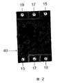
MEA内部のGDLの多孔質性の特性のせいで、バイポーラプレートのシーリング溝に導入されたシール材は、GDLに浸透してMEAのマニホルドポートをシールする。シーリング後のMEA40の燃料流動場面の写真を図2に示してあり、ここではMEA40は、カセットから切り出して、酸化剤19および冷却剤17ポートがシールされて、燃料ポート15が開放されたままであることを示している。従来式方法においては、ポリマー膜は、GDLを超えて延びて、シール目的のフレームを提供することが必要であった。結果的に、これは、製造コストを増大させることになる。それとは異なり、本発明は、GDLおよびポリマー膜が、実質的に同一の寸法および形状のときに、シーリングを行うことを可能にする。このことは、本発明において使用するMEAが、製造コストを相応に低減した上で、連続的に製作することができるので、有利である。
Depending on the length and shape of the groove, the sealant flow from the edge of the assembly may not be adequate to completely seal the port. In such a case, a sealant hole is cut into the component and used to draw additional sealant directly into the sealing groove.
Due to the porous nature of the GDL inside the MEA, the sealing material introduced into the sealing groove of the bipolar plate penetrates the GDL and seals the manifold port of the MEA. A photograph of the fuel flow scene of the
図3は、シーリング溝が切り込まれた、バイポーラプレートの好ましい実施態様を示す。バイポーラプレート20の両側に、シーリング溝23が追加されている。そのようなシーリング溝23は、流動場チャネルパターン11が妨害されることなく、カセットを通して適切な反応物流を提供しなくてはならないので、バイポーラプレート20面上の流動場チャネルパターン11に接続されていない。これらのシーリング溝23の設計は、バイポーラプレート20の燃料流動場面において、燃料ポート15が開放されたままとなり燃料を配送するのに対して、残りの酸化剤ポート19および冷却剤ポート17はシールされるように、設計されている。バイポーラプレート20の反対側の酸化剤流動場面において、酸化剤ポート19は開放されたままとなり、酸化剤を分配するのに対して、その他のすべてのポートはシールされている。図4に、バイポーラプレート20の酸化剤流動場面を示してある。すなわち、シーリング溝23は、燃料吸入ポートおよび燃料排出ポート15ならびに冷却剤吸入ポートおよび冷却剤排出しポート17を包囲するが、酸化剤吸入ポートおよび酸化剤排出ポート19は包囲していない。
FIG. 3 shows a preferred embodiment of the bipolar plate with the sealing groove cut. Sealing
次に図4を参照すると、バイポーラプレート20用の、シーリング溝23およびシール材穴21の代替設計を示してあり、ここではシール材穴21が使用されており、シール材は、シール材穴21から引き込まれて(または押し込まれて)、燃料ポート15および冷却剤ポート17を包囲するシーリング溝23に入り、シール材は組立体の周囲から引き込まれて、構成要素の周囲だけをシールする。シール材穴は、MEAにも追加しなくてはならない。
Referring now to FIG. 4, an alternative design for the sealing
シーリング溝およびシール材穴パターンの別の実施態様を、図5のバイポーラプレート20上に示してある。図のように、シール材は、シール材穴21から引き込まれて、燃料ポート15および冷却剤ポート17をシールする。外周9およびポートを包囲するシーリング溝23は、組立体の外周9まわりのシーリング溝と隔離されている。この実施態様においては、外周の接合には、組立体全体を外部カプセル化する必要がなく、これは熱除去に対して有利である場合がある。
図6は、シーリングチャネルおよびシール材穴のパターンの、さらに別の実施態様を示し、ここではシーリング溝23には、周囲9およびシール材穴21の両方を介してシール材が供給され、燃料ポート15および冷却剤ポート17をシールする。
Another embodiment of a sealing groove and sealant hole pattern is shown on the
FIG. 6 shows yet another embodiment of a pattern of sealing channels and sealant holes, where the sealing
適当なシール材穴および/またはシーリングチャネルが、上述のように、燃料電池構成要素のそれぞれに切り込まれるかまたはその他の方法で形成されると、望ましいカセット設計および出力要件によって、構成要素を組み立てる。バイポーラプレートを利用する燃料電池スタックの組立には、ターミナルプレートを使用してもよく、このターミナルプレートには、バイポーラプレート構造の半分だけ、すなわち1つの流動場面だけが実装される。
非常に基礎的な組立設計においては、図7に示すように、MEA13は、2つのターミナルプレート25aおよび25bの間に配置される。しかしながら、別の好ましい実施態様における、組立設計では、ターミナルプレート、MEA、バイポーラプレート、第2のMEA、および第2のターミナルプレートをこの順番で含む。
Once suitable sealant holes and / or sealing channels are cut or otherwise formed in each of the fuel cell components, as described above, the components are assembled according to the desired cassette design and output requirements. . A terminal plate may be used to assemble a fuel cell stack that utilizes a bipolar plate, which is mounted on only half of the bipolar plate structure, ie, only one flow scene.
In a very basic assembly design, the
追加のバイポーラプレートおよびMEAを、完成燃料電池に対する出力要件に応じて、冷却層を追加するか、または追加せずに、カセット組立体に追加することができる。通常、複数のMEAを有する燃料電池は、冷却剤層の間に配置された1から約10のMAEを有する、反復ユニットを含む。さらに一般的には、約2から約4のMAEが冷却剤層の間に配置されており、これが、MEA濃度の最大化と、カセットまたはスタック全体の十分な熱除去の維持との間のバランスをとる。 Additional bipolar plates and MEAs can be added to the cassette assembly with or without additional cooling layers, depending on the power requirements for the finished fuel cell. Typically, a fuel cell having a plurality of MEAs includes a repeating unit having 1 to about 10 MAEs disposed between the coolant layers. More generally, about 2 to about 4 MAEs are placed between the coolant layers, which balances between maximizing MEA concentration and maintaining sufficient heat removal of the entire cassette or stack. Take.
次に図17を参照すると、隣接する冷却剤流動場84の間に配置された2つのMEA13を有する、特に好ましい反復ユニットを示してある。この反復ユニットは、2つのMEA層13、1つの燃料流動場72および酸化剤流動場74を有するバイポーラプレート70、冷却剤流動場84および酸化剤流動場74(または燃料流動場72)のいずれかを有する2つのバイポーラプレート80(および82)を含む。したがって、バイポーラプレート80と82とは、プレートのいずれかの端で、中央マニホルドポートを通過する鏡面によって関係づけられる。この冷却剤流動場84は実質的に対称である。バイポーラプレート80および82の反対側面上の流動場は非対称であり、冷却剤流動場が「上」面、すなわちプレート82であるか、または「下」面、すなわちプレート80であるかによって、燃料流動場または酸化剤流動場のいずれかを形成することになる。冷却剤流動場のその他の配設および構造は、容易に決定することができ、それらは本発明の範囲にあることを、当業者は認識するであろうが、図17に示す構造は、構成要素が少なく、2種類のバイポーラプレート(例えば、プレート80および70)だけであるので、低コストでのより大量の生産に適している。
Referring now to FIG. 17, a particularly preferred repeat unit having two
燃料電池用途の使用に対して、本発明のカセットは、通常、次の構成要素:膜電極接合体(MEA)、流動場、およびセパレータプレートを含む、スタック式組立体の形態で使用される。
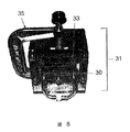
例示組立体設計について記述したが、燃料電池は、最終燃料電池カセットの出力要件に応じて、一緒に組み立てた任意所望の数の構成要素を有することができることを、当業者は認識するであろう。特定の設計とは関係なく、組立体内の各構成要素のポートが、その他の構成要素のポートと位置合わせされるように、構成要素が組み立てられる。図8に示すように、組立体30は、型またはキャビティー31内に配置されて、簡単なクランプまたはボルトパターンなどの適当な圧縮手段35を用いて、上端プレート33によって型内部の定位置に保持される。シール材穴を利用する場合には、上端プレートも、シール材をそこから組立体に導入することのできる穴を包含することになる。
For use in fuel cell applications, the cassettes of the present invention are typically used in the form of a stacked assembly that includes the following components: membrane electrode assembly (MEA), flow field, and separator plate.
While an exemplary assembly design has been described, those skilled in the art will recognize that a fuel cell can have any desired number of components assembled together, depending on the output requirements of the final fuel cell cassette. . Regardless of the particular design, the components are assembled such that the ports of each component in the assembly are aligned with the ports of the other components. As shown in FIG. 8, the
真空式樹脂トンラスファー成形技法を使用して上述の燃料電池カセット組立体をシールするために、すべての組立構成要素の、外周まわりおよびシール材穴中に、シール材を導入する。組立体内部のポートのそれぞれを介して真空に引く。圧力差によって、シール材が組立体の縁端中に引き込まれ、それによって組立体内の構成要素の周囲が互いにシールされ、組立体が最終燃料電池カセットに形成される。さらに、同じ圧力差によって、バイポーラプレートに切り込まれた溝の中に、シール材が引き込まれる。シール材穴が存在する場合には、圧力差によって、シール材を、シール材穴を介して溝の中へ吸引するか、または別の方法で引き込む。またシール材は、溝および縁端から、隣接するMAEのGDLに浸透する。外周およびポートのシーリングは、シール材が、溝を通って流れて、適当なポートに達して、それをシールするとともに、MEAの隣接する部分を塞ぐと完了する。 In order to seal the above-described fuel cell cassette assembly using a vacuum resin ton-laser molding technique, a sealant is introduced around the outer periphery and in the sealant holes of all assembly components. A vacuum is pulled through each of the ports inside the assembly. The pressure differential causes the sealant to be drawn into the edge of the assembly, thereby sealing the components around the assembly together and forming the assembly in the final fuel cell cassette. Furthermore, the sealing material is drawn into the groove cut in the bipolar plate by the same pressure difference. If a sealant hole is present, the pressure differential causes the sealant to be sucked into the groove or otherwise drawn through the sealant hole. Further, the sealing material penetrates into the adjacent MAE GDL from the groove and the edge. The perimeter and port sealing is complete when the sealant flows through the groove to reach the appropriate port to seal it and plug adjacent portions of the MEA.
カセット組立体の全体にわたって、各流動場が適切にシールされて、その結果として、対象とするマニホルドポートだけが、個々の層上で開放されたままとなる。残りのポートは、すでにシールされた溝によって、選択的に阻止/包囲される。組立体の縁端は、また、シール材によってカプセル化される。シーリング工程を達成するのに必要な圧力差および時間は、構成要素およびシール材用に使用される材料の関数であり、それには、それに限定はされないが、シーリング溝の形状、シール材の粘性および流動特性、およびMEAに使用するガス拡散層の種類などがある。 Throughout the cassette assembly, each flow field is properly sealed so that only the manifold ports of interest remain open on the individual layers. The remaining ports are selectively blocked / surrounded by the already sealed grooves. The edge of the assembly is also encapsulated by a seal. The pressure differential and time required to accomplish the sealing process is a function of the components and materials used for the sealant, including but not limited to the shape of the sealing groove, the viscosity of the sealant and There are the flow characteristics and the type of gas diffusion layer used for MEA.
代替手法として、圧力式樹脂トランスファーを使用して、低粘性シール材を、シール材穴の中および/または組立体の周囲まわりに押し込むことができる。粘度が150,000cP未満、より好ましくは100,000cP未満の二液性熱硬化性樹脂(two part thermoset resins )によって、シーリングチャネルおよびスタック外部の充填を、最小の駆動圧力(<10PSI)において非常に短い充填時間(<1分)で行うことが可能となる。さらに、燃料電池構成要素およびシーリングチャネルの設計が、高圧力充填技術および通常要求されるよりも厳しい公差による派生効果によって、複雑化することがない。 As an alternative, a pressure resin transfer can be used to push the low viscosity seal into the seal hole and / or around the periphery of the assembly. Two-part thermoset resins with viscosities of less than 150,000 cP, more preferably less than 100,000 cP, greatly reduce the filling of the sealing channels and the stack outside at a minimum driving pressure (<10 PSI). It is possible to carry out in a short filling time (<1 minute). Furthermore, the design of fuel cell components and sealing channels is not complicated by high pressure filling techniques and the derivation effects due to tighter tolerances than are normally required.
射出成形技法を使用して燃料電池カセットをシールするためには、組立体の周囲まわり、およびすべてのシール材穴の中に、シール材を機械的に押し込む。好ましい一実施態様においては、シール材として使用する熱硬化樹脂を、注入穴の中、および組立体の縁端まわりに注入して、燃料電池カセットを型から取り外す前に硬化させる。別の実施態様においては、熱可塑性樹脂をシール材として使用する。このシール材は、注入穴の中、および組立体の縁端まわりに注入して、燃料電池カセットを型から取り外す前に、冷却して硬化させる。関連する温度および圧力に対処することのできる型を使用する。 To seal the fuel cell cassette using injection molding techniques, the sealant is mechanically pushed around the periphery of the assembly and into all the sealant holes. In a preferred embodiment, a thermosetting resin used as a sealant is injected into the injection hole and around the edge of the assembly to cure the fuel cell cassette before removing it from the mold. In another embodiment, a thermoplastic resin is used as the sealing material. This sealant is injected into the injection hole and around the edge of the assembly and allowed to cool and harden before the fuel cell cassette is removed from the mold. Use molds that can handle the associated temperature and pressure.
したがって、本明細書において提供する、燃料電池および関連する電気化学的カセットを製造する方法は、迅速なプロトタイプ設計および最適化を可能にする。これらの製造方法は、さらに、樹脂トランスファー成形または低圧射出成形技法のいずれかを使用する、電気化学的または燃料電池カセットの少量から中量(すなわち、<100,000ユニット)の生産に好適である。特に、本発明のカセットは、減少/低圧力で製造することができる。さらに、本発明のカセットは、所与のカセット寸法に対して、電気化学的に活性な大きな断面積を有する。すなわち、シーリングの目的で使用しなくてはならない(犠牲にする)カセットの部分が少ない。 Accordingly, the method of manufacturing a fuel cell and associated electrochemical cassette provided herein allows for rapid prototype design and optimization. These manufacturing methods are further suitable for the production of small to medium quantities (ie, <100,000 units) of electrochemical or fuel cell cassettes using either resin transfer molding or low pressure injection molding techniques. . In particular, the cassette of the present invention can be manufactured with reduced / low pressure. Furthermore, the cassette of the present invention has a large electrochemically active cross-sectional area for a given cassette size. That is, there are few cassette parts that must be used (sacrificed) for sealing purposes.
本発明の低圧シーリング技法に必要となる、小さい断面積によって、カセット内での試薬の供給および流動場からの排除においてより高い柔軟性が得られる。結果として、流動場における試薬消耗が減少するか、または解消される。すなわち、例えば、各流動場に、2つまたは3つ以上の試薬マニホルドからの試薬を供給し、廃液を2つまたは3つ以上の排出マニホルドを介して流動場から除去することもできる。
流動場設計の柔軟性が向上することで、カセット効率が向上し、またさらにカセット設計の拡張性がもたらされる。すなわち、本発明の意図するカセットは、同様の電力出力を有する既存の燃料電池よりも概して小さいカセットにより生成される、比較的大きなまたは比較的小さな電力出力を有するものである。
The small cross-sectional area required for the low pressure sealing technique of the present invention provides greater flexibility in reagent supply and exclusion from the flow field within the cassette. As a result, reagent consumption in the flow field is reduced or eliminated. That is, for example, each flow field can be supplied with reagents from two or more reagent manifolds, and the waste fluid can be removed from the flow fields via two or more discharge manifolds.
The increased flexibility of the flow field design improves cassette efficiency and further expands the cassette design. That is, the intended cassette of the present invention is one having a relatively large or relatively small power output produced by a generally smaller cassette than existing fuel cells having similar power output.
周囲およびポートをシールするのに使用するシール材の選択は、作動燃料電池システムにおいて見られる条件に対して、そのシール材が、必要な化学的および機械的な特性、例えば、それに限定はされないが、温度安定性などを有するようにする。適当なシール材としては、熱可塑性プラスチックおよび熱硬化性エラストマーの両方がある。好ましい熱可塑性プラスチックには、熱可塑性オレフィンエラストマー類、熱可塑性ポリウレタン、プラストマー、ポリプロピレン、ポリエチレン、ポリテトラフルオロエチレン、フッ化ポリプロピレンおよびポリスチレンがある。好ましい熱硬化性エラストマーとしては、エポキシ樹脂類、ウレタン類、シリコーン類、フルオロシリコーン類、およびビニルエステル類がある。 The choice of sealant used to seal the surroundings and ports is such that the sealant has the necessary chemical and mechanical properties, such as, but not limited to, the conditions found in working fuel cell systems. To have temperature stability and the like. Suitable sealing materials include both thermoplastics and thermoset elastomers. Preferred thermoplastics include thermoplastic olefin elastomers, thermoplastic polyurethanes, plastomers, polypropylene, polyethylene, polytetrafluoroethylene, fluorinated polypropylene and polystyrene. Preferred thermosetting elastomers include epoxy resins, urethanes, silicones, fluorosilicones, and vinyl esters.
図9に示す代替実施態様においては、上述のシーリング段階の間に、エンドプレート3aおよび3bが直接、燃料電池カセット1に接着37される。この実施態様を使用することで、いくつかの便益が生じる。エンドプレート間で燃料電池カセットを圧縮する必要をなくすることによって、燃料電池スタックの信頼性が向上し、かつ実質的に重量が減少する。また、組み込まれるエンドプレートに取付部品を含めて、それによって燃料電池スタックをさらに簡略化することができる。好ましい一実施態様においては、外部の燃料、酸化剤および冷却剤の流れへの接続を、スタックに使用するターミナルプレートに追加して、その結果、ターミナルプレートがスタックのエンドプレートとして機能する。
In the alternative embodiment shown in FIG. 9, the
次に図13を参照すると、本発明の燃料電池カセットの使用に適した、ある好ましい複合膜電極接合体は、積層膜電極接合体13を含み、これは、その周囲のまわりを、熱硬化性または熱可塑性ラストマー材料からなるガスケット52で包囲されている。一般的に、好ましいのは、熱硬化性材料、特にシリコーン材料からなるガスケットを有する、膜電極接合体である。複合MEAは、市販されている。例えば、3Mの3M Fuel Cell Components Programによって製造された、顧客対応MEAを参照されたい。
その他の好ましい複合膜電極接合体は、触媒層(ある場合には)の部分を有する積層膜電極接合体と、周囲から除去したガス拡散層とを含み、その結果として、イオン導電性層が、複合膜電極接合体の周囲まわりに露出される。
Referring now to FIG. 13, one preferred composite membrane electrode assembly suitable for use with the fuel cell cassette of the present invention includes a laminated
Other preferred composite membrane electrode assemblies include a laminated membrane electrode assembly having a portion of a catalyst layer (if present) and a gas diffusion layer removed from the surroundings so that the ion conductive layer is It is exposed around the periphery of the composite membrane electrode assembly.
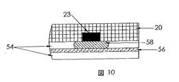
次に図10を参照すると、ある好ましい実施態様においては、ある真空式樹脂トランスファー成形技法および圧力式樹脂トランスファー成形技法を使用して、(スタック外部の外部縁端から、またはシール材穴を介して導入する)シール材をシーリングチャネル23の中に引き込むことができる。チャネル23がシール材で満たされると、さらなる真空によって、シール材が、チャネル23と接触する、GDL54の一部に引き込まれる。好ましくは、シール材は、チャネル23と接触するGDL54のその部分で、シールが液密または気密になるように、非多孔質複合材58を形成する。本発明のこの実施態様は、製造を容易にすることにおいて好ましい。特に、この実施態様では、カセットの組立およびカプセル化の以前に、MEAの修正がほとんど必要ではない。すなわち、それは、燃料電池カセットの大量生産用に好ましいシーリング手段である。
Referring now to FIG. 10, in one preferred embodiment, certain vacuum and pressure resin transfer molding techniques are used (from the outer edge outside the stack or through the sealant holes). The sealing material can be drawn into the sealing
この特定の実施態様では、シール材とGDLとの間に、かなり複雑な相互作用を必要とすること、またより広範な最適化を必要とする場合があることに留意されたい。理想的には、シール材は、GDLの孔隙を完全に塞ぐべきである(これは、すべての動作モードにおいては必要でない)。この相互作用は、GDL(特に何らかの表面処理)およびシール材の化学的特性が、整合性があることを必要とする(すなわち、通常、GDL内の孔隙を塞ぐには、シール材がGDLをよく濡らすことが必要である)点において、開発において面倒になることがある。したがって、以下に開示するその他のシーリング手段が、少量から中量の規模の生産、例えば約104ユニット程度の生産に好ましい場合がある。 Note that this particular implementation may require a rather complex interaction between the seal and the GDL, and may require more extensive optimization. Ideally, the sealant should completely close the GDL pores (this is not necessary in all modes of operation). This interaction requires that the GDL (especially any surface treatment) and the chemical properties of the sealant be consistent (ie, the sealant generally does not perform well with the GDL to plug pores in the GDL). Can be cumbersome in development. Therefore, other sealing means disclosed below, scale production medium volume from a small amount, may be preferred, for example, about 104 units about the production.
次に図11および12を参照すると、上記の直接実行に対するいくつかの代替案があり、それは、電気化学的電池の製造ならびにその開発の両方において有利である場合がある。MEA製造業者は、現在、組込み縁端ガスケット52および/またはGDL層54を越えて延びる膜56縁端を備える複合MEA50を製造している。これらの複合MEA50は、チャネルシーリング概念においても直接使用することができる。MEA13のGDL部分に隣接するシール材チャネル23を備えるのではなく、それを複合MEA50(図11を参照)のガスケット52上に配置することができる。シール材チャネル23に引き込まれるか、または押し込まれたシール材は、次いで、複合MEA50のガスケット52の材料と直接的にシールを形成することができる。いくつかの実施態様においては、これは、シール材とGDLとの直接相互作用の心配なしに、MEAの特性(GDLの種類、表面処理)を変更することができるので、有利なことがある。
Referring now to FIGS. 11 and 12, there are several alternatives to the direct implementation described above, which may be advantageous both in the manufacture of electrochemical cells as well as in their development. MEA manufacturers currently manufacture
図12に示すように、MEA13の周囲を包囲するガスケット52に対するシール材チャネル23の別の配置は、シール材が、GDL54に対するとともに、包囲するガスケット52の一部に対して接着することを可能にする。すなわち、シーリングチャネル23は、複合MEA50に隣接し、その結果、チャネル23は、ガスケット52と、GDL54のいくらかの部分との両方に露出される(図12を参照)。これが有利である理由は、シール材と縁端ガスケットとの相互作用が、GDLと相互作用することなく、確実なシールを形成することができ、それでもシール材はGDL中に引き込まれ、処理中に複合材58を形成する(シーリング工程の信頼性を向上させる)からである。
As shown in FIG. 12, another arrangement of the
さらに、複合MEAのガスケット部分をシーリングすると、MEA表面と接触する流動場に導入されていない試薬への、そのMEA表面の露出を、最少化または防止する。さらに具体的には、燃料および酸化剤を供給するマニホルド開口が、通常は電気化学的に活性ではない複合MEAのガスケット部分にのみ露出される。したがって、酸化剤流動場と接触しているMEAの表面は、複合MEAの積層GDL/MEA構造が、例えば、燃料マニホルドと接触していないので、その表面の燃料への露出が防止される。 Further, sealing the gasket portion of the composite MEA minimizes or prevents exposure of the MEA surface to reagents not introduced into the flow field that contact the MEA surface. More specifically, the manifold openings for supplying fuel and oxidant are only exposed to the gasket portion of the composite MEA that is not normally electrochemically active. Thus, the surface of the MEA that is in contact with the oxidant flow field is prevented from exposing the surface of the composite MEA to the fuel, for example, because the laminated GDL / MEA structure of the composite MEA is not in contact with the fuel manifold.
冷却剤マニホルドを含むカセットにおいては、マニホルド開口は、好ましくは、複合MEAのガスケット部分だけに露出させる。そのような配設によって、MEAおよび/またはカセットへの冷却剤誘起損傷が、低減または防止される。
本発明の新規な構成によって、MEAの同一表面の部分を酸化剤および燃料に露出させることによって、いくつかの燃料電池カセットにおいて観察されることのある「短絡」過程が回避される。この短絡過程は、大部分はMEAの同一表面の一部が酸化剤および燃料に露出されることに起因し、この結果として、MEA層からの電力出力が低下すること、例えば、MEA表面と接触していない流動場に導入されていない試薬へ露出されたMEAの部分が、MEAの有効表面積を減少させることになる。その結果として、MEAの表面積に比例する、燃料電池電気出力も減少する。
In cassettes containing coolant manifolds, the manifold openings are preferably exposed only on the gasket portion of the composite MEA. Such an arrangement reduces or prevents coolant-induced damage to the MEA and / or cassette.
The novel configuration of the present invention avoids the “short circuit” process that may be observed in some fuel cell cassettes by exposing portions of the same surface of the MEA to oxidant and fuel. This short-circuit process is largely due to a portion of the same surface of the MEA being exposed to oxidant and fuel, resulting in a decrease in power output from the MEA layer, eg, contact with the MEA surface. The portion of the MEA that is exposed to the reagent that has not been introduced into the non-flowing field will reduce the effective surface area of the MEA. As a result, the fuel cell electrical output, which is proportional to the surface area of the MEA, also decreases.
非複合MEAを含む本発明の別の燃料電池、すなわちMEAおよびGDL積層が燃料電池スタックの周囲まで延びるMEAにおいては、MEAの厚みを貫通するマニホルド開口は、バイポーラプレートのシーリングチャネルの機能と干渉することなく、最大断面積を有するように切り開かれる。より具体的には、燃料または酸化剤マニホルドに対応する、MEAを貫通するマニホルド開口は、バイポーラプレートのシーリングチャネル内のシール材によって塞がれているGDLの部分の内側に画定される領域とほぼ同一の形状である断面にまで拡大されている。 In another fuel cell of the present invention that includes non-composite MEAs, ie, MEAs in which the MEA and GDL stacks extend to the periphery of the fuel cell stack, the manifold opening through the thickness of the MEA interferes with the function of the sealing channel of the bipolar plate. Without being cut to have a maximum cross-sectional area. More specifically, the manifold opening through the MEA, corresponding to the fuel or oxidant manifold, is approximately the region defined inside the portion of the GDL that is plugged by the seal in the sealing channel of the bipolar plate. It is expanded to a cross section having the same shape.
図14を参照すると、燃料、酸化剤および任意選択で冷却剤マニホルドと位置合わせされた、MEA内の開口15、17、および19は、最大化された断面を有する。そうすることによって、酸化剤マニホルドまたは燃料マニホルド内に存在する酸化剤または燃料に露出される、MEAの部分はわずかであるか、またはまったくない。理論に拘束されるのを望むわけではないが、異なるマニホルド内の試薬および廃液流へのMEAの露出を最少化することによって、試薬および冷却剤を燃料電池の異なる流動場に提供すると、流動場と接触するMEAの寸法を増大させることなく、高い電力生成が得られると思われる。
Referring to FIG. 14, the
別の観点では、本発明は、燃料電池、電気化学的またはイオン交換用途に適するスタックを提供する。本発明のスタックは、少なくとも1つの本発明のカセット、およびカセットの試薬マニホルド開口と位置合わせされた開口を有する、少なくとも1つのエンドプレートを備える。各カセットは、試薬マニホルド開口が位置合わせされるように、互いに組み立てられる。エンドプレートは、エンドプレート内の開口が試薬マニホルド開口と位置合わせされるように、燃料電池カセットのスタックの上端および/または下端に組み付ける。 In another aspect, the present invention provides a stack suitable for fuel cell, electrochemical or ion exchange applications. The stack of the present invention comprises at least one end plate having at least one cassette of the present invention and an opening aligned with the reagent manifold opening of the cassette. Each cassette is assembled together so that the reagent manifold openings are aligned. The end plate is assembled to the upper and / or lower end of the stack of fuel cell cassettes so that the opening in the end plate is aligned with the reagent manifold opening.
本発明が提供する燃料電池スタックを形成するために、エンドプレートおよび燃料電池カセットを組み立てる手段は、特に限定されるものではなく、圧縮ガスケットシールならびに樹脂および/またはシール材内への共同カプセル化を含めることができる。好ましい実施態様においては、エンドプレートは、樹脂によるカプセル化以前で、かつシール材の導入以前に燃料電池カセットに組み付けて、その結果、エンドプレートと燃料電池カセットとを組み合わせて、例えば同時に、カプセル化してシールする。
本発明の他の好ましい実施態様においては、1つまたは2つ以上の燃料電池カセットを製造し、次いで、1つまたは2つ以上の圧縮ガスケットおよびエンドプレートと一緒に、互いにスタックに配置する。貫通ボルト、束縛(tie down)またはその他の機械式締結具などの圧縮手段を、燃料電池スタックに取り付けて、燃料電池カセットおよびエンドプレートを機械的にシールする。
The means for assembling the end plate and the fuel cell cassette to form the fuel cell stack provided by the present invention is not particularly limited, and includes a compression gasket seal and joint encapsulation within the resin and / or sealant. Can be included. In a preferred embodiment, the end plate is assembled to the fuel cell cassette before encapsulating with the resin and before the introduction of the sealing material, so that the end plate and the fuel cell cassette are combined, for example encapsulated simultaneously. And seal.
In another preferred embodiment of the invention, one or more fuel cell cassettes are manufactured and then placed in a stack together with one or more compression gaskets and end plates. Compression means such as through bolts, tie downs or other mechanical fasteners are attached to the fuel cell stack to mechanically seal the fuel cell cassette and end plate.
本発明のカセットまたはスタックにおける層寸法および層数は、特に限定はされない。一般に、各流動場および/または膜接合体は、約1cm2から約1m2の間であるが、ある種の用途においては、比較的大きいおよび比較的小さい流動場層および/または膜接合体層が適当であることがある。本発明の燃料電池カセットにおける層寸法と層数は、様々な用途に対して十分な電力供給を生成するように構成することができる。しばしば、本発明の燃料電池カセットの電力出力は、約0.1Wから約100kWの範囲、またはより好ましくは約0.5Wから約1または10kWの範囲になる。本発明の、その他の好ましい燃料電池カセットは、約5Wから約1kWまでの範囲となる。 The layer size and the number of layers in the cassette or stack of the present invention are not particularly limited. In general, each flow field and / or membrane assembly is between about 1 cm 2 and about 1 m 2 , but in certain applications, relatively large and relatively small flow field layers and / or membrane assembly layers. May be appropriate. The layer dimensions and number of layers in the fuel cell cassette of the present invention can be configured to produce a sufficient power supply for various applications. Often, the power output of the fuel cell cassette of the present invention will be in the range of about 0.1 W to about 100 kW, or more preferably in the range of about 0.5 W to about 1 or 10 kW. Other preferred fuel cell cassettes of the present invention range from about 5 W to about 1 kW.
カプセル化に使用される樹脂またはシール材の選択は、作動燃料電池システムにおいて見られる条件に対して要求される化学的および機械的特性(例えば、酸化剤安定性)を有するように行う。適当な樹脂/シール材には、熱可塑性プラスチックおよび熱硬化性エラストマーの両方がある。好ましい熱可塑性プラスチックとしては、熱可塑性オレフィンエラストマー類、熱可塑性ポリウレタン、プラストマー、ポリプロピレン、ポリエチレン、ポリテトラフルオロエチレン、フッ素化ポリプロピレンおよびポリスチレンがある。好ましい熱硬化性エラストマーには、エポキシ樹脂類、ウレタン類、シリコーン類、フッ化シリコーン類、およびビニルエステル類がある。 The choice of resin or sealant used for encapsulation is made to have the chemical and mechanical properties (eg, oxidant stability) required for conditions found in working fuel cell systems. Suitable resin / seal materials include both thermoplastics and thermoset elastomers. Preferred thermoplastics include thermoplastic olefin elastomers, thermoplastic polyurethanes, plastomers, polypropylene, polyethylene, polytetrafluoroethylene, fluorinated polypropylene and polystyrene. Preferred thermosetting elastomers include epoxy resins, urethanes, silicones, fluorinated silicones, and vinyl esters.
シーリング工程を達成するのに必要な圧力差および時間は、燃料電池カセット構築に使用する材料の関数である。これらには、シール材チャネル形状、樹脂の粘性および流動特性、およびMEAに使用するガス拡散層の種類がある。当業者であれば、これらのパラメータに基づいて適切な時間および圧力を判断することができるであろう。また、本発明を実施する者は、組立体の最上層に樹脂の変化をそこから見ることのできる透明型を使用して、シーリング工程中に目視検査することによって、最も適当な時間および圧力を確認することもできる。
本発明の好ましい燃料電池カセットを、以下の説明用の実施態様によって、さらに説明するが、この説明用の実施態様は、説明のためだけのものであり、本発明をそこに開示する特定の成分および量に限定するものではない。
The pressure differential and time required to achieve the sealing process is a function of the materials used to construct the fuel cell cassette. These include the sealant channel shape, resin viscosity and flow characteristics, and the type of gas diffusion layer used for MEA. One skilled in the art will be able to determine the appropriate time and pressure based on these parameters. Also, the practitioner of the present invention uses the transparent mold from which the resin changes can be seen from the top layer of the assembly, and visually inspects it during the sealing process to provide the most appropriate time and pressure. It can also be confirmed.
Preferred fuel cell cassettes of the present invention are further illustrated by the following illustrative embodiments, which are illustrative only and specific components disclosed therein. And is not limited to quantities.
実施例1
真空式樹脂トランスファー成形
図3に示す溝およびシール材穴のパターンを使用して、バイポーラプレートを、ポリマーグラファイト複合材中に(片側に酸化剤流動場、反対側に燃料流動場を備えて)機械加工した。MEAは、既知の工程を使用して製作し、図7に示すパターンに従って、例えば、マニホルド穴と同一パターンを有するバイポーラプレートと同一の外部寸法に、名目どおり切り出した。6つのMEA、5つのバイポーラプレート、および2つのターミナルプレートを、図8に示す型内で、次の順序で組み立てた。すなわち、ターミナルプレート、MEA、バイポーラプレート、MEA、バイポーラプレート、MEA、バイポーラプレート、MEA、バイポーラプレート、MEA、バイポーラプレート、MEA、ターミナルプレートの順である。組立体は、シリコーン樹脂Silastic M(米国、ミシガン州ミドランド、Dow Corning Corporation市販)を用いて、23インチHgの真空で約90秒間かけてカプセル化した。
Example 1
Vacuum Resin Transfer Molding Using the groove and sealant hole pattern shown in Figure 3, the bipolar plate is machined into a polymer graphite composite (with oxidant flow field on one side and fuel flow field on the other side). processed. The MEA was fabricated using known processes and cut nominally into the same external dimensions as, for example, a bipolar plate having the same pattern as the manifold holes, according to the pattern shown in FIG. Six MEAs, five bipolar plates, and two terminal plates were assembled in the following sequence within the mold shown in FIG. That is, the order is terminal plate, MEA, bipolar plate, MEA, bipolar plate, MEA, bipolar plate, MEA, bipolar plate, MEA, bipolar plate, MEA, terminal plate. The assembly was encapsulated using a silicone resin Silastic M (commercially available from Dow Corning Corporation, Midland, Michigan, USA) at 23 inches of Hg vacuum for about 90 seconds.
実施例2
圧力式樹脂トランスファー成形
燃料電池スタックは、エンドプレート、複合MEAおよびバイポーラプレートから、シリコーン中へのカプセル化によって製作した。エンドプレートは、水素入出力、空気入出力、および冷却剤入出力、ならびにシール材追加用穴、のためのマニホルドに対応するねじ切り穴を有するアルミニウムから機械加工した。これらのエンドプレートは、接触抵抗および腐食安定性を改良するために金でコーティングし、それによって、エンドプレートと電流収集装置としての機能を果した。MEAは、より大きな5層片(触媒およびガス拡散層を両側に有する膜)から切り出し、シリコーンガスケットを、周囲に接着した(例えば、図13を参照)。MEAのガスケット部分に、マニホルドポートおよびシール材穴に対応して、穴をパンチ加工した。バイポーラプレートは、2つの変種:燃料流動場および酸化剤流動場[A−A]を備えるもの、ならびに燃料流動場および冷却剤流動場[A−B]を備えるものを、グラファイトポリマー複合材から機械加工した。スタックは、次の順番の部品で製作した。
Example 2
Pressure Resin Transfer Molding A fuel cell stack was fabricated from an end plate, composite MEA and bipolar plate by encapsulation in silicone. The end plates were machined from aluminum with threaded holes corresponding to manifolds for hydrogen input / output, air input / output, and coolant input / output and sealant addition holes. These end plates were coated with gold to improve contact resistance and corrosion stability, thereby functioning as end plates and current collectors. The MEA was cut from a larger five-layer piece (a membrane with catalyst and gas diffusion layers on both sides) and a silicone gasket was glued around (see, eg, FIG. 13). Holes were punched in the MEA gasket portion corresponding to the manifold port and the seal material hole. Bipolar plates are machined from graphite polymer composites with two variants: those with a fuel flow field and an oxidant flow field [AA], and those with a fuel flow field and coolant flow field [AB]. processed. The stack was made with the following parts:
エンドプレート、バイポーラプレート[B−A]、MEA、バイポーラプレート[A−A]、MEA、バイポーラプレート[A−B]、バイポーラプレート[B−A]、MEA、バイポーラプレート[A−A]、MEA、バイポーラプレート「A−B」、エンドプレート。
この組立体を、図8に示す型と同様な型に配置して、位置決めして軽く締め付けた。2液性シリコーンSilastic T2(米国、ミシガン州The Dow Corning Corporation of Midlandが市販)を、静的ミキサを介して手操作で汲み上げ(<5PSI)て、4つのシール材ポートのそれぞれに入れた。未硬化のシリコーンは、シール材マニホルドを通過して、シール材チャネルを介してスタック全体に移動する。スタックの外部は、シール材マニホルドを介して樹脂を継続的に押出すことによって、未硬化の樹脂で包囲し、それによって閉じ込められた空気を放出した。スタックおよび型は、80℃の炉で1時間で迅速に硬化させた、一旦、結果として得られる燃料電池スタックを型から外すと、全体の適当なシーリングを保証するために、10PSIまでの漏れ試験を実施した。
End plate, bipolar plate [BA], MEA, bipolar plate [AA], MEA, bipolar plate [AB], bipolar plate [BA], MEA, bipolar plate [AA], MEA Bipolar plate “A-B”, end plate.
This assembly was placed in a mold similar to the mold shown in FIG. 8, positioned and lightly clamped. A two-part silicone Silastic T2 (commercially available from The Dow Corning Corporation of Midland, Michigan, USA) was manually pumped through a static mixer (<5 PSI) and placed in each of the four sealant ports. Uncured silicone passes through the seal manifold and travels through the seal channel through the stack. The exterior of the stack was surrounded by uncured resin by continuously extruding the resin through the seal manifold, thereby releasing trapped air. The stack and mold were cured rapidly in an oven at 80 ° C. for 1 hour. Once the resulting fuel cell stack was removed from the mold, a leak test up to 10 PSI was ensured to ensure proper overall sealing. Carried out.
ある動作モードにおいては、(特に、反応物を、数PSIよりな大きな圧力にする場合に)この燃料電池スタックにいくらかの締め付けを加えるのが好ましいことがある。これは、任意の外部機械的手段によって達成することができる。さらに、スタックの内部を貫通するねじを、シール材およびカプセル化ステップ後(しかし、シール材が硬化する前)に、シール材穴に挿入することによって追加した。その結果は、燃料電池内部にカプセル化された内部圧縮手段である。ねじおよびナットを使用するか、代わりに下部エンドプレート内のシール材穴にねじ切りして、挿入したねじが、上部エンドプレートを貫通して、下部エンドプレートにねじ込まれるようにすることができる。電気的に絶縁された層(すなわち絶縁スリーブ)をねじに加えて、スタック構成要素内部の短絡を防止するのが有利なこともある。 In certain modes of operation, it may be preferable to apply some clamping to this fuel cell stack (especially when the reactants are at a pressure greater than a few PSI). This can be achieved by any external mechanical means. In addition, screws through the interior of the stack were added by inserting into the sealant holes after the sealant and encapsulation step (but before the sealant hardened). The result is an internal compression means encapsulated inside the fuel cell. Screws and nuts can be used, or alternatively threaded into a seal hole in the lower end plate, so that the inserted screw penetrates the upper end plate and is screwed into the lower end plate. It may be advantageous to add an electrically isolated layer (ie an insulating sleeve) to the screw to prevent a short circuit inside the stack component.
実施例3
標準射出成形
自動射出成形を利用する上で、上述の方式を、ほとんど変更をすることがない。2液性樹脂(例えば、実施例1で使用したシリコーン)を使用することによって、真空に引くのではなく、内部ポートに圧力をかけることによって、樹脂をチャネルに注入できることを示した。熱可塑性樹脂の従来型射出成形に対して、使用する型は、関連する温度および圧力に対処しなくてはならない。溶融樹脂を、注入穴の中および組立体の縁端まわりに注入して、冷却、硬化させる。注入速度特性、パック圧力、および冷却時間は、構成要素損傷の可能性を最小化すること、ならびに収縮/歪曲を制御して最終部分のシーリングを確保するために、最適化される。最後に、燃料電池カセットを型から取り外す。
本発明の以上の記述は、単に説明のためのものであり、本発明の主旨または範囲から逸脱することなく、変更および修正を行うことができると理解される。
Example 3
Standard Injection Molding When using automatic injection molding, the above method is hardly changed. It was shown that by using a two-part resin (eg, the silicone used in Example 1), the resin could be injected into the channel by applying pressure to the internal port rather than pulling a vacuum. In contrast to conventional injection molding of thermoplastics, the mold used must handle the associated temperature and pressure. Molten resin is injected into the injection holes and around the edges of the assembly to cool and cure. Injection rate characteristics, pack pressure, and cooling time are optimized to minimize the possibility of component damage and to control shrinkage / distortion to ensure final part sealing. Finally, the fuel cell cassette is removed from the mold.
It will be understood that the foregoing description of the invention is merely illustrative and that changes and modifications can be made without departing from the spirit or scope of the invention.
Claims (39)
(b)反応物マニホルド開口(単数または複数)と位置合わせされた、1つまたは2つ以上の開口を有する、少なくとも1つのエンドプレートを含む燃料電池スタックであって、
前記エンドプレートが、1つまたは2つ以上の電気化学的カセットの、スタックの上端および/または下端に組み付けられ、その結果、前記エンドプレートの開口が、燃料マニホルド開口、酸化剤開口、および任意選択で冷却剤マニホルド開口と位置合わせされている、前記燃料電池スタック。(A) at least one electrochemical cassette according to any of claims 1 to 4;
(B) a fuel cell stack comprising at least one end plate having one or more openings aligned with the reactant manifold opening (s),
The end plate is assembled to the top and / or bottom of the stack of one or more electrochemical cassettes so that the opening of the end plate is a fuel manifold opening, an oxidant opening, and optionally Wherein the fuel cell stack is aligned with the coolant manifold opening.
Applications Claiming Priority (2)
| Application Number | Priority Date | Filing Date | Title |
|---|---|---|---|
| US37463102P | 2002-04-23 | 2002-04-23 | |
| PCT/US2003/012684 WO2003092096A2 (en) | 2002-04-23 | 2003-04-23 | Membrane based electrochemical cell stacks |
Publications (3)
| Publication Number | Publication Date |
|---|---|
| JP2006502530A JP2006502530A (en) | 2006-01-19 |
| JP2006502530A5 JP2006502530A5 (en) | 2006-06-15 |
| JP4585310B2 true JP4585310B2 (en) | 2010-11-24 |
Family
ID=29270529
Family Applications (1)
| Application Number | Title | Priority Date | Filing Date |
|---|---|---|---|
| JP2004500351A Expired - Lifetime JP4585310B2 (en) | 2002-04-23 | 2003-04-23 | Membrane electrochemical cell stack |
Country Status (6)
| Country | Link |
|---|---|
| EP (1) | EP1502313B1 (en) |
| JP (1) | JP4585310B2 (en) |
| AT (1) | ATE545963T1 (en) |
| AU (1) | AU2003231755B2 (en) |
| CA (1) | CA2483394C (en) |
| WO (1) | WO2003092096A2 (en) |
Families Citing this family (15)
| Publication number | Priority date | Publication date | Assignee | Title |
|---|---|---|---|---|
| US7687181B2 (en) | 2002-04-23 | 2010-03-30 | Protonex Technology Corporation | Channel-based electrochemical cassettes |
| WO2004047210A2 (en) * | 2002-11-18 | 2004-06-03 | Protonex Technology Corporation | Membrane based electrochemical cell stacks |
| JP2006519468A (en) | 2003-02-27 | 2006-08-24 | プロトネクス テクノロジー コーポレーション | Electrochemical cell stack based on externally manifolded membrane |
| DE10358052A1 (en) * | 2003-12-05 | 2005-06-30 | Stefan Dr. Nettesheim | Fuel cell arrangement for electrochemical fuel cells comprises a membrane-electrode structure arranged between two profiled electrically conducting separator plates |
| KR100528339B1 (en) * | 2003-10-01 | 2005-11-15 | 삼성에스디아이 주식회사 | Direct liquid feed fuel cell stack |
| FR2863780B1 (en) * | 2003-12-15 | 2009-01-23 | Helion | PLATE FOR SUPPLYING A FUEL CELL WITH COPLANAR CIRCULATING. |
| JP4855707B2 (en) * | 2005-04-20 | 2012-01-18 | 住友軽金属工業株式会社 | Aluminum plate for fuel cell, separator using the same, end plate and fuel cell using them. |
| US7879507B2 (en) | 2006-04-10 | 2011-02-01 | Protonex Technology Corporation | Insert-molded, externally manifolded, one-shot sealed membrane based electrochemical cell stacks |
| KR100830980B1 (en) * | 2007-05-28 | 2008-05-20 | 삼성에스디아이 주식회사 | Stack for fuel cell |
| US8580457B2 (en) | 2007-06-28 | 2013-11-12 | Protonex Technology Corporation | Fuel cell stack sealed with encapsulating material and method of making the same |
| US8124292B2 (en) | 2007-06-28 | 2012-02-28 | Protonex Technology Corporation | Fuel cell stacks and methods |
| WO2009006220A1 (en) * | 2007-06-28 | 2009-01-08 | Protonex Technology Corporation | Fuel cell stacks and methods |
| KR101724972B1 (en) * | 2015-12-15 | 2017-04-10 | 현대자동차주식회사 | Fuel battery cell |
| US11502349B2 (en) | 2020-08-31 | 2022-11-15 | Borgwarner, Inc. | Cooling manifold assembly |
| DE202022100954U1 (en) | 2022-02-18 | 2022-03-31 | Rheinisch-Westfälische Technische Hochschule (Rwth) Aachen | Flow cell with improved structure |
Family Cites Families (13)
| Publication number | Priority date | Publication date | Assignee | Title |
|---|---|---|---|---|
| US4371433A (en) * | 1980-10-14 | 1983-02-01 | General Electric Company | Apparatus for reduction of shunt current in bipolar electrochemical cell assemblies |
| JPS62256380A (en) * | 1986-04-29 | 1987-11-09 | Shin Kobe Electric Mach Co Ltd | Liquid fuel cell |
| US4786568A (en) * | 1988-03-01 | 1988-11-22 | International Fuel Cells Corporation | Electrode substrate with integral edge seal and method of forming the same |
| JP3244779B2 (en) * | 1992-07-06 | 2002-01-07 | 三菱重工業株式会社 | Fuel cell |
| US5527363A (en) * | 1993-12-10 | 1996-06-18 | Ballard Power Systems Inc. | Method of fabricating an embossed fluid flow field plate |
| CA2296384C (en) * | 1997-07-16 | 2004-09-28 | Ballard Power Systems Inc. | Resilient seal for membrane electrode assembly (mea) in an electrochemical fuel cell and method of making same |
| JP3481093B2 (en) * | 1997-09-22 | 2003-12-22 | 三洋電機株式会社 | Cell unit for fuel cell |
| JPH11233128A (en) * | 1998-02-17 | 1999-08-27 | Honda Motor Co Ltd | Fuel cell |
| JP4321887B2 (en) * | 1998-08-20 | 2009-08-26 | パナソニック株式会社 | Solid polymer fuel cell and manufacturing method thereof |
| US6413664B1 (en) * | 1999-12-23 | 2002-07-02 | Ballard Power Systems Inc. | Fuel cell separator plate with discrete fluid distribution features |
| JP4401554B2 (en) * | 2000-09-04 | 2010-01-20 | 本田技研工業株式会社 | Fuel cell |
| JP3532547B2 (en) * | 2000-11-30 | 2004-05-31 | 本田技研工業株式会社 | Method for manufacturing seal-integrated separator |
| US6852439B2 (en) * | 2001-05-15 | 2005-02-08 | Hydrogenics Corporation | Apparatus for and method of forming seals in fuel cells and fuel cell stacks |
-
2003
- 2003-04-23 JP JP2004500351A patent/JP4585310B2/en not_active Expired - Lifetime
- 2003-04-23 EP EP03747307A patent/EP1502313B1/en not_active Expired - Lifetime
- 2003-04-23 AU AU2003231755A patent/AU2003231755B2/en not_active Ceased
- 2003-04-23 WO PCT/US2003/012684 patent/WO2003092096A2/en active Application Filing
- 2003-04-23 AT AT03747307T patent/ATE545963T1/en active
- 2003-04-23 CA CA2483394A patent/CA2483394C/en not_active Expired - Lifetime
Also Published As
| Publication number | Publication date |
|---|---|
| WO2003092096A2 (en) | 2003-11-06 |
| CA2483394A1 (en) | 2003-11-06 |
| WO2003092096A3 (en) | 2004-04-01 |
| CA2483394C (en) | 2011-09-20 |
| AU2003231755B2 (en) | 2009-04-23 |
| JP2006502530A (en) | 2006-01-19 |
| ATE545963T1 (en) | 2012-03-15 |
| AU2003231755A1 (en) | 2003-11-10 |
| EP1502313B1 (en) | 2012-02-15 |
| EP1502313A4 (en) | 2008-05-28 |
| EP1502313A2 (en) | 2005-02-02 |
Similar Documents
| Publication | Publication Date | Title |
|---|---|---|
| JP5270164B2 (en) | Membrane electrochemical cell stack | |
| US8232015B2 (en) | One-shot fabrication of membrane based electrochemical cell stacks | |
| CA2516765C (en) | Externally manifolded membrane based electrochemical cell stacks | |
| JP4346905B2 (en) | Electrochemical polymer electrolyte membrane battery stack | |
| CA2506592C (en) | Membrane electrode assembly with periphery gasket and sealing channels | |
| JP4585310B2 (en) | Membrane electrochemical cell stack | |
| AU2008270558B2 (en) | Fuel cell stacks and methods | |
| AU2003295710A1 (en) | Membrane based electrochemical cell stacks |
Legal Events
| Date | Code | Title | Description |
|---|---|---|---|
| A072 | Dismissal of procedure [no reply to invitation to correct request for examination] |
Free format text: JAPANESE INTERMEDIATE CODE: A072 Effective date: 20051018 |
|
| A521 | Request for written amendment filed |
Free format text: JAPANESE INTERMEDIATE CODE: A523 Effective date: 20060421 |
|
| A621 | Written request for application examination |
Free format text: JAPANESE INTERMEDIATE CODE: A621 Effective date: 20060421 |
|
| A131 | Notification of reasons for refusal |
Free format text: JAPANESE INTERMEDIATE CODE: A131 Effective date: 20100330 |
|
| A521 | Request for written amendment filed |
Free format text: JAPANESE INTERMEDIATE CODE: A523 Effective date: 20100630 |
|
| TRDD | Decision of grant or rejection written | ||
| A01 | Written decision to grant a patent or to grant a registration (utility model) |
Free format text: JAPANESE INTERMEDIATE CODE: A01 Effective date: 20100817 |
|
| A01 | Written decision to grant a patent or to grant a registration (utility model) |
Free format text: JAPANESE INTERMEDIATE CODE: A01 |
|
| A61 | First payment of annual fees (during grant procedure) |
Free format text: JAPANESE INTERMEDIATE CODE: A61 Effective date: 20100903 |
|
| R150 | Certificate of patent or registration of utility model |
Ref document number: 4585310 Country of ref document: JP Free format text: JAPANESE INTERMEDIATE CODE: R150 Free format text: JAPANESE INTERMEDIATE CODE: R150 |
|
| FPAY | Renewal fee payment (event date is renewal date of database) |
Free format text: PAYMENT UNTIL: 20130910 Year of fee payment: 3 |
|
| R250 | Receipt of annual fees |
Free format text: JAPANESE INTERMEDIATE CODE: R250 |
|
| R250 | Receipt of annual fees |
Free format text: JAPANESE INTERMEDIATE CODE: R250 |
|
| R250 | Receipt of annual fees |
Free format text: JAPANESE INTERMEDIATE CODE: R250 |
|
| R250 | Receipt of annual fees |
Free format text: JAPANESE INTERMEDIATE CODE: R250 |
|
| R250 | Receipt of annual fees |
Free format text: JAPANESE INTERMEDIATE CODE: R250 |
|
| R250 | Receipt of annual fees |
Free format text: JAPANESE INTERMEDIATE CODE: R250 |
|
| R250 | Receipt of annual fees |
Free format text: JAPANESE INTERMEDIATE CODE: R250 |
|
| R250 | Receipt of annual fees |
Free format text: JAPANESE INTERMEDIATE CODE: R250 |
|
| R250 | Receipt of annual fees |
Free format text: JAPANESE INTERMEDIATE CODE: R250 |
|
| R250 | Receipt of annual fees |
Free format text: JAPANESE INTERMEDIATE CODE: R250 |
|
| EXPY | Cancellation because of completion of term |