JP4583014B2 - Battery case and battery - Google Patents
Battery case and battery Download PDFInfo
- Publication number
- JP4583014B2 JP4583014B2 JP2003334402A JP2003334402A JP4583014B2 JP 4583014 B2 JP4583014 B2 JP 4583014B2 JP 2003334402 A JP2003334402 A JP 2003334402A JP 2003334402 A JP2003334402 A JP 2003334402A JP 4583014 B2 JP4583014 B2 JP 4583014B2
- Authority
- JP
- Japan
- Prior art keywords
- battery
- layer
- conductor
- electrode plate
- recess
- Prior art date
- Legal status (The legal status is an assumption and is not a legal conclusion. Google has not performed a legal analysis and makes no representation as to the accuracy of the status listed.)
- Expired - Fee Related
Links
Images


Classifications
-
- Y—GENERAL TAGGING OF NEW TECHNOLOGICAL DEVELOPMENTS; GENERAL TAGGING OF CROSS-SECTIONAL TECHNOLOGIES SPANNING OVER SEVERAL SECTIONS OF THE IPC; TECHNICAL SUBJECTS COVERED BY FORMER USPC CROSS-REFERENCE ART COLLECTIONS [XRACs] AND DIGESTS
- Y02—TECHNOLOGIES OR APPLICATIONS FOR MITIGATION OR ADAPTATION AGAINST CLIMATE CHANGE
- Y02E—REDUCTION OF GREENHOUSE GAS [GHG] EMISSIONS, RELATED TO ENERGY GENERATION, TRANSMISSION OR DISTRIBUTION
- Y02E60/00—Enabling technologies; Technologies with a potential or indirect contribution to GHG emissions mitigation
- Y02E60/10—Energy storage using batteries
-
- Y—GENERAL TAGGING OF NEW TECHNOLOGICAL DEVELOPMENTS; GENERAL TAGGING OF CROSS-SECTIONAL TECHNOLOGIES SPANNING OVER SEVERAL SECTIONS OF THE IPC; TECHNICAL SUBJECTS COVERED BY FORMER USPC CROSS-REFERENCE ART COLLECTIONS [XRACs] AND DIGESTS
- Y02—TECHNOLOGIES OR APPLICATIONS FOR MITIGATION OR ADAPTATION AGAINST CLIMATE CHANGE
- Y02P—CLIMATE CHANGE MITIGATION TECHNOLOGIES IN THE PRODUCTION OR PROCESSING OF GOODS
- Y02P70/00—Climate change mitigation technologies in the production process for final industrial or consumer products
- Y02P70/50—Manufacturing or production processes characterised by the final manufactured product
Description
本発明は、充電式電池に使用される電池用ケースおよび電池に関し、より詳しくは携帯電話などの小型電子機器に用いられる薄型の電池用ケースおよび電池に関する。 The present invention relates to a battery case and battery used for a rechargeable battery, and more particularly to a thin battery case and battery used for small electronic devices such as mobile phones.
近年、携帯電話や携帯型コンピュータ、カメラ一体型ビデオテープレコーダー等に代表される携帯機器が目覚しく発達するとともに、より一層の小型化、軽量化が求められる傾向にある。そして、これらの携帯機器の電源としての電池の需要も増加の一途をたどるとともに、電池のエネルギー密度を高めることによる小型軽量化の研究が活発に行われている。特に、リチウム電池は、原子量が小さくかつイオン化エネルギーが大きなリチウムを用いる電池であることから、高エネルギー密度を得ることができて小型軽量化が図れ、さらに再充電が可能な電池とできることより盛んに研究され、現在に至っては携帯機器の電源をはじめとする広範囲な用途に用いられるようになってきた。 In recent years, portable devices typified by mobile phones, portable computers, camera-integrated video tape recorders, etc. have been remarkably developed, and further miniaturization and weight reduction have been demanded. In addition, the demand for batteries as power sources for these portable devices continues to increase, and research on reducing the size and weight by increasing the energy density of the batteries is actively conducted. In particular, the lithium battery is a battery using lithium with a small atomic weight and a large ionization energy, so that it is possible to obtain a high energy density, to achieve a reduction in size and weight, and to be a battery that can be recharged more actively. It has been researched and has now been used for a wide range of applications including power supplies for portable devices.
また、電池には、大きく分けて円筒型と角型があり、その構造は正極と負極とを絶縁シートから成るセパレータを介して金属製の電槽缶内に収容し、そこに電解液が注入されて封口された構造とされている。 Batteries can be broadly divided into cylindrical and square types. The structure is that the positive and negative electrodes are housed in a metal battery case through a separator made of an insulating sheet, and an electrolyte is injected there. It is a sealed structure.
リチウム電池の正極には、例えば金属酸化物を正極活物質としてこれに導電材を添加したものが一般的に使用される。この正極活物質としては例えばコバルト酸リチウム(LiCoO2)やマンガン酸リチウム(LiMn2O4)などが使用され、また、導電材としては例えばアセチレンブラック(AB)や黒鉛などが使用される。電池の負極には、チタン酸リチウム(Li4Ti5O12)などのリチウムチタン複合酸化物やグラファイトまたは非晶質炭素などの活物質を樹脂で固めたものが使用される。 As a positive electrode of a lithium battery, for example, a metal oxide used as a positive electrode active material and a conductive material added thereto is generally used. For example, lithium cobaltate (LiCoO 2 ) or lithium manganate (LiMn 2 O 4 ) is used as the positive electrode active material, and acetylene black (AB) or graphite is used as the conductive material. As the negative electrode of the battery, a lithium titanium composite oxide such as lithium titanate (Li 4 Ti 5 O 12 ) or an active material such as graphite or amorphous carbon solidified with a resin is used.
リチウム電池においては、このLiCoO2やLiMn2O4などから成る正極活物質の充放電電圧が約4Vであり、これに対して炭素材料などから成る負極活物質の充放電電圧は0V付近であることから、これらの正極活物質と負極活物質と電解液とを組み合わせることによって約3.5Vの高放電電圧を達成している。 In the lithium battery, the charge / discharge voltage of the positive electrode active material made of LiCoO 2 or LiMn 2 O 4 is about 4V, while the charge / discharge voltage of the negative electrode active material made of carbon material or the like is around 0V. Therefore, a high discharge voltage of about 3.5 V is achieved by combining these positive electrode active material, negative electrode active material, and electrolyte.
電池の正極は上記活物質に上記導電材を加え、さらにポリテトラフルオロエチレンやポリフッ化ビニリデンなどのバインダを添加、混合してスラリー状となし、これを周知のドクターブレード法を用いてシート状に成形し、ついでこのシートを例えば円形状に裁断して作製される。 For the positive electrode of the battery, the conductive material is added to the active material, and a binder such as polytetrafluoroethylene or polyvinylidene fluoride is added and mixed to form a slurry, which is formed into a sheet using a well-known doctor blade method. The sheet is formed and then cut into, for example, a circular shape.
また負極は上記活物質に、正極と同様にポリテトラフルオロエチレンやポリフッ化ビニリデンなどのバインダを添加、混合してスラリー状となし、これを周知のドクターブレード法を用いてシート状に成形し、ついでこのシートを例えば円形状に裁断して作製される。 Also, the negative electrode is added to the above active material, as in the positive electrode, a binder such as polytetrafluoroethylene or polyvinylidene fluoride, mixed to form a slurry, and this is formed into a sheet using a known doctor blade method, Next, this sheet is cut into a circular shape, for example.
そして、このようにして作製された正極および負極をその間に耐熱温度が約150℃のポリオレフィン繊維製の不織布やポリオレフィン製の微多孔膜などからなるセパレータを介して電槽缶内に収容し、電解液を注入して電池が得られる。 Then, the positive electrode and the negative electrode thus prepared are accommodated in a battery case via a separator made of a polyolefin fiber nonwoven fabric or a polyolefin microporous film having a heat resistant temperature of about 150 ° C. A battery is obtained by pouring the liquid.
そして、このようにして作製される電池をさらに小型化、高密度化するために、図6に示すコイン型の電池Aが開発されている。 In order to further reduce the size and density of the battery thus manufactured, a coin-type battery A shown in FIG. 6 has been developed.
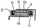
この従来の電池Aは、円板状の正極11bを備えた例えばステンレスからなる正極缶11と、円板状の負極12bを備えた例えばステンレスからなる負極缶12とを電解液を含浸させたセパレータ14を介して対置させ、ついで例えば絶縁性のポリプロピレン樹脂からなるガスケット15を介して正極缶11の周囲と負極缶12の周囲とをかしめるようにして一体に結合させた電槽缶構造とされている。正極11bおよび負極12bにおける充放電は正極缶11および負極缶12に取着した外部接続端子部材を介して行われる(例えば、下記の特許文献1,2参照)。
しかしながら、特許文献1,2に示されるような従来の電池Aは、長期間に亘って温度幅が百数十度という温度サイクル試験(例えば−40℃〜85℃)に曝されると、例えばポリプロピレン樹脂からなるガスケット15と正極缶11と負極缶12との熱膨張率の差によりガスケット15を介して正極缶11および負極缶12の周囲をかしめた電槽缶の結合部位に隙間が生じて電解液が漏れ出す場合が有り、これにより電池Aの電池性能を劣化させたり、さらに漏れ出た電解液により外部電気回路基板上の銅(Cu)配線が腐食して断線するといった不具合が発生したり、あるいは、この隙間から水分が電池A内部に侵入して電池性能を劣化させるという不具合が発生していた。
However, when the conventional battery A as shown in
さらには、従来の電池Aは正極缶11と負極缶12はステンレスからなるため、熱伝導率が高く、電池A内部が電池A外部の温度の影響を受けやすく、電池性能が劣化し易いという問題点もあった。即ち、電池A外部の温度が上昇した場合、電解液が電池A外部の温度変化に追従して大きく温度変化し易く、所望の電池性能を発揮させることができなかった。 Furthermore, since the conventional battery A has a positive electrode can 11 and a negative electrode can 12 made of stainless steel, the thermal conductivity is high, the battery A is easily affected by the temperature outside the battery A, and the battery performance is likely to deteriorate. There was also a point. That is, when the temperature outside the battery A rises, the electrolyte easily changes greatly following the temperature change outside the battery A, and the desired battery performance cannot be exhibited.
従って、本発明は上記問題点に鑑みて完成されたものであり、その目的は、長期間の使用により電槽缶の結合部位に隙間が生じることにより電解液が漏れ出して電池性能を劣化させたり、漏出した電解液により外部電気回路基板が損傷を受けたりすることがなく、外部電気回路基板への接続が容易で、電池性能が周囲の温度変化に影響され難い量産性に優れた電池用ケースおよび電池を提供することにある。 Accordingly, the present invention has been completed in view of the above-mentioned problems, and its purpose is to deteriorate the battery performance due to leakage of the electrolyte due to the formation of a gap in the joint portion of the battery case due to long-term use. For the battery with excellent mass productivity, the external electric circuit board is not damaged by the leaked electrolyte, the connection to the external electric circuit board is easy, and the battery performance is not affected by the ambient temperature change. It is to provide a case and a battery.
本発明の電池用ケースは、上面の中央部に直方体状の凹部が形成され、前記凹部内の内側面に形成された段差であって、前記凹部の底面よりも高い位置に該段差の上面が位置する段差を有し、下面に第一の導体層および第二の導体層が互いに独立して設けられたセラミックスから成る基体と、前記凹部の底面に形成された第一のメタライズ層と、前記段差の上面に形成された第二のメタライズ層と、前記第一のメタライズ層から前記第一の導体層にかけて前記基体を貫通して形成された第一の内部導体と、前記第二のメタライズ層から前記第二の導体層にかけて前記基体を貫通して形成された第二の内部導体と、を具備しており、前記基体の熱伝導率が20W/m・K以下であることを特徴とするものである。
The battery case of the present invention has a rectangular parallelepiped recess formed at the center of the upper surface, and is a step formed on the inner surface of the recess, the upper surface of the step being higher than the bottom surface of the recess. has a step located, a substrate made of ceramics which is provided a first conductor layer and second conductor layer independently of each other on the lower surface, the first metallized layer formed on the bottom surface of the recess, the A second metallization layer formed on the upper surface of the step, a first inner conductor formed through the base from the first metallization layer to the first conductor layer, and the second metallization layer and anda second internal conductor formed through said substrate toward said second conductor layer from, and wherein the thermal conductivity of the substrate is not more than 20W / m · K Is.
また、本発明の電池用ケースは、上記構成において好ましくは、前記第一の内部導体の断面積は前記第二の内部導体の断面積よりも小さいことを特徴とするものである。 In the battery case of the present invention, preferably, the cross-sectional area of the first inner conductor is smaller than the cross-sectional area of the second inner conductor.
本発明の電池は、上記構成の電池用ケースと、前記第一のメタライズ層に接続された正電極板と、該正電極板の上面に電解液を含浸した絶縁シートを介して密着するように載置されるとともに前記第二のメタライズ層に接続された負電極板と、前記凹部を覆うようにして接合された蓋体と、を具備していることを特徴とするものである。
The battery of the present invention is in close contact with the battery case having the above configuration, the positive electrode plate connected to the first metallization layer, and the upper surface of the positive electrode plate via an insulating sheet impregnated with an electrolyte. a negative electrode plate connected to the second metallization layer while being placed, is characterized in that it comprises a and a lid joined so as to cover the recess.
本発明の電池用ケースは、上面の中央部に直方体状の凹部が形成され、下面に第一の導体層および第二の導体層が互いに独立して設けられたセラミックスから成る基体と、前記凹部の底面に形成された第一のメタライズ層と、前記基体の上面に形成された第二のメタライズ層と、前記第一のメタライズ層から前記第一の導体層にかけて前記基体を貫通して形成された第一の内部導体と、前記第二のメタライズ層から前記第二の導体層にかけて前記基体を貫通して形成された第二の内部導体と、を具備しており、前記基体の熱伝導率が20W/m・K以下であることを特徴とするものである。
The battery case of the present invention has a rectangular parallelepiped recess formed in the center of the upper surface, and a base made of ceramics having a first conductor layer and a second conductor layer provided independently on the lower surface, and the recess a first metallized layer formed on the bottom surface of the second metallized layer formed on the upper surface of the substrate, is formed through the base toward said first conductive layer from said first metallized layer A first inner conductor and a second inner conductor formed through the substrate from the second metallization layer to the second conductor layer , and a thermal conductivity of the substrate. Is 20 W / m · K or less.
また、本発明の電池用ケースは、上記構成において好ましくは、前記第一の内部導体の断面積は前記第二の内部導体の断面積よりも小さいことを特徴とするものである。 In the battery case of the present invention, preferably, the cross-sectional area of the first inner conductor is smaller than the cross-sectional area of the second inner conductor.
また、本発明の電池は、上記構成の電池用ケースと、前記第一のメタライズ層に接続された正電極板と、該正電極板の上面に電解液を含浸した絶縁シートを介して密着するように載置された負電極板と、前記凹部を覆うようにして接合されるとともに少なくとも下側主面が導電性とされ、前記負電極板および前記第二のメタライズ層に接続された蓋体と、を具備していることを特徴とするものである。 The battery of the present invention is in close contact with the battery case having the above-described configuration, the positive electrode plate connected to the first metallization layer, and the upper surface of the positive electrode plate via an insulating sheet impregnated with an electrolyte. The negative electrode plate placed so as to cover the recess, and at least the lower main surface is made conductive, and the lid is connected to the negative electrode plate and the second metallization layer. When, and is characterized in that it comprises a.
本発明の電池用ケースは、上面の中央部に直方体状の凹部が形成され、下面に第一の導体層および第二の導体層が互いに独立して設けられたセラミックスから成る基体と、凹部の底面に形成された第一のメタライズ層と、凹部の内側面と底面との間に形成された段差のに形成された第二のメタライズ層と、第一のメタライズ層から第一の導体層にかけて形成された第一の内部導体と、第二のメタライズ層から第二の導体層にかけて形成された第二の内部導体とを具備しており、基体の熱伝導率が20W/m・K以下であることより、電解液が気密性に優れるとともに耐熱性に優れるセラミックスから成る基体によって収容されることとなり、電解液を良好に収容することができ、温度サイクル試験に曝された場合でも隙間が生じて電解液が漏れることがない。また、気密性が維持されるので、電池性能を劣化させる水分や酸素等が外部から電解液中に侵入するのを有効に抑制することができる。 The battery case of the present invention has a rectangular parallelepiped recess formed at the center of the upper surface, a base made of ceramics on which the first conductor layer and the second conductor layer are provided independently of each other on the lower surface, From the first metallized layer formed on the bottom surface, the second metallized layer formed on the step formed between the inner surface and the bottom surface of the recess, and from the first metallized layer to the first conductor layer A first inner conductor formed and a second inner conductor formed from the second metallization layer to the second conductor layer, and the substrate has a thermal conductivity of 20 W / m · K or less. As a result, the electrolytic solution is accommodated by a base made of ceramics that is excellent in air tightness and heat resistance, so that the electrolytic solution can be accommodated satisfactorily and a gap is generated even when exposed to a temperature cycle test. Electrolyte leaks That there is no. In addition, since airtightness is maintained, it is possible to effectively prevent moisture, oxygen, and the like that deteriorate battery performance from entering the electrolyte from the outside.
また、基体は有機溶剤や酸等を含む電解液に侵され難く、電解液中に基体から溶け出した不純物が混入しないので電解液を劣化させることもない。このため電池性能を良好に維持することができる。 In addition, the substrate is not easily attacked by an electrolytic solution containing an organic solvent, an acid, and the like, and impurities dissolved from the substrate are not mixed in the electrolytic solution, so that the electrolytic solution is not deteriorated. For this reason, battery performance can be maintained satisfactorily.
さらに、従来のように樹脂を介してかしめる部位を必要としないことから電池の外形を極限まで小さくすることができ、近時の小型化に適するものとなる。 Furthermore, since a portion that is caulked through a resin as in the prior art is not required, the outer shape of the battery can be reduced to the limit, which is suitable for recent miniaturization.
またさらには、基体の熱伝導率が20W/m・K以下と熱伝導率が低いので、電池内部が電池外部の温度の影響を受け難くなる。その結果、電池外部の温度が上昇した場合においても、電解液が電池外部の温度変化に追従して大きく温度変化することがなく、電解液の温度変化を極力抑え、常に所望の電池性能を発揮させることができる。 Furthermore, since the thermal conductivity of the substrate is as low as 20 W / m · K or less, the inside of the battery is hardly affected by the temperature outside the battery. As a result, even when the temperature outside the battery rises, the electrolyte does not change greatly following the temperature change outside the battery, and the temperature change of the electrolyte is suppressed as much as possible, and the desired battery performance is always exhibited. Can be made.
また、下面に第一の導体層および第二の導体層が形成されていることにより、第一および第二の導体層を外部電気回路基板の表面の配線導体に半田を介して接合させることによって、平板状の外部電気回路基板の配線導体と電池とを容易に接続させることができるので、外部電気回路基板の量産性に非常にすぐれたものとなる。 Further, by forming the first conductor layer and the second conductor layer on the lower surface, the first and second conductor layers are joined to the wiring conductor on the surface of the external electric circuit board via solder. Since the wiring conductor of the flat external electric circuit board and the battery can be easily connected, the mass production of the external electric circuit board is very good.
さらに、本発明の電池用ケースによれば、第一の内部導体の断面積は第二の内部導体の断面積よりも小さいことにより、第二の内部導体より短い第一の内部導体を介して電池外部より電池内部の電解液に伝わる熱を抑えることができる。従って、電池内部の温度上昇を有効に抑制できる結果、電解液の温度変化を極力抑え、常に所望の電池性能を発揮させることができる。加えて、第一の内部導体の抵抗値と第二の内部導体の抵抗値とを近づけることもできる。 Furthermore, according to the battery case of the present invention, the cross-sectional area of the first inner conductor is smaller than the cross-sectional area of the second inner conductor, so that the first inner conductor is shorter than the second inner conductor. Heat transmitted from the outside of the battery to the electrolyte inside the battery can be suppressed. Therefore, as a result of effectively suppressing the temperature rise inside the battery, the temperature change of the electrolytic solution can be suppressed as much as possible, and desired battery performance can always be exhibited. In addition, the resistance value of the first inner conductor can be made closer to the resistance value of the second inner conductor.
本発明の電池は、上記構成の電池用ケースと、第一のメタライズ層に接続された正電極板と、正電極板の上面に電解液を含浸した絶縁シートを介して密着するように載置されるとともに第二のメタライズ層に接続された負電極板と、凹部を覆うようにして接合された蓋体とを具備していることにより、上記構成の電池用ケースを用いた気密信頼性が高く、量産性に優れるものとなる。また、所望の電池性能を発揮させることができ、信頼性が高く、長期間に亘って安定して充放電することができるものとなる。 The battery of the present invention is placed in close contact with the battery case having the above configuration, the positive electrode plate connected to the first metallization layer, and the upper surface of the positive electrode plate via an insulating sheet impregnated with an electrolyte. And having a negative electrode plate connected to the second metallization layer and a lid joined so as to cover the recess, airtight reliability using the battery case having the above-described configuration is achieved. High and excellent in mass productivity. In addition, desired battery performance can be exhibited, reliability is high, and charging and discharging can be performed stably over a long period of time.
また、本発明の電池用ケースによれば、基体の上面の凹部の周囲に第二のメタライズ層を形成したときには、凹部の内側の段差を省略できることから、凹部内を広く有効に活用することができるので、電池用ケースの外形を小型化することができる。 Further, according to the battery case of the present invention, when the second metallized layer is formed around the recess on the upper surface of the base, the step inside the recess can be omitted, so that the inside of the recess can be used widely and effectively. Therefore, the outer shape of the battery case can be reduced in size.
また、本発明の電池は、基体の上面の凹部の周囲に形成された第二のメタライズ層を具備する電池用ケースと、第一のメタライズ層に接続された正電極板と、この正電極板の上面に電解液を含浸した絶縁シートを介して密着するように載置された負電極板と、凹部を覆うようにして接合されるとともに少なくとも下側主面が導電性とされ、負電極板および第二のメタライズ層に接続された蓋体とを具備していることにより、導電性とされている蓋体の下側主面の広い面と負電極板とを当接させて蓋体と負電極板とを接続させることによって、負電極板と蓋体との間の抵抗を少なくすることができ、負電極板と蓋体との間で電気的損失を発生させることなく効率よく充放電させることができるので、電気的特性に優れたものとできる。 In addition, the battery of the present invention includes a battery case having a second metallized layer formed around a recess on the upper surface of the base, a positive electrode plate connected to the first metallized layer, and the positive electrode plate A negative electrode plate placed so as to be in close contact with the upper surface of the substrate through an insulating sheet impregnated with an electrolytic solution, and joined so as to cover the recess, and at least the lower main surface is made conductive, and the negative electrode plate And a lid connected to the second metallization layer, the lid is brought into contact with a wide surface of the lower main surface of the lid made conductive and the negative electrode plate. By connecting the negative electrode plate, the resistance between the negative electrode plate and the lid can be reduced, and charging and discharging can be performed efficiently without causing electrical loss between the negative electrode plate and the lid. Therefore, the electrical characteristics can be improved.
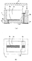
本発明の電池用ケースについて以下に詳細に説明する。図1において、(a)は本発明の電池用ケースの実施の形態の一例を示す断面図であり、(b)は(a)の電池用ケースの平面図を示す。 The battery case of the present invention will be described in detail below. 1A is a cross-sectional view showing an example of an embodiment of a battery case of the present invention, and FIG. 1B is a plan view of the battery case of FIG.
本発明の電池用ケースは、上面の中央部に直方体状の凹部1aが形成され、外面に第一の導体層1dおよび第二の導体層1eが互いに独立して設けられたセラミックスから成る基体1と、凹部1aの底面に形成された第一のメタライズ層1bと、凹部1aの内側面と底面との間に形成された段差1−Aの上面に形成された第二のメタライズ層1cと、第一のメタライズ層1bから第一の導体層1dにかけて形成された第一の内部導体2bと、第二のメタライズ層1cから第二の導体層1eにかけて形成された第二の内部導体2cとを具備しており、基体1の熱伝導率が20W/m・K以下とされる。
The battery case of the present invention is a
図1においては、基体1の凹部1aの底面に第一のメタライズ層1bが形成されるとともに凹部1aの内側面と底面との間に段差1−Aが形成され、段差1−Aの上面に第二のメタライズ層1cが形成されており、第一および第二の導体層1d,1eが基体1の下面に形成されている形態を示す。
In FIG. 1, a
第一および第二の導体層1d,1eが基体1の下面に形成されていることにより、第一および第二の導体層1d,1eを外部電気回路基板の表面の配線導体に半田を介して接合させることによって、平板状の外部電気回路基板の配線導体と電池とを容易に接続させることができるので、外部電気回路基板の量産性がよくなる。
Since the first and second conductor layers 1d and 1e are formed on the lower surface of the
このような基体1は、アルミナ質焼結体等の熱伝導率が20W/m・K以下であるセラミックスから成り、以下のようにして作製される。例えば、基体1がアルミナ質焼結体から成る場合、酸化アルミニウム(Al2O3),酸化珪素(SiO2),酸化マグネシウム(MgO),酸化カルシウム(CaO)等の原料粉末に適当な有機バインダ,溶剤等を添加混合してスラリーと成す。このスラリーをドクターブレード法やカレンダーロール法によってグリーンシートと成し、所要の大きさに切断する。次に、その中から選ばれた複数のグリーンシートにおいて凹部1a,段差1−A等を形成するために適当な打抜き加工を施す。
Such a
なお、基体1の熱伝導率を20W/m・K以下とするためには、基体1がアルミナ質焼結体から成る場合は、原料粉末である酸化アルミニウム(Al2O3)の配合割合を96質量%以下とすればよい。
In order to set the thermal conductivity of the
そして、これらのグリーンシートにタングステン(W)等の金属粉末を主成分とする金属ペーストを印刷塗布して第一のメタライズ層1b,第一の内部導体2b,第一の導体層1d,第二のメタライズ層1c,第二の内部導体2c,第二の導体層1e等の導体層となる印刷パターンを形成し、次いでこれらの印刷パターンを形成したグリーンシートを積層し、約1600℃の温度で焼成することによって導体層を備えた基体1が作製される。
Then, a metal paste mainly composed of a metal powder such as tungsten (W) is printed on these green sheets, and the
第一の導体層1dは、第一の内部導体2bを介して第一のメタライズ層1bと電気的に接続され、第二の導体層1eは第二の内部導体2cを介して第二のメタライズ層1cと電気的に接続される。そして、第一の導体層1dは電池の正極として用いられ、第二の導体層1eは負極として用いられる。この第一の導体層1dおよび第二の導体層1eが外部電気回路基板の表面の配線導体に半田を介して接合されることによって電池が外部の電気回路と電気的に接続される。
The
また、このようにして作製された基体1に形成されたこれら導体層の露出した表面には、耐食性に優れかつ半田との濡れ性に優れる金属、具体的には厚さ1〜12μmのニッケル(Ni)層および厚さ0.3〜5μmの金(Au)層をめっき法等により順次被着しておくのがよい。これにより、特に電池用ケースの内部に形成された第一のメタライズ層1bおよび第2のメタライズ層1cの金属成分が充放電による電圧で容易に溶出するのを有効に抑制できる。また、第一および第二の導体層1d,1eにおいては半田との濡れ性が良くなり、外部電気回路基板上の配線導体との半田を介した接合強度がより強固なものとなる。
Further, the exposed surfaces of these conductor layers formed on the
Ni層の厚さが1μm未満であれば、メタライズ層から成る各導体の酸化腐蝕を防止したり導体から金属成分が溶出したりするのを有効に抑制するのが困難になって電池性能が劣化し易くなる。また、Ni層の厚さが12μmを超えると、めっき形成に多大の時間がかかることになり量産性が低下し易くなるとともに電気抵抗が大きくなり易い。 If the thickness of the Ni layer is less than 1 μm, it becomes difficult to prevent the oxidative corrosion of each conductor made of the metallized layer and to effectively prevent the metal component from eluting from the conductor, and the battery performance deteriorates. It becomes easy to do. On the other hand, if the thickness of the Ni layer exceeds 12 μm, it takes a long time to form the plating, so that the mass productivity is likely to be lowered and the electric resistance is likely to be increased.
また、Au層の厚さが0.3μm未満であれば、均一な厚さのAu層を形成するのが困難となり、Au層がきわめて薄い部位やあるいはAu層が形成されていない部位が生じ易く、酸化腐食の防止効果や半田との濡れ性が低下し易くなる。Au層の厚さが5μmを超えると、めっき形成に多大の時間がかかることになり量産性が低下し易くなる。 Further, if the thickness of the Au layer is less than 0.3 μm, it is difficult to form an Au layer having a uniform thickness, and a portion where the Au layer is extremely thin or a portion where the Au layer is not formed is likely to occur. The effect of preventing oxidative corrosion and the wettability with solder are likely to decrease. If the thickness of the Au layer exceeds 5 μm, it takes a lot of time to form the plating, and the mass productivity tends to decrease.
セラミックスから成る基体1は、有機溶剤や酸等を含む電解液B−4に侵され難く、従って電解液B−4中に基体1から溶け出した不純物が混入して電解液B−4を劣化させることがない。このため電池性能を良好に維持することができる電池用ケースを得ることができる。
The
また、基体1の熱伝導率が20W/m・K以下であることにより、電池内部の温度が電池外部の温度の影響を受け難くなり、電池外部の温度が上昇した場合においても電解液B−4が電池外部の温度変化に追従して大きく温度変化することがない。電解液B−4の温度変化が極力電池外部の温度変化に追従することなく、電池Cの放電電圧を所望の電圧の80%未満に低下させない程度の温度変化の範囲に抑えられるので、常に所望の電池性能を発揮させることができる。基体1の熱伝導率が20W/m・Kを超えて大きくなると、電解液B−4の温度変化が電池外部の温度変化に追従して温度変化し、電池の電圧の変動が大きくなって、電池Cの放電電圧が所望の電圧の80%未満に低下してしまい、所望の電池性能を発揮させることができなくなる。
In addition, since the thermal conductivity of the
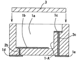
さらに、図2に断面図を示すように、第一の内部導体2bの断面積が第二の内部導体2cの断面積よりも小さいことにより、第二の内部導体2cより短い第一の内部導体2bを介して電池の下面より電池内部の電解液に伝わる熱を少なくすることができる。従って、電池内部の温度上昇を有効に抑制できる結果、電解液B−4の温度変化を極力抑え、常に所望の電池性能を発揮させることができる。ちなみに、本実施の形態の例においては、第一の内部導体2bが長さ0.25mm,直径0.1mm、第二の内部導体2cが長さ0.75mm,直径0.2mmとされている。
Further, as shown in the sectional view of FIG. 2, the first
また、第一の内部導体2bの断面積が第二の内部導体2cの断面積よりも小さいことよって、第一の内部導体2bの抵抗値と第二の内部導体2cの抵抗値とを近づけることもできる。
In addition, since the cross-sectional area of the first
なお、第一および第二の内部導体2b,2cは、図1では第一および第二の導体層1d,1eに対してそれぞれ垂直に連なる一本の層間接続導体(貫通導体)として示されているが、基体1の下面に形成された第一および第二の導体層1d,1eと平行な方向の内部配線層と垂直な層間接続導体とを複数組み合わせて形成されていてもよく、これによって基体1内に電気回路を引き回すことができるとともに、第一および第二の導体層1d,1eを基体1の所望の位置に形成することができる。
The first and second
また、基体1の上面には、アルミナ質焼結体,ムライト質焼結体等のセラミックスやアルミニウム(Al),銅(Cu),カーボン,鉄(Fe)−Ni−コバルト(Co)合金,Fe−Ni合金等の金属からなる蓋体3がAlロウ,銀(Ag)ロウ,Au−錫(Sn)半田等を用いたロウ付けや樹脂接着材等を用いた接着等の方法によって接合される。
On the upper surface of the
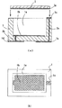
次に、本発明の電池用ケースの実施の形態の他の例として、図3に基体1の上面の凹部1aの周囲に第二のメタライズ層1cが形成されている形態を示す。同図において、(a)は電池用ケースの断面図、(b)は電池用ケースの平面図である。この形態によれば、凹部1aの内側の段差1−Aを省略できることから、凹部1a内を広く有効に活用することができるので、電池用ケースの外形を小型化することができる
基体1は図1の電池用ケースと同様のセラミックスから成り、蓋体3はAl,Cu,カーボン,Fe−Ni−Co合金,Fe−Ni合金等の導電性の材料から成る。または、アルミナ質焼結体,ムライト質焼結体等のセラミックスから成り、下側主面にW等のメタライズ層3aが形成されている。
Next, as another example of the embodiment of the battery case of the present invention, FIG. 3 shows a form in which a
好ましくは、蓋体3は基体1側の下側主面のほぼ全面にW等のメタライズ層3aが形成され、アルミナ質焼結体,ムライト質焼結体等の基体1と同一のセラミックスから成るのがよい。そして、メタライズ層3aが第二のメタライズ層1cと電気的に接続されて基体1の上面に凹部1aを覆うようにして接合される。この構成によって、蓋体3の上側主面が導電性とされず、蓋体3の上面に不要な電流が流れるのを防止することができる。従って、蓋体3の上側主面に導電性の部材が接触しても電気的短絡等の不具合が発生するのを有効に防止できる。また、蓋体3の熱膨張率が基体1の熱膨張率とほぼ同一となることから、電池用ケースに熱が加わっても基体1と蓋体3の接合部に熱膨張差による応力が大きく加わることを防止し、基体1にクラック等の破損が生ずるのを有効に防止することができ、気密信頼性に優れた電池用ケースとすることができる。
Preferably, the
次に、本発明の電池について以下に詳細に説明する。図4は図1の電池用ケースを用いた本発明の電池の実施の形態の一例(これを電池Cとする)を示す断面図、図5は図3の電池用ケースを用いた本発明の電池の実施の形態の他の例(これを電池Dとする)を示す断面図である。ここで、B−1は正電極板、B−2は負電極板、B−3は絶縁シート、B−4は電解液、C,Dは電池である。 Next, the battery of the present invention will be described in detail below. 4 is a cross-sectional view showing an example of a battery according to the present invention using the battery case of FIG. 1 (this is referred to as a battery C), and FIG. 5 is a diagram of the present invention using the battery case of FIG. It is sectional drawing which shows the other example (it is set as the battery D) of embodiment of a battery. Here, B-1 is a positive electrode plate, B-2 is a negative electrode plate, B-3 is an insulating sheet, B-4 is an electrolytic solution, and C and D are batteries.
本発明の電池Cは、本発明の電池用ケースと、第一のメタライズ層1bに接続された正電極板B−1と、この正電極板B−1の上面に電解液B−4を含侵した絶縁シートB−3を介して密着するように載置されるとともに第二のメタライズ層1cに接続された負電極板B−2と、凹部1aを覆うようにして接合された蓋体3とを具備している。
The battery C of the present invention includes the battery case of the present invention, a positive electrode plate B-1 connected to the
本発明の電池Dは、本発明の電池用ケースと、第一のメタライズ層1bに接続された正電極板B−1と、この正電極板B−1の上面に電解液B−4を含浸した絶縁シートB−3を介して密着するように載置された負電極板B−2と、凹部1aを覆うようにして接合されるとともに少なくとも下側主面が導電性とされ、負電極板B−2および第二のメタライズ層1cに電気的に接続された蓋体3とを具備している。
The battery D of the present invention includes a battery case of the present invention, a positive electrode plate B-1 connected to the
正電極板B−1は、LiCoO2やLiMn2O4等から成る正極活物質およびアセチレンブラックや黒鉛等の導電材を含む板状やシート状のものであり、また、負電極板B−2はコークスや炭素繊維等の炭素材料から成る負極活物質を含む板状やシート状のものである。 The positive electrode plate B-1 is a plate or sheet containing a positive electrode active material made of LiCoO 2 or LiMn 2 O 4 and a conductive material such as acetylene black or graphite, and the negative electrode plate B-2 Is a plate-like or sheet-like material containing a negative electrode active material made of a carbon material such as coke or carbon fiber.
正電極板B−1は、上記正極活物質に上記導電材を加えたものにポリテトラフルオロエチレンやポリフッ化ビニリデンなどのバインダを添加、混合してスラリー状となし、これを周知のドクターブレード法等を用いてシート状に成形し、ついでこのシートを例えば円形状に裁断して作製される。 The positive electrode plate B-1 is obtained by adding a binder such as polytetrafluoroethylene or polyvinylidene fluoride to the positive electrode active material added with the conductive material, and mixing it to form a slurry. This is a well-known doctor blade method. For example, the sheet is formed into a sheet using, for example, and then cut into a circular shape.
同様にして負電極板B−2は、上記負極活物質にポリテトラフルオロエチレンやポリフッ化ビニリデンなどのバインダを添加、混合してスラリー状となし、これを周知のドクターブレード法等を用いてシート状に成形し、ついでこのシートを例えば円形状に裁断して作製される。 Similarly, the negative electrode plate B-2 is made into a slurry by adding and mixing a binder such as polytetrafluoroethylene or polyvinylidene fluoride to the negative electrode active material, and this is made into a sheet using a known doctor blade method or the like. Then, the sheet is produced by cutting the sheet into, for example, a circular shape.
また、絶縁シートB−3は、ポリオレフィン繊維製の不織布やポリオレフィン製の微多孔膜などから成り、電解液B−4が含浸されるとともに正電極板B−1と負電極板B−2との間に配置されることにより、正電極板B−1と負電極板B−2とが直接接触することを防止するとともに正電極板B−1と負電極板B−2との間の電解液B−4の移動を可能として電流が流れることを可能とする。 The insulating sheet B-3 is made of a non-woven fabric made of polyolefin fiber, a microporous membrane made of polyolefin, and the like, impregnated with the electrolytic solution B-4, and between the positive electrode plate B-1 and the negative electrode plate B-2. By being disposed between the positive electrode plate B-1 and the negative electrode plate B-2, the electrolytic solution between the positive electrode plate B-1 and the negative electrode plate B-2 is prevented. The movement of B-4 is enabled to allow a current to flow.
電解液B−4は、湿気をほとんど含まない例えばアルゴン(Ar)ガスを充填した容器内でシリンジなどの注入手段を用いて凹部1aの上面から電池C,Dの内部に注入される。そして、注入後に基体1の上面に蓋体3を溶接接合することによって、電池C,Dの内部を気密に封止することができる。
The electrolytic solution B-4 is injected into the batteries C and D from the upper surface of the
電解液B−4は、例えば、四フッ化ホウ酸リチウム等のリチウム塩や塩酸,硫酸,硝酸等の酸をジメトキシエタンやプロピレンカーボネート等の有機溶媒に溶解したものである。 The electrolytic solution B-4 is obtained by, for example, dissolving a lithium salt such as lithium tetrafluoroborate or an acid such as hydrochloric acid, sulfuric acid, or nitric acid in an organic solvent such as dimethoxyethane or propylene carbonate.
このような電解液B−4は、腐食性や溶解性の高いものであるが、本発明の電池用ケースを用いることにより、基体1は耐薬品性に優れているため、有機溶剤や酸等を含む電解液B−4に侵され難く、電解液B−4中に電池用ケースから溶け出した不純物が混入して電解液B−4を劣化させることもなく、電池性能を良好に維持することができる。
Such an electrolytic solution B-4 is highly corrosive and soluble, but by using the battery case of the present invention, the
また、従来用いられていた金属用ケースでは図6に示すように正極缶11と負極缶12とをそれらの周囲をポリプロピレン樹脂等から成るガスケット15を介してかしめることによって一体化しており、このかしめた部位があるために従来の電池では正極缶11と負極缶12とセパレータ14とを合わせたかしめ部に2mm前後の寸法が必要であったのに対して、本発明によれば、かしめ部がないために電池C,Dの外形を小さくすることができ、携帯機器の小型化に大きく寄与できるものとなる。また、気密信頼性が高く、量産性に優れるものとなる。
Further, in the metal case that has been conventionally used, as shown in FIG. 6, the positive electrode can 11 and the negative electrode can 12 are integrated by caulking them with a
また、気密性および耐熱性に優れる基体1の上面に蓋体3をポリプロピレンのような樹脂接着剤や半田接合,シーム溶接接合等により強固に接合できるので、電解液を良好に収容することができ、温度サイクル等に曝された場合でも隙間が生じて電解液が漏れることがない。また、気密性が維持されるので、電池性能を劣化させる水分や酸素等が外部から電解液中に進入するのを有効に抑制することができる。
In addition, since the
さらに、この電池用ケースを用いることによって第一のメタライズ層1bが凹部1aの底面に形成されることによって正電極板B−1を接続させ易くし、この正電極板B−1の上面に電解液B−4を含浸した絶縁シートを介して密着するように載置するとともに第二のメタライズ層1cに接続された、または蓋体の下側主面に接続された負電極板を載置することができ、量産性に非常にすぐれたものとなる。
Further, by using this battery case, the
図5の電池Dでは、蓋体3の下側主面を負電極板B−2の上面に当接させて電気的に接続させることができ、蓋体3と負電極板B−2の広い面を接続させることによって負電極板B−2と蓋体3との間の抵抗を少なくすることができ、負電極板B−2と蓋体3との間で電気的損失を発生させることなく効率よく充放電することができるので、電気的特性に優れ、より信頼性が高く、長期間に亘って安定して充放電することができるものとなる。
In the battery D of FIG. 5, the lower main surface of the
本発明の実施例について以下に説明する。
図4に示す構成の電池Cのサンプルを以下のようにして作製した。
Examples of the present invention will be described below.
A sample of the battery C having the configuration shown in FIG. 4 was produced as follows.
酸化アルミニウムの配合割合が93,94,95,95.5,96,96.5,97質量%の他、酸化珪素,酸化マグネシウム,酸化カルシウムを含むアルミナ質焼結体から成る縦5mm,横5mm,高さ1mmの直方体状で、上面の中央部に縦3mm,横3mm,深さ0.6mmの直方体状の凹部1aが形成された基体1を用意した。そして、凹部1aに正電極板B−1,絶縁シートB−3,負電極板B−2,および電解液B−4を装入し、基体1と同じ純度のアルミナ質焼結体から成る縦5mm,横5mm,厚さ0.5mmの蓋体3を樹脂接着材を用いて基体1に封着した。そして、基体1と蓋体3が純度93質量%のアルミナ質焼結体から成るものをサンプルC1、純度94質量%のものをサンプルC2、純度95質量%のものをサンプルC3、純度95.5質量%のものをサンプルC4、純度96質量%のものをサンプルC5、純度96.5質量%のものをサンプルC6、純度97質量%のものをサンプルC7とした。
In addition to 93%, 94, 95, 95.5, 96, 96.5, and 97% by mass of aluminum oxide, 5mm in length, 5mm in width, and 1mm in height consisting of an alumina sintered body containing silicon oxide, magnesium oxide, and calcium oxide. A
サンプルC1〜C7を1個ずつ作製し、これらのサンプルについて、20℃の雰囲気中での電池の放電電圧を測定した。その結果、各サンプルとも放電電圧は3.5Vであった。次に、各サンプルを−15℃〜85℃の温度サイクルを10サイクル(1サイクル60分)加える温度サイクル試験を温度サイクル試験装置(株式会社タバイエスペック製「TSA−201S」)を使用して実施しながら、各サンプルから放電される電圧の最低値を各温度サイクル終了ごとに測定した。 Samples C1 to C7 were produced one by one, and the discharge voltage of the battery in an atmosphere at 20 ° C. was measured for these samples. As a result, the discharge voltage of each sample was 3.5V. Next, a temperature cycle test in which each sample was subjected to a temperature cycle of −15 ° C. to 85 ° C. for 10 cycles (1 cycle 60 minutes) was performed using a temperature cycle test apparatus (“TSA-201S” manufactured by Tabay Espec). However, the minimum value of the voltage discharged from each sample was measured at the end of each temperature cycle.
サンプルC1〜C7について各サンプルから放電される電圧の測定値の最低値と各サンプルの基体1の熱伝導率を表1に示す。

表1より、基体1の熱伝導率が20W/m・Kより大きい場合(C6,C7)、温度サイクル試験を施しながらの放電電圧が2.8V未満、即ち20℃の雰囲気中での放電電圧の80%未満となって、電池Cを用いる携帯電話や携帯型コンピュータ等が作動できる放電電圧を下回ることとなり、所望の電池性能を発揮させることができないものとなった。よって、電解液B−4の温度変化を極力抑え、常に所望の電池性能を発揮させるには、基体1の熱伝導率を20W/m・K以下にするとよいことが判った。
From Table 1, when the thermal conductivity of the
なお、本発明は上述の実施の形態および実施例に限定されるものではなく、本発明の要旨を逸脱しない範囲であれば種々の変更は可能である。 The present invention is not limited to the above-described embodiments and examples, and various modifications can be made without departing from the scope of the present invention.
本発明は、携帯電話などの通信機器に用いられ、容易に外部電気回路基板に接続することができるとともに電解液の漏れを有効に防止することのできる薄型の電池用ケースおよび電池として利用できる。 INDUSTRIAL APPLICABILITY The present invention can be used as a thin battery case and battery that can be easily connected to an external electric circuit board and can effectively prevent leakage of an electrolytic solution, as used in communication equipment such as a mobile phone.
1:基体
1a:凹部
1b:第一のメタライズ層
1c:第二のメタライズ層
1d:第一の導体層
1e:第二の導体層
2b:第一の内部導体
2c:第二の内部導体
3:蓋体
B−1:正電極板
B−2:負電極板
B−3:絶縁シート
B−4:電解液
C,D:電池
1:
Claims (6)
The battery case according to claim 4 or 5, the positive electrode plate connected to the first metallization layer, and an upper surface of the positive electrode plate so as to be in close contact via an insulating sheet impregnated with an electrolyte. A negative electrode plate placed thereon, and joined to cover the recess, and at least a lower main surface is made conductive, and a lid connected to the negative electrode plate and the second metallization layer ; A battery comprising:
Priority Applications (1)
| Application Number | Priority Date | Filing Date | Title |
|---|---|---|---|
| JP2003334402A JP4583014B2 (en) | 2003-09-25 | 2003-09-25 | Battery case and battery |
Applications Claiming Priority (1)
| Application Number | Priority Date | Filing Date | Title |
|---|---|---|---|
| JP2003334402A JP4583014B2 (en) | 2003-09-25 | 2003-09-25 | Battery case and battery |
Publications (2)
| Publication Number | Publication Date |
|---|---|
| JP2005100867A JP2005100867A (en) | 2005-04-14 |
| JP4583014B2 true JP4583014B2 (en) | 2010-11-17 |
Family
ID=34462103
Family Applications (1)
| Application Number | Title | Priority Date | Filing Date |
|---|---|---|---|
| JP2003334402A Expired - Fee Related JP4583014B2 (en) | 2003-09-25 | 2003-09-25 | Battery case and battery |
Country Status (1)
| Country | Link |
|---|---|
| JP (1) | JP4583014B2 (en) |
Families Citing this family (2)
| Publication number | Priority date | Publication date | Assignee | Title |
|---|---|---|---|---|
| JP4868797B2 (en) * | 2004-09-28 | 2012-02-01 | 京セラ株式会社 | Battery case and battery, and electric double layer capacitor case and electric double layer capacitor |
| US20070037053A1 (en) * | 2005-08-12 | 2007-02-15 | Satish Anantharaman | Battery case having improved thermal conductivity |
Citations (4)
| Publication number | Priority date | Publication date | Assignee | Title |
|---|---|---|---|---|
| JPS6266561A (en) * | 1985-09-17 | 1987-03-26 | Hitachi Maxell Ltd | Thin type solid electrolyte battery |
| JP2001216952A (en) * | 2000-02-04 | 2001-08-10 | Seiko Instruments Inc | Battery of nonaqueous electrolyte and capacitor with electrically double layers |
| JP2004227959A (en) * | 2003-01-23 | 2004-08-12 | Sii Micro Parts Ltd | Nonaqueous electrolyte battery and electric double layer capacitor |
| JP2004356462A (en) * | 2003-05-30 | 2004-12-16 | Sanyo Electric Co Ltd | Electric double layer chip capacitor and chip electrolyte battery |
-
2003
- 2003-09-25 JP JP2003334402A patent/JP4583014B2/en not_active Expired - Fee Related
Patent Citations (4)
| Publication number | Priority date | Publication date | Assignee | Title |
|---|---|---|---|---|
| JPS6266561A (en) * | 1985-09-17 | 1987-03-26 | Hitachi Maxell Ltd | Thin type solid electrolyte battery |
| JP2001216952A (en) * | 2000-02-04 | 2001-08-10 | Seiko Instruments Inc | Battery of nonaqueous electrolyte and capacitor with electrically double layers |
| JP2004227959A (en) * | 2003-01-23 | 2004-08-12 | Sii Micro Parts Ltd | Nonaqueous electrolyte battery and electric double layer capacitor |
| JP2004356462A (en) * | 2003-05-30 | 2004-12-16 | Sanyo Electric Co Ltd | Electric double layer chip capacitor and chip electrolyte battery |
Also Published As
| Publication number | Publication date |
|---|---|
| JP2005100867A (en) | 2005-04-14 |
Similar Documents
| Publication | Publication Date | Title |
|---|---|---|
| JP5112885B2 (en) | Container for power storage unit, battery and electric double layer capacitor using the same | |
| JP4817778B2 (en) | Battery case and battery, and electric double layer capacitor case and electric double layer capacitor | |
| JP2006049289A (en) | Case for battery, battery, case for electric double layer capacitor, and electric double layer capacitor | |
| JP2006012792A (en) | Case for battery, battery, case for electric double layer capacitor, and electric double layer capacitor | |
| JP2014160845A (en) | Electrochemical cell | |
| JP2006054266A (en) | Electrochemical cell and its manufacturing method | |
| JP4868797B2 (en) | Battery case and battery, and electric double layer capacitor case and electric double layer capacitor | |
| US7525049B2 (en) | Electronic component case and battery and electric double layer capacitor | |
| JP4527366B2 (en) | Method for producing electrochemical cell | |
| JP2014041996A (en) | Electrochemical cell and method for manufacturing the same | |
| CN103875120A (en) | Battery housing structure | |
| JP2007095455A (en) | Ceramic vessel, and battery or electric double layer capacitor using it | |
| JP4373743B2 (en) | Battery case and battery | |
| WO2003030281A1 (en) | Electrochemical cell with terminals | |
| JP2005183373A (en) | Battery case, manufacturing method thereof and battery, electric double-layer capacitor case and manufacturing method thereof, and electric double-layer capacitor | |
| JP4671652B2 (en) | Battery case and battery | |
| US20070182379A1 (en) | Container, Battery or Electric Double Layer Capacitor Using the Same, and Electronic Device | |
| JP4583014B2 (en) | Battery case and battery | |
| JP2005135726A (en) | Case for battery, and battery | |
| JP2005209640A (en) | Battery housing and battery, and housing for battery and electric double-layer capacitor and electric double-layer capacitor | |
| JP4606066B2 (en) | Battery case and battery | |
| JP4993873B2 (en) | Ceramic container and battery or electric double layer capacitor using the same, and electric circuit board | |
| JP2006156124A (en) | Ceramic container, and battery or electric double layer capacitor | |
| JP2005071889A (en) | Case for battery, and battery | |
| JP2005011780A (en) | Battery case and battery |
Legal Events
| Date | Code | Title | Description |
|---|---|---|---|
| A621 | Written request for application examination |
Free format text: JAPANESE INTERMEDIATE CODE: A621 Effective date: 20060912 |
|
| A977 | Report on retrieval |
Free format text: JAPANESE INTERMEDIATE CODE: A971007 Effective date: 20100204 |
|
| A131 | Notification of reasons for refusal |
Free format text: JAPANESE INTERMEDIATE CODE: A131 Effective date: 20100209 |
|
| A521 | Written amendment |
Free format text: JAPANESE INTERMEDIATE CODE: A523 Effective date: 20100409 |
|
| A521 | Written amendment |
Free format text: JAPANESE INTERMEDIATE CODE: A523 Effective date: 20100510 |
|
| TRDD | Decision of grant or rejection written | ||
| A01 | Written decision to grant a patent or to grant a registration (utility model) |
Free format text: JAPANESE INTERMEDIATE CODE: A01 Effective date: 20100803 |
|
| A01 | Written decision to grant a patent or to grant a registration (utility model) |
Free format text: JAPANESE INTERMEDIATE CODE: A01 |
|
| A61 | First payment of annual fees (during grant procedure) |
Free format text: JAPANESE INTERMEDIATE CODE: A61 Effective date: 20100831 |
|
| R150 | Certificate of patent or registration of utility model |
Ref document number: 4583014 Country of ref document: JP Free format text: JAPANESE INTERMEDIATE CODE: R150 Free format text: JAPANESE INTERMEDIATE CODE: R150 |
|
| FPAY | Renewal fee payment (event date is renewal date of database) |
Free format text: PAYMENT UNTIL: 20130910 Year of fee payment: 3 |
|
| LAPS | Cancellation because of no payment of annual fees |