JP4582762B2 - Microscope observation method and microscope for using the same - Google Patents
Microscope observation method and microscope for using the same Download PDFInfo
- Publication number
- JP4582762B2 JP4582762B2 JP2003414158A JP2003414158A JP4582762B2 JP 4582762 B2 JP4582762 B2 JP 4582762B2 JP 2003414158 A JP2003414158 A JP 2003414158A JP 2003414158 A JP2003414158 A JP 2003414158A JP 4582762 B2 JP4582762 B2 JP 4582762B2
- Authority
- JP
- Japan
- Prior art keywords
- optical system
- image
- pupil
- imaging optical
- microscope
- Prior art date
- Legal status (The legal status is an assumption and is not a legal conclusion. Google has not performed a legal analysis and makes no representation as to the accuracy of the status listed.)
- Expired - Fee Related
Links
Images


Landscapes
- Microscoopes, Condenser (AREA)
Description
本発明は、顕微鏡観察方法及びそれを用いるための顕微鏡に関するものであり、特に、生体細胞等の位相物体の観察や、半導体基板、金属表面やガラス基板上に形成された微細な凹凸を観察するための観察方法及びそれに用いる顕微鏡に関する。 The present invention relates to a microscope observation method and a microscope for using the same, and in particular, observation of phase objects such as living cells, and observation of fine irregularities formed on a semiconductor substrate, a metal surface or a glass substrate. The present invention relates to an observation method and a microscope used therefor.
生体細胞は無色透明であり、通常の明視野観察では観察することができず、位相差顕微鏡や微分干渉顕微鏡を用いて観察される。 Living cells are colorless and transparent, and cannot be observed by normal bright field observation, but are observed using a phase contrast microscope or a differential interference microscope.
また、半導体基板や金属表面に形成された微小な凹凸も、生体細胞を観察する場合と同様に、明視野観察ができず、微分干渉顕微鏡を用いて観察されている。 In addition, the minute unevenness formed on the semiconductor substrate or the metal surface cannot be observed in the bright field as in the case of observing living cells, and is observed using a differential interference microscope.
位相差顕微鏡は、例えば、特許文献1に開示されているように、顕微鏡のコンデンサーレンズの瞳位置に輪帯状の開口を配置し、この輪帯開口と観察物体を介して共役な対物レンズの瞳位置に輪帯開口と相似な位相膜を配置して、位相物体の位相分布に比例した像コントラストが得られる顕微鏡である。
In the phase contrast microscope, for example, as disclosed in
また、微分干渉顕微鏡は、例えば、特許文献2に開示されているように、顕微鏡のコンデンサーレンズと対物レンズの瞳位置に夫々複屈折プリズムを配置し、直交する2つの偏光成分が相互にわずかに横ずらしされて干渉し、位相物体の位相分布の微分値に比例した像コントラストが得られる顕微鏡である。
このような位相差顕微鏡も微分干渉顕微鏡も、照明光学系と結像光学系の夫々の瞳位置に、位相分布を可視化するための素子を配置している。このため、照明光学系と結像光学系の間の共役関係が保たれている必要がある。しかし、観察範囲を広げるために、観察光学形の倍率を低くしていくと、照明光学系と結像光学系の間の瞳収差が大きくなり、瞳の共役関係が保てなくなる。このため、位相差顕微鏡、微分干渉顕微鏡の何れも、4倍より低い倍率で観察ずることが難しくなっている。 In both the phase contrast microscope and the differential interference microscope, elements for visualizing the phase distribution are arranged at the respective pupil positions of the illumination optical system and the imaging optical system. For this reason, it is necessary to maintain a conjugate relationship between the illumination optical system and the imaging optical system. However, if the magnification of the observation optical type is lowered to widen the observation range, the pupil aberration between the illumination optical system and the imaging optical system increases, and the conjugate relationship of the pupil cannot be maintained. For this reason, it is difficult to observe both the phase contrast microscope and the differential interference microscope at a magnification lower than 4 times.
生体細胞を培養し、その培養状態を観察する場合や、半導体基板表面に残る微小は凹凸形状を観察する場合のように、広い範囲の観察をより速く行わなくてはならないときには、位相差顕微鏡も微分干渉顕微鏡もこの点で問題が生じる。 When cultivating living cells and observing the state of the culture, or when observing the minute unevenness remaining on the surface of a semiconductor substrate, when a wide range of observations must be performed faster, a phase contrast microscope is also used. Differential interference microscopes also have problems in this regard.
さらに、位相差顕微鏡で生体細胞を観察すると、ハローと呼ばれる生体細胞の位相分布に比例しない強度分布が混在し、観察し難くなる問題もある。さらに、照明ムラ等の外乱成分も混在し、観察画像が見難くなる。 Furthermore, when observing biological cells with a phase contrast microscope, there is a problem that intensity distributions that are not proportional to the phase distribution of biological cells, called halos, are mixed and difficult to observe. Furthermore, disturbance components such as illumination unevenness are also mixed, making it difficult to see the observation image.
本発明は従来技術のこのような問題点に鑑みてなされたものであり、その目的は、結像倍率4倍以下の比較的低倍率で広い観察範囲で、空間周波数分布が比較的狭い範囲で、位相物体や表面の凹凸の観察を可能にした顕微鏡観察方法及びそれを用いるための顕微鏡を提供することである。 The present invention has been made in view of such problems of the prior art, and its object is to provide a wide observation range at a relatively low magnification with an imaging magnification of 4 times or less and a spatial frequency distribution within a relatively narrow range. Another object is to provide a microscope observation method that enables observation of phase objects and surface irregularities, and a microscope for using the same.
上記目的を達成する本発明の顕微鏡観察方法は、顕微鏡の照明光学系の瞳位置に部分開口を配置し、前記部分開口を通過した光により照明された観察物体を、結像光学系の瞳位置にその瞳の径に応じて大きさが変化する波面を導入して、前記結像光学系の結像面に結像される像を観察することを特徴とする方法である。 In the microscope observation method of the present invention that achieves the above object, a partial aperture is arranged at a pupil position of an illumination optical system of a microscope, and an observation object illuminated by light passing through the partial aperture is converted into a pupil position of an imaging optical system. In this method, a wavefront whose size changes in accordance with the diameter of the pupil is introduced, and an image formed on the imaging surface of the imaging optical system is observed.
本発明の別の顕微鏡観察方法は、照明光源として発散光を出す略点光源を用い、顕微鏡の照明光学系の瞳位置に前記略点光源の像を結像させ、前記略点光源の像からの発散光により照明された観察物体を、結像光学系の瞳位置にその瞳の径に応じて大きさが変化する波面を導入して、前記結像光学系の結像面に結像される像を観察することを特徴とする方法である。 Another microscope observation method of the present invention uses a substantially point light source that emits divergent light as an illumination light source, forms an image of the approximately point light source at the pupil position of the illumination optical system of the microscope, and uses the image of the approximately point light source. The observation object illuminated by the divergent light is imaged on the imaging plane of the imaging optical system by introducing a wavefront whose size changes according to the pupil diameter at the pupil position of the imaging optical system. It is a method characterized by observing an image.
上記何れの方法においても、結像光学系の瞳位置に導入する波面は、結像光学系の合焦位置からずれに基づくものであっても、結像光学系の瞳又はそれと共役な位置近傍に配置された反射面形状を変更調節可能な可変形状ミラーによるものであってもよい。 In any of the above methods, even if the wavefront introduced to the pupil position of the imaging optical system is based on a deviation from the in-focus position of the imaging optical system, it is near the pupil of the imaging optical system or a position conjugate to it. It is possible to use a deformable mirror that can change and adjust the shape of the reflecting surface disposed on the surface.
照明光学系の瞳位置に部分開口を配置する場合に、その部分開口が円形開口又は輪帯開口からなり、その結像光学系の瞳位置での像の開口幅をD1 、結像光学系の瞳の直径をD0 とするとき、
D0 /10≦D1 ≦D0 /3 ・・・(10)
を満足することが望ましい。
When a partial aperture is arranged at the pupil position of the illumination optical system, the partial aperture is a circular aperture or an annular aperture, and the aperture width of the image at the pupil position of the imaging optical system is D 1 . When the pupil diameter of D is D 0 ,
D 0/10 ≦ D 1 ≦ D 0/3 ··· (10)
It is desirable to satisfy
また、結像光学系の瞳位置での部分開口の像、又は、略点光源の像の形状に対応する形状であって、その形状より若干大きな形状の吸収膜を、結像光学系の瞳又はそれと共役な位置近傍に配置し、結像光学系の瞳位置での部分開口又は略点光源の像に対するその吸収膜の内外周辺での余裕幅をΔとし、結像光学系の瞳の直径をD0 とするとき、
Δ≦D0 /10 ・・・(11)
を満足することが望ましい。
In addition, an absorption film having a shape slightly corresponding to the shape of the image of the partial aperture at the pupil position of the imaging optical system or the image of the point light source and slightly larger than that shape is used as the pupil of the imaging optical system. Alternatively, it is arranged near the position conjugate with it, and Δ is the margin of the partial aperture at the pupil position of the imaging optical system or the inner and outer periphery of the absorbing film with respect to the image of the point light source, and the diameter of the pupil of the imaging optical system Is D 0 ,
Δ ≦ D 0/10 ··· ( 11)
It is desirable to satisfy
以上において、結像光学系の瞳位置に導入する波面を略対称に変化させてコントラストが反転した同一観察物体の2枚の画像を撮像し、その2枚の画像間の差演算を行うことによりコントラストを強調することができる。
また、結像光学系の結像倍率が4倍以下であることが好ましい。
In the above, by taking two images of the same observation object with the contrast reversed by changing the wavefront introduced to the pupil position of the imaging optical system substantially symmetrically, and calculating the difference between the two images The contrast can be enhanced.
The imaging magnification of the imaging optical system is preferably 4 times or less.
本発明の顕微鏡は、光源と、この光源からの光を観察物体に導く照明光学系と、この照明光学系の略瞳位置に配置される部分開口と、この部分開口を通過した光により照明された前記観察物体の像を結像面に結像する結像光学系とを備え、前記結像面に結像される像を観察するための接眼光学系又は撮像光学系を備えた顕微鏡において、
前記部分開口の前記結像光学系の瞳位置での像の径は、前記結像光学系の瞳の径より小さく設定されており、かつ、前記結像光学系の瞳位置にその瞳の径に応じて大きさが変化する波面を導入する波面導入手段を備えていることを特徴とするものである。
The microscope of the present invention is illuminated by a light source, an illumination optical system that guides light from the light source to an observation object, a partial aperture that is disposed at a substantially pupil position of the illumination optical system, and light that has passed through the partial aperture. A microscope having an eyepiece optical system or an imaging optical system for observing an image formed on the imaging plane, and an imaging optical system that forms an image of the observation object on an imaging plane.
The diameter of the image of the partial aperture at the pupil position of the imaging optical system is set smaller than the diameter of the pupil of the imaging optical system, and the diameter of the pupil is at the pupil position of the imaging optical system. And a wavefront introducing means for introducing a wavefront whose size changes according to the above.
本発明の別の顕微鏡は、発散光を出す略点光源と、この略点光源の像を瞳位置に一旦結像しながらその略点光源からの光を観察物体に導く照明光学系と、その略点光源からの光により照明された前記観察物体の像を結像面に結像する結像光学系とを備え、前記結像面に結像される像を観察するための接眼光学系又は撮像光学系を備えた顕微鏡において、
前記略点光源の前記結像光学系の瞳位置での像の径は、前記結像光学系の瞳の径より小さく設定されており、かつ、前記結像光学系の瞳位置にその瞳の径に応じて大きさが変化する波面を導入する波面導入手段を備えていることを特徴とするものである。
Another microscope of the present invention includes a substantially point light source that emits divergent light, an illumination optical system that guides light from the substantially point light source to an observation object while once forming an image of the substantially point light source at a pupil position, An eyepiece optical system for observing an image formed on the imaging surface, or an imaging optical system that forms an image of the observation object illuminated by light from a substantially point light source on an imaging surface. In a microscope equipped with an imaging optical system,
The diameter of the image at the pupil position of the imaging optical system of the substantially point light source is set smaller than the diameter of the pupil of the imaging optical system, and the pupil is positioned at the pupil position of the imaging optical system. It is characterized by comprising wavefront introducing means for introducing a wavefront whose size changes with the diameter.
上記何れの顕微鏡においても、波面導入手段は、結像光学系を光軸方向に移動調節する手段であっても、結像光学系の瞳又はそれと共役な位置近傍に配置された反射面形状を変更調節可能な可変形状ミラーであってもよい。 In any of the above-mentioned microscopes, the wavefront introducing means is a means for adjusting the movement of the imaging optical system in the direction of the optical axis, and has a reflecting surface shape arranged in the vicinity of the pupil of the imaging optical system or its conjugate position. It may be a deformable mirror that can be changed and adjusted.
照明光学系の略瞳位置に部分開口を配置する場合、その部分開口が円形開口又は輪帯開口からなり、その結像光学系の瞳位置での像の開口幅をD1 、結像光学系の瞳の直径をD0 とするとき、
D0 /10≦D1 ≦D0 /3 ・・・(10)
を満足することが望ましい。
When the partial aperture is arranged at a substantially pupil position of the illumination optical system, the partial aperture is a circular aperture or an annular aperture, and the aperture width of the image at the pupil position of the imaging optical system is D 1 . When the pupil diameter of D is D 0 ,
D 0/10 ≦ D 1 ≦ D 0/3 ··· (10)
It is desirable to satisfy
また、結像光学系の瞳位置での部分開口の像、又は、略点光源の像の形状に対応する形状であって、その形状より若干大きな形状の吸収膜が、結像光学系の瞳又はそれと共役な位置近傍に配置されており、結像光学系の瞳位置での部分開口又は略点光源の像に対するその吸収膜の内外周辺での余裕幅をΔとし、結像光学系の瞳の直径をD0 とするとき、
Δ≦D0 /10 ・・・(11)
を満足することが望ましい。
In addition, an absorption film having a shape corresponding to the shape of the image of the partial aperture at the pupil position of the imaging optical system or substantially the image of the point light source and slightly larger than that shape is the pupil of the imaging optical system. Alternatively, it is arranged in the vicinity of a position conjugate to it, and Δ is the margin of the partial aperture at the pupil position of the imaging optical system or the image of the substantially point light source at the inner and outer periphery of the absorbing film, and Δ When the diameter of D 0 is D 0 ,
Δ ≦ D 0/10 ··· ( 11)
It is desirable to satisfy
また、以上において、結像面に結像される像を撮像するための撮像光学系と、その撮像面に配置された撮像素子と、撮像素子により撮像された画像を記憶及び演算する演算記憶手段を備えていることが望ましい。
また、結像光学系の結像倍率が4倍以下のものであることが好ましい。
In addition, in the above, an imaging optical system for capturing an image formed on the imaging surface, an imaging element disposed on the imaging surface, and an arithmetic storage unit that stores and calculates an image captured by the imaging element It is desirable to have.
Further, it is preferable that the imaging magnification of the imaging optical system is 4 times or less.
本発明によると、位相差顕微鏡や微分干渉顕微鏡を用いなくても、生体細胞や金属表面等の微小な凹凸を観察することができる。特に、従来の位相差顕微鏡や微分干渉顕微鏡で困難であった結像倍率4倍以下の比較的低倍率における位相分布や凹凸分布の観察が可能になる。また、照明ムラやハロー成分を相殺することができ、観察物体の位相分布や凹凸分布に対応したコントラストの良い像強度分布を得ることができる。 According to the present invention, minute irregularities such as living cells and metal surfaces can be observed without using a phase contrast microscope or differential interference microscope. In particular, it is possible to observe the phase distribution and uneven distribution at a relatively low magnification of 4 times or less, which has been difficult with conventional phase contrast microscopes and differential interference microscopes. Further, illumination unevenness and halo components can be offset, and an image intensity distribution with good contrast corresponding to the phase distribution and uneven distribution of the observation object can be obtained.
まず、本発明において位相物体や基板表面の凹凸の位相分布に比例した像コントラストを発生させる原理について説明する。 First, the principle of generating an image contrast proportional to the phase distribution of the phase object and the unevenness of the substrate surface in the present invention will be described.
図1は原理説明図であり、物点、結像光学系入射瞳、射出瞳、結像面を模式的に示した図である。図1に示すように、合焦位置に観察物体を配置すると、観察物点から出た光は実線で示すように球面波状に広がり、結像光学系の入射瞳に入る。入射瞳に入った光は、結像光学系の射出瞳から球面波状の収束光になり、結像面に集光して像を形成する。このとき、結像光学系を透過する各光線の間に光路(位相)差は生じないので、像にボケは生じない。 FIG. 1 is a diagram for explaining the principle, and schematically shows an object point, an imaging optical system entrance pupil, an exit pupil, and an imaging plane. As shown in FIG. 1, when the observation object is placed at the in-focus position, the light emitted from the observation object point spreads in a spherical wave shape as indicated by the solid line and enters the entrance pupil of the imaging optical system. The light that enters the entrance pupil becomes spherical-wave-like convergent light from the exit pupil of the imaging optical system, and is condensed on the imaging surface to form an image. At this time, since there is no optical path (phase) difference between the light beams transmitted through the imaging optical system, no blur occurs in the image.
しかし、物点を点線に示す位置に移動させると、物点からの光は入射瞳に球面波状に入射する。入射瞳に入射した光は、射出瞳から移動後の像面に向かう球面波状の光に変わる。移動後の像面で観察すれば、光に光路(位相)差は発生しないが、観察点を移動させずに当初の結像面で観察すると、各光線に光路(位相)差が発生する。 However, when the object point is moved to the position indicated by the dotted line, the light from the object point enters the entrance pupil in a spherical wave shape. The light that has entered the entrance pupil changes to spherical wave light that travels from the exit pupil toward the image plane after movement. When observed on the image plane after movement, no optical path (phase) difference occurs in the light, but when observed on the original imaging plane without moving the observation point, an optical path (phase) difference occurs in each light beam.
本発明においては、この点を利用して、観察物体を結像光学系の合焦位置からずらした位置に配置することにより、結像光学系を透過する夫々の光線に位相差を発生させている。 In the present invention, by utilizing this point, the observation object is arranged at a position shifted from the in-focus position of the imaging optical system, thereby generating a phase difference in each light beam transmitted through the imaging optical system. Yes.
また、図1において、結像光学系の光軸上光線と、最大NA(開口数)光線との位相の差が最も大きくなる。 In FIG. 1, the phase difference between the light beam on the optical axis of the imaging optical system and the maximum NA (numerical aperture) light beam is the largest.
したがって、観察物体を結像光学系の合焦位置から外れた位置で観察することにより、観察物体を透過した光と回折した光の間に合焦位置からのずれ量(デフォーカス量)に対応した位相差量を発生させることができる。 Therefore, by observing the observation object at a position outside the in-focus position of the imaging optical system, the amount of deviation (defocus amount) from the in-focus position between the light transmitted through the observation object and the diffracted light can be accommodated. It is possible to generate a phase difference amount.
よって、この位相差量が位相差観察法で用いている位相膜と等価な機能をして、培養細胞等の位相分布に比例した像コントラストを与えることができ、無色透明な培養細胞等を観察することができる。 Therefore, this phase difference function is equivalent to the phase film used in the phase difference observation method, and can provide an image contrast proportional to the phase distribution of the cultured cells, etc. can do.
このとき、結像光学系の結像面に結像する倍率が低い場合の方が、結像光学系を通過する回折光の角度を限定しやすくなり、像のコントラストも良くなる。 At this time, when the magnification for forming an image on the imaging surface of the imaging optical system is low, it becomes easier to limit the angle of the diffracted light passing through the imaging optical system, and the contrast of the image is improved.
位相物体を観察する場合、位相物体の位相分布に比例した像コントラストは、観察物体の位相量と透過光と回折光の間に与える位相差量とに比例する。観察物体で回折される光と透過光の間の角度は、観察物体の形状に依存して変わる。回折光と透過光の間の角度が変わると、同じデフォーカス量でも2つの光束の間に発生する位相差量が異なってくる。そのため、観察する例えば細胞毎にデフォーカス量を変えることにより、より良い像コントラストを得ることができる。 When observing a phase object, the image contrast proportional to the phase distribution of the phase object is proportional to the phase amount of the observation object and the phase difference amount provided between transmitted light and diffracted light. The angle between the light diffracted by the observation object and the transmitted light varies depending on the shape of the observation object. When the angle between the diffracted light and the transmitted light changes, the amount of phase difference generated between the two light beams varies even with the same defocus amount. Therefore, a better image contrast can be obtained by changing the defocus amount for each cell to be observed.
デフォーカスによって生じる各光線の位相差は、観察物体が結像光学系の合焦位置から近点側にずれた場合と遠点側にずれた場合で符号が変わる。そのため、培養細胞等の観察物体を結像光学系の合焦位置から近点側にずらして観察した画像と遠点側にずらして観察した画像は、観察物体の位相分布に相当して夫々得られる画像の像コントラストが反転している。 The sign of the phase difference of each light beam caused by defocusing changes depending on whether the observation object is shifted to the near point side or the far point side from the in-focus position of the imaging optical system. For this reason, an image observed by shifting an observation object such as a cultured cell from the focusing position of the imaging optical system to the near point side and an image observed by shifting the observation object to the far point side respectively correspond to the phase distribution of the observation object. The image contrast of the resulting image is inverted.
また、シャーレに付着したゴミ等の光を吸収する物体は、位相物体ではなくなり、デフォーカスによって位相差が与えられても像コントラストに変化は生じない。そのため、近点側にずらして撮像した画像と遠点側にずらして撮像した画像を画像間演算することにより、デフォーカスによって与えられる位相差に影響されない画像成分を分離することができる。特に、2つの画像の各画素毎に差演算を行うことにより、観察物体の位相分布に相当する画像成分の像コントラストは2倍にすることができ、ゴミや異物、照明ムラ等の位相情報を持たない画像成分をなくすことができる。 Further, an object that absorbs light such as dust attached to the petri dish is no longer a phase object, and even if a phase difference is given by defocusing, the image contrast does not change. Therefore, an image component that is not affected by the phase difference given by defocusing can be separated by performing an inter-image calculation on the image captured by shifting to the near point side and the image captured by shifting to the far point side. In particular, by performing the difference calculation for each pixel of the two images, the image contrast of the image component corresponding to the phase distribution of the observation object can be doubled, and phase information such as dust, foreign matter, and illumination unevenness can be obtained. It is possible to eliminate image components that are not provided.
なお、以上のような位相物体の観察方法は、視野内の位相物体の存在を認識するような用途において、結像光学系の結像倍率が4倍以下の場合に、特に好ましい方法である。 Note that the phase object observation method as described above is a particularly preferable method when the imaging magnification of the imaging optical system is 4 times or less in an application for recognizing the presence of the phase object in the field of view.
以上のような原理を、以下に若干理論的に説明する。 The above principle will be explained somewhat theoretically below.
位相物体:
a(U)=exp{−iφ(U)} ・・・(1)
の部分コヒーレント照明における結像I(x)は、非特許文献1の式(6)で与えられる。その式は以下のようになる。なお、本発明において、式番号は非特許文献1の式番号には対応していない。
Phase object:
a (U) = exp {−iφ (U)} (1)
The image formation I (x) in the partial coherent illumination is given by Equation (6) in

式(2)中、“×" を“○" で囲んだ記号(右辺の第1項)は、コンボリューションである。なお、U,fi (i=1,2),xは、それぞれ物体面、瞳面、像面での座標であり、φ(U)は、観測物体の位相情報である。
In Expression (2), the symbol (first term on the right side) in which “×” is surrounded by “◯” is convolution. U, f i (i = 1, 2), x are coordinates on the object plane, pupil plane, and image plane, respectively, and φ (U) is phase information of the observed object.
ここで、Φ(f)は、φ(U)のフーリエ変換であり、T(f1 ,f2 )は、非特許文献1の式(2)で与えられており、部分的コヒーレント結像の空間周波数特性(transmission cross coefficient:TCC)と呼ばれており、次式で与えられる。
Here, Φ (f) is the Fourier transform of φ (U), and T (f 1 , f 2 ) is given by Equation (2) of
ここで、S(ξ)は照明光学系の瞳の強度分布を表し、P(ξ)は結像光学系の瞳関数を表す。ξは、瞳内の位置座標である。
Here, S (ξ) represents the intensity distribution of the pupil of the illumination optical system, and P (ξ) represents the pupil function of the imaging optical system. ξ is a position coordinate in the pupil.
無収差光学系のときは、P(ξ)は瞳の領域を表す関数になり、次式で表せる。 In the case of a non-aberration optical system, P (ξ) is a function representing the pupil region and can be represented by the following equation.
結像光学系にデフォーカス等の収差W(ξ)(位相量で表現)が発生した場合には、
When aberration W (ξ) such as defocus (expressed by phase amount) occurs in the imaging optical system,
となる。
It becomes.
上記式(2)において、右辺の第1項と第3項は位相φ(U)に関する高次項であり、第2項が位相分布φ(U)に比例した像コントラストを与える項である。そこで、上記式(2)の第2項を変形する。 In the above equation (2), the first and third terms on the right side are high-order terms relating to the phase φ (U), and the second term is a term giving an image contrast proportional to the phase distribution φ (U). Therefore, the second term of the above formula (2) is modified.
収差W(ξ)の量が小さく回転対称であり、結像光学系の瞳の領域を表す関数p(ξ)は回転対称であるとすると、 If the amount of aberration W (ξ) is small and rotationally symmetric, and the function p (ξ) representing the pupil region of the imaging optical system is rotationally symmetric,
となる。
It becomes.
式(2)の第2項と式(6)から、位相物体を観察する際に、デフォーカス等の収差を与えて式(6)が0以外の値になるようにすることにより、位相分布が可視化できることが分かる。 From the second term of equation (2) and equation (6), when observing a phase object, aberration such as defocus is given so that equation (6) becomes a value other than 0, thereby providing a phase distribution. Can be visualized.
以上は、式の展開を見やすくするために、1次元変数での展開を行ったが、2次元変数としても同様である。 In the above, in order to make it easy to see the expansion of the expression, the expansion is performed with a one-dimensional variable, but the same applies to a two-dimensional variable.
式(6)を照明光学系の瞳と結像光学系の瞳を用いて模式的に示すと、図2(a)、(b)のように表せる。ここで、図2(a)は照明光学系の瞳の強度分布(開口形状)S(ξ)が円形、図2(b)は輪帯状の形状を有していた場合である。図2(a)及び(b)は、物体での回折で結像光学系の瞳が移動する形で表している。これを、座標系を入れ換えて照明光学系の瞳S(ξ)の移動で表すと、照明光学系の瞳形状が輪帯状の場合を例にとると、図3(a)と(b)のようになる。図3(a)が式(6)のW(ξ)について計算する部分(ハッチ部分)であり、図3(b)がW(ξ+f)について計算する部分(ハッチ部分)である。図3(a)は物体で回折されない光による結像光学系の瞳における照明光学系の瞳の像に相当し、図3(b)は物体で1次回折された光による結像光学系の瞳における照明光学系の瞳の像にに相当する。 When Expression (6) is schematically shown by using the pupil of the illumination optical system and the pupil of the imaging optical system, it can be expressed as shown in FIGS. Here, FIG. 2A shows a case where the pupil intensity distribution (aperture shape) S (ξ) of the illumination optical system has a circular shape, and FIG. 2B shows an annular shape. FIGS. 2A and 2B show the pupil of the imaging optical system moving by diffraction at the object. If this is represented by the movement of the pupil S (ξ) of the illumination optical system with the coordinate system replaced, taking the case where the pupil shape of the illumination optical system is an annular shape as an example, it is shown in FIGS. 3 (a) and 3 (b). It becomes like this. 3A is a portion (hatched portion) that is calculated for W (ξ) in Expression (6), and FIG. 3B is a portion that is calculated for W (ξ + f) (hatched portion). FIG. 3A corresponds to an image of the pupil of the illumination optical system in the pupil of the imaging optical system by light that is not diffracted by the object, and FIG. 3B is a diagram of the imaging optical system by light that is first-order diffracted by the object. This corresponds to the pupil image of the illumination optical system in the pupil.
したがって、結像光学系の瞳位置での収差W(ξ)が回転対称で半径に応じて大きさが変化するものであれば、位相分布の可視化が可能であることになる。 Therefore, if the aberration W (ξ) at the pupil position of the imaging optical system is rotationally symmetric and changes in size according to the radius, the phase distribution can be visualized.
ここで、デフォーカスしたときのW(ξ)を考える。焦点ずれによる波面収差は、非特許文献2に示されるように、瞳面内の光線の高さをh、レンズの焦点距離をf、焦点ずれ量をz、瞳の各点の光路長さをΔLとすると、
ΔL=−h2 z/f2 ・・・(7)
で与えられる。h/fは瞳面上の位置を表した値であり、瞳内の位置座標を表すξに相当する。また、ΔLは位置ξでの光路長差であることから、波長をλとして、
ΔL=W(ξ)×λ=−ξ2 z ・・・(8)
で表せる。したがって、
W(ξ)=−ξ2 z/λ ・・・(9)
で表せる。このデフォーカスによる収差W(ξ)は回転対称で半径の2乗に比例してマイナス方向に大きくなるので、位相分布に比例した像コントラストを与えることができることになる。
Here, W (ξ) when defocused is considered. As shown in
ΔL = −h 2 z / f 2 (7)
Given in. h / f is a value representing a position on the pupil plane, and corresponds to ξ representing a position coordinate in the pupil. Also, since ΔL is the optical path length difference at position ξ, the wavelength is λ,
ΔL = W (ξ) × λ = −ξ 2 z (8)
It can be expressed as Therefore,
W (ξ) = − ξ 2 z / λ (9)
It can be expressed as The aberration W (ξ) due to this defocus is rotationally symmetric and increases in the negative direction in proportion to the square of the radius, so that an image contrast proportional to the phase distribution can be provided.
ここで、zの座標は一般的に焦点位置に対し、図1の右側を正、左側を負にとる。よって、焦点ずらしを焦点から左側(遠点側)に行う場合と右側(近点側)に行う場合とで、W(ξ)の符号も変わる。 Here, the z coordinate is generally positive on the right side and negative on the left side in FIG. Therefore, the sign of W (ξ) also changes depending on whether the focus shift is performed on the left side (far point side) or the right side (near point side) from the focus.
ここで、収差W(ξ)として、デフォーカスによるものでなく、瞳面で同様に回転対称で半径に応じて大きさが変化する波面収差を与える光学手段(具体的には、後で説明するような可変形状ミラー(デフォーマブルミラー)等)を用いても可能であることが、以上の検討より明らかである。 Here, as the aberration W (ξ), optical means that gives wavefront aberration that is not rotationally defocused but similarly rotationally symmetric on the pupil surface and changes in size according to the radius (specifically, will be described later). It is clear from the above examination that it is possible to use such a deformable mirror (deformable mirror).
次に、以上のような原理を実現するための本発明の顕微鏡の実施例を説明する。 Next, an embodiment of the microscope of the present invention for realizing the above principle will be described.
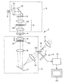
図4は本発明に基づく1実施例の倒立型顕微鏡の概略光路図であり、この倒立顕微鏡1は、光源2と、光源2から発せられた光を導くための照明光学系3と、観察物体4の像を形成するための観察光学系5と、観察物体4の像を拡大して目視観察するための接眼レンズ6と、観察物体4の像を撮像するための撮像素子7を有するCCDカメラ8とから構成されている。また、CCDカメラ8には、撮像された画像を記憶し演算処理するパソコン21とテレビモニター22とが接続されている。
FIG. 4 is a schematic optical path diagram of an inverted microscope according to an embodiment of the present invention. The
照明光学系3は、光源2側から順に、コレクターレンズ10、照明光の光軸11を偏向させるための偏向ミラー12、光源2からの光を準単色とするための干渉フィルタ13、及び、コンデンサレンズ14により構成されている。
The illumination
観察光学系5は、観察物体4側から順に、観察物体4の像を形成するための対物レンズ15、第1のリレーレンズ16、対物レンズ15からの光を偏向するための偏向ミラー17、第1のリレーレンズ16と共に対物レンズ15の像(観察物体4の像)を結像面に結像させるための第2のリレーレンズ18により構成されている。
The observation
また、第2のリレーレンズ18と結像面19との間には、観察物体4の像を接眼レンズ6による目視観察とCCDカメラ8による観察が同じ又は任意に切り換えることができるように、ハーフミラーである切り換えミラー20が配置されている。
In addition, between the
また、光源2からの光が投射されるコンデンサーレンズ14の瞳位置25には、図5(a)に示し円形開口26又は図5(b)に示す輪帯開口27を有する開口ユニット28が、着脱自在に配置されている。開口26及び27自体は、瞳の中心に対して同軸の状態になるように配置されている。また、開口ユニット28の開口26、27以外は、遮光性の遮光板から形成されている。
Further, at the
ここで、開口26、27は、図6(a)、(b)に対物レンズ15の瞳面30での像を示すように、対物レンズ15の瞳面30に開口像26’、27’として投影された状態で、対物レンズ15の瞳30’の直径をD0 、円形開口26の対物レンズ15の瞳面30での像26’の開口幅(直径)をD1 、輪帯開口27の対物レンズ15の瞳面30での像27’の開口幅をD1 とするとき、
D0 /10≦D1 ≦D0 /3 ・・・(10)
を満足することが望ましい。その意味は後記する。
Here, the
D 0/10 ≦ D 1 ≦ D 0/3 ··· (10)
It is desirable to satisfy The meaning will be described later.
さらに、対物レンズ15の瞳面30には、吸収膜ユニット31が、着脱自在に配置されている。吸収膜ユニット31には、開口ユニット28の開口の瞳面での像に対応する形状であってその形状より若干大きな形状の吸収膜が設けられている。すなわち、図7(a)、(b)に開口ユニット28の開口がそれぞれ円形開口26、輪帯開口27に対応する吸収膜ユニット31の吸収膜32、33の形状を示す。図7(a)、(b)に示すように、吸収膜ユニット31に設けられる吸収膜32、33の形状は、開口ユニット28の開口が円形開口26の場合は同様に円形であり、輪帯開口27の場合は同様に輪帯形状であり、しかも、開口ユニット28の開口26、27の対物レンズ15の瞳面30でのそれぞれの像26’、27’の開口幅より内外周辺に余裕幅Δだけ大きく形成されている。この余裕幅Δについては、
Δ≦D0 /10 ・・・(11)
を満足することが望ましい。その意味は後記する。
Further, an
Δ ≦ D 0/10 ··· ( 11)
It is desirable to satisfy The meaning will be described later.
この実施例はこのように構成されているので、光源2からの照明光は、コンデンサーレンズ14の瞳位置に投射される。そして、この照明光は、コンデンサーレンズ14によってケーラー照明として観察物体4を照明する。観察物体4を照明した光は、観察物体4を透過して対物レンズ15に入射する。対物レンズ15に入射した光は、対物レンズ15と第1のリレーレンズ16及び第2のリレーレンズ18により結像面19に観察物体4の像を形成する。結像面19に形成された観察物体4の像は、接眼レンズ6に入射すると共に、切り換えミラー20により、CCDカメラ8の撮像素子7の撮像面上に結像する。したがって、合焦位置で観察物体4の通常の顕微鏡観察ができる。
Since this embodiment is configured in this manner, the illumination light from the
一方、開口ユニット28をコンデンサーレンズ14の瞳位置に配置した場合、開口ユニット28の円形開口26の像26’又は輪帯開口27の像27’は、対物レンズ15の瞳面30に、図6に示すように、その瞳30’と同軸になるように投影される。
On the other hand, when the
ここで、開口ユニット28の円形開口26又は輪帯開口27を通った照明光は、観察物体4である例えば培養される立体的な大きさを持った生体細胞に入射され、透過光、屈折光、及び、回折光に分解されて細胞から射出する。細胞の輪郭が球や楕円体に近い形状をしている部分の場合は、屈折する光が多くなり、扁平な部分の場合は透過光と回折光が多くなる。細胞の球や楕円体に近い部分で屈折した光は、一部の光が対物レンズ15のNAより大きくなり、対物レンズ15には取り込まれない。
Here, the illumination light that has passed through the
この実施例では、対物レンズ15の光軸方向の位置を、顕微鏡に付属する焦準機構(焦点調節機構)を調節して通常の観察の合焦位置とされている位置から観察物体4に対し前後何れかに微小量だけ移動させてデフォーカスさせる。デフォーカスを与えると、開口ユニット28の円形開口26又は輪帯開口27を通った照明光は、観察物体4で回折した光とそれを透過した光が、対物レンズ15の瞳30’内の異なる部分を通過する(図3参照)。透過光束と回折光束の間には、回折角とデフォーカスに基づく波面の変化量に対応した位相差が生じる。この位相差は、位相差顕微鏡の位相膜と同様の作用をし、観察物体4の位相分布に比例した像強度分布を結像面19上に形成する。
In this embodiment, the position of the
対物レンズ15を前後に移動させる移動量は、形成される像にボケが生じない範囲であることが必要であり、観察に使用する光源2の波長を使用する対物レンズ15のNAの2乗で割った値以下であることが望ましい。
The amount of movement by which the
ところで、前記したように、対物レンズ15の瞳30’の直径D0 に対して、開口ユニット28の円形開口26の瞳面30での像26’又は輪帯開口27の像27’の開口幅(円形開口26の場合には直径)D1 は式(10)を満足することが望ましい。この点を説明すると、前記の式(6)から明らかなように、透過光と回折光が瞳30’内で重なる部分は、位相差量が0になり位相物体の像強度分布を発生させない。したがって、瞳30’の直径D0 に対して開口の像26’又は27’の開口幅が大きすぎると、式(6)の値が0に近づいてしまう。その上限は瞳30’の直径D0 の1/3程度である。
By the way, as described above, with respect to the diameter D 0 of the
逆に、開口の像26’又は27’の開口幅が小さすぎると、像観察に利用できる光量が不足して明るい像が観察できなくなる。その下限が瞳30’の直径D0 の1/10程度である。
Conversely, if the aperture width of the aperture image 26 'or 27' is too small, the amount of light available for image observation is insufficient and a bright image cannot be observed. The lower limit is about 1/10 of the diameter D 0 of the
ところで、本発明の位相物体の可視化の原理は、位相物体での0次透過光と±1次以上の回折光の干渉による結像の際に、透過光に対して回折光に位相差を与えることによって像強度分布に変換することである。そのため、透過光の振幅が相対的に大きすぎると、バックグラウンドが明るくなりすぎ、可視化される位相物体の像のコントラストが低下してしまう。しかし、透過光の振幅を選択的に低下させるようにすることにより、回折光と干渉して形成される像強度分布のコントラストを良くすることが可能になる。そこで、対物レンズ15の瞳面30に図7(a)、(b)で示しような吸収膜ユニット31を配置して、観察物体4で回折されずに透過する光の一部を吸収させるようにすることが望ましい。その際、吸収膜ユニット31に設けられる吸収膜32、33の形状を、式(11)を満たすように、開口26、27の像26’、27’の開口幅より内外周辺に余裕幅Δだけ大きくすることが望ましい。すなわち、透過光が対物レンズ15の瞳面30上に形成する開口26、27の像26’、27’の近傍は、観察物体4の位相分布での屈折面や反射面(後記するような反射型顕微鏡の場合)の勾配による光が主として入射する領域であり、開口26、27の像26’、27’の開口幅より内外周辺にD0 /10以下程度の余裕幅Δを持たせることにより、観察物体4で回折した光が形成する位相分布の像強度分布にほとんど影響を与えずに、この屈折又は反射による光の成分を効果的に減らすことができる。
By the way, the principle of visualization of the phase object according to the present invention is that a phase difference is given to the diffracted light with respect to the transmitted light at the time of image formation by interference of the 0th order transmitted light and the ± 1st order or more diffracted light on the phase object. It is to convert into an image intensity distribution. For this reason, when the amplitude of the transmitted light is relatively large, the background becomes too bright, and the contrast of the image of the phase object to be visualized is lowered. However, by selectively reducing the amplitude of the transmitted light, it is possible to improve the contrast of the image intensity distribution formed by interference with the diffracted light. Therefore, an
なお、このような効果を得るためには、吸収膜32、33の透過率は10%〜30%の範囲内にあることが望ましい。
In order to obtain such an effect, the transmittance of the
ところで、前記したように、デフォーカスによって生じる位相差は、観察物体4が対物レンズ15の合焦位置から近点側にずれた場合と遠点側にずれた場合で符号が変わる。そのため、培養細胞等の観察物体を対物レンズ15の合焦位置から近点側にずらして観察した画像と遠点側にずらして観察した画像は、観察物体4の位相分布に相当して夫々得られる画像の像コントラストが反転している。そこで、近点側にずらしてCCDカメラ8で撮像した画像と遠点側にずらして撮像した画像とをパソコン21に取り込んで、2つの画像の各画素毎に差演算を行うことにより、観察物体4の位相分布に相当する画像成分の像コントラストは2倍にすることができ、また、波面変化に影響されないゴミや異物、照明ムラ等の位相情報を持たない画像成分ハローの成分は相殺されて0になり、観察物体4の位相分布に対応した像強度分布のみを得ることができる。
By the way, as described above, the sign of the phase difference caused by defocusing changes depending on whether the
上記実施例では、対物レンズ15の瞳30’内で観察物体4で回折した光とそれを透過した光の間に位相差を発生させるのに、顕微鏡の焦準機構によるデフォーカスを利用していた。しかし、この回折光と透過光の間に位相差を対物レンズ15の瞳30’位置で導入するのに、デフォーカスでなく、可変形状ミラー(デフォーマブルミラー)を用いても可能であることは前記した。図8にその場合の図4と同様の図を示す。
In the above embodiment, defocusing by the focusing mechanism of the microscope is used to generate a phase difference between the light diffracted by the
この例の場合には、図4の偏向ミラー17の代わりに、可変形状ミラー17’を配置している点だけで図4の構成とは異なる。可変形状ミラー17’は第1のリレーレンズ16を介して対物レンズ15の瞳面30と共役な位置に配置してあり、この可変形状ミラー17’により、デフォーカスの場合と同様に、光軸を中心として半径の例えば2乗に比例する回転対称で可変な波面収差を発生させることにより、焦準機構によるデフォーカスと同様に、回折光と透過光の間に位相差を発生させて、観察物体4の位相分布に比例した像強度分布を結像面19上に形成することができる。なお、瞳面30での波面収差を回転対称に発生させるには、偏心配置の可変形状ミラー17’の変形をその偏心を補償するように非対称に発生させるようにすればよい。
In the case of this example, the configuration is different from that of FIG. 4 only in that a
この場合も、回折光と透過光の間の角度が変わると、可変形状ミラー17’の同じ変形量でも2つの光束の間に発生する位相差量が異なってくるので、観察する例えば細胞毎にその変形量変えることにより、より良い像コントラストを得ることができる。
In this case as well, if the angle between the diffracted light and the transmitted light changes, the amount of phase difference generated between the two light beams varies even with the same deformation amount of the
そして、可変形状ミラー17’の変形によって生じる各光線の位相差は、可変形状ミラー17’の変形が対物レンズ15側にずれた場合と接眼レンズ6側にずれた場合で符号が変わる。そのため、培養細胞等の観察物体4を可変形状ミラー17’の変形を対物レンズ15側にずらして観察した画像と接眼レンズ6側にずらして観察した画像は、観察物体4の位相分布に相当して夫々得られる画像の像コントラストが反転しているものとなる。
The sign of the phase difference of each light beam caused by the deformation of the
この実施例においても、図4の実施例と同様に、対物レンズ15の瞳面30に吸収膜ユニット31を配置して、観察物体4の0次透過光を一部吸収させることにより、可視化される位相物体の像のコントラストを向上させるようにすることができる。
Also in this embodiment, similarly to the embodiment of FIG. 4, the
なお、この実施例の場合にも、式(10)、式(11)を満たすようにすることが望ましい。 In the case of this embodiment as well, it is desirable to satisfy the expressions (10) and (11).
なお、対物レンズ15の瞳面30に吸収膜ユニット31を配置する代わりに、可変形状ミラー17’がこの瞳面30と共役位置に配置されることを利用して、可変形状ミラー17’の反射面に吸収膜32又は33と同様の形状(第1のリレーレンズ16による瞳30’の像の結像倍率が等倍でない場合には、吸収膜32、33の形状にその倍率を掛けた相似形の形状)の吸収膜を設けるようにしても同様の効果が得られる。ただし、反射面の表面に設けた吸収膜は2度透過するので、その吸収膜の透過率は概ね2倍の20%〜60%の範囲のものとするのが望ましい。
In addition, instead of disposing the
図4の実施例に対して図8の実施例の場合は、可変形状ミラー17’の変形の制御が対物レンズ15の焦準制御に比較して高速にできるので、位相分布の可視化を高速にでき、リアルタイム化が可能になる。
In the case of the embodiment of FIG. 8 in contrast to the embodiment of FIG. 4, the deformation control of the
ところで、図4の実施例も図8の実施例も、照明用の光源2としては、ハロゲンランプ等の面積のある光源を前提としていた。これに対して、図9に示す実施例は、照明用の光源としてLED2’を用いることを前提としている。LED2’は実質的に単色で発散光を出す略点光源とみなせるため、この実施例においては、照明光学系3としては、コレクターレンズ10、照明光の光軸11を偏向させるための偏向ミラー12、及び、コンデンサレンズ14により構成しており、LED2’からの光をコンデンサーレンズ14の瞳位置25に結像するように構成している。
Incidentally, both the embodiment of FIG. 4 and the embodiment of FIG. 8 are based on the assumption that the
そして、図4の実施例と異なる他の点は、コンデンサーレンズ14の瞳位置25に開口ユニット28、すなわち、円形開口26や輪帯開口27を配置しない点であり、その他は、図4の場合と同様である。
4 is that the
その理由は、LED2’は略点光源とみなせるため、コンデンサーレンズ14の瞳位置25に結像されたLED2’の像も点光源とみなすことができ、そのLED2’の像の輪郭が開口26、27と等価の役割をする。そして、LED2’の対物レンズ15の瞳30’中に結像される像も略点とみなすことができるため、観察物体4を透過した光と回折された光とは瞳30’内でほとんど重ならないので、効率良く位相物体の像強度分布を発生させるのに寄与する。しかも、LED2’から発散されてコレクターレンズ10に取り込まれた光は略全て観察物体4の照明に利用されるため、明るい像が観察できる。なお、LED2’のコンデンサーレンズ14の瞳位置25への結像は、縮小倍率で結像されるように構成することが望ましい。その理由は、LED2’からの発散光束の発散角を大きくなるように変換して広い観察物体面を照明できるようになると共に、対物レンズ15の瞳30’中に結像されるLED2’の像をより小さく結像させることができるようになるからである。
The reason is that since the
この実施例においては、吸収膜ユニット31に設ける吸収膜の形状としては、瞳30’内でのLED2’の像に対応した形状であって、式(11)を満たすような余裕幅Δをその周囲に持たせたものとすることが望ましい。
In this embodiment, the shape of the absorption film provided in the
なお、この実施例においても、位相分布を可視化するのに、顕微鏡の焦準機構によるデフォーカスに代えて、図8の実施例のように、図9の偏向ミラー17の代わりに対物レンズ15の瞳面30と共役な位置に可変形状ミラー17’を配置し、その可変形状ミラー17’のミラー形状の変形を利用するようにしてもよい。
In this embodiment as well, in order to visualize the phase distribution, instead of defocusing by the focusing mechanism of the microscope, the
ところで、本発明に基づく顕微鏡は、金属顕微鏡等の反射型顕微鏡の場合にも適用できる。本発明の原理によって可視化する位相分布の例としては、半導体基板や金属基板上に形成された微細な凹凸の観察がある。 By the way, the microscope based on this invention is applicable also in the case of reflection type microscopes, such as a metal microscope. As an example of the phase distribution visualized by the principle of the present invention, there is observation of fine irregularities formed on a semiconductor substrate or a metal substrate.
図10に、図4の形態を反射型顕微鏡にした場合の概略光路図を示す。この反射型顕微鏡1’は、光源2と、光源2から発せられた光を導くための照明光学系3と、観察物体4の像を形成するための観察光学系5と、観察物体4の像を拡大して目視観察するための接眼レンズ6と、観察物体4の像を撮像するための撮像素子7を有するCCDカメラ8とから構成されている。また、CCDカメラ8には、撮像された画像を記憶し演算処理するパソコン21とテレビモニター22とが接続されている。
FIG. 10 shows a schematic optical path diagram when the configuration of FIG. 4 is a reflection microscope. The
照明光学系3は、光源2側から順に、コレクターレンズ10、照明光の光軸11を偏向させるための偏向ミラー12、光源2を準単色とするための干渉フィルタ13、及び、コンデンサレンズ14により構成されている。
The illumination
観察光学系5は、観察物体4側から順に、観察物体4の像を形成するための対物レンズ15、照明光学系3からの照明光を導入するハーフミラー37、第1のリレーレンズ16、対物レンズ15からの光を偏向するための偏向ミラー17、第2の偏向ミラー38、第1のリレーレンズ16と共に対物レンズ15の像(観察物体4の像)を結像面に結像させるための第2のリレーレンズ18により構成されている。
The observation
また、第2のリレーレンズ18と結像面19との間には、観察物体4の像を接眼レンズ6による目視観察とCCDカメラ8による観察が同じ又は任意に切り換えることができるように、ハーフミラーである切り換えミラー20が配置されている。
In addition, between the
また、光源2からの光が投射されるコンデンサーレンズ14の瞳位置25には、図4の実施例と同様の開口ユニット28が、着脱自在に配置されている。
An
さらに、対物レンズ15の瞳面30には、図4の実施例と同様の吸収膜ユニット31が、着脱自在に配置されている。
Further, an
この実施例においては、光源2からの照明光は、コンデンサーレンズ14の瞳位置に投射される。そして、この照明光は、コンデンサーレンズ14を通り、ハーフミラー37で反射され、対物レンズ15を介してケーラー照明として観察物体4を落射照明する。観察物体4を照明した光は、観察物体4で反射されて対物レンズ15に入射する。対物レンズ15に入射した光はハーフミラー37を透過し、この対物レンズ15と第1のリレーレンズ16及び第2のリレーレンズ18により、結像面19に観察物体4の像を形成する。
In this embodiment, the illumination light from the
結像面19に形成された観察物体4の像は、接眼レンズ6に入射すると共に、切り換えミラー20により、CCDカメラ8の撮像素子7の撮像面上に結像する。したがって、合焦位置で観察物体4の通常の反射顕微鏡観察ができる。
The image of the
一方、開口ユニット28をコンデンサーレンズ14の瞳位置に配置した場合、光源2からの照明光は、コレクターレンズ10、干渉フィルタ13、及び、コンデンサレンズ14を構成する前側レンズ35を順に経て、開口ユニット28の円形開口26又は輪帯開口27を照明し、その円形開口26又は輪帯開口27を通過した光は、コンデンサレンズ14を構成する後側レンズ36とハーフミラー37を経て、対物レンズ15の瞳面30にそれらの像26’又は27’を結像し、その後対物レンズ15を経て観察物体4をコリメート光で落射照明し、観察物体4で反射された光と回折された光は再度対物レンズ15に入射して、その反射光は対物レンズ15の瞳面30に開口26又は27の像26’又は27’を再度結像する。
On the other hand, when the
したがって、この実施例においても、対物レンズ15の光軸方向の位置を、顕微鏡に付属する焦準機構(焦点調節機構)を調節して通常の観察の合焦位置とされている位置から観察物体4に対し前後何れかに微小量だけ移動させてデフォーカスさせると、開口ユニット28の円形開口26又は輪帯開口27を通った照明光は、観察物体4で回折した光とそれで反射した光が、対物レンズ15の瞳30’内の異なる部分を通過する(図3参照)。反射光束と回折光束の間には、回折角とデフォーカスに基づく波面の変化量に対応した位相差が生じる。この位相差は、観察物体4の凹凸量に比例した像強度分布を結像面19上に形成することになる。
Therefore, also in this embodiment, the object in the optical axis direction of the
この反射型顕微鏡においても、図4の実施例と同様に、対物レンズ15の瞳面30に吸収膜ユニット31を配置して、観察物体4の0次透過光を一部吸収させることにより、可視化される凹凸量に関する像のコントラストを向上させるようにすることができる。
Also in this reflection microscope, as in the embodiment of FIG. 4, the
なお、この実施例の場合にも、式(10)、式(11)を満たすようにすることが望ましい。 In the case of this embodiment as well, it is desirable to satisfy the expressions (10) and (11).
なお、対物レンズ15とハーフミラー37の間のに瞳面30に吸収膜ユニット31を配置すると、開口26又は27を経た照明光の強度全体を落射照明の際に弱めてしまうので、ハーフミラー37と結像面19の間の瞳面30に共役な位置に吸収膜ユニット31を配置するようにしてもよい。
If the
この反射型顕微鏡の場合も、図8の実施例と同様に、位相分布を可視化するのに、顕微鏡の焦準機構によるデフォーカスに代えて、図10の偏向ミラー17の代わりに対物レンズ15の瞳面30と共役な位置に可変形状ミラー17’を配置し、その可変形状ミラー17’のミラー形状の変形を利用するようにしてもよい。
Also in the case of this reflection microscope, as in the embodiment of FIG. 8, in order to visualize the phase distribution, instead of the defocusing by the focusing mechanism of the microscope, the
また、図9の実施例と同様に、光源2の代わりにLED2’を用い、コンデンサーレンズ14の瞳位置25に開口ユニット28を配置しないようにしてもよい。
Similarly to the embodiment of FIG. 9, the
なお、図4以外の実施例の場合も、対物レンズ15の瞳面30あるいはそれと共役な位置に導入する波面収差を反転させることにより像強度分布のコントラストを反転させることができるので、図4の実施例と同様に、CCDカメラ8でコントラストを反転させる前の画像と反転させた画像とをCCDカメラ8で撮像してパソコン21に取り込み、その2つの画像の各画素毎に差演算を行うことにより、観察物体4の位相分布又は凹凸分布に相当する画像成分の像コントラストは2倍にすることができ、また、波面変化に影響されないゴミや異物、照明ムラ等の位相情報を持たない画像成分ハローの成分は相殺されて0になり、観察物体4の位相分布又は凹凸分布に対応した像強度分布のみを得ることができる。
In the case of the embodiments other than FIG. 4, the contrast of the image intensity distribution can be reversed by inverting the wavefront aberration introduced to the
以上から明らかなように、本発明の顕微鏡観察方法及びそれを用いるための顕微鏡に基づくと、位相差顕微鏡や微分干渉顕微鏡を用いなくても、生体細胞や金属表面等の微小な凹凸を観察することができる。特に、従来の位相差顕微鏡や微分干渉顕微鏡で困難であった結像倍率4倍以下の比較的低倍率における位相分布や凹凸分布の観察が可能になる。また、照明ムラやハロー成分を相殺することができ、観察物体の位相分布や凹凸分布に対応したコントラストの良い像強度分布を得ることができる。 As is clear from the above, based on the microscope observation method of the present invention and the microscope for using the same, it is possible to observe minute irregularities such as living cells and metal surfaces without using a phase contrast microscope or a differential interference microscope. be able to. In particular, it is possible to observe the phase distribution and uneven distribution at a relatively low magnification of 4 times or less, which has been difficult with conventional phase contrast microscopes and differential interference microscopes. Further, illumination unevenness and halo components can be offset, and an image intensity distribution with good contrast corresponding to the phase distribution and uneven distribution of the observation object can be obtained.
以上、本発明の顕微鏡観察方法及びそれを用いるための顕微鏡をその原理と実施例に基づいて説明してきたが、これら実施例に限定されず種々の変形が可能である。 As mentioned above, although the microscope observation method of the present invention and the microscope for using the same have been described based on the principle and the examples, the invention is not limited to these examples, and various modifications are possible.
1…倒立顕微鏡
1’…反射型顕微鏡
2…光源
2’…LED
3…照明光学系
4…観察物体
5…観察光学系
6…接眼レンズ
7…撮像素子
8…CCDカメラ
10…コレクターレンズ
11…照明光の光軸
12…偏向ミラー
13…干渉フィルタ
14…コンデンサレンズ
15…対物レンズ
16…第1のリレーレンズ
17…偏向ミラー
17’…可変形状ミラー
18…第2のリレーレンズ
19…結像面
20…切り換えミラー
21…パソコン
22…テレビモニター
25…コンデンサーレンズの瞳位置
26…円形開口
26’…円形開口の像
27…輪帯開口
27’…輪帯開口の像
28…開口ユニット
30…対物レンズの瞳面
30’…対物レンズの瞳
31…吸収膜ユニット
32…円形開口に対応する吸収膜
33…輪帯開口に対応する吸収膜
35…コンデンサレンズの前側レンズ
36…コンデンサレンズの後側レンズ
37…ハーフミラー
38…第2の偏向ミラー
DESCRIPTION OF
DESCRIPTION OF
Claims (10)
前記結像光学系の瞳位置での前記部分開口の像の形状に対応する形状であって、その形状より若干大きな形状の吸収膜を、前記結像光学系の瞳又はそれと共役な位置近傍に配置し、前記結像光学系の瞳位置での前記部分開口の像に対する前記吸収膜の内外周辺での余裕幅をΔとし、前記結像光学系の瞳の直径をD 0 とするとき、
Δ≦D 0 /10 ・・・(11)
を満足することを特徴とする顕微鏡観察方法。 A partial aperture is arranged at the pupil position of the illumination optical system of the microscope, and an observation object having a phase distribution is illuminated by the light passing through the partial aperture, and the diameter of the image at the pupil position of the imaging optical system of the partial aperture is The observation object is set to be smaller than the diameter of the pupil of the imaging optical system, and wavefront aberration is introduced by means for causing a deviation from the in-focus position of the imaging optical system. Form an image on the image plane, observe an image proportional to the phase distribution ,
An absorption film having a shape corresponding to the shape of the image of the partial aperture at the pupil position of the imaging optical system and slightly larger than that shape is placed near the pupil of the imaging optical system or a position conjugate with it. And when the margin width at the inner and outer periphery of the absorption film with respect to the image of the partial aperture at the pupil position of the imaging optical system is Δ and the diameter of the pupil of the imaging optical system is D 0 ,
Δ ≦ D 0/10 ··· ( 11)
A microscope observation method characterized by satisfying
前記結像光学系の瞳位置での前記略点光源の像の形状に対応する形状であって、その形状より若干大きな形状の吸収膜を、前記結像光学系の瞳又はそれと共役な位置近傍に配置し、前記結像光学系の瞳位置での前記略点光源の像に対する前記吸収膜の内外周辺での余裕幅をΔとし、前記結像光学系の瞳の直径をD 0 とするとき、
Δ≦D 0 /10 ・・・(11)
を満足することを特徴とする顕微鏡観察方法。 Using an approximate point light source that emits divergent light as an illumination light source, an image of the approximate point light source is formed at the pupil position of the illumination optical system of the microscope, and an observation object having a phase distribution by diverging light from the image of the approximate point light source The diameter of the image at the pupil position of the imaging optical system of the substantially point light source is set smaller than the diameter of the pupil of the imaging optical system, and is deviated from the in-focus position of the imaging optical system. Introducing wavefront aberration by means for generating an image of the observation object on the imaging surface of the imaging optical system, observing an image proportional to the phase distribution ,
An absorption film corresponding to the shape of the image of the substantially point light source at the pupil position of the imaging optical system and having a slightly larger shape than the pupil of the imaging optical system or near a position conjugate to the pupil arranged, the margin width in and out around the absorbent layer to the image of the substantially point light source at the pupil position of the imaging optical system and delta, the pupil diameter of said image forming optical system when the D 0 ,
Δ ≦ D 0/10 ··· ( 11)
A microscope observation method characterized by satisfying
D0 /10≦D1 ≦D0 /3 ・・・(10)
を満足することを特徴とする請求項1に記載の顕微鏡観察方法。 When the partial aperture is a circular aperture or an annular aperture, the aperture width of the image at the pupil position of the imaging optical system is D 1 , and the diameter of the pupil of the imaging optical system is D 0 ,
D 0/10 ≦ D 1 ≦ D 0/3 ··· (10)
The microscope observation method according to claim 1 , wherein:
前記部分開口の前記結像光学系の瞳位置での像の径は、前記結像光学系の瞳の径より小さく設定されており、かつ、前記結像光学系の合焦位置からずれを生じさせる手段を備え、
前記接眼光学系又は前記撮像光学系により前記位相分布に比例した像を観察可能であり、
前記結像光学系の瞳位置での前記部分開口の像の形状に対応する形状であって、その形状より若干大きな形状の吸収膜が、前記結像光学系の瞳又はそれと共役な位置近傍に配置されており、前記結像光学系の瞳位置での前記部分開口の像に対する前記吸収膜の内外周辺での余裕幅をΔとし、前記結像光学系の瞳の直径をD 0 とするとき、
Δ≦D 0 /10 ・・・(11)
を満足することを特徴とする顕微鏡。 A light source, an illumination optical system that guides light from the light source to an observation object having a phase distribution, a partial aperture disposed at a substantially pupil position of the illumination optical system, and the light illuminated by the light that has passed through the partial aperture An imaging optical system that forms an image of an observation object on an imaging plane; and a microscope that includes an eyepiece optical system or an imaging optical system for observing an image formed on the imaging plane.
The diameter of the image of the partial aperture at the pupil position of the imaging optical system is set smaller than the diameter of the pupil of the imaging optical system, and a deviation occurs from the in-focus position of the imaging optical system. Means to
Wherein Ri observable der an image which is proportional to the phase distribution by the eyepiece optical system or the imaging optical system,
An absorption film having a shape corresponding to the shape of the image of the partial aperture at the pupil position of the imaging optical system and slightly larger than that shape is located in the vicinity of the pupil of the imaging optical system or a conjugate position thereof. are arranged, the margin width in and out around the absorbent layer to the image of the partial aperture at the pupil position of the imaging optical system and delta, the pupil diameter of said image forming optical system when the D 0 ,
Δ ≦ D 0/10 ··· ( 11)
A microscope characterized by satisfying
前記略点光源の前記結像光学系の瞳位置での像の径は、前記結像光学系の瞳の径より小さく設定されており、かつ、前記結像光学系の合焦位置からずれを生じさせる手段を備え、
前記接眼光学系又は前記撮像光学系により前記位相分布に比例した像を観察可能であり、
前記結像光学系の瞳位置での前記略点光源の像の形状に対応する形状であって、その形状より若干大きな形状の吸収膜が、前記結像光学系の瞳又はそれと共役な位置近傍に配置されており、前記結像光学系の瞳位置での前記略点光源の像に対する前記吸収膜の内外周辺での余裕幅をΔとし、前記結像光学系の瞳の直径をD 0 とするとき、
Δ≦D 0 /10 ・・・(11)
を満足することを特徴とする顕微鏡。 From an approximate point light source that emits divergent light, an illumination optical system that forms an image of the approximate point light source once at the pupil position and guides the light from the approximate point light source to an observation object having a phase distribution, and the approximate point light source An eyepiece optical system or an imaging optical system for observing the image formed on the imaging surface. In the microscope equipped,
The diameter of the image at the pupil position of the imaging optical system of the substantially point light source is set smaller than the diameter of the pupil of the imaging optical system, and is shifted from the in-focus position of the imaging optical system. With means to generate ,
Wherein Ri observable der an image which is proportional to the phase distribution by the eyepiece optical system or the imaging optical system,
An absorption film having a shape corresponding to the shape of the image of the substantially point light source at the pupil position of the imaging optical system and having a slightly larger shape than the pupil, or near a position conjugate with the pupil of the imaging optical system And Δ is a margin width in the periphery of the absorption film with respect to the image of the substantially point light source at the pupil position of the imaging optical system, and D 0 is the diameter of the pupil of the imaging optical system. and when,
Δ ≦ D 0/10 ··· ( 11)
A microscope characterized by satisfying
D0 /10≦D1 ≦D0 /3 ・・・(10)
を満足することを特徴とする請求項6に記載の顕微鏡。 When the partial aperture is a circular aperture or an annular aperture, the aperture width of the image at the pupil position of the imaging optical system is D 1 , and the diameter of the pupil of the imaging optical system is D 0 ,
D 0/10 ≦ D 1 ≦ D 0/3 ··· (10)
The microscope according to claim 6 , wherein:
Priority Applications (3)
| Application Number | Priority Date | Filing Date | Title |
|---|---|---|---|
| JP2003414158A JP4582762B2 (en) | 2003-12-12 | 2003-12-12 | Microscope observation method and microscope for using the same |
| US11/003,728 US7564622B2 (en) | 2003-12-12 | 2004-12-06 | Methods for implement microscopy and microscopic measurement as well as microscope and apparatus for implementing them |
| US12/386,091 US20090201580A1 (en) | 2003-12-12 | 2009-04-13 | Methods for implement microscopy and microscopic measurement as well as microscope and apparatus for implementing them |
Applications Claiming Priority (1)
| Application Number | Priority Date | Filing Date | Title |
|---|---|---|---|
| JP2003414158A JP4582762B2 (en) | 2003-12-12 | 2003-12-12 | Microscope observation method and microscope for using the same |
Publications (3)
| Publication Number | Publication Date |
|---|---|
| JP2005173288A JP2005173288A (en) | 2005-06-30 |
| JP2005173288A5 JP2005173288A5 (en) | 2007-01-18 |
| JP4582762B2 true JP4582762B2 (en) | 2010-11-17 |
Family
ID=34734043
Family Applications (1)
| Application Number | Title | Priority Date | Filing Date |
|---|---|---|---|
| JP2003414158A Expired - Fee Related JP4582762B2 (en) | 2003-12-12 | 2003-12-12 | Microscope observation method and microscope for using the same |
Country Status (1)
| Country | Link |
|---|---|
| JP (1) | JP4582762B2 (en) |
Families Citing this family (12)
| Publication number | Priority date | Publication date | Assignee | Title |
|---|---|---|---|---|
| CN101278190B (en) | 2005-09-29 | 2012-12-19 | 奥林巴斯株式会社 | Focal position determining method, focal position determining apparatus, feeble light detecting apparatus and feeble light detecting method |
| JP5307539B2 (en) * | 2006-05-31 | 2013-10-02 | オリンパス株式会社 | Biological sample imaging method and biological sample imaging apparatus |
| JP5132480B2 (en) | 2008-08-26 | 2013-01-30 | オリンパス株式会社 | microscope |
| JP5814684B2 (en) * | 2010-09-03 | 2015-11-17 | オリンパス株式会社 | Phase object visualization method and visualization apparatus |
| JP5201185B2 (en) * | 2010-09-14 | 2013-06-05 | オムロン株式会社 | Observation optical system and laser processing apparatus |
| JP5757458B2 (en) * | 2011-04-12 | 2015-07-29 | 株式会社ニコン | Microscope system, server and program |
| JP2013161073A (en) * | 2012-02-09 | 2013-08-19 | Topcon Corp | Wavelength selection optical element, microscope using the wavelength selection optical element, and digital camera using the wavelength selection optical element |
| EP2963475A4 (en) | 2013-02-28 | 2016-10-26 | Olympus Corp | Specimen observation method and specimen observation device |
| JP6381437B2 (en) | 2014-12-24 | 2018-08-29 | オリンパス株式会社 | Phase contrast microscope |
| JP6546989B2 (en) * | 2015-05-20 | 2019-07-17 | オリンパス株式会社 | Sample observing apparatus and sample observing method |
| JP6797564B2 (en) | 2016-06-01 | 2020-12-09 | オリンパス株式会社 | Phase object visualization device, phase object visualization method |
| WO2018198335A1 (en) * | 2017-04-28 | 2018-11-01 | オリンパス株式会社 | Sample observation device |
Citations (11)
| Publication number | Priority date | Publication date | Assignee | Title |
|---|---|---|---|---|
| JPH07225341A (en) * | 1993-12-17 | 1995-08-22 | Olympus Optical Co Ltd | Phase contrast microscope |
| JPH085929A (en) * | 1994-06-17 | 1996-01-12 | Olympus Optical Co Ltd | Microscope optical system |
| JPH0815612A (en) * | 1994-07-01 | 1996-01-19 | Olympus Optical Co Ltd | Microscope device |
| JPH08502600A (en) * | 1992-10-30 | 1996-03-19 | ライカ ミクロスコピー ウント ジュステーメ ゲーエムベーハー | Method and device for contrasting object to be inspected by microscope |
| JPH0990254A (en) * | 1995-09-25 | 1997-04-04 | Asahi Optical Co Ltd | Scanning optical system |
| JPH09179029A (en) * | 1995-12-26 | 1997-07-11 | Olympus Optical Co Ltd | Phase difference microscope |
| JPH1184260A (en) * | 1997-09-11 | 1999-03-26 | Olympus Optical Co Ltd | Phase-contrast microscope |
| JP2000098253A (en) * | 1998-09-22 | 2000-04-07 | Olympus Optical Co Ltd | Device for detecting physycal quantity of observed object and detecting method using the same |
| JP2001075009A (en) * | 1999-09-07 | 2001-03-23 | Olympus Optical Co Ltd | Optical device and microscope |
| JP2002328295A (en) * | 2001-04-27 | 2002-11-15 | Olympus Optical Co Ltd | Focus detector and optical microscope or optical inspection apparatus having the same |
| JP2003121749A (en) * | 2001-08-09 | 2003-04-23 | Olympus Optical Co Ltd | Microscope |
-
2003
- 2003-12-12 JP JP2003414158A patent/JP4582762B2/en not_active Expired - Fee Related
Patent Citations (11)
| Publication number | Priority date | Publication date | Assignee | Title |
|---|---|---|---|---|
| JPH08502600A (en) * | 1992-10-30 | 1996-03-19 | ライカ ミクロスコピー ウント ジュステーメ ゲーエムベーハー | Method and device for contrasting object to be inspected by microscope |
| JPH07225341A (en) * | 1993-12-17 | 1995-08-22 | Olympus Optical Co Ltd | Phase contrast microscope |
| JPH085929A (en) * | 1994-06-17 | 1996-01-12 | Olympus Optical Co Ltd | Microscope optical system |
| JPH0815612A (en) * | 1994-07-01 | 1996-01-19 | Olympus Optical Co Ltd | Microscope device |
| JPH0990254A (en) * | 1995-09-25 | 1997-04-04 | Asahi Optical Co Ltd | Scanning optical system |
| JPH09179029A (en) * | 1995-12-26 | 1997-07-11 | Olympus Optical Co Ltd | Phase difference microscope |
| JPH1184260A (en) * | 1997-09-11 | 1999-03-26 | Olympus Optical Co Ltd | Phase-contrast microscope |
| JP2000098253A (en) * | 1998-09-22 | 2000-04-07 | Olympus Optical Co Ltd | Device for detecting physycal quantity of observed object and detecting method using the same |
| JP2001075009A (en) * | 1999-09-07 | 2001-03-23 | Olympus Optical Co Ltd | Optical device and microscope |
| JP2002328295A (en) * | 2001-04-27 | 2002-11-15 | Olympus Optical Co Ltd | Focus detector and optical microscope or optical inspection apparatus having the same |
| JP2003121749A (en) * | 2001-08-09 | 2003-04-23 | Olympus Optical Co Ltd | Microscope |
Also Published As
| Publication number | Publication date |
|---|---|
| JP2005173288A (en) | 2005-06-30 |
Similar Documents
| Publication | Publication Date | Title |
|---|---|---|
| US10108008B2 (en) | Image-forming optical system, illumination apparatus, and observation apparatus | |
| US20090201580A1 (en) | Methods for implement microscopy and microscopic measurement as well as microscope and apparatus for implementing them | |
| US9360665B2 (en) | Confocal optical scanner | |
| JP3563800B2 (en) | Observation optical device | |
| JP4582762B2 (en) | Microscope observation method and microscope for using the same | |
| JP4917404B2 (en) | Phase object visualization method and microscope system | |
| JP4222877B2 (en) | Microscope observation method and microscope used therefor | |
| US10330905B2 (en) | Pair of phase modulation elements for imaging optical system, imaging optical system, illuminating device, and microscope apparatus | |
| US20170192217A1 (en) | Optical-axis-direction scanning microscope apparatus | |
| US20170205611A1 (en) | Imaging optical system, illuminating device, and microscope apparatus | |
| JP4149309B2 (en) | Scanning optical microscope | |
| US20170205609A1 (en) | Image-forming optical system, illumination apparatus, and microscope apparatus | |
| JP4689171B2 (en) | Method and apparatus for measuring state of cultured cells | |
| JP2011085432A (en) | Axial chromatic aberration optical system and three-dimensional shape measuring device | |
| JP5929204B2 (en) | Scanning microscope | |
| US20220244516A1 (en) | Microscope device and data generation method using microscope | |
| JP2004318185A (en) | Optical microscope having light control member | |
| JP6381437B2 (en) | Phase contrast microscope | |
| US20150185486A1 (en) | Holographic imaging element operable to generate multiple different images of an object | |
| JP4940841B2 (en) | Modulation contrast microscope | |
| Chmelik et al. | Quantitative phase imaging in turbid media by coherence controlled holographic microscopy | |
| JP2008185719A (en) | Microscope device | |
| JP2013097132A (en) | Imaging device | |
| WO2023248459A1 (en) | Microscope device and data generation method | |
| US10884230B2 (en) | Phase object visualization apparatus and phase object visualization method |
Legal Events
| Date | Code | Title | Description |
|---|---|---|---|
| A521 | Written amendment |
Free format text: JAPANESE INTERMEDIATE CODE: A523 Effective date: 20061122 |
|
| A621 | Written request for application examination |
Free format text: JAPANESE INTERMEDIATE CODE: A621 Effective date: 20061122 |
|
| A977 | Report on retrieval |
Free format text: JAPANESE INTERMEDIATE CODE: A971007 Effective date: 20100301 |
|
| A131 | Notification of reasons for refusal |
Free format text: JAPANESE INTERMEDIATE CODE: A131 Effective date: 20100331 |
|
| A521 | Written amendment |
Free format text: JAPANESE INTERMEDIATE CODE: A523 Effective date: 20100526 |
|
| A131 | Notification of reasons for refusal |
Free format text: JAPANESE INTERMEDIATE CODE: A131 Effective date: 20100616 |
|
| A521 | Written amendment |
Free format text: JAPANESE INTERMEDIATE CODE: A523 Effective date: 20100803 |
|
| TRDD | Decision of grant or rejection written | ||
| A01 | Written decision to grant a patent or to grant a registration (utility model) |
Free format text: JAPANESE INTERMEDIATE CODE: A01 Effective date: 20100825 |
|
| A01 | Written decision to grant a patent or to grant a registration (utility model) |
Free format text: JAPANESE INTERMEDIATE CODE: A01 |
|
| A61 | First payment of annual fees (during grant procedure) |
Free format text: JAPANESE INTERMEDIATE CODE: A61 Effective date: 20100830 |
|
| R151 | Written notification of patent or utility model registration |
Ref document number: 4582762 Country of ref document: JP Free format text: JAPANESE INTERMEDIATE CODE: R151 |
|
| FPAY | Renewal fee payment (event date is renewal date of database) |
Free format text: PAYMENT UNTIL: 20130910 Year of fee payment: 3 |
|
| S531 | Written request for registration of change of domicile |
Free format text: JAPANESE INTERMEDIATE CODE: R313531 |
|
| R350 | Written notification of registration of transfer |
Free format text: JAPANESE INTERMEDIATE CODE: R350 |
|
| R250 | Receipt of annual fees |
Free format text: JAPANESE INTERMEDIATE CODE: R250 |
|
| LAPS | Cancellation because of no payment of annual fees |