JP4580811B2 - Wireless data communication system - Google Patents
Wireless data communication system Download PDFInfo
- Publication number
- JP4580811B2 JP4580811B2 JP2005123276A JP2005123276A JP4580811B2 JP 4580811 B2 JP4580811 B2 JP 4580811B2 JP 2005123276 A JP2005123276 A JP 2005123276A JP 2005123276 A JP2005123276 A JP 2005123276A JP 4580811 B2 JP4580811 B2 JP 4580811B2
- Authority
- JP
- Japan
- Prior art keywords
- wireless
- relay
- repeater
- unit
- station
- Prior art date
- Legal status (The legal status is an assumption and is not a legal conclusion. Google has not performed a legal analysis and makes no representation as to the accuracy of the status listed.)
- Expired - Fee Related
Links
Images


Landscapes
- Radio Relay Systems (AREA)
- Telephonic Communication Services (AREA)
- Small-Scale Networks (AREA)
- Mobile Radio Communication Systems (AREA)
Description
本発明は、センター側装置に公衆電話回線等の通信回線を介して接続された端末側網制御装置と、ガスメータ、水道メータ、センサ等の端末機器との間でのデータ伝送を無線によって行う無線テレメータシステム、あるいは、端末装置からセンター側装置に異常事態を通報するセキュリティシステム等の無線データ通信システムに関する。 The present invention wirelessly performs data transmission between a terminal-side network control device connected to a center-side device via a communication line such as a public telephone line and terminal devices such as a gas meter, a water meter, and a sensor. The present invention relates to a radio data communication system such as a telemeter system or a security system for reporting an abnormal situation from a terminal device to a center side device.
例えば、無線テレメータシステムは、センター側網制御装置と通信回線を介して接続された端末側網制御装置(以下、T−NCUと略す)と、T−NCUに接続された無線親機(以下、親機と略す)と、親機と無線回線を介して通信を行う複数の無線子機(以下、子機と略す)と、親機と子機間で直接電波が到達しない場合に中継を行う無線中継機(以下、中継機と略す)と、親機・中継機または子機に接続されたガス、水道、電気等のメータ、センサ等の端末機器によって構成される。なお、親機・中継機および子機を総称して無線機器とする。 For example, a wireless telemeter system includes a terminal-side network control device (hereinafter abbreviated as T-NCU) connected to a center-side network control device via a communication line, and a wireless master unit (hereinafter referred to as T-NCU). Relay is performed when radio waves do not reach directly between the master unit and the slave unit, and a plurality of radio slave units (hereinafter abbreviated as slave units) that communicate with the master unit via a wireless line. It is composed of a wireless repeater (hereinafter abbreviated as a repeater) and terminal devices such as gas, water, electricity, and other meters connected to the master / relay or slave. The master unit / relay unit and slave units are collectively referred to as wireless devices.
上述のような無線テレメータシステムでは、複数の中継機各々に複数の子機が相手局登録されており、各中継機にどの子機が登録されているかという情報は、工事設計書等で管理されており、設置工事時に前記工事設計書に従って、親機と中継機または子機および各中継機と子機の相手局登録を行っている。この相手局登録によって、無線機器は、自局が通信可能である相手局を特定している。 In the wireless telemeter system as described above, a plurality of slave units are registered in each of a plurality of repeaters, and information on which slave unit is registered in each repeater is managed by a construction design document or the like. At the time of installation work, the master station and the relay machine or the slave unit and the partner station of each relay machine and the slave unit are registered according to the construction design document. By this partner station registration, the wireless device identifies a partner station with which the station can communicate.
また、上記のような無線テレメータシステムにおいて、電波の状況が悪化したなどの理由で、ある中継機に登録している子機が応答できなくなった場合、あらかじめ設定されている別の中継機を経由して子機と通信する方式が記述されている(特許文献1参照。たとえば、請求項5記載の発明、段落0011欄や0028欄の記載を参照)。
上述のような従来の無線システムにおいては、電波の状況が悪化したなどの理由で、ある中継機に登録している子機が応答できなくなった場合、親局からの下り方向側の通信については、予め決められた他の中継通信経路で他の中継局または子局に対して再送通信を行うことができるが、テレメータのデータやセキュリティ情報等を送信するために子機側から発呼することはできなかった。
子機側からの発呼を可能とするには、すべての中継機および子機に、あらかじめ通信ができない場合に発呼する別の相手局を設定する必要があり、この場合、中継機および子機の台数が多くなるほど、設定作業が複雑で時間を要するものになっていた。
また、中継機が故障した場合、故障した中継機を新しい中継機に交換し、故障した中継機に登録されていた子機を探しだし、新しい中継機と相手局登録を行う必要があり、その場合に、すべての無線機に対して、通信ができない場合に発呼する別の相手局の設定をやり直す必要があった。
In the conventional wireless system as described above, when the slave unit registered in a certain relay station becomes unable to respond due to the deterioration of the radio wave situation, about the downstream communication from the master station , It is possible to perform re-transmission communication with other relay stations or slave stations through other predetermined relay communication paths, but to make a call from the handset side in order to transmit telemeter data, security information, etc. I couldn't.
In order to make a call from the slave unit side, it is necessary to set a separate partner station to be called when all the repeaters and slave units cannot communicate beforehand. The larger the number of machines, the more complicated and time-consuming the setting work was.
In addition, when a repeater breaks down, it is necessary to replace the failed repeater with a new repeater, find the slave unit registered in the failed repeater, and register the remote station with the new repeater. In such a case, it is necessary to re-set another station to be called when communication is not possible for all the wireless devices.
本発明は、上記の問題点に鑑みてなされたものであり、中継機が不応答の場合、センターでは不応答の中継機のデータを記憶している他の中継機の有無を容易に知ることができ、これによって、中継機が故障していた場合、中継機を交換するまでの間、他の中継機を使用してセンターから子機を呼び出したり、ガス漏れ等の緊急事態が発生した場合に、子機からセンターに通報することができる無線データ通信システムを提供することを目的とする。
また、中継機交換時には、新しい中継機と故障している中継機のデータを記憶している他の中継機の間で、相手局登録を行うことにより、容易に故障した中継機に登録されていた子機のデータを新しい中継機に登録することができる無線データ通信システムを提供することを目的とする。
さらに、上記中継機同士の相手局登録により、不応答の中継機のデータを記憶している他の中継機が、不応答の中継機に登録されている子機に対して、新しい中継機の識別符号等を送信するので、新しい中継機と子機の相手局登録作業を行う必要が無く、中継機の交換に要する時間を大幅に短縮できる無線データ通信システムを提供することを目的とする。
The present invention has been made in view of the above problems, and when a relay station does not respond, the center can easily know the presence or absence of another relay station storing data of the non-responding relay station. If this causes a failure of the repeater, or if an emergency such as a gas leak occurs when another slave is used to call the slave unit from the center until the repeater is replaced Another object of the present invention is to provide a wireless data communication system capable of reporting from a slave unit to a center.
In addition, when a repeater is replaced, it is easily registered in the failed repeater by registering the partner station between the new repeater and the other repeater that stores the data of the failed repeater. It is an object of the present invention to provide a wireless data communication system capable of registering data of a slave unit in a new repeater.
In addition, by registering the partner station between the above repeaters, other repeaters that store the data of the non-responding repeaters are not connected to the slave units registered in the non-responding repeaters. An object of the present invention is to provide a wireless data communication system that can significantly reduce the time required for exchanging a repeater without transmitting new station and slave station registration work because an identification code is transmitted.
本発明の無線データ通信システムは、上記課題を解決するため、複数の無線中継機同士で相手局登録を行う場合に、相手の無線中継機に登録されている子機のデータを記憶する手段を備えている。
また、無線中継機からの応答がない場合、無線中継機の変更指示を行う無線中継機変更手段を備えている。この無線中継機変更手段により、センター側装置が、ある中継機に登録している子機と通信できない場合、無線中継機を変更して子機と通信することができる。
また、無線中継機が故障していた場合、故障していた無線中継機と相手局登録されていた無線中継機と新しい無線中継機を相手局登録するだけで、簡単に置き換えることができる手段を有する。この手段により、新しい無線中継機と故障していた無線中継機に登録されていた子機の相手局登録作業が不要となり、復旧作業が効率的に行える。
In order to solve the above problems, the wireless data communication system of the present invention has means for storing data of a slave unit registered in a partner wireless repeater when a partner station is registered between a plurality of wireless repeaters. I have.
Further, when there is no response from the wireless relay device, a wireless relay device changing means for instructing to change the wireless relay device is provided. If the center side device cannot communicate with the slave unit registered in a certain relay unit, the wireless relay unit changing unit can change the wireless relay unit and communicate with the slave unit.
Also, if the radio repeater is out of order, a means that can be easily replaced by simply registering the faulty radio repeater, the radio repeater that was registered with the other station, and the new radio repeater as the other station. Have. By this means, it is not necessary to register the partner station of the slave unit registered in the new radio repeater and the failed radio repeater, and the restoration work can be performed efficiently.
以上の説明で明らかな様に、本発明の無線データ通信システムにより、中継機が不応答の場合、センターでは不応答の中継機のデータを記憶している他の中継機の有無を容易に知ることができる。これによって、中継機が故障していた場合、中継機を交換するまでの間、他の中継機を使用してセンターから子機を呼び出したり、ガス漏れ等の緊急事態が発生した場合に、子機からセンターに通報することができる。 As is clear from the above description, when the repeater does not respond, the center easily knows whether there is another repeater that stores data of the non-responder repeater by the wireless data communication system of the present invention. be able to. As a result, if a repeater breaks down, until the repeater is replaced, a child can be called from the center using another repeater or if an emergency such as a gas leak occurs. You can report to the center from the machine.
また中継機交換時には、新しい中継機と故障している中継機のデータを記憶している他の中継機の間で、相手局登録を行うことにより、容易に故障した中継機に登録されていた子機のデータを新しい中継機に登録することができる。
さらに上記中継機同士の相手局登録により、不応答の中継機のデータを記憶している他の中継機が、不応答の中継機に登録されている子機に対して、新しい中継機の識別符号等を送信するので、新しい中継機と子機の相手局登録作業を行う必要が無く、中継機の交換に要する時間を大幅に短縮できる。
Also, when the repeater was replaced, it was easily registered in the failed repeater by registering the partner station between the new repeater and the other repeater that stores the data of the failed repeater. Slave unit data can be registered in a new relay unit.
Furthermore, the other relay station that stores the data of the non-responding relay station is identified by the other station registration between the above relay stations with respect to the slave station registered in the non-responding relay station. Since the code and the like are transmitted, it is not necessary to perform the registration work for the new repeater and slave, and the time required for replacing the repeater can be greatly reduced.
以下、本発明の実施の形態を、図面を用いて詳細に説明する。
図1は本発明における無線データ通信システムの一実施例である無線テレメータシステムの実施の形態を示すシステム構成図で、ホストコンピュータ1とセンター側網制御装置2とからなるセンター側装置と電話回線を介して接続されたT−NCU3と、T−NCU3に接続された親機4と、親機4に接続されたメータ5aと、親機4と無線回線を介して通信を行う中継機6a・6bおよび子機7aと、中継機と無線回線を介して通信を行う子機7b〜7dと、中継機6および子機7に接続されたメータ5b〜5gによって構成される。
Hereinafter, embodiments of the present invention will be described in detail with reference to the drawings.
FIG. 1 is a system configuration diagram showing an embodiment of a radio telemeter system which is an embodiment of a radio data communication system according to the present invention. A center side apparatus comprising a
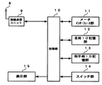
図2は本発明における親機および子機の構成を示すブロック図で、アンテナ8と、アンテナ8に接続され相手局と無線通信を行うための無線通信ユニット9と、親機4または子機7の動作を制御する制御部10と、親機4の場合はT−NCU3と接続するため、およびメータと接続するための、子機7の場合はメータと接続するためのメータインターフェース部11と、自己の無線局の識別符号および使用者識別情報(以下、ユーザIDという)を記憶している自局ID記憶部12と相手の無線局の識別符号およびユーザID等を記憶している相手局ID記憶部13と、相手局登録時および相手局種別表示に使用するスイッチ部14と、相手局登録動作の結果および相手局種別表示等を示す表示部15によって構成される。
FIG. 2 is a block diagram showing the configuration of the parent device and the child device in the present invention. The
図3は本発明における中継機の構成を示すブロック図で、アンテナ8と、アンテナ8に接続され相手局と無線通信を行うための無線通信ユニット9と、中継機6の動作を制御する制御部10と、メータと接続するためのメータインターフェース部11と、自己の無線局の識別符号および使用者識別情報(以下、ユーザIDという)を記憶している自局ID記憶部12と相手の無線局の識別符号およびユーザID等を記憶している相手局ID記憶部13と、相手局登録時および相手局種別表示に使用するスイッチ部14と、相手局登録動作の結果および相手局種別表示等を示す表示部15と、中継機6同士の相手局登録が行われた場合に、相手の中継機6の登録データを記憶する他中継機データ記憶部16によって構成される。
FIG. 3 is a block diagram showing the configuration of the repeater according to the present invention. The control unit controls the operation of the
図4は本発明における親機4、中継機6および子機7の自局ID記憶部12の構成を示すブロック図で、自己の無線局の識別符号を記憶する12桁の識別符号記憶部17と、自己のユーザIDを記憶するユーザID記憶部18によって構成される。
FIG. 4 is a block diagram showing the configuration of the local station ID storage unit 12 of the
図5は本発明における自局ID記憶部12の内のユーザID記憶部18の構成を示すブロック図で、15桁のユーザID部19と、1桁の中継機フラグ部20によって構成される。中継機フラグ部20は、中継機6に登録されている子機7の場合1となり、その他の場合0となる。
FIG. 5 is a block diagram showing the configuration of the user ID storage unit 18 in the local station ID storage unit 12 according to the present invention, which is composed of a 15-digit
図6は本発明における親機4の相手局ID記憶部13の構成を示すブロック図で、相手の無線局の識別符号を記憶する識別符号記憶部21と、相手のユーザIDを記憶するユーザID記憶部22、および相手の無線局が子機7の場合、子機7が登録されている中継機6のユーザIDを、相手の無線局が中継機6の場合、中継機6が記憶している他中継機のユーザIDを記憶する中継機ユーザID記憶部23によって構成される。
FIG. 6 is a block diagram showing the configuration of the counterpart station ID storage unit 13 of the
図7は本発明における中継機6のユーザID記憶部13の構成を示すブロック図で、テーブルNo.24と相手の無線局となる、親機4または子機7の識別符号を記憶する識別符号記憶部25と、対応するユーザIDを記憶するユーザID記憶部26によって構成される。A・B・C・・・は登録可能である子機の台数によって決まり、例えば、16台の子機を登録可能である親機の場合、テーブルNo.24は001から016までとなり、識別符号記憶部25およびユーザID記憶部26はA〜Pまで存在する。
FIG. 7 is a block diagram showing the configuration of the user ID storage unit 13 of the
図8は本発明における中継機の他中継機データ記憶部16の構成を示すブロック図で、テーブルNo.27と相手の無線局となる、他中継機または子機の識別符号を記憶する識別符号記憶部28と、対応するユーザIDを記憶するユーザID記憶部29によって構成される。A・B・C・・・は他中継機に登録されている子機の台数によって決まり、例えば、16台の子機を登録可能である親機の場合、テーブルNo.24は001から016までとなり、識別符号記憶部28およびユーザID記憶部29はA〜Pまで存在する。
FIG. 8 is a block diagram showing the configuration of the repeater
図9は本発明における子機7の相手局ID記憶部13の構成を示すブロック図で、相手の無線局の識別符号を記憶する識別符号記憶部30と、相手のユーザIDを記憶するユーザID記憶部31によって構成される。
FIG. 9 is a block diagram showing the configuration of the counterpart station ID storage unit 13 of the
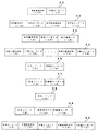
図10は本発明の一実施例である無線テレメータシステムに使用する電文例で、電文32は相手局登録を行う場合に子機から親機または中継機に送信する相手局登録電文で、12桁の自局無線識別符号と16桁の自局ユーザIDで構成される。電文33は前記相手局登録電文32に応じて親機4または中継機から送信する相手局登録応答電文で、12桁の自局無線識別符号と16桁の自局ユーザID、および12桁の相手局無線識別符号と16桁の相手局ユーザIDで構成される。電文34は相手局登録を行う場合に、中継機から親機または他の中継機に対して送信する相手局登録電文で、12桁の自局無線識別符号と16桁の自局ユーザID、および16桁の他中継機IDで構成される。中継機からの電文34に対する、親機および他の中継機の応答電文は、前記電文33が使用される。電文35は親機からの相手局登録応答電文33を受信した場合に、中継機から親機または他の中継機に対して送信する登録データ送信電文で、登録されているN台の子機すべての、12桁の無線識別符号と16桁のユーザIDで構成される。また、相手局登録が中継機同士であった場合、登録データ送信電文35を受信した中継機は、相手の中継機に対して同様に、
登録データ送信電文35を送信する。電文36は中継機が応答しない場合に親機からセンターに送信する応答電文で、4桁のエラーコードと、応答しない中継機の登録データを記憶している中継機の16桁のユーザIDで構成される。電文37は中継機を変更する場合にセンターから親機に送信する中継機変更電文で4桁の変更コマンドと、変更を行う(応答しない)中継機の16桁のユーザIDで構成される。電文38は前記電文37を受信した親機が、応答しない中継機の登録データを記憶している中継機に対して送信する、中継機変更電文で4桁の変更コマンドで構成される。電文39は前記電文38を受信した中継機が、記憶している他中継機に登録されている子機に対して送信する、中継機変更電文で4桁の変更コマンドと、変更後の中継機の、12桁の無線識別符号と16桁のユーザIDで構成される。電文40は子機に対する中継機変更が完了するごとに中継機から親機に送信する中継機変更完了通知電文で、4桁の変更完了コードと、中継機変更を完了した子機7の12桁の無線識別符号と16桁のユーザID、および変更された中継機の12桁の無線識別符号と16桁のユーザIDで構成される。
FIG. 10 is an example of a message used in the radio telemeter system according to an embodiment of the present invention. A message 32 is a partner station registration message transmitted from the slave unit to the master unit or the relay unit when registering the partner station. The local station radio identification code and the 16-digit local station user ID. A telegram 33 is a counterpart station registration response message transmitted from the
A registration data transmission message 35 is transmitted. The telegram 36 is a response telegram transmitted from the master unit to the center when the repeater does not respond, and is composed of a 4-digit error code and a 16-digit user ID of the repeater that stores registration data of the non-responder repeater. Is done. The telegram 37 is a relay station change message transmitted from the center to the parent machine when the relay station is changed, and includes a 4-digit change command and a 16-digit user ID of the relay station that changes (does not respond). The message 38 is a relay device change message that is transmitted from the master device that has received the message 37 to the relay device that stores the registration data of the relay device that does not respond. The message 39 is a relay device change message that is transmitted from the relay device that has received the message 38 to the slave device registered in the other relay device stored therein, and the relay device after the change. Are composed of a 12-digit wireless identification code and a 16-digit user ID. The telegram 40 is a relay station change completion notification message transmitted from the relay station to the master station every time the relay station change for the slave station is completed, and a 4-digit change completion code and the 12 digits of the
図11は本発明の一実施例である無線テレメータシステムの中継機における、相手局登録スイッチ(以下、登録スイッチと略す)が押下された場合の、動作を示すフローチャートである。
図12は本発明の一実施例である無線テレメータシステムの親機における、中継機が不応答であった場合の、動作を示すフローチャートである。
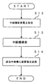
図13は本発明の一実施例である無線テレメータシステムの親機における、中継機変更指示があった場合の、動作を示すフローチャートである。
図14は本発明の一実施例である無線テレメータシステムの中継機における、中継機変更指示があった場合の、動作を示すフローチャートである。
FIG. 11 is a flowchart showing an operation when a partner station registration switch (hereinafter abbreviated as a registration switch) is pressed in a repeater of a wireless telemeter system according to an embodiment of the present invention.
FIG. 12 is a flowchart showing the operation when the repeater does not respond in the base unit of the radio telemeter system according to the embodiment of the present invention.
FIG. 13 is a flowchart showing the operation when there is a repeater change instruction in the base unit of the radio telemeter system according to the embodiment of the present invention.
FIG. 14 is a flowchart showing the operation when a repeater change instruction is issued in the repeater of the wireless telemeter system according to the embodiment of the present invention.
図1において、子機7aを親機4に、子機7b・7cを中継機6aに、子機7dを中継機6bに登録されているものとする。
登録は、例えば子機7aを親機4に登録する場合、工事担当者は子機7aを親機4に登録するために、子機7aのスイッチ部14にある登録スイッチを押下する。この操作により、子機7aから親機4に対して相手局登録電文32が送信される。親機4は子機7aからの相手局登録電文32を受信すると、受信した無線識別符号とユーザIDを相手局ID記憶部13に記憶し、子機7aに対して相手局登録応答電文33を送信する。同様に子機7aは親機4からの相手局登録電文33を受信すると、受信した無線識別符号とユーザIDを相手局ID記憶部13に記憶する。
In FIG. 1, it is assumed that the
For example, when registering the
本発明の一実施例である無線テレメータシステムの中継機のスイッチ部14の登録スイッチが押下された場合の動作を図11のフローチャートに沿って説明する。
中継機6の制御部10は登録スイッチが押下された場合、相手局登録電文34を送信する。これに対する応答電文33の自局ユーザID内の中継機フラグ部を参照し、相手局が親機4であるか他の中継機であるか判断する(ステップS1、以下”ステップ”は省略す
る)。中継機フラグ部が0の場合、相手局が親機であるため通常の相手局登録となり、受信したデータを相手局ID記憶部13の親機識別符号記憶部25と親機ユーザID記憶部26に記憶した後、相手局ID記憶部13に登録されているすべての子機のデータを親機4に対して送信する(S2)。中継機フラグ部が1の場合、相手局が他の中継機なので、受信したデータを他中継機データ記憶部16の中継機識別符号記憶部28と中継機ユーザID記憶部29に記憶した後、相手局ID記憶部13に登録されているすべての子機のデータを相手の中継機に対して送信した後、相手の中継機から送信された、相手の中継機に登録されている子機すべてのデータを受信する(S3)。中継機6の制御部10は前記受信したデータの子機のデータの有無を確認し(S4)、子機のデータが存在する場合、前記受信したデータを他中継機データ記憶部16に記憶する(S5)。子機のデータが存在しない場合、他中継機データ記憶部16の中継機識別符号記憶部28と中継機ユーザID記憶部29のデータを書き換え(S6)、他中継機データ記憶部16に記憶していた他中継機の登録子機のデータを送信する(S7)。
The operation when the registration switch of the switch unit 14 of the repeater of the wireless telemeter system according to the embodiment of the present invention is pressed will be described with reference to the flowchart of FIG.
When the registration switch is pressed, the
登録スイッチが押下された場合、本発明の中継機は上記のように動作するので、相手局が登録子機のデータを持つ中継機の場合、相手中継機の登録子機データを記憶し、相手中継機が故障等で通信できなくなった場合、変更指示により、相手中継機に登録されている子機との通信を行うことができる。また、
相手局が登録子機のデータを持たない中継機の場合、記憶している他中継機の登録子機のデータを、相手中継機に送信するので、再度新しい中継機と故障した中継機に登録されていた子機の、相手局登録作業無しに、故障した中継機を新しい物に変更することができる。
When the registration switch is pressed, the repeater of the present invention operates as described above. Therefore, if the partner station is a repeater having registered slave unit data, the registered slave unit data of the partner repeater is stored and When the relay device becomes unable to communicate due to a failure or the like, it is possible to communicate with the slave device registered in the partner relay device by a change instruction. Also,
If the remote station is a relay station that does not have registered slave unit data, the registered slave unit data of the other relay unit is sent to the partner relay unit, so it is registered again with the new relay unit and the failed relay unit. The failed repeater can be changed to a new one without registering the remote station.
以下、図1の中継機6aが、故障が原因で応答しない場合の、本発明の無線テレメータシステムの動作を図12〜図14のフローチャートに沿って説明する。
親機4は子機7bと通信を行う場合、子機7bが登録されている中継機6aを呼び出す。親機4の制御部10は、中継機6aからの応答を監視し(S8)、中継機6aから応答があった場合、中継機6aとの通信を開始し、中継機6aを経由して子機7bと通信を行う(S9)。中継機6aから応答が無かった場合、相手局ID記憶部13の中継機ユーザID記憶部23を参照し、中継機6aの登録データを記憶している他の中継機が存在するか調べる(S10)。中継機6aの登録データを記憶している他の中継機が存在しない場合、
親機4はセンターに対して、中継機6aが不応答であることを通知し通信を終了する。中継機6aの登録データを記憶している他の中継機bが存在する場合、親機4はセンターに対して、電文36により他の中継機6bのユーザIDを送信する(S11)。
The operation of the wireless telemeter system of the present invention when the repeater 6a of FIG. 1 does not respond due to a failure will be described below with reference to the flowcharts of FIGS.
When the
The
本発明の親機は以上のように動作するので、中継機が不応答の場合、センターでは不応答の中継機のデータを記憶している他の中継機の有無を容易に知ることができる。これによって、中継機が故障していた場合、中継機を交換するまでの間、他の中継機によって故障している中継機に登録されている子機との通信を行うことができ、中継機交換時には、故障している中継機のデータを記憶している他の中継機のユーザIDが判っているので、交換作業が簡単に行える。
センターは親機4より受信した電文36により、中継機6aが不応答で、中継機6aの登録データを記憶している中継機が中継機6bで有ることを知ると、親機4に対して中継機変更電文37を送信する。
中継機変更電文37を受信した親機4の制御部10は(S12)、相手局ID記憶部13を参照し中継機6aの登録データを持つ他の中継機6bを検索する(S13)。親機4の制御部10は、中継機aの登録データを持つ他の中継機6bを見つけると、中継機6bに対して中継機変更電文38を送信する(S14)。
親機4から中継機変更電文38を受信した中継機6bの制御部10は、他中継機データ記憶部16に記憶している中継機6aに登録されている子機7bに中継機変更電文39を送信する(S16)。中継機6bの制御部10は、子機7bの応答を監視し(S17)、応答があった場合、親機4に対して中継機の変更完了を通知する(S18)。中継機6bの制御部10は、親機4に対して中継機の変更完了を通知後、他中継機データ記憶部16に記憶しているデータを参照し、中継機の変更を行っていない子機を検索する(S19)。中継機の変更を行っていない子機7cがあった場合、同様に子機7cに対して中継機を行う。S17で子機7bから応答がない場合S19に進み、子機7bとの通信を終了し、他に中継機の変更を行っていない子機の検索を行う。
Since the master unit of the present invention operates as described above, when the relay station does not respond, the center can easily know the presence or absence of another relay station storing data of the non-responding relay station. As a result, if the relay unit is out of order, communication with the slave unit registered in the relay unit that has failed by another relay unit can be performed until the relay unit is replaced. At the time of replacement, since the user IDs of other relays that store the data of the failed relay are known, the replacement work can be easily performed.
When the center knows from the message 36 received from the
The
The
以上のように本発明の一実施例である無線テレメータシステムは動作するので、中継機が故障等で応答しなくなった場合でも、他の中継機を使用してセンターから子機を呼び出したり、ガス漏れ等の緊急事態が発生した場合に、子機からセンターに通報することができる。
なお、本発明は、一実施例として無線テレメータシステムについて説明したが、端末装置からセンター側装置に異常事態を通報するセキュリティシステム等の無線データ通信システムに適用可能なものである。
As described above, the radio telemeter system according to one embodiment of the present invention operates. Therefore, even when a relay station stops responding due to a failure or the like, a slave station can be called from the center using another relay station, When an emergency such as a leak occurs, the slave unit can notify the center.
Although the present invention has been described with reference to a wireless telemeter system as an embodiment, the present invention can be applied to a wireless data communication system such as a security system that reports an abnormal situation from a terminal device to a center side device.
1 ホストコンピュータ
2 センター側網制御装置
3 T−NCU
4 無線親機
5a〜5g メータ
6a〜6b 無線中継機
7 無線子機
8 アンテナ
9 無線通信ユニット
10 制御部
11 メータインターフェース部
12 自局ID記憶部
13 相手局ID記憶部
14 スイッチ部
15 表示部
16 他中継機データ記憶部
17 識別符号記憶部
18 ユーザID記憶部
19 ユーザID部
20 中継機フラグ部
21 識別符号記憶部
22 ユーザID記憶部
23 中継機ユーザID記憶部
24 テーブルNo.
25 識別符号記憶部
26 ユーザID記憶部
27 テーブルNo.
28 識別符号記憶部
29 ユーザID記憶部
30 識別符号記憶部
31 ユーザID記憶部
32 相手局登録電文
33 相手局登録応答電文
34 相手局登録電文
35 登録データ送信電文
36 応答電文
37 中継機変更電文
38 中継機変更電文
39 中継機変更電文
40 中継機変更完了通知電文
1
4 wireless master device 5a-5g meter 6a-6b
25 ID code storage unit 26 User ID storage unit 27 Table No.
28 Identification
Claims (6)
Priority Applications (1)
| Application Number | Priority Date | Filing Date | Title |
|---|---|---|---|
| JP2005123276A JP4580811B2 (en) | 2005-04-21 | 2005-04-21 | Wireless data communication system |
Applications Claiming Priority (1)
| Application Number | Priority Date | Filing Date | Title |
|---|---|---|---|
| JP2005123276A JP4580811B2 (en) | 2005-04-21 | 2005-04-21 | Wireless data communication system |
Publications (3)
| Publication Number | Publication Date |
|---|---|
| JP2006303943A JP2006303943A (en) | 2006-11-02 |
| JP2006303943A5 JP2006303943A5 (en) | 2008-02-07 |
| JP4580811B2 true JP4580811B2 (en) | 2010-11-17 |
Family
ID=37471698
Family Applications (1)
| Application Number | Title | Priority Date | Filing Date |
|---|---|---|---|
| JP2005123276A Expired - Fee Related JP4580811B2 (en) | 2005-04-21 | 2005-04-21 | Wireless data communication system |
Country Status (1)
| Country | Link |
|---|---|
| JP (1) | JP4580811B2 (en) |
Families Citing this family (6)
| Publication number | Priority date | Publication date | Assignee | Title |
|---|---|---|---|---|
| JP2008276599A (en) * | 2007-05-01 | 2008-11-13 | Dx Antenna Co Ltd | Emergency report system |
| JP2009038660A (en) * | 2007-08-02 | 2009-02-19 | Sharp Corp | Radio telemeter system |
| JP4965527B2 (en) * | 2008-08-07 | 2012-07-04 | ホーチキ株式会社 | Wireless disaster prevention system |
| JP5366579B2 (en) * | 2009-02-09 | 2013-12-11 | キヤノン株式会社 | COMMUNICATION SYSTEM, COMMUNICATION DEVICE, ITS PROCESSING METHOD, AND PROGRAM |
| JP5942734B2 (en) * | 2012-09-20 | 2016-06-29 | 沖電気工業株式会社 | Data collection system, data collection method, adjacent information management server, and program |
| JP6455344B2 (en) * | 2015-06-29 | 2019-01-23 | サクサ株式会社 | Communications system |
Citations (5)
| Publication number | Priority date | Publication date | Assignee | Title |
|---|---|---|---|---|
| JPH08171692A (en) * | 1994-12-16 | 1996-07-02 | Tokyo Gas Co Ltd | Radio communication system |
| JP2000207672A (en) * | 1999-01-11 | 2000-07-28 | Omron Corp | System and method for wireless meter-reading |
| JP2000251187A (en) * | 1999-03-01 | 2000-09-14 | Kokusai Electric Co Ltd | Communication system |
| JP2001136294A (en) * | 1999-11-05 | 2001-05-18 | Toyo Keiki Co Ltd | Automatic meter reading system |
| JP2001217947A (en) * | 2000-02-01 | 2001-08-10 | Toshiba Corp | Wireless terminal |
-
2005
- 2005-04-21 JP JP2005123276A patent/JP4580811B2/en not_active Expired - Fee Related
Patent Citations (5)
| Publication number | Priority date | Publication date | Assignee | Title |
|---|---|---|---|---|
| JPH08171692A (en) * | 1994-12-16 | 1996-07-02 | Tokyo Gas Co Ltd | Radio communication system |
| JP2000207672A (en) * | 1999-01-11 | 2000-07-28 | Omron Corp | System and method for wireless meter-reading |
| JP2000251187A (en) * | 1999-03-01 | 2000-09-14 | Kokusai Electric Co Ltd | Communication system |
| JP2001136294A (en) * | 1999-11-05 | 2001-05-18 | Toyo Keiki Co Ltd | Automatic meter reading system |
| JP2001217947A (en) * | 2000-02-01 | 2001-08-10 | Toshiba Corp | Wireless terminal |
Also Published As
| Publication number | Publication date |
|---|---|
| JP2006303943A (en) | 2006-11-02 |
Similar Documents
| Publication | Publication Date | Title |
|---|---|---|
| JP4580811B2 (en) | Wireless data communication system | |
| US20020118974A1 (en) | System for managing operation status of equipment and apparatus used therein | |
| JP4648205B2 (en) | Wireless telemeter system | |
| JP2006245638A (en) | Alliance method between master unit and slave unit | |
| JP2018120459A (en) | Communication system, communication device, and server | |
| JP5210832B2 (en) | Specific low-power radio telemeter system | |
| JP2005057412A (en) | Wireless data communication system, wireless master unit and wireless slave unit | |
| JP2019054324A (en) | Remote monitoring system | |
| JP2022178581A (en) | Pump device and pump network system | |
| JP5499838B2 (en) | Cordless telephone device and erroneous placement detection method | |
| JP5710378B2 (en) | Wireless telemeter system | |
| JP2013171568A (en) | Radio telemeter system | |
| JP3964671B2 (en) | Mobile radio terminal device | |
| JP2005229426A (en) | Data communication system, radio slave unit, radio master unit and terminal side device used for the same, partner station registration method, installation method of data communication system and starting method of carrier sense operation | |
| KR101500299B1 (en) | Remote repair system and method | |
| JP2020167498A (en) | Public radio communication area extension system, mobile radio terminal, and public radio communication area extension program | |
| JP5168131B2 (en) | Telephone system, telephone control method, and cordless cordless handset | |
| JPH07177572A (en) | Method for automatic message recording for cordless telephone set | |
| JP2007184742A (en) | Wireless telemeter system | |
| JP4881287B2 (en) | Wireless telemeter system | |
| JPH098933A (en) | Automatic metering system | |
| CN111478830A (en) | Remote operation system, communication device, and computer program | |
| JP6454509B2 (en) | Wireless communication system and wireless communication method | |
| JP6063501B2 (en) | Wireless telemeter system | |
| JP5163579B2 (en) | Telephone system, telephone control method, and cordless cordless handset |
Legal Events
| Date | Code | Title | Description |
|---|---|---|---|
| A521 | Written amendment |
Free format text: JAPANESE INTERMEDIATE CODE: A523 Effective date: 20071214 |
|
| A621 | Written request for application examination |
Free format text: JAPANESE INTERMEDIATE CODE: A621 Effective date: 20071214 |
|
| A977 | Report on retrieval |
Free format text: JAPANESE INTERMEDIATE CODE: A971007 Effective date: 20090728 |
|
| A131 | Notification of reasons for refusal |
Free format text: JAPANESE INTERMEDIATE CODE: A131 Effective date: 20090908 |
|
| A521 | Written amendment |
Free format text: JAPANESE INTERMEDIATE CODE: A523 Effective date: 20091019 |
|
| TRDD | Decision of grant or rejection written | ||
| A01 | Written decision to grant a patent or to grant a registration (utility model) |
Free format text: JAPANESE INTERMEDIATE CODE: A01 Effective date: 20100803 |
|
| A01 | Written decision to grant a patent or to grant a registration (utility model) |
Free format text: JAPANESE INTERMEDIATE CODE: A01 |
|
| A61 | First payment of annual fees (during grant procedure) |
Free format text: JAPANESE INTERMEDIATE CODE: A61 Effective date: 20100830 |
|
| FPAY | Renewal fee payment (event date is renewal date of database) |
Free format text: PAYMENT UNTIL: 20130903 Year of fee payment: 3 |
|
| R150 | Certificate of patent or registration of utility model |
Free format text: JAPANESE INTERMEDIATE CODE: R150 |
|
| LAPS | Cancellation because of no payment of annual fees |