JP4580552B2 - Liquid separator for liquid injection compressor - Google Patents
Liquid separator for liquid injection compressor Download PDFInfo
- Publication number
- JP4580552B2 JP4580552B2 JP2000557900A JP2000557900A JP4580552B2 JP 4580552 B2 JP4580552 B2 JP 4580552B2 JP 2000557900 A JP2000557900 A JP 2000557900A JP 2000557900 A JP2000557900 A JP 2000557900A JP 4580552 B2 JP4580552 B2 JP 4580552B2
- Authority
- JP
- Japan
- Prior art keywords
- separation device
- tubular
- oil
- wall
- coarse
- Prior art date
- Legal status (The legal status is an assumption and is not a legal conclusion. Google has not performed a legal analysis and makes no representation as to the accuracy of the status listed.)
- Expired - Fee Related
Links
- 239000007788 liquid Substances 0.000 title description 10
- 238000002347 injection Methods 0.000 title description 3
- 239000007924 injection Substances 0.000 title description 3
- 238000000926 separation method Methods 0.000 claims description 56
- 239000000463 material Substances 0.000 claims description 8
- 239000002657 fibrous material Substances 0.000 claims description 7
- 238000001816 cooling Methods 0.000 claims description 5
- 239000003507 refrigerant Substances 0.000 description 8
- 239000000835 fiber Substances 0.000 description 7
- 230000035515 penetration Effects 0.000 description 5
- 230000035699 permeability Effects 0.000 description 4
- 229920003235 aromatic polyamide Polymers 0.000 description 3
- LVGUZGTVOIAKKC-UHFFFAOYSA-N 1,1,1,2-tetrafluoroethane Chemical compound FCC(F)(F)F LVGUZGTVOIAKKC-UHFFFAOYSA-N 0.000 description 2
- 239000012530 fluid Substances 0.000 description 2
- 239000010964 304L stainless steel Substances 0.000 description 1
- OKTJSMMVPCPJKN-UHFFFAOYSA-N Carbon Chemical compound [C] OKTJSMMVPCPJKN-UHFFFAOYSA-N 0.000 description 1
- 229920000049 Carbon (fiber) Polymers 0.000 description 1
- 229920000271 Kevlar® Polymers 0.000 description 1
- 229920006231 aramid fiber Polymers 0.000 description 1
- 229910052799 carbon Inorganic materials 0.000 description 1
- 230000008859 change Effects 0.000 description 1
- 239000000470 constituent Substances 0.000 description 1
- 239000004744 fabric Substances 0.000 description 1
- 230000006872 improvement Effects 0.000 description 1
- 239000004761 kevlar Substances 0.000 description 1
- 239000000203 mixture Substances 0.000 description 1
- 230000000149 penetrating effect Effects 0.000 description 1
- 230000002093 peripheral effect Effects 0.000 description 1
- 239000007921 spray Substances 0.000 description 1
- 238000003466 welding Methods 0.000 description 1
Images

Classifications
-
- B—PERFORMING OPERATIONS; TRANSPORTING
- B01—PHYSICAL OR CHEMICAL PROCESSES OR APPARATUS IN GENERAL
- B01D—SEPARATION
- B01D17/00—Separation of liquids, not provided for elsewhere, e.g. by thermal diffusion
- B01D17/02—Separation of non-miscible liquids
-
- F—MECHANICAL ENGINEERING; LIGHTING; HEATING; WEAPONS; BLASTING
- F04—POSITIVE - DISPLACEMENT MACHINES FOR LIQUIDS; PUMPS FOR LIQUIDS OR ELASTIC FLUIDS
- F04C—ROTARY-PISTON, OR OSCILLATING-PISTON, POSITIVE-DISPLACEMENT MACHINES FOR LIQUIDS; ROTARY-PISTON, OR OSCILLATING-PISTON, POSITIVE-DISPLACEMENT PUMPS
- F04C29/00—Component parts, details or accessories of pumps or pumping installations, not provided for in groups F04C18/00 - F04C28/00
- F04C29/02—Lubrication; Lubricant separation
- F04C29/026—Lubricant separation
-
- B—PERFORMING OPERATIONS; TRANSPORTING
- B01—PHYSICAL OR CHEMICAL PROCESSES OR APPARATUS IN GENERAL
- B01D—SEPARATION
- B01D29/00—Filters with filtering elements stationary during filtration, e.g. pressure or suction filters, not covered by groups B01D24/00 - B01D27/00; Filtering elements therefor
- B01D29/50—Filters with filtering elements stationary during filtration, e.g. pressure or suction filters, not covered by groups B01D24/00 - B01D27/00; Filtering elements therefor with multiple filtering elements, characterised by their mutual disposition
-
- F—MECHANICAL ENGINEERING; LIGHTING; HEATING; WEAPONS; BLASTING
- F25—REFRIGERATION OR COOLING; COMBINED HEATING AND REFRIGERATION SYSTEMS; HEAT PUMP SYSTEMS; MANUFACTURE OR STORAGE OF ICE; LIQUEFACTION SOLIDIFICATION OF GASES
- F25B—REFRIGERATION MACHINES, PLANTS OR SYSTEMS; COMBINED HEATING AND REFRIGERATION SYSTEMS; HEAT PUMP SYSTEMS
- F25B43/00—Arrangements for separating or purifying gases or liquids; Arrangements for vaporising the residuum of liquid refrigerant, e.g. by heat
- F25B43/02—Arrangements for separating or purifying gases or liquids; Arrangements for vaporising the residuum of liquid refrigerant, e.g. by heat for separating lubricants from the refrigerant
Landscapes
- Engineering & Computer Science (AREA)
- Chemical & Material Sciences (AREA)
- Chemical Kinetics & Catalysis (AREA)
- Mechanical Engineering (AREA)
- General Engineering & Computer Science (AREA)
- Physics & Mathematics (AREA)
- Thermal Sciences (AREA)
- Applications Or Details Of Rotary Compressors (AREA)
- Filtering Of Dispersed Particles In Gases (AREA)
- Compressor (AREA)
Description
【0001】
(技術分野)
本発明は、液体注入コンプレッサ用の液体分離装置、特に油分離装置が配置された油注入状らせん形スクリュー冷却コンプレッサに関するものである。
【0002】
(背景技術)
コンプレッサの出口通路に直接備え付けられた現行の液体分離装置は、相対的に効果的ではなく、しばしばキャリーオーバーが3.5〜4.5パーセントの間になり、最高の場合、キャリーオーバーは2〜3パーセントの間である。実際に前記値は不適切なほど大きく、その値を減らすことは有利である。
【0003】
(発明の開示)
本発明による油分離装置を備えた油注入らせん形スクリュー冷却コンプレッサにおいては、
油分離装置が、二つの垂直な端壁に配置され、そして内側の管状粗分離装置と外側の管状細分離装置とを備え、
内側の管状粗分離装置及び外側の管状細分離装置がそれらの間に中空間を形成するように互いに間隔をあけて配置され、
一方の端壁が、内側の管状粗分離装置の内部管状領域をコンプレッサにおける圧縮ガスの出口通路に連通する開口部を備え、
内側の管状粗分離装置と外側の管状細分離装置がガス及び油透過材で構成され、
内側の管状粗分離装置がネット層を備え、
ネット層を通るガス流量が0.2メートル/秒より多く、0.5メートル/秒より少ないようにされ、
ネット層が、多数の開口部を備えかつ内側の管状粗分離装置の内側境界を構成する管状内壁に設けられ、
内側の管状粗分離装置が、総壁領域の少なくとも50パーセントに相当する面積の多数の開口部をもつ管状外壁を備え、
外側の管状細分離装置が、油を吸収しない有孔繊維材料を備え、
有孔繊維材料が、管状有孔内壁と管状有孔外壁と間に設けられていること
を特徴としている。
【0009】
(発明の開示)
上記より明らかなように、液体分離装置は、内部の粗分離装置(coarse separator)と、粗分離装置の放射状外側に配置された細分離装置(fine separator)とを具備した二つの分離段を有しており、それによって、液滴を含むガスが、放射状外向きに中間自由空間を介して通り、そこでガス流が細分離装置に流れる少し前に止まることできる。この構造の油分離装置によって、油のキャリーオーバー値が0〜0.6パーセントほどに小さくなると考えられる。
【0010】
特に液体分離装置の適切な実施例は、これらキャリーオーバー値を小さくするため、付随の独立請求項に記載された特徴を有する。
【0011】
(発明を実施するための最良の形態)
添付図面を参照して、本発明を詳しく説明する。
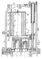
図1において、らせん状冷却コンプレッサの高圧部分は、1で示されており、その高圧端壁が2で示されている。端壁2はその上に、ハウジング3が装着されており、ハウジングは、本発明により構成された油分離装置4を具備している。コンプレッサ1は、油分離装置4へ通じる入口開口部6と中心で向かい合った、出口通路またはダクト5有している。油分離装置4は、垂直な第一端壁7を有し、コンプレッサ1に近い側の第一端壁の端部に、入口開口部6を具備している。
【0012】
前記入口開口部の周縁部には、第一貫通スリーブ12(第一の管状壁)の一端部が、例えば溶接によって固定されている。該スリーブ12は、本質的に水平である。第一スリーブ12の他の端部は、ディスク形部材13によって閉じられている。
【0013】
前記第一スリーブ12の外側には、第二貫通スリーブ14(第二の管状壁)が同軸に配置されている。コンプレッサに面したスリーブ14の端部は、端壁7の円溝7aに挿入されている。粗分離装置9は、前記貫通スリーブ12、14の間に形成された空間に配置され、前記スリーブが、粗分離装置を適所に保持する管状壁を形成する。
【0014】
また図示の液体分離装置4は、細分離装置10を具備しており、その分離装置は、互いに間隔をあけ且つ互いに同軸の貫通スリーブ、すなわち第三スリーブ16(第三の管状壁)と第四スリーブ17(第四の管状壁)との間で、第三スリーブ16の外側に配置されている。前記スリーブ16及び17を具備した細分離装置10は、粗分離装置9の外部で間隔11をあけて配置されている。この間隔11により形成されるキャビティは、粗分離装置9と細分離装置10との間に設けられている。前記スリーブ16及び17の第一端部は、第一端壁7における溝7aに受けられている。
【0015】
また液体分離装置4は、ディスクプレート13と並行且つ同軸の第二端壁8を具備している。端壁8は溝8aを具備しており、そこに第二、第三及び第四スリーブ14、16及び17が挿入され、ボルト及びナット継手15によって、適所に保持される。
【0016】
前記ボルトは、第二端壁8の開口部を介して、ディスクプレート13の中心部に挿入される。四つの貫通スリーブ12、14、16及び17の全ての管状壁が、スリーブ領域の50パーセントを越える開口部領域を占めている。
【0017】
粗分離装置9は、スパンワイヤーネット例えば“Becoil Demister Mech:304 L stainless steel type H”であり得、前記ネットは合わせて2.5〜3.5 cmの厚さになる多数の層に応用される。ネットは、堅くまたは密に巻かれ、計算されたガスの流量が、0.2メートル/秒よりも多く、0.5メートル/秒よりも少ない。このフィルターは、油分離プロセスを構成し、油の流れ(80〜90%)の主部分をシステムから分離させる。
【0018】
前記ネット層は、第一及び第二スリーブ12及び14の管状壁により、目標密集度で適所に保持され、これらスリーブの開口部領域は、スリーブ(管状壁)表面の領域の50パーセントを越える。スリーブの孔の直径は、8〜10mmである。
【0019】
第三スリーブ16及び第四スリーブ17により、適所に保持される細分離装置10は、防油性及び反油性繊維から成る有孔繊維から構成されている。繊維組織は、第三貫通スリーブ16の周囲に緩く巻かれて、その厚さは6〜8mmである。粗分離装置9で分離された油を排出し、また粗分離装置9から出る流体の流れに残る良好に分けられた油に有効な分離装置を形成することができるように、繊維組織の層に関し、重量あたりの組織層の構成領域によって決められる、有孔性を確定する必要がある。
【0020】
本発明によると、繊維組織は、構成領域あたりの重量が、厚さ1ミリメートルの繊維の一平方メートルのあたり130〜170グラムである。 繊維材料と接触させる油が基準的な温度の場合、前記材料はポリアラミド繊維材料または、何らかの対応する材料から成る。油の温度がより高い場合、従来はカーボン繊維またはアラミド繊維材料、好ましくはパラアラミド材料(KEVLAR、パラアラミド繊維に関する商標名、所有者DU PONT、米国)を材料として使用する。
【0021】
冷却コンプレッサ1が作動中のとき、冷媒、例えば大滴或いは小滴の油を含んだR134a(テトラフルオロエタン、CF3CFH2)は、噴霧する大きさになって、コンプレッサの出口通路5から出て、約6メートル/秒またはそれよりも高い流量で、油分離装置4の出口開口部を介して入る。入口開口部6と逆側にある第一スリーブ12の端部におけるディスクプレート13が、スリーブと平行な連続流を妨げるので、冷媒の流れは方向を変え、第一スリーブ12における開口部または貫通孔を介して、放射状に外部へと続く。冷媒は粗分離装置9を介し、且つ第二スリーブ14を通って、放射状に流れる。
【0022】
殆どの油滴は、粗分離装置のネットとスリーブ(管状壁)の表面で留められ、そこから流れ落ちて、粗分離装置9を出て、外管またはスリーブ14の最下方開口部または貫通孔を通過する。油滴冷媒は細分離装置10を介して、放射状に外部へ流れ続け、残りの油の殆どが流体の流れから分離される。
【0023】
従ってスリーブ14は、粗分離装置によって抽出され且つ、粗分離装置の下方部分から流れ落ちる油の収集面としてとして、機能する。粗分離装置から排出する油は、スリーブ14の外部でキャビティ11の下方部分に収集される。キャビティ11は、約1.5から2.5cmほど放射状に延長している。粗分離装置から流れ落ちる油は、60°から90°に相当するキャビティ11の底部セグメントを満たし、外部の細分離装置10を介して排出する。細分離装置の内側制限部が、キャビティまたは空間11の外側制限部を形成する。
【0024】
粗分離装置9によって分離され、且つ細分離装置10の最下方部で収集される油は、繊維布地の下方セグメント状部分を介して排出され、この前記分離装置10の油排出セグメント部分が、前記分離装置10の円筒状外形の60°から90°に相当し、外形の残り270°〜300°が、細分離機の油分離領域を形成する。それを超えて残るきれいに分けられた油が、冷媒から抽出される。油分離装置が、有効に動作させ且つ、ガスの貫流及び油の貫流に関して平衡にするため、油のレベルが細分離装置10の領域の多くても25パーセントだけを占めるようにしなければならない。すなわちセグメントが90°を超えないようにすること、及びまた細分離装置10を介するガス流量を、0.1メートル/秒以上とすることである。
【0025】
本発明による液体含有ガスの分離の改善を、説明することが難しいのは、粗分離装置9及び細分離装置10を介する液滴の通過を調べるのが困難だからである。図2に示されるような、油のキャリーオーバーを示す曲線、すなわちガスに添加する油は、冷媒R134aを使用する冷却コンプレッサにおいて、計量を行うことによって得られる。図2は、冷媒の揮発温度を関数として、ガス状冷媒に添加する油の重量パーセントで、濃度を示している。垂直ワイヤーネットプレート形の通常配置した油分離装置を具備した、同じコンプレッサを駆動させる時、3〜10パーセントの油キャリーオーバーを得る。このパーセンテージの変化は、揮発温度によるものである。
【0026】
本発明は、その一例として図示され且つ記載された実施例に限定されるものではなく、これは請求項で定義された本発明の範囲内で、幾つかの方法に変形することができる。例えば、数字の値は異なる動作状態により変えることができ、スリーブ12、14及び16、17は全てまたは幾つかは、対応する透過性の剛性ネット構造体と取り代えることができる。前記剛性ネット構造体の大きな透過性が、従来囲まれる粗分離材料及び、細分離材料の個々の低い透過性によって、補償される場合でも、その様な剛性ネット構造体の透過性は、孔のあいたスリーブの透過性よりも高い。分離スリーブは、円形のほかに、正方形、五角形などのような断面形状でもよいことは、明らかである。またスリーブは、テーパー状でもよい。
【図面の簡単な説明】
【図1】らせん状スクリューコンプレッサの高圧端壁上に装着された本発明による油分離装置の一例として選択された実施例の長手方向断面図と、コンプレッサの一部の長手方向断面図。
【図2】冷媒の揮発温度を関数として、図1に示された油分離装置から繰り越された油のパーセンテージを示したグラフ
【符号の説明】
1 コンプレッサ
4 油分離装置
6 入口開口部
9 粗分離装置
10 細分離装置
11 空間(キャビティ)
12 第一貫通スリーブ(第一管状壁)
14 第二貫通スリーブ(第二管状壁)
16 第三貫通スリーブ(第三管状壁)
17 第四貫通スリーブ(第四管状壁) [0001]
(Technical field)
The present invention relates to a liquid separation device for a liquid injection compressor, and more particularly to an oil injection helical screw cooling compressor in which an oil separation device is arranged .
[0002]
(Background technology)
Current liquid separators installed directly in the compressor outlet passage are relatively ineffective, often carryover is between 3.5 and 4.5 percent, and at best, carryover is between 2 and 3 percent It is. In practice, this value is inappropriately large and it is advantageous to reduce that value.
[0003]
(Disclosure of the Invention)
In the oil-injected helical screw cooled compressor equipped with the oil separator according to the present invention,
An oil separator is disposed on the two vertical end walls and comprises an inner tubular coarse separator and an outer tubular fine separator;
The inner tubular coarse separation device and the outer tubular fine separation device are spaced apart from each other so as to form an intermediate space therebetween;
One end wall includes an opening that communicates the inner tubular region of the inner tubular coarse separation device to the compressed gas outlet passage in the compressor;
The inner tubular coarse separation device and the outer tubular fine separation device are composed of gas and oil permeable material,
The inner tubular rough separation device has a net layer,
The gas flow rate through the net layer is greater than 0.2 meters / second and less than 0.5 meters / second;
A net layer is provided on the tubular inner wall with a large number of openings and constituting the inner boundary of the inner tubular coarse separator;
The inner tubular coarse separation device comprises a tubular outer wall having a number of openings with an area corresponding to at least 50 percent of the total wall area;
The outer tubular subdivision device comprises a perforated fiber material that does not absorb oil,
The porous fiber material is provided between a tubular perforated inner wall and a tubular perforated outer wall .
[0009]
(Disclosure of the Invention)
As is clear from the above, the liquid separator has two separation stages with a coarse separator inside and a fine separator arranged radially outside the coarse separator. Thereby allowing the gas containing the droplets to pass radially outward through the intermediate free space, whereupon the gas flow can stop shortly before flowing into the fine separation device. With this structure of the oil separator, it is considered that the oil carry-over value is reduced to about 0 to 0.6%.
[0010]
Particularly suitable embodiments of the liquid separation device have the features set out in the accompanying independent claims in order to reduce these carryover values.
[0011]
(Best Mode for Carrying Out the Invention)
The present invention will be described in detail with reference to the accompanying drawings.
In FIG. 1, the high pressure portion of the helically cooled compressor is indicated by 1 and its high pressure end wall is indicated by 2. The
[0012]
One end of the first through sleeve 12 (first tubular wall) is fixed to the peripheral edge of the inlet opening by, for example, welding. The sleeve 12 is essentially horizontal. The other end of the first sleeve 12 is closed by a disk-shaped member 13.
[0013]
A second through sleeve 14 (second tubular wall) is coaxially disposed outside the first sleeve 12. End of the sleeve 14 facing the compressor is inserted in a circular groove 7a of the
[0014]
The illustrated liquid separation device 4 includes a
[0015]
The liquid separation device 4 includes a second end wall 8 that is parallel to and coaxial with the disk plate 13. The end wall 8 has a groove 8a into which the second, third and
[0016]
The bolt is inserted into the center portion of the disc plate 13 through the opening of the second end wall 8. All tubular walls of the four
[0017]
The
[0018]
The net layer is held in place by the tubular walls of the first and second sleeves 12 and 14 , with the opening area of these sleeves exceeding 50 percent of the area of the sleeve (tubular wall) surface. The diameter of the hole in the sleeve is 8-10 mm.
[0019]
The
[0020]
According to the present invention, the fiber structure has a weight per constituent area of 130-170 grams per square meter of 1 millimeter thick fiber. When the oil in contact with the fiber material is at a standard temperature, the material consists of a polyaramid fiber material or some corresponding material. For higher oil temperatures, conventionally carbon or aramid fiber material, preferably para-aramid material (KEVLAR, trade name for para-aramid fiber, owner DU PONT, USA) is used as material.
[0021]
When the
[0022]
Most of the oil droplets are clamped at the surface of the coarse separator net and sleeve (tubular wall) , flow down from there, exit the
[0023]
The sleeve 14 thus functions as a collecting surface for the oil extracted by the coarse separator and flowing down from the lower part of the coarse separator. The oil discharged from the coarse separation device is collected in the lower part of the
[0024]
The oil separated by the
[0025]
The improvement of the separation of the liquid-containing gas according to the present invention is difficult to explain because it is difficult to examine the passage of droplets through the
[0026]
The invention is not limited to the embodiment shown and described by way of example, which can be varied in several ways within the scope of the invention as defined in the claims. For example, the numerical values can be changed by different operating conditions, and all or some of the
[Brief description of the drawings]
FIG. 1 shows a longitudinal section of an embodiment selected as an example of an oil separator according to the invention mounted on the high-pressure end wall of a helical screw compressor and a longitudinal section of a part of the compressor.
FIG. 2 is a graph showing the percentage of oil carried over from the oil separator shown in FIG. 1 as a function of the volatilization temperature of the refrigerant.
[Explanation of symbols]
1 Compressor
4 Oil separator
6 Entrance opening
9 Coarse separator
10 Fine separation device
11 Space (cavity)
12 First penetration sleeve (first tubular wall)
14 Second penetration sleeve (second tubular wall)
16 Third penetration sleeve (third tubular wall)
17 Fourth penetration sleeve (fourth tubular wall)
Claims (1)
前記油分離装置(4)が、二つの垂直な端壁(7,8)に配置され、そして内側の管状粗分離装置(9)と外側の管状細分離装置(10)とを備え、
前記内側の管状粗分離装置(9)及び外側の管状細分離装置(10)がそれらの間に中空間(11)を形成するように互いに間隔をあけて配置され、
一方の端壁(7)が、内側の管状粗分離装置(9)の内部管状領域をコンプレッサ(1)のにおける圧縮ガスの出口通路(5)に連通する開口部(6)を備え、
前記内側の管状粗分離装置(9)と外側の管状細分離装置(10)がガス及び油透過材で構成され、
前記内側の管状粗分離装置(9)がネット層を備え、
前記ネット層を通るガス流量が0.2メートル/秒より多く、0.5メートル/秒より少ないようにされ、
前記ネット層が、多数の開口部を備えかつ前記内側の管状粗分離装置(9)の内側境界を構成する管状内壁に設けられ、
前記内側の管状粗分離装置(9)が、総壁領域の少なくとも50パーセントに相当する面積の多数の開口部をもつ管状外壁を備え、
前記外側の管状細分離装置(10)が、油を吸収しない有孔繊維材料を備え、
前記有孔繊維材料が、管状有孔内壁と管状有孔外壁と間に設けられていること
を特徴とする油分離装置を備えた油注入らせん形スクリュー冷却コンプレッサ。An oil-injected helical screw cooling compressor with an oil separator,
The oil separation device (4) is arranged on two vertical end walls (7, 8) and comprises an inner tubular coarse separation device (9) and an outer tubular fine separation device (10);
The inner tubular coarse separation device (9) and the outer tubular fine separation device (10) are spaced apart from each other so as to form an intermediate space (11) therebetween;
One end wall (7) comprises an opening (6) communicating the inner tubular region of the inner tubular coarse separation device (9) with the compressed gas outlet passage (5) of the compressor (1),
The inner tubular coarse separation device (9) and the outer tubular fine separation device (10) are composed of gas and oil permeable material,
The inner tubular coarse separation device (9) comprises a net layer;
The gas flow rate through the net layer is greater than 0.2 meters / second and less than 0.5 meters / second;
The net layer is provided on a tubular inner wall having a large number of openings and constituting the inner boundary of the inner tubular coarse separation device (9);
The inner tubular coarse separation device (9) comprises a tubular outer wall having a number of openings with an area corresponding to at least 50 percent of the total wall area;
The outer tubular fine separation device (10) comprises a perforated fiber material that does not absorb oil;
An oil-injected helical screw cooling compressor equipped with an oil separator, wherein the perforated fiber material is provided between a tubular perforated inner wall and a tubular perforated outer wall.
Applications Claiming Priority (3)
| Application Number | Priority Date | Filing Date | Title |
|---|---|---|---|
| SE9802432-6 | 1998-07-07 | ||
| SE9802432A SE512435C2 (en) | 1998-07-07 | 1998-07-07 | Liquid separator for a liquid-injected compressor, in particular an oil separator for an oil-injected screw rotor compressor |
| PCT/SE1999/001028 WO2000001461A1 (en) | 1998-07-07 | 1999-06-11 | Liquid separator for a liquid injected compressor |
Publications (2)
| Publication Number | Publication Date |
|---|---|
| JP2003520919A JP2003520919A (en) | 2003-07-08 |
| JP4580552B2 true JP4580552B2 (en) | 2010-11-17 |
Family
ID=20411990
Family Applications (1)
| Application Number | Title | Priority Date | Filing Date |
|---|---|---|---|
| JP2000557900A Expired - Fee Related JP4580552B2 (en) | 1998-07-07 | 1999-06-11 | Liquid separator for liquid injection compressor |
Country Status (7)
| Country | Link |
|---|---|
| EP (1) | EP1123150B1 (en) |
| JP (1) | JP4580552B2 (en) |
| KR (1) | KR100638686B1 (en) |
| DE (1) | DE69931945T2 (en) |
| DK (1) | DK1123150T3 (en) |
| SE (1) | SE512435C2 (en) |
| WO (1) | WO2000001461A1 (en) |
Families Citing this family (2)
| Publication number | Priority date | Publication date | Assignee | Title |
|---|---|---|---|---|
| JP7292904B2 (en) * | 2019-03-06 | 2023-06-19 | 住友重機械工業株式会社 | Oil separators, filter elements, and compressors for cryogenic refrigerators |
| CN112833093B (en) | 2019-11-25 | 2025-07-15 | 斯凯孚公司 | Bearing arrangement |
Family Cites Families (10)
| Publication number | Priority date | Publication date | Assignee | Title |
|---|---|---|---|---|
| JPS5676018U (en) * | 1979-11-13 | 1981-06-20 | ||
| GB2075597B (en) * | 1980-05-02 | 1983-10-26 | Hydrovane Compressor | Rotary air compressors |
| GB2120122B (en) * | 1982-05-14 | 1986-04-30 | Marshall D A G | Air filter element |
| US4478054A (en) * | 1983-07-12 | 1984-10-23 | Dunham-Bush, Inc. | Helical screw rotary compressor for air conditioning system having improved oil management |
| US4662190A (en) * | 1985-12-10 | 1987-05-05 | Tischer James C | Integral slide valve-oil separator apparatus in a screw compressor |
| JP3452334B2 (en) * | 1994-06-02 | 2003-09-29 | 株式会社荏原製作所 | Oil separator |
| JPH10137505A (en) * | 1996-11-07 | 1998-05-26 | Kiichi Watanabe | Oil purifying device for air compressor system |
| JPH1172363A (en) * | 1997-08-29 | 1999-03-16 | Osaka Gas Co Ltd | Vortex flow meter |
| JPH11128633A (en) * | 1997-10-31 | 1999-05-18 | Osaka Gas Co Ltd | Filter and its production |
| JP2007296431A (en) * | 2006-04-28 | 2007-11-15 | Hitachi Metals Ltd | Metal porous sintered member filter |
-
1998
- 1998-07-07 SE SE9802432A patent/SE512435C2/en not_active IP Right Cessation
-
1999
- 1999-06-11 DK DK99933332T patent/DK1123150T3/en active
- 1999-06-11 JP JP2000557900A patent/JP4580552B2/en not_active Expired - Fee Related
- 1999-06-11 KR KR1020007014891A patent/KR100638686B1/en not_active Expired - Fee Related
- 1999-06-11 DE DE69931945T patent/DE69931945T2/en not_active Expired - Lifetime
- 1999-06-11 EP EP99933332A patent/EP1123150B1/en not_active Expired - Lifetime
- 1999-06-11 WO PCT/SE1999/001028 patent/WO2000001461A1/en not_active Ceased
Also Published As
| Publication number | Publication date |
|---|---|
| DK1123150T3 (en) | 2006-10-16 |
| SE9802432L (en) | 2000-01-08 |
| WO2000001461A1 (en) | 2000-01-13 |
| EP1123150A1 (en) | 2001-08-16 |
| SE9802432D0 (en) | 1998-07-07 |
| KR20010071633A (en) | 2001-07-28 |
| JP2003520919A (en) | 2003-07-08 |
| EP1123150B1 (en) | 2006-06-14 |
| DE69931945D1 (en) | 2006-07-27 |
| DE69931945T2 (en) | 2007-02-01 |
| KR100638686B1 (en) | 2006-10-27 |
| SE512435C2 (en) | 2000-03-20 |
| WO2000001461A8 (en) | 2000-02-24 |
Similar Documents
| Publication | Publication Date | Title |
|---|---|---|
| US6997974B2 (en) | High strength and ultra-efficient oil coalescer | |
| EP0583770B1 (en) | Two-stage helical oil separator | |
| US8557007B2 (en) | Air/oil separator and inlet baffle arrangement | |
| US10710013B2 (en) | Compact axial flow separator | |
| WO1993023146A1 (en) | Filter system for compressed air | |
| CA2062579C (en) | In-line filter device for compressed air having mist filter and air collector | |
| US20080034784A1 (en) | Combined oil separator and muffler for refrigerant compressor | |
| US20030014951A1 (en) | Horizontal separator tank for oil-flooded air compressor | |
| JPH01194919A (en) | Back flow depth filter assembly and production thereof | |
| US20030021714A1 (en) | Screw compressor | |
| JP4580552B2 (en) | Liquid separator for liquid injection compressor | |
| JPH10300286A (en) | Sludge trapping device, method of manufacturing the same, and refrigeration and air-conditioning equipment provided with sludge trapping device | |
| WO2000036305A1 (en) | Centrifugal compressor oil sump demister apparatus | |
| EP3705815B1 (en) | Oil separator, filter element, and compressor for cryocooler | |
| JP5601764B2 (en) | Gas-liquid separator and air compressor and air conditioner equipped with the same | |
| JP2001501292A (en) | Separation device for separating liquid from gas | |
| EP0085206B1 (en) | Separator for compressed air | |
| JP2006029684A (en) | Oil separator and cryogenic device | |
| JP3452334B2 (en) | Oil separator | |
| US3578168A (en) | Refrigerating apparatus having oil-separating means | |
| JP2002213360A (en) | Oil separator for oil cooled compressor | |
| JPH0320707Y2 (en) | ||
| JPS58210355A (en) | Fuel strainer | |
| TWI905357B (en) | Oil separator for compressor unit and compressor unit for cryocooler | |
| JPH06165B2 (en) | Separator for compressor |
Legal Events
| Date | Code | Title | Description |
|---|---|---|---|
| A621 | Written request for application examination |
Free format text: JAPANESE INTERMEDIATE CODE: A621 Effective date: 20060526 |
|
| A131 | Notification of reasons for refusal |
Free format text: JAPANESE INTERMEDIATE CODE: A131 Effective date: 20090225 |
|
| A521 | Request for written amendment filed |
Free format text: JAPANESE INTERMEDIATE CODE: A523 Effective date: 20090525 |
|
| RD13 | Notification of appointment of power of sub attorney |
Free format text: JAPANESE INTERMEDIATE CODE: A7433 Effective date: 20090527 |
|
| A521 | Request for written amendment filed |
Free format text: JAPANESE INTERMEDIATE CODE: A821 Effective date: 20090527 |
|
| A02 | Decision of refusal |
Free format text: JAPANESE INTERMEDIATE CODE: A02 Effective date: 20090721 |
|
| A521 | Request for written amendment filed |
Free format text: JAPANESE INTERMEDIATE CODE: A523 Effective date: 20091124 |
|
| A911 | Transfer to examiner for re-examination before appeal (zenchi) |
Free format text: JAPANESE INTERMEDIATE CODE: A911 Effective date: 20100217 |
|
| A131 | Notification of reasons for refusal |
Free format text: JAPANESE INTERMEDIATE CODE: A131 Effective date: 20100414 |
|
| A521 | Request for written amendment filed |
Free format text: JAPANESE INTERMEDIATE CODE: A523 Effective date: 20100714 |
|
| TRDD | Decision of grant or rejection written | ||
| A01 | Written decision to grant a patent or to grant a registration (utility model) |
Free format text: JAPANESE INTERMEDIATE CODE: A01 Effective date: 20100804 |
|
| A01 | Written decision to grant a patent or to grant a registration (utility model) |
Free format text: JAPANESE INTERMEDIATE CODE: A01 |
|
| A61 | First payment of annual fees (during grant procedure) |
Free format text: JAPANESE INTERMEDIATE CODE: A61 Effective date: 20100830 |
|
| FPAY | Renewal fee payment (event date is renewal date of database) |
Free format text: PAYMENT UNTIL: 20130903 Year of fee payment: 3 |
|
| R150 | Certificate of patent or registration of utility model |
Free format text: JAPANESE INTERMEDIATE CODE: R150 |
|
| LAPS | Cancellation because of no payment of annual fees |