JP4580098B2 - Pachinko machine jigs, pachinko machine carts, systems using these, and work methods - Google Patents
Pachinko machine jigs, pachinko machine carts, systems using these, and work methods Download PDFInfo
- Publication number
- JP4580098B2 JP4580098B2 JP2000388502A JP2000388502A JP4580098B2 JP 4580098 B2 JP4580098 B2 JP 4580098B2 JP 2000388502 A JP2000388502 A JP 2000388502A JP 2000388502 A JP2000388502 A JP 2000388502A JP 4580098 B2 JP4580098 B2 JP 4580098B2
- Authority
- JP
- Japan
- Prior art keywords
- pachinko gaming
- gaming machine
- inner frame
- jig
- pachinko
- Prior art date
- Legal status (The legal status is an assumption and is not a legal conclusion. Google has not performed a legal analysis and makes no representation as to the accuracy of the status listed.)
- Expired - Fee Related
Links
Images

Landscapes
- Pinball Game Machines (AREA)
Description
【0001】
【発明の属する技術分野】
本発明は、パチンコ遊技機用治具およびパチンコ遊技機用台車に関し、更にはこの治具を用いたパチンコ遊技機の作業方法および作業システムに関する。
【0002】
【従来の技術】
パチンコ遊技機は、木、合成樹脂、金属、ガラスなど、異種の材料が複合的に用いられているので、使用後、そのまま廃棄すると、環境に与える負担は大きい。そこで、解体することで、分別廃棄や部品の一部再使用などが行なわれている。部品をパチンコ遊技機を構成する枠体から取り外し、更にこれを金属、プラスチック、木、ガラスなどの材料別に分別することで、破砕あるいは溶融といった処理を容易にし、廃棄または再生使用するために行なわれるされる(例えば特開平9−122630号参照)。
【0003】
こうした解体において、パチンコ遊技機からモータや制御盤、あるいはガラスなどの取り外しは、パチンコ遊技機を、作業台などの上に置き、通常は人手によって行なわれていた。
【0004】
【発明が解決しようとする課題】
しかしながら、最近のパチンコ遊技機では、遊技盤裏側の構成が複雑化しており、パチンコ遊技機から部品を取り外そうとすると、パチンコ遊技機を裏返したり、立てたり、寝かせたりなど、煩瑣な手間を要するという問題があった。作業台の上に、回収したパチンコ遊技機を置いて作業したのでは、極めて効率が悪いという問題があった。
【0005】
なお、こうした問題は、実際には、人手によりパチンコ遊技機を組み立てる場合でも生じていた。パチンコ遊技機の構成が複雑になるに連れて、自動機を用いることなく、パチンコ遊技機を組み立てようとすると、様々な部品を取り付けるために、パチンコ遊技機を裏返したり、寝かせたり、立てたりといった煩瑣な作業が必要になっていた。
【0006】
本発明は、上記の課題を解決し、使用済みのパチンコ遊技機の解体または組立作業を用意することを目的として、以下の構成を取った。
【0007】
【課題を解決するための手段およびその作用・効果】
本発明のパチンコ遊技機用治具は、
パチンコ遊技機の組立または解体に用いる治具であって、
パチンコ遊技機が固定される内フレームと、
該内フレームを回転可能に軸支する外フレームと、
前記内フレームを、前記外フレームに対して定まる2以上の回転位置で固定可能な固定機構と
を備えたことを要旨とする。
【0008】
かかる治具は、パチンコ遊技機の組立はまたは解体に用いられるが、そのうちフレームにはパチンコ遊技機が固定される。このとき、うちフレームは、これを回転自在に軸支する外フレームに対して、2以上の回転位置で固定可能である。従って、パチンコ遊技機を内フレームごと回転することができ、いちいちパチンコ遊技機を作業台の上で裏返したり、寝かせたりする必要がない。この結果、パチンコ遊技機の組立や解体の作業が極めて容易になる。
【0009】
かかるパチンコ遊技機用治具において、内フレームを、パチンコ遊技機を固定したまま、少なくとも180度、外フレームに対して回転可能とすることができる。少なくとも180度回転できれば、パチンコ遊技機の裏表に対して、同方向から作業可能となり、組立または解体作業が容易となる。
【0010】
かかるパチンコ遊技機用治具において、
前記固定機構は、
前記パチンコ遊技機の枠体を、該枠体の一の側部における側部両端から挟持して固定する第1の固定手段と、
該側部とは反対側の一側部において、前記枠体を、前記パチンコ遊技機の前後方向から挟持して固定する第2の固定手段と
を備えたものとすることができる。
この場合、第1の固定手段により、枠体をその一の側部における側部両側から挟持し、第2の固定手段により、枠体をその前後方向から挟持して固定するので、枠体の固定位置の位置決めを、少なくとも2方向に対して、精度よく行なうことができる。こうした効果は、特にこのパチンコ遊技機用治具を、ある位置で作業しその後別の位置に移動してまた作業を行なうといった使い方では、治具に固定されたパチンコ遊技機の位置が変動して、作業に障害を生じると言うことがない。また、パチンコ遊技機の枠体を、一の側部ではその側部両端から挟持し、反対側の側部では前後方向から挟持しているので、内フレームごとパチンコ遊技機を回転した際に、パチンコ遊技機が脱落するということがない。
【0011】
ここで、第1,第2の固定手段が固定する枠体は、パチンコ遊技機の外枠、内枠あるいは前枠のうちのいずれかとすることができる。これらのどの枠体を固定する場合でも、その枠体に取り付けられた部品に対する作業が容易となる。
【0012】
また、こうしたパチンコ遊技機用治具において、内フレームを、その一辺に、前記パチンコ遊技機の枠体の対応する一辺が係合される係合部を備えると共に、該一辺とは反対側の一辺に、前記パチンコ遊技機の枠体の対応する一辺を載置する載置部材と、該載置部材との間に、該パチンコ遊技機の該一辺を挟み込んで固定するクランプ機構とを備えた構成とすることができる。かかる構成を採用すれば、クランプ機構を操作するだけで、パチンコ遊技機を内フレームに容易に固定することができる。また、クランプ機構によりパチンコ遊技機の枠体の一辺を載置部材上に挟み込んで固定するので、枠体、ひいてはパチンコ遊技機が浮き上がることがない。
【0013】
上記軸では、内フレームは、外フレームに対して回転する。そこで、内フレームに、内フレームを回転させるための把手を備えることも、作業性を向上する上で好適である。更に、この把手を操作することにより、内フレームが外フレームに対して回転しないように固定し、また当該固定を解除するものとすることができる。この場合、把手の操作だけで、固定と固定の解除ができるので、作業が容易になると言う利点が得られる。こうした固定とその解除を行なう手段は、内フレームの固定位置に対応して少なくとも2箇所に設けることができる。このとき、固定とその解除を行なう手段には、把手に連接された係合部と、把手を係合部ごと、内フレームの回転方向と交差する方向に移動可能に保持する移動機構と、係合部と係合することにより、係合部を固定する固定部とを設け、把手を、上記の交差方向に移動することにより、係合部が固定部から離脱して、内フレームが回転可能な状態となり、内フレームが回転して、把手の係合部が、回転位置に設けられた固定とその解除を行なう手段の固定部に係合することにより、内フレームを固定するものとしても良い。この場合、回転した内フレームを固定したり、その固定を解除したりする際の把手の移動方向は、内フレームの回転方向に交差する方向となっているから、作業者が把手にうっかり触ったりした場合でも、内フレームが回転してしまったりすることがない。
【0014】
また、このパチンコ遊技機用治具に、電動機と、該電動機の回転を伝達する伝達機構と、該伝達機構を介して伝達される動力により前記内フレームを所望の位置まで回転する回転機構とを備えるものとしても良い。こうすれば、電動機を用いて内フレームおよびこれに固定したパチンコ遊技機を回転することができるので、作業がよい簡易なものとなる。
【0015】
こうした治具においては、回転した内フレームを、所定の位置で固定する固定具を備えることも望ましい。作業を行なうときに、内フレームが所定の位置で固定されていれば、作業が容易になるからである。こうした固定位置は、予め定めた1カ所または複数箇所としても良いし、任意の位置で固定できるものとしても良い。
【0016】
なお、こうした治具は、種々の材料で構成することがきるが、パチンコ遊技機のように20キログラム前後の重量を有するものを取り扱う場合には、内フレームおよび外フレームをアルミニウム製とすることが、治具全体の軽量化と剛性とを両立させる点から望ましい。もとより、ステンレス、ジュラルミン、その他の軽合金などを用いることも差し支えない。耐久性をさほど重視しない場合には、木製や合成樹脂などを用いることも可能である。
【0017】
上記治具を用いて、パチンコ遊技機用台車を構成することができる。即ち、かかるパチンコ遊技機用台車は、
前記したパチンコ遊技機用治具の少なくとも一の構成を備えたパチンコ遊技機用治具と、
該パチンコ遊技機用治具を載置する車輪付きの載置台と
を備えたことを要旨としている。
【0018】
かかる台車は、車輪を付きの載置台を有するので、前記のパチンコ遊技機用治具を搭載したまま(従って、パチンコ遊技機を固定したまま)、容易に、移動することができる。この結果、例えば解体作業や組立作業が、特定の作業を行なう特定の場所の組合わせとして構成されている場合など、パチンコ遊技機を固定したまま、これらの場所間を自在に移動することができ、解体や組立の作業を簡易に行なうことができる。
【0019】
更に、車輪を回転駆動する電動機を備えるものとすれば、台車を自走もしくは小さな力で移動させることができ、好適である。
【0020】
また、上述したパチンコ遊技機用治具を用いて、新規で有用なパチンコ遊技機の解体や組立を行なう作業システムを構成することができる。即ち、かかるパチンコ遊技機のシステムは、
前記パチンコ遊技機を立設したまま組立または解体作業を行なう作業用ラインと、
上述したパチンコ遊技機用治具のいずれかと、
前記作業用ラインから前記パチンコ遊技機を前記パチンコ遊技機用治具に移し替える移行手段と、
該パチンコ遊技機を前記内フレームに固定した前記パチンコ遊技機用治具を、前記内フレームごと前記パチンコ遊技機を回転可能な状態で搬送する治具搬送手段と
を備えたことを要旨としている。
【0021】
かかる作業システムによれば、作業用ラインのなかで、上述したパチンコ遊技機用治具を用いることで、作業用ラインにおけるパチンコ遊技機の回転を容易に実現し、パチンコ遊技機の裏表などからの部品の取付や解体を容易にする。
【0022】
また、本発明の他の作業システムとして、
パチンコ遊技機の組立または解体の作業を行なうシステムであって、
パチンコ遊技機を、固定する内フレームと、
該内フレームを回転自在に保持する外フレームと、
該内フレームを前記外フレームに対して、異なる2以上の回転位置で固定する固定手段と
を備えたパチンコ遊技機用治具と、
該パチンコ遊技機用治具を組立または解体作業箇所まで移動する搬送手段と
をそなえた構成を考えることもできる。
【0023】
かかる構成でも、作業において、この治具の内フレームにパチンコ遊技機を固定することで、パチンコ遊技機の回転を容易に実現し、パチンコ遊技機の裏表などからの部品の取付や解体を容易にすることができる。
【0024】
上述した固定用治具を利用したパチンコ遊技機の組立や解体の作業方法の発明を構成することができる。即ち、かかる作業方法は、
パチンコ遊技機にに対して部品を組立または解体の作業を行なう方法であって、
パチンコ遊技機を、固定用治具に設けられた外フレームに対して回転自在に軸支された内フレームに固定し、
該内フレームを前記外フレームに対して第1の回転位置で固定し、
該第1の位置に固定された前記パチンコ遊技機に対して、部品を取付または解体する第1の作業を行ない、
該第1の作業の完了後に、前記内フレームを前記外フレームに対して回転し、前記第1の位置とは異なる第2の位置に固定し、
該第2の位置に固定された前記パチンコ遊技機に対して、他の部品を取付または解体する第2の作業を行なうこと
を要旨としている。
【0025】
この作業方法によれば、固定用治具の内フレームに固定されたパチンコ遊技機を、内フレームを外フレームに対して回転することで、第1の回転位置に固定し、ここでパチンコ遊技機に対して部品を取付または解体する第1の作業を行なう。この作業の完了後、内フレームを外フレームに対して回転し、第1の位置とは異なる第2の位置に固定し、ここで他の部品を取付または解体する第2の解体作業を行なう。従って、外フレームに対して回転自在な内フレームを有する固定用治具を用いて、少なくとも第1および第2の位置でパチンコ遊技機を固定し、パチンコ遊技機に対して、それぞれの位置で容易に部品を取付または解体することができる。
【0026】
ここで、第2の位置での前記第2の作業は、第1の位置に対して、パチンコ遊技機の表裏の異なる側から前記部品を取付または解体する作業とすることができる。回転によって、パチンコ遊技機の表裏を、簡単に作業者の前に位置させることができるので、作業の効率を高めることができる。
【0027】
【発明の実施の形態】
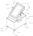
本発明の実施の形態を、実施例に基づき説明する。図1は、実施例のパチンコ遊技機用治具310の概略構成を示す斜視図である。このパチンコ遊技機用治具310は、パチンコ遊技機PPの解体と組立のラインで用いられる。そこで、まずパチンコ遊技機PPの解体と組立ラインについて、図2ないし図6を用いて説明する。
【0028】
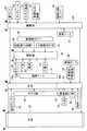
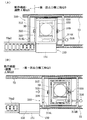
図2は、パチンコ遊技機PPの解体と組立ラインを備えたパチンコ遊技機製造システム10の概要を示す説明図である。図2に示すように、パチンコ遊技機製造システム10は、工場FC1内に、解体ラインQL、部品検査・調整ラインTAL,TBLおよび製造ラインPLという3つのラインを設けることによって構成される。そこで、以下、▲1▼製造ラインPLおよびその作業内容、▲2▼解体ラインQL、▲3▼部品検査・調整ラインTAL,TBL、▲4▼解体ラインの作業内容の順に、これらの構成および作業内容について説明する。
【0029】
▲1▼製造ラインPLおよびその作業内容:
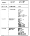
まず、パチンコ遊技機の製造に必要な各種部品の組み付け等を行なう製造ラインPLについて、図2を参照しつつ簡単に説明する。製造ラインPLは、ローラコンベヤ90にそって、順次部品が取り付けられて、パチンコ遊技機PPが製造されるよう構成されており、その製造工程は、図2に示したように、遊技板機構板組立工程P1、内枠組立工程P2、動作確認・調整工程P3、外枠組立工程P4、包装工程P5から構成されている。また、ローラコンベヤ90の周囲には、製造用の部品を収納した多数の収納部が配置されている。これらを図3に一覧表示した。収納ラックPB1は外枠組立工程P4に、収納具PB3は内枠組立工程P2に、収納箱PB4および収納箱PB5は遊技板・機構板組立工程P1に、それぞれ設けられており、各収納ラック、収納箱などには、外枠22など、その組立工程で必要とされる部品が収納されている。なお、これらの収納ラック、収納箱に収納されている部品は新品であり、後述するように、一度出荷された製品から解体・回収された部品(再生部品)が、同様の収納ラックQB1や収納具QB2,QB3、収納箱QB4,QB5に収納されて、各工程P1ないしP4に置かれている。これらの再生品については、後述する。
【0030】
遊技板・機構板組立工程P1では、図4に示すように、機構板50に、発射レール51,球タンク52,タンクレール53,入出力基板54,制御回路ボックス55,賞球払出し装置56等を取り付ける作業を行なう。更に、遊技板40に、裏から球誘導ユニット46,入賞検出手段47,図柄表示装置48を、また表には、誘導レール41,障害釘42,風車43,入賞口44,表示ランプ45などを取り付ける作業も行なう。
【0031】
内枠組立工程P2では、遊技板40および機構板50が取り付けられた内枠30に、更に表示ランプ31,ガラス扉32,装飾板33,上皿34,下皿35,発射ハンドル36,打球発射回路基板37,発射モータ38などを取り付ける作業を行なう。なお、上記の順序は取り付け順序とは必ずしも一致するものではない。また、明示的には記載しなかったが、各部品が取り付けられると、これらの部品間の配線も、同時に行なわれる。従って、内枠組立工程P2が完了した時点で、内枠30に組み付けられた各部品は、電源さえ供給すれば、動作可能となっている。
【0032】
そこで、次に、動作確認・調整工程P3に移行し、ここで内枠30に組み付けられた各種部品の動作確認や調整作業を行なう。予めラインに用意した電源を接続し、玉の発射やその発射個数などの確認・調整などを行なうのである。ここで、動作が確認され、規定の範囲に調整されたものだけが、次の外枠組立工程P4に移される。動作確認などができなったものは、不具合品として製造ラインから外される。
【0033】
動作確認・調整工程P3で良品と判断されたものは、次の外枠組立工程P4に移行される。外枠組立工程P4では、遊技板40および機構板50が取り付けられた状態の内枠30が、外枠22の枠内に嵌め込まれる。以上の工程により、パチンコ遊技機の製造が完了する。この外枠組立工程P4の下流には、更に、包装工程P5が設けられている。包装工程は、部品等の組み付け、外枠への取付が完了したパチンコ遊技機PPに、袋状のポリエチレン製のシート(厚み約0.04mm)を被せて包装する工程である。ここでは、外枠組立工程P4と包装工程P5の詳細は、省略するが、両工程を経て、製造ラインPLの終端に至ったパチンコ遊技機は、そのまま出荷可能な状態となっている。
【0034】
▲2▼解体ラインQL:
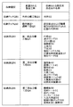
以上、製造ラインPLの各工程P1〜P5について説明した。次に、パチンコ遊技機製造システム10を構成するもう一つのラインである解体ラインQLおよび部品検査・調整ラインTAL,TBLについて、図2,図5ないし図7を参照しつつ説明する。図5は、収納ラックQB1,QB2および収納具QB3,QB4,QB5に収納される部品の一覧を示す説明図である。図6は、解体ラインQLにおいて使用済みのパチンコ遊技機80から外枠22が取り外される様子を示す説明図であり、図7は、解体ラインQLに設けられたねかせ装置150を示す説明図である。
【0035】
図2に示したように、解体ラインQLは、部品検査・調整ラインTAL,TBLを挟んで、製造ラインPLの向かい側に設けられている。解体ラインQLは、使用済みのパチンコ遊技機80(以下、旧機80という)を、ねかせ装置150まだ連続的に運搬するローラコンベヤ70と、ねかせ装置150の下流側に敷設されたレール72を備える。このローラコンベヤ70およびレール72は、製造ラインPLのローラコンベヤ90と略平行に敷設されている。
【0036】
ローラコンベヤ70上で行なわれる流れ作業は、外枠分離工程Q1、動作確認・調整工程Q2、第一部品分離工程Q3、第二部品分離工程Q4という四つの工程に区分される。外枠分離工程Q1,動作確認・調整工程Q2,第一部品分離工程Q3,第二部品分離工程Q4の作業領域は、図2に示したように、それぞれ外枠組立工程P4,動作確認・調整工程P3,内枠組立工程P2,遊技板・機構板組立工程P1が行なわれる作業領域と対向した位置に配置されている。
【0037】
図2において、向かって左から右への白抜きの矢印で示すように、ローラコンベヤ70上に旧機80がセットされた後、各工程Q1,Q2,Q3,Q4がこの順に行なわれることにより、旧機80から外枠22等の旧機80を構成する各種部品が順次に分離され、この結果、旧機80が解体される。本実施例では、パチンコ遊技機においては各種部品の分離順序が各種部品の組み立て順序とほぼ逆順となることを考慮し、解体ラインQLにおける工程の進行方向を製造ラインPLにおける工程の進行方向とは逆の向きとしている。
【0038】
図2では、各工程Q1,Q2,Q3,Q4における作業者の位置を二重丸印を用いて示している。この各工程Q1,Q2,Q3,Q4における作業者の位置の近傍には、それぞれ、収納ラックQB1,収納ラックQB2,収納具QB3,収納具QB4,収納具QB5が設けられている。この収納ラックQB1,QB2および収納具QB3,QB4,QB5に、各工程Q1〜Q4において旧機80から分離された部品(以下、既使用部品Mという)等が収納される。各収納ラックQB1,QB2および収納具QB3,QB4,QB5に収納される既使用部品Mの一覧を図5に示した。なお、この図5の内容については、後述する各工程Q1〜Q4における具体的な作業内容と併せて説明する。
【0039】
収納ラックQB1,QB2および収納具QB3,QB4,QB5の脚部にはキャスタが設けられている。従って、作業者は、収納ラックQB1,QB2および収納具QB3,QB4,QB5を手で押すことにより、収納ラックQB1,QB2および収納具QB3,QB4,QB5を部品検査・調整ラインTBLや製造ラインPLまで簡単に移動させることができる。勿論、リフト機等の他の運搬装置により収納ラックQB1,QB2および収納具QB3,QB4,QB5を移動することとしても差し支えない。また、収納ラックQB1,QB2および収納具QB3,QB4,QB5の回収や移動に関する運搬装置の動作を制御し、作業を自動化することも可能である。
【0040】
▲3▼部品検査・調整ラインTAL,TBL:
図2に示したように、解体ラインQLの外枠分離工程Q1と製造ラインPLの外枠組立工程P4との間の領域には、外枠分離工程Q1において分離された既使用部品M(具体的には、外枠22)を検査ないし調整する部品検査・調整ラインTALが設けられている。部品検査・調整ラインTALは、外枠22が吊り下げられる検査ボード76を備える。この検査ボード76上において、既使用部品Mとしての外枠22の外観を検査および調整する作業(外観検査・調整工程TA1)が行なわれる。
【0041】
また、解体ラインQLの第一部品分離工程Q3および第二部品分離工程Q4と製造ラインPLの内枠組立工程P2および遊技板・機構板組立工程P1との間の領域には、各部品分離工程Q3,Q4において分離された既使用部品Mを検査ないし調整する部品検査・調整ラインTBLが設けられている。部品検査・調整ラインTBLは、既使用部品Mを置いて検査作業や調整作業を行なうための作業台78を備える。この作業台78で行なわれる作業は、外観検査・調整工程TB1、機能検査・調整工程TB2という二つの工程に区分されている。図2に白抜きの矢印で示すように、まず、外観検査・調整工程TB1において既使用部品Mの外観についての検査ないし調整がなされ、次に、機能検査・調整工程TB2において既使用部品Mの機能についての検査ないし調整がなされる。
【0042】
▲4▼解体ラインQLにおける作業内容:
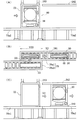
解体ラインQLの各工程Q1,Q2,Q3,Q4で行なわれる作業の内容について、以下、具体的に説明する。まず、外枠分離工程Q1では、ローラコンベヤ70上の旧機80から外枠22を取り外す。旧機80から外枠22が取り外される様子を図6に示す。図6(A)、図6(B)は、それぞれ外枠分離工程Q1に配設されたローラコンベヤ70の立面、上面を示している。
【0043】
図6(B)に示すように、外枠分離工程Q1におけるローラコンベヤ70は、コンベヤ70a1,コンベヤ70a2という二本のコンベヤによって構成されている。コンベヤ70a2は、コンベヤ70a1の終端よりも上流側の領域を始端として、コンベヤ70a1と平行に且つ隣接して配設されている。このため、図6(B)に示す範囲YZ2においては、コンベヤ70a1およびコンベヤ70a2の双方が重複して配設された状態となっている。
【0044】
図6(A)に示すように、コンベヤ70a1の上方には、コンベヤ70a1上の旧機80の外枠22上端面を下方向に押圧する押圧装置243が配設されている。一方、コンベヤ70a2の上方には、内枠30の上端を摺動可能に挟持する誘導レール242が配置されている。この誘導レール242は、範囲YZ2を除くコンベヤ70a2の上方に敷設される。
【0045】
図6(A)に示すように、コンベヤ70a1の上流側から搬送されてきた旧機80はコンベヤ70a1の終端部(図6に示す範囲YZ2領域)において停止する。この後、押圧装置243が作動することにより、旧機80は、押圧装置243とコンベヤ70a1との間で挟持固定される。外枠分離工程Q1領域に配置された作業者は、図6(B)に矢印X1で示すように、固定された状態の旧機80から遊技板40および機構板50が取り付けられた状態の内枠30を取り外し、この内枠30を、台座241を介してコンベヤ70a2上の所定の位置に置く。
遊技板40および機構板50が取り付けられた状態の内枠30は、図6(C)に矢印X2で示すように、誘導レール242に支持され、起立した状態でコンベヤ70a2上を搬送されていき、動作確認・調整工程Q2領域に進入する。
【0046】
一方、コンベヤ70a1上に残った外枠22は、押圧装置243による押圧が解除された後に、既使用部品Mとして収納ラックQB1に収納される(図5を参照)。
【0047】
内枠30が動作確認・調整工程Q2に進入すると、まず、コンベヤ70a2の駆動が一時停止される。この後、遊技板40および機構板50と一体の内枠30を電源に繋ぎ、内枠30に取り付けられている各種部品の動作が出荷品として適当な状態か否かを確認する。具体的には、発射ハンドル36の操作時における球跳び状態、表示ランプ31,45の点灯状態、入賞時における入賞口44や賞球払出し装置56の動作状態等を作業者による試行によって確認する。
【0048】
各種部品の動作が出荷品として不適当な状態である場合には、手直しによる調整を行なう。例えば、発射される遊技球の弾発力が弱いと確認された場合には、発射ハンドル36の遊びの範囲等を調整する。賞球を払い出す際に払出し装置56に球詰まりが生じる場合には、払出し装置56を清掃する等により、球詰まりが生じないように調整する。
【0049】
こうした確認作業ないし調整作業によって再使用品として適当な状態であることが確認された遊技板40および機構板50と一体の内枠30は、ローラコンベヤ70上から除去され、パチンコ遊技機の一部として再び使用することができる部品(以下、再使用可能部品MAという)として収納ラックQB2に収納される(図5を参照)。再使用可能部品MAが収納された収納ラックQB2は、製造ラインPLの外枠組立工程P4領域に送られる。(図2を参照)。
【0050】
一方、内枠30が再使用品として適当な状態でないか否かが確認された場合には、コンベヤ70a2を再び駆動し、起立した状態の内枠30を、第一部品分離工程Q3の最上流域に設けられた寝かせ装置150に送り込む。解体ラインQLは、記述したように、この寝かせ装置150のところで、ローラコンベヤ70とレール72とに分かれている。図7に示すように、解体ラインQLのうち、寝かせ装置150から下流側、即ち第一部品分離工程Q3領域および第二部品分離工程Q4領域では、ローラコンベヤ70に替えて、手動で回転するローラ付きの二本のレール72が設けられている。この二本のレール72上にはパチンコ遊技機用治具310が載せられている。動作確認・調整工程Q2までは、立った状態で、ローラコンベヤ70上を搬送されてきた旧機80は、寝かせ装置150により90度寝かされた状態にされ、パチンコ遊技機用治具310に移し替えられる。
その後の工程については、旧機80は、パチンコ遊技機用治具310に搭載された状態で、2本のレール72上を搬送されることになるのである。なお、この実施例では、以下の分離工程において、遊技板40や機構板50は、内枠30に固定されているものとして説明するが、遊技板40や機構板50については、先の動作確認・調整工程Q2において内枠30から分離解体し、これらの板およびその板に搭載された部品が付いていない状態の内枠30を、部品分離工程Q3のパチンコ遊技機用治具310に装着するものとしても良い。
【0051】
寝かせ装置150は、図7(A)に示すように、動作確認・調整工程Q2のローラコンベヤ70の終端に位置し、ここまで立った状態で搬送された旧機80を、90度回転して寝かせ、パチンコ遊技機用治具であるパチンコ遊技機用治具310に取り付ける装置である。寝かせ装置150は、その詳細な図示を省略するが、寝かせ装置150の動作を制御する制御機構が収納された本体151と、本体151の上方に位置し旧機80を挟み込む昇降アーム部155と、図示しない回転駆動機構とからなり、ローラコンベヤ70により搬送された旧機80を本体151と昇降アーム部155との間に挟持し、回転機構により、図7(A)の状態に寝かせる。
【0052】
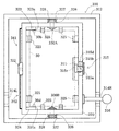
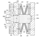
このように旧機80を回転して寝かした状態にすると、旧機80の真下には、パチンコ遊技機用治具310が位置した状態となる。次に、パチンコ遊技機用治具310の構成について図1および図8,図9を参照しつつ説明する。図8はパチンコ遊技機用治具310の上面を示す説明図、図9はパチンコ遊技機用治具310における軸体330A周辺の縦断面を示す説明図である。
【0053】
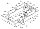
図1に示したように、パチンコ遊技機用治具310は、二本のレール72幅と略同幅の外フレーム312と、この外フレーム312よりも幅狭の内フレーム320を備える。外フレーム312および内フレーム320は共に金属製である。
内フレーム320の枠内は、遊技板40および機構板50と一体の内枠30を収納可能な寸法で形成されている。本実施例では、外側枠312や内側枠320は、アルミニウムの押出材により形成されている。もとより、ステンレスやジュラルミンなども使用可能である。
【0054】
図2および図8に示すように、内フレーム320は外フレーム312の枠内に配置されており、内フレーム320の短辺側側面の中央部と外フレーム312の短辺側の側面の中央部とは軸体330A,330Bで接続されている。また、外フレーム312の長辺側の側面には、二つの切欠部314L,314Rが互いに対向する位置に形成されており、切欠部314Rと向かい合う位置の内フレーム320の長辺側側面には、外フレーム312の長辺側側面の外側に突出する長さのレバー316が装着されている。
【0055】
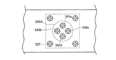
内フレーム320と外フレーム312との軸体330Aによる接続構造について図9を参照しつつ説明する。なお、図9では、内フレーム320と外フレーム312とを上方において接続する軸体330A周りの断面を示しているが、内フレーム320と外フレーム312とを下方において接続する軸体330B周りも図9と同様の構造を採る。図9に示すように、外フレーム312の短辺側側面の中央部内側には凹所313が形成されており、この凹所313には軸体330Aの一端が嵌め込まれている。凹所313に嵌め込まれた軸体330Aの一端は、外フレーム312の外側から四本のねじ345a〜dで締め付けられて(図10を参照)、外フレーム312に螺着される。
【0056】
なお、外フレーム312と内フレーム320との間の空間には、左右のプレート326,327との係合によって保持された皿ばね328が装着されている。
この皿ばね328の装着により、外フレーム312と内フレーム320との間の隙間を一定に保つことが可能となる。
【0057】
図9に示すように、内フレーム320の短辺側側面の中央部には、軸体330Aの軸径よりもやや大径の貫通孔321が形成されており、軸体330Aの他端は、この貫通孔321を貫通している。貫通後の軸体330Aの周囲にはベアリング331が装着されており、このベアリング331の外周部は中空略円筒形のプレート332で覆われながらプレート332と嵌合している。このように、ベアリング331と嵌合されたプレート332は、内フレーム320の内側から四本のねじ(図9では、上下二本のねじを二点鎖線で示す)で締め付けられて、内フレーム320に螺着される。これにより、内フレーム320は、プレート332を介してベアリング331の外周部に装着された状態となる。
【0058】
一方、軸体330Aの他端には、ベアリング331の内周部を覆う大きさの座金333が挿入され、この座金333は、軸体330Aの他端に形成されたねじ部へのナット334の螺着に伴ってベアリング331の内周部に圧設される。これにより、外フレーム312に螺着された軸体330Aは、ナット334,座金333を介してベアリング331の内周部に装着された状態となる。よって、内フレーム320は、ベアリング331の外周部の作用により、外フレーム312に螺着された軸体330Aの周りを回転することができる。
【0059】
従って、図1において、外フレーム312を固定した状態で、切欠部314Rに置かれたレバー316を矢印D方向に動かすと、この方向に内フレーム320が回転する。内フレーム320が矢印D方向に180度回転すると、レバー316は反対側の切欠部314Lに位置する。
【0060】
図1および図8に示したように、内フレーム320の短辺側の各内側面および長辺側の各内側面には、それぞれ二個の受け台325が所定の間隔をおいて装着されている。図8に二点鎖線で示すように各受け台325の上に遊技板40および機構板50と一体の内枠30が載ることにより、内枠30は横向きに内フレーム320内に収納される。
【0061】
内フレーム320の短辺側内側面の隅部には、係合ピン323aを有する機構部323および係合ピン324aを有する機構部324が、互いに対向する位置関係で設けられている。係合ピン323aは、内枠30が内フレーム320内に収納された状態において、内枠30の上端面に設けられた穿設孔30bと対向する位置に設けられる。また、係合ピン324aは、内枠30が内フレーム320内に収納された状態において、内枠30の下端面に設けられた穿設孔30dと対向する位置に設けられる。また、内フレーム320の一方の長辺側上端面の中央付近には、上記機構部323,324とクランク機構341,342で接続されたT字型のハンドル322が突設されている。
【0062】
図1および図8は、ハンドル322が引かれていない状態を示しており、この状態において係合ピン323a,324aは、機構部323,324の表面よりも僅かに突出している。この状態からハンドル322を図1に示す矢印A方向に引くと、クランク機構341,342を介した機構部323,324の作用により、係合ピン323a,324aが矢印B方向に大きく突出する。これにより、係合ピン323a,係合ピン324aは、それぞれ、内枠30の上端面の穿設孔30b,内枠30の下端面の穿設孔30gに係合する。
【0063】
このクランク機構341,342の構造について、図11を用いて更に詳しく説明する。図11は、ハンドル322を操作した場合に、係合ピン323a,324bが、内フレーム320方向に移動する様子を示す説明図である。この図11は、図1におけるAA矢視に相当する図である。図11(A)に示すように、ハンドル322のその下部には、左右、即ち内フレーム320の一側部に沿って、機構部323,324まで延出されたクランク機構341,342が設けられている。このクランク機構341,342は、ハンドル322を挟んで対称形をしており、それぞれ、支持ガイド350に支持されて図示BX方向に移動可能な上方昇降杆351および下方昇降杆352を備える。この上方昇降杆351および下方昇降杆352は、ハンドル322に、連携軸343および上方連携軸346,下方連携軸347により接合されている。
【0064】
図11(A)に示した状態から、ハンドル322を内フレーム320側に押し込むと、連携軸343は、上方連携軸346,下方連携軸347との結合点CPを、ハンドル322の移動方向に押し込む。上方連携軸346と下方連携軸347の他端が結合された上方昇降杆351および下方昇降杆352は、支持ガイド350により、矢印BX方向にのみ動作可能にガイドされているから、上方連携軸346,下方連携軸347の移動は、結果的に、上方昇降杆351および下方昇降杆352を、両者の中心方向(ハンドル322の存在する方向)に引き込むことになる。ハンドル322の移動後のこの状態を示すのが、図11(B)である。図示するように、ハンドル322が押し込まれたことで、上方昇降杆351,下方昇降杆352は、両者の中心方向に移動し、両杆351,352の外側端部に固定された可動板361,362を、内側(内枠30の存在する側)に移動する。この結果、この可動板361,362に、内方向に向けて設けられ、機構部323,324を構成する係合ピン323a,324aもまた、内側に移動する。こうした、係合ピン323a,324aが、内フレーム320の内部にセットされた内枠30の穿設孔30b,30gに係合する。
【0065】
この係合により、内フレーム320内に収納された内枠30の左側半分が内枠30内に固定された状態となる。なお、外枠22に内枠30を開閉係脱可能に取り付けるために設けられた蝶板に穿設された軸受孔を穿設孔30bとする構成としても良い。また、穿設孔30b,30dの一方のみを係合ピンとの係合に用い、他方の側は、内枠30の肩部を収納する枠係止ホルダなどに収納して固定するものとしても良い。枠係止ホルダの形状については、後述する(図15参照)。
【0066】
なお、上記の係合を解除する場合には、ハンドル322を引き上げればよい。
この場合には、上述した動作と逆向きの動作により、ハンドル322の引き上げに伴って、上方昇降杆351,下方昇降杆352は互いに遠ざかる方向に移動する。この結果、可動板361,362に固定された係合ピン323a,324aが、内枠30に対して後退し、その穿設孔30b,30gから離脱し、内フレーム320に対する内枠30の係合を解除する。
【0067】
内フレーム320の他方の長辺側(機構部323,324と離間している方の長辺側)中央付近には、コの字型に切り欠かれた切欠部が形成されており、この切欠部における上端面には、操作部315a,操作部315aとアーム315bを介して接続されたゴム製の押圧体315c,アーム315bを回転可能に軸支する軸支部315dからなるロック機構315が設けられている。このロック機構315が設けられた位置の近傍の内フレーム320の内側面には、二つの受け台325の間に、この受け台325と同じ高さで受け台325よりも長寸の受け台311が装着されている。
【0068】
図1および図8は、操作部315aがニュートラルボジションにある状態を示しており、この状態において押圧体315cは、内フレーム320の上端面よりも上方に位置している。この状態から操作部315aを図1に示す矢印C方向に倒すと、軸支部315dに軸支されたアーム315bが矢印C方向に回転する。
アーム315bが約90度回転して、押圧体315cが内フレーム320の上端面よりも下方の位置に移動すると、軸支部315d内のストッパーの作用により、アーム315bの回転移動は、正方向および逆方向の双方について禁止される。このアーム315bの回転移動の禁止により、内フレーム320内に収納された内枠30は、受け台311と押圧体315cとの間で挟持され、右側半分が内枠30内に固定された状態となる。
【0069】
したがって、上記構成のパチンコ遊技機用治具310では、遊技板40および機構板50と一体の内枠30を内フレーム320内に収納して、ハンドル322を図1に示す矢印A方向に引き、ロック機構315の操作部315aを図1の矢印C方向に約90度回転することにより、内フレーム320内に内枠30が固定される。以上の操作により、旧機80の内枠30は、内フレーム320に完全に固定されてる。この固定は、内枠30の穿設孔30b,30gの存在する側では、内枠30に対してその高さ方向(図1矢印B方向)から係合ピン323a,324aが進入することにより行なわれ、これと反対側の側部では、内枠30をその厚み方向(図1矢印A方向)に挟み込むことにより行なわれる。この結果、内枠30は、異なる2方向からいわば立体的に固定されることになり、その位置決めの精度を高くすることができる。
【0070】
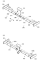
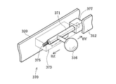
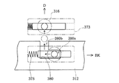
内枠30を固定した後に、レバー316を図1の矢印D方向に操作すれば、内フレーム320内に固定された状態の内枠30を180度反転することができる。図1では、内フレーム320と外フレーム312とは特に固定されておらず、レバー316はいつでも矢印D方向に移動できるものとして図示したが、作業中に内フレーム320が回転しないように、固定機構を設けることができる。固定機構370の一例を図12に示した。図示するように、この固定機構370は、レバー316が固定されたロック杆371と、ロック杆371を内フレーム320に沿って移動可能に保持する保持部材373、ロック杆371を、図示矢印BY方向に付勢するコイルバネ375と、外フレーム312側に固定されたロック筒377とから構成されている。なお、ロック筒377は、レバー316が図1矢印D方向に180度回転した場合にも、固定が行なわれるよう、外フレーム312の外側2カ所に設けられる。
【0071】
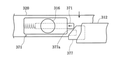
使用者が、レバー316を図12矢印BZ方向に移動すると、ロック杆371の先端は、コイルバネ375の付勢に抗して、保持部材373の内部に引き込まれる。したがって、ロック杆371とロック筒377との係合は解除され、使用者は、レバー316を持って、内フレーム320を自由に回転することができる。図1矢印D方向に内フレーム320を回転し、レバー316を内フレーム320の反対側に当接させると、ここで固定機構370のロック杆371は、ロック筒377に嵌合し、内フレーム320を外フレーム312に固定する。図12に示した構成では、ロック杆371は、コイルバネ375により常時付勢されており、保持部材373から突出しているので、ロック杆371の先端をロック筒377に嵌合する際には、レバー316を矢印BZ方向に一旦移動しなければならないが、ロック筒377の外形形状を、斜めにカットしておき、ロック杆371の先端が、この傾斜面377aに案内されて、保持部材373側に後退するようにしても良い。
【0072】
この他、固定機構としては、種々の構成が採用可能である。例えば、ロック筒377に代えて、図14に示すように、外フレーム312側に、摺動溝380aと案内溝380bとからなる略「L」字形の溝380を設けた構成とすることもできる。図14に示した構成でも、レバー316は、コイルバネ375により、矢印BK方向に付勢されており、固定状態では、レバー316は、摺動溝380aに嵌り込んでいる。この状態では、レバー316を、図1矢印D方向に移動することはできず、内フレーム320は外フレーム312に固定されている。内フレーム320を回転する際には、レバー316を摺動溝380a矢印BL方向に移動し、案内溝380bに対応した場所まで移動する。この状態になれば、矢印D方向にレバー316を移動し、溝380からレバー316を離脱させ、内フレーム320を外フレーム312に対して自由に回転することができる。
【0073】
図12ないし図14に示した構成によれば、固定機構370を用いて、内フレーム320を外フレーム312に対して、少なくとも二つの位置で固定することができる。したがって、内フレーム320に固定した内枠30に対して作業を行なっている際に、内枠30が不慮に回転したりすることがなく、あるいはレバー316を引っかけて内フレーム320が動いてしまうといったことがない。この結果、作業の安定性、安全性を一層高めることができる。
【0074】
このような構成のパチンコ遊技機用治具310を用いた場合の作業の流れを、図7に戻って説明する。寝かせ装置150により、パチンコ遊技機用治具310の真上であって、パチンコ遊技機用治具310の内フレーム320に旧機80が重なる位置まで寝かした後、寝かせ装置150を操作して、旧機80を内フレーム320内に落とし込む。なお、旧機80に衝撃を与えないように、旧機80を内フレーム320内に昇降させる機構を設けても良いし、受け台325にラバーなどを貼って、衝撃を吸収するようにしても良い。
【0075】
このように、第一部品分離工程Q3に送り込まれた内枠30は、寝かせ装置150によってパチンコ遊技機用治具310の内フレーム320内に収納される。
この後、作業者がパチンコ遊技機用治具310を図7(B)に白抜きの矢印で示す方向に引っ張ると、パチンコ遊技機用治具310はレール72のローラ上を滑りながら引っ張り方向に移動する。従って、パチンコ遊技機用治具310を作業領域が十分に確保された位置まで簡単に移動することができる。
【0076】
この後、作業者は、内枠30が収納されたパチンコ遊技機用治具310のハンドル322を図1に示す矢印A方向に引き、ロック機構315の操作部315aを図1の矢印C方向に約90度回転することにより、内フレーム320内に内枠30を固定する。こうした固定後にレバー316を操作したときには、二本のレール72間において内フレーム320が回転する。従って、第一部品分離工程Q3における内枠30からの機構板50,遊技板40の取り外しや、内枠30からの各種部品31〜38の取り外しの際に、内枠30の表裏を反転させながら効率よく解体作業を行なうことができる。
【0077】
また、第二部品分離工程Q4領域におけるレール72上には、上記パチンコ遊技機用治具310とほぼ同様の構成を有し遊技板40に適合した大きさの回転台、上記パチンコ遊技機用治具310とほぼ同様の構成を有し機構板50に適合した大きさの回転台が、それぞれ配置される。従って、第二部品分離工程Q4における機構板50からの各種部品51〜56の取り外しや、遊技板40からの各種部品41〜48の取り外しの際に、機構板50や遊技板40の表裏を反転させながら効率よく解体作業を行なうことができる。
【0078】
このように、第一部品分離工程Q3および第二部品分離工程Q4に、手動で運搬機能を果たすレール72を設ける構成を採用しているので、旧機80からの分離に手間がかかる部品がある場合に、かかる部品の分離作業をレール72上で時間をかけて慎重に行なうことができる。
【0079】
以上説明したパチンコ遊技機用治具310を用いれば、パチンコ遊技機80の内枠30を容易に固定して、これを回転し、しかも180度回転した位置で固定して、部品を遊技板40や機構板50の裏表から取り外す作業を容易に行なうことができる。しかも、このパチンコ遊技機用治具310はレール72上を容易に移動できるので、作業位置を自由に設定することができる。解体という作業は、組み付けと比べると、例えばねじがはずれにくかったり、部品が壊れかけていたり等、慮外の時間がかかることがある。従って、等速で製品を搬送するロールコンベヤでは作業がしにくい場合があるが、本実施例のパチンコ遊技機用治具310を用いれば、作業の進行に合わせて自由に作業を進めることができ、好適である。
【0080】
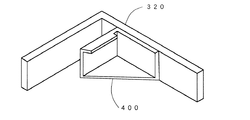
尚、上記実施例では、内枠30は、ハンドル322を操作して、内枠30の穿設孔30b,30dに係合ピン323a,324aを挿入して係合し、内枠30の他端をロック機構315により固定しているが、図15に示すように、内枠30の穿設孔30b,30dと係合ピン323a,324aとによる係合を利用しない手法も採用可能である。図15に示した例では、内フレーム320のロック機構315とは反対側の2カ所の隅部に、内枠30が挿入される枠係止ホルダ400が設けられている。この枠係止ホルダ400は、内枠30の幅とほぼ等しい内寸を有する略「コ」の字形をしており、ここに内枠30を差し込むことで、これを保持する。内枠30は、枠係止ホルダ400に一辺を差し込んだ後、他の辺を、上述した実施例と同様に、ロック機構315を用いて固定すれば良い。
【0081】
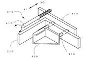
図15では、枠係止ホルダ400は、内枠30の隅部内側に固定するものとしたが、内枠30の固定をより確実にするために、図16に示すように、昇降機構410を有するものとしても良い。この場合、内枠30をはめ込む前に、枠係止ホルダ400は、外フレーム312側方向(図示矢印XO方向)に移動し、内枠30が挿入された後、内側方向(図示矢印XI方向)に移動して、内枠30を本来の上下方向から締め付けて固定する。尚、枠係止ホルダ400を昇降する昇降機構410は、回転する昇降杆412と、この昇降杆412の端部に形成されたねじ部と螺合する昇降プレート414と、この昇降プレート414の動きを内枠30の上下方向に規制する昇降案内軸416等から構成されている。昇降機構410の昇降は、図示しないモータなどにより、昇降杆412を正転方向または逆転方向に回転することにより行なわれる。尚、枠係止ホルダ400は、内枠30の一辺の上下2カ所に設けられていることから、昇降時における枠係止ホルダ400の移動方向は、合い向き合ったものとなるが、これは、昇降杆412の二つの端部に形成されるねじの一方を逆ねじにしておくことにより容易に実現することができる。
【0082】
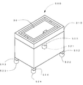
次に本発明の第2の実施例について説明する。図17は、第2実施例としての台車500の外観を示す斜視図である。図示するように、この台車500は、第1実施例のパチンコ遊技機用治具310と同一のパチンコ遊技機用治具310を備え、これを、キャスタ521ないし524を有する4本の脚部511ないし514で支えた構造を有する。尚、台車500の下部は、プレートにより覆われており、脚部511ないし514は、この内部に固定されている。
【0083】
かかる台車500は、パチンコ遊技機用治具310をレール72上を滑らせて搬送する代わりに、キャスタ521ないし524を利用して、台車毎自由に移動することができる。この結果、更に作業の自由度は向上する。即ち、内枠30をパチンコ遊技機用治具310に固定し、台車500ごと所望の位置に移動して解体作業を行なうことができる。しかも、台車500を用いれば、解体作業の途中で問題が生じたような場合、この内枠30を固定した台車500をそのままラインの脇によけて他の台車に固定された内枠30の解体作業を行なうことができるなど、作業の自由度を一層高めることができる。こうした点で極めて有効である。
【0084】
次に本発明の第3実施例について説明する。第3実施例の作業用台車500Aは、第2実施例の台車500において、パチンコ遊技機用治具310の外フレーム312にもう一つの回転軸を設け、図18に示すように、固定した内枠30ごと、いわゆる仰角を自由に設定できるものとしても良い。図18に示した例では、パチンコ遊技機用治具310は、台車500Aの両側部から上方に突きだした左右2本のアーム551,552により、回転自在に保持されており、しかもこの回転軸には、固定用ハンドル555が設けられている。従って、作業者は、パチンコ遊技機用治具310を、図示矢印FもしくはE方向に回転して、作業者に対して所望の角度とした後、固定用ハンドル555を締めて、パチンコ遊技機用治具310を固定する。その後は、既述した他の実施例同様、パチンコ遊技機用治具310に対して内枠30を回転し、その表面や裏面から、種々の部品を取り外し、解体作業を行なう。
【0085】
この作業用台車500Aによれば、解体の対象となっている内枠30を、作業者に対して適切な仰角に傾けて作業することができ、しかもその角度で、内枠30を内フレーム320ごと回転して、少なくとも内枠30の裏表から、解体作業を進めることができるという利点が得られる。尚、実施例で用いた構成では、内フレーム320は、180度回転したいずれかの位置でしか固定できないが、固定用ハンドルを設けて自由な回転位置で固定できるようにすることは容易である。また、例えば外周に15度おきにくぼみを有する節度板を内フレーム320の回転軸に固定し、この節度板の外周にバネにより押しつけられたレバーを設けて節度機構を構成し、内フレーム320を15度毎に固定する構成を採用することも可能である。この場合には、内フレーム320を、15度おきに自由に固定することができ、また自由に他の角度に変更することができ、作業の自由度を一層高めることができる。
【0086】
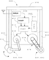
次に、本発明の第4の実施例として、自走式の作業用台車600について説明する。図19は、この実施例の作業用台車600を示す説明図である。図示するように、この作業用台車は、図18に示した作業用台車500とほぼ同一の構成を有するが、本体610の内部に、バッテリ612、ドライバ613、主モータ614、駆動機構616、従モータ618、無線装置620、制御装置622等を備える点で異なる。また、4本の脚部631ないし634のうちの二つの脚部631および632の先端には、キャスタに代えて、駆動輪641および642が設けられており、主モータ614の動力を駆動機構616を介して受け、作業用台車600を自走させることができる。他の二本の脚部633および633の先端にはキャスタ643および644が設けられている。このキャスタ643およひ644は、その方向が、従モータ618により調整可能となっている。
【0087】
この作業用台車600は、外部のコントローラ(例えばパチンコ遊技機製造システム10全体を管理するコントローラ)からの指示を無線装置620を介して受け取り、これを制御装置622で解析し、ドライは613を介して主モータ614および従モータ618を駆動して、作業用台車600を所望の方向に移動する。従って、作業者は、台車を自分の力で移動する必要がなく、例えば寝かせ装置を利用して内枠30を作業用台車600に設けられたパチンコ遊技機用治具310に取り付けられると、自走して、作業者のところまで到達したり、解体作業が終わって作業者がこれをコントローラに報告すると、自走して次の作業位置まで移動すると言ったことが可能である。尚、作業用台車600の移動は、この実施例では、コントローラにより指示するものとしたが、床面に、作業用台車600の移動をガイドするガイド部材(レール、光学的にガイド、あるいは磁気誘導用ガイドなど)を敷設し、作業用台車の搬送を、このガイド部材に沿って行なうものとすることも、作業の安全性を高める上で好適である。
【0088】
上述した各実施例では、パチンコ遊技機用治具310に、モータなどのアクチュエータを搭載し、内フレーム320の回転も、このアクチュエータを駆動して行なうことが考えられる。アクチュエータとして、保持用トルクの高いステッピングモータなどを利用すれば、回転した後の停止位置で内フレーム320を固定することは容易である。従って、内フレーム320を自由な位置で止めることができ、作業性の向上に資することができる。
【0089】
以上本発明のいくつかの実施例について説明したが、本発明はこれらの実施例に限定されるものではなく、本発明の要旨を逸脱しない範囲内において、種々なる態様で実現できることはもちろんである。例えば、パチンコ遊技機用治具310の用途は、パチンコ遊技機の解体に限定されるものではなく、パチンコ遊技機の組立に利用することも可能である。また、内フレームの外フレームに対する回転軸は一軸に限定されるものではなく、直交する二つの軸に対して回転可能とすることもできる。この場合には、内枠の上下を簡単に入れ替えることができ、部品の形状などによっては、組立や解体を容易にすることができる。更に、上記実施例では、内枠を固定するものとしたが、パチンコ遊技機の部材であれば、機構板や遊技板を固定するものとすることもできる。もとより外枠ごと固定するものとしても良い。
【図面の簡単な説明】
【図1】本発明の第1実施例としてのパチンコ遊技機用治具310の外観を示す斜視図である。
【図2】本発明の第1実施例であるパチンコ遊技機製造システム10の概要を示す説明図である。
【図3】収納ラックPB1および収納具PB3,PB4,PB5に収納される新規部品Vの一覧を示す説明図である。
【図4】パチンコ遊技機を構成する各種部品の取り付け関係を示す説明図である。
【図5】収納ラックQB1,QB2および収納具QB3,QB4,QB5に収納される既使用部品Mの一覧を示す説明図である。
【図6】解体ラインQLにおいて旧機80から外枠22が取り外される様子を示す説明図である。
【図7】解体ラインQLにおいて、遊技板40および機構板50と一体の内枠30が寝かせ装置150からレール72上のパチンコ遊技機用治具310に移される様子を示す説明図である。
【図8】パチンコ遊技機用治具310の上面を示す説明図である。
【図9】パチンコ遊技機用治具310における軸体330A周辺の縦断面を示す説明図である。
【図10】パチンコ遊技機用治具310側面における軸体330Aの装着部の様子を示す説明図である。
【図11】係合ピン323a,324aを移動する機構の概要を示す斜視図である。
【図12】内フレーム320を固定する固定機構370の一例を示す斜視図である。
【図13】同じく固定機構370の変形例を示す説明図である。
【図14】同じく固定機構370の他の実施例を示す説明図である。
【図15】第1実施例の第1の変形例を示す説明図である。
【図16】第1実施例の第2の変形例を示す説明図である。
【図17】本発明の第2の実施例としての作業用台車500を示す説明図である。
【図18】本発明の第3の実施例としての作業用台車500Aを示す説明図である。
【図19】本発明の第4の実施例としての作業用台車600を示す説明図である。
【符号の説明】
10…パチンコ遊技機製造システム
22…外枠
30…内枠
30b,30d,30g…穿設孔
31,45…表示ランプ
31…表示ランプ
32…ガラス扉
33…装飾板
34…上皿
35…下皿
36…発射ハンドル
37…打球発射回路基板
38…発射モータ
40…遊技板
41…誘導レール
42…障害釘
43…風車
44…入賞口
45…表示ランプ
46…球誘導ユニット
47…入賞検出手段
48…図柄表示装置
50…機構板
51…発射レール
52…球タンク
53…タンクレール
54…入出力基板
55…制御回路ボックス
56…払出し装置
70…ローラコンベヤ
70a1…コンベヤ
70a2…コンベヤ
72…レール
76…検査ボード
78…作業台
80…パチンコ遊技機(旧機)
90…ローラコンベヤ
150…寝かせ装置
151…本体
155…昇降アーム部
241…台座
242…誘導レール
243…押圧装置
310…パチンコ遊技機用治具(固定用治具)
311…受け台
312…外フレーム
313…凹所
314L,314R…切欠部
315…ロック機構
315a…操作部
315b…アーム
315c…押圧体
315d…軸支部
316…レバー
320…内フレーム
321…貫通孔
322…ハンドル
323,324…機構部
323a,324a…係合ピン
325…受け台
326,327…プレート
328…皿ばね
330A,330B…軸体
331…ベアリング
332…プレート
333…座金
334…ナット
341,342…クランク機構
343…連携軸
345a〜345d…ねじ
346…上方連携軸
347…下方連携軸
350…支持ガイド
351…上方昇降杆
352…下方昇降杆
361,362…可動板
371…ロック杆
373…保持部材
375…コイルバネ
377…ロック筒
380…溝
380a…摺動溝
380b…案内溝
400…枠係止ホルダ
410…昇降機構
412…昇降杆
414…昇降プレート
416…昇降案内軸
500…作業用台車
500A…作業用台車
511〜514…脚部
521〜524…キャスタ
551,552…アーム
555…固定用ハンドル
600…作業用台車
610…本体
612…バッテリ
613…バッテリ
614…主モータ
616…駆動機構
618…従モータ
620…無線装置
622…制御装置
631〜634…脚部
641,642…駆動輪
643,644…キャスタ[0001]
BACKGROUND OF THE INVENTION
The present invention relates to a pachinko gaming machine jig and a pachinko gaming machine carriage, and further relates to a pachinko gaming machine working method and working system using the jig.
[0002]
[Prior art]
Pachinko machines use a combination of different materials such as wood, synthetic resin, metal, and glass, so if they are discarded after use, the burden on the environment is large. Therefore, by disassembling, sorting and disposal, partial reuse of parts, and the like are performed. The parts are removed from the frame constituting the pachinko gaming machine, and further separated according to materials such as metal, plastic, wood, glass, etc., so that processing such as crushing or melting is facilitated, and it is performed for disposal or recycling. (See, for example, JP-A-9-122630).
[0003]
In such dismantling, removal of a motor, a control panel, glass, or the like from a pachinko gaming machine is usually performed manually by placing the pachinko gaming machine on a work table or the like.
[0004]
[Problems to be solved by the invention]
However, in recent pachinko machines, the configuration on the back side of the game board has become complicated, and if you try to remove the parts from the pachinko machine, you will have to take the hassle of turning the pachinko machine upside down, standing up, laying it down, etc. There was a problem that it took. There was a problem that it was extremely inefficient to work with the collected pachinko machine on the workbench.
[0005]
Such a problem actually occurred even when a pachinko gaming machine was assembled manually. As the configuration of pachinko machines becomes complex, if you try to assemble a pachinko machine without using an automatic machine, the pachinko machine will be turned over, laid, or stood up to install various parts. Annoying work was necessary.
[0006]
The present invention has the following configuration for the purpose of solving the above-mentioned problems and preparing a dismantling or assembling operation of a used pachinko gaming machine.
[0007]
[Means for solving the problems and their functions and effects]
The jig for pachinko gaming machine of the present invention is
A jig used for assembly or disassembly of a pachinko machine,
An inner frame to which the pachinko machine is fixed,
An outer frame that rotatably supports the inner frame;
in front The frame , Determined for the
The main point is that
[0008]
Such a jig is used for assembling or disassembling a pachinko gaming machine, of which a pachinko gaming machine is fixed to a frame. At this time, the frame has two or more relative to the outer frame that rotatably supports the frame. rotation Can be fixed in position. Therefore, the pachinko gaming machine can be rotated together with the inner frame, and it is not necessary to turn the pachinko gaming machine upside down or lie down on the work table. As a result, the assembly and disassembly work of the pachinko gaming machine becomes extremely easy.
[0009]
In such a pachinko gaming machine jig, the inner frame can be rotated with respect to the outer frame by at least 180 degrees while the pachinko gaming machine is fixed. If it can be rotated at least 180 degrees, it is possible to work from the same direction with respect to the back and front of the pachinko gaming machine, and the assembly or disassembly work becomes easy.
[0010]
In such a pachinko gaming machine jig,
The fixing mechanism is
First fixing means for holding and fixing the frame of the pachinko gaming machine from both side ends of one side of the frame;
A second fixing means for holding and fixing the frame body from one side to the other side of the pachinko gaming machine on one side opposite to the side;
Can be provided.
In this case, the frame is clamped from both sides of the one side by the first fixing means, and the frame is clamped and fixed from the front-rear direction by the second fixing means. The fixed position can be accurately positioned in at least two directions. This effect is especially true when using this pachinko machine jig at a certain position and then moving to another position and then working again, the position of the pachinko machine fixed to the jig changes. There is no saying that it will interfere with work. In addition, since the frame of the pachinko gaming machine is sandwiched from both ends of the side on one side and from the front-rear direction on the opposite side, when the pachinko gaming machine is rotated together with the inner frame, Pachinko machines will not drop out.
[0011]
Here, the frame fixed by the first and second fixing means can be any one of the outer frame, the inner frame, and the front frame of the pachinko gaming machine. When fixing any of these frames, it is easy to work on components attached to the frame.
[0012]
Further, in such a pachinko gaming machine jig, the inner frame is provided with an engaging portion on one side of which the corresponding side of the frame of the pachinko gaming machine is engaged, and one side opposite to the one side. A mounting member for mounting a corresponding side of the frame of the pachinko gaming machine, and a clamp mechanism for sandwiching and fixing the one side of the pachinko gaming machine between the mounting member It can be. If such a configuration is adopted, the pachinko gaming machine can be easily fixed to the inner frame simply by operating the clamp mechanism. In addition, since one side of the frame of the pachinko gaming machine is sandwiched and fixed on the mounting member by the clamp mechanism, the frame and thus the pachinko gaming machine will not be lifted.
[0013]
In the above axis, the inner frame rotates relative to the outer frame. Therefore, it is also preferable to provide the inner frame with a handle for rotating the inner frame in order to improve workability. Further, by operating this handle, the inner frame can be fixed so as not to rotate with respect to the outer frame, and the fixing can be released. In this case, since the fixation and the release can be performed only by the operation of the handle, there is an advantage that the operation becomes easy. Such fixing and releasing means can be provided in at least two locations corresponding to the fixing position of the inner frame. At this time, the means for fixing and releasing includes an engaging portion connected to the handle, a moving mechanism for holding the handle together with the engaging portion so as to be movable in a direction crossing the rotation direction of the inner frame, By engaging with the mating part, a fixing part for fixing the engaging part is provided, and by moving the handle in the crossing direction, the engaging part is detached from the fixing part and the inner frame can be rotated. The inner frame is rotated, and the engaging portion of the handle is engaged with the fixing portion of the means for fixing and releasing at the rotational position, thereby fixing the inner frame. . In this case, the handle movement direction when fixing or releasing the rotation of the inner frame is a direction that intersects the rotation direction of the inner frame, so that an operator may accidentally touch the handle. Even if you do, the inner frame will not rotate.
[0014]
The pachinko gaming machine jig includes an electric motor, a transmission mechanism that transmits the rotation of the electric motor, and a rotation mechanism that rotates the inner frame to a desired position by power transmitted through the transmission mechanism. It may be provided. By doing so, the inner frame and the pachinko gaming machine fixed to the inner frame can be rotated using the electric motor, so that the operation is simple and good.
[0015]
In such a jig, it is also desirable to provide a fixture for fixing the rotated inner frame at a predetermined position. This is because when the work is performed, the work is facilitated if the inner frame is fixed at a predetermined position. Such a fixed position may be one or a plurality of predetermined positions, or may be fixed at an arbitrary position.
[0016]
Such a jig can be made of various materials, but when handling a machine having a weight of around 20 kilograms such as a pachinko machine, the inner frame and the outer frame may be made of aluminum. This is desirable from the viewpoint of achieving both weight reduction and rigidity of the entire jig. Of course, stainless steel, duralumin, and other light alloys may be used. In the case where durability is not so important, it is also possible to use wooden or synthetic resin.
[0017]
A pachinko machine cart can be configured using the jig. That is, the pachinko machine cart is
A pachinko gaming machine jig comprising at least one configuration of the aforementioned pachinko gaming machine jig,
A mounting table with wheels for mounting the pachinko machine jig;
The gist is that
[0018]
Since this carriage has a mounting table with wheels, it can be easily moved while the pachinko gaming machine jig is mounted (therefore, the pachinko gaming machine is fixed). As a result, for example, when the disassembly work or assembly work is configured as a combination of specific places where specific work is performed, the pachinko gaming machine can be freely moved between these places while being fixed. The work of disassembly and assembly can be easily performed.
[0019]
Furthermore, if an electric motor that rotationally drives the wheels is provided, the carriage can be self-propelled or moved with a small force, which is preferable.
[0020]
In addition, a work system for disassembling and assembling a new and useful pachinko gaming machine can be configured by using the above-described pachinko gaming machine jig. In other words, this pachinko machine system is
A work line for performing assembly or disassembly work while the pachinko gaming machine is erected,
One of the above-mentioned jigs for pachinko machines,
Transfer means for transferring the pachinko gaming machine from the work line to the pachinko gaming machine jig;
Jig transporting means for transporting the pachinko gaming machine jig in which the pachinko gaming machine is fixed to the inner frame in a state in which the pachinko gaming machine can be rotated together with the inner frame;
The gist is that
[0021]
According to such a work system, by using the above-described pachinko gaming machine jig in the work line, it is possible to easily realize the rotation of the pachinko gaming machine in the work line, and from the front and back of the pachinko machine. Facilitates installation and disassembly of parts.
[0022]
As another work system of the present invention,
A system for assembling or dismantling pachinko machines,
An inner frame to fix the pachinko machine,
An outer frame for rotatably holding the inner frame;
Fixing means for fixing the inner frame to the outer frame at two or more different rotational positions;
A pachinko machine jig equipped with
Conveying means for moving the pachinko gaming machine jig to an assembly or dismantling work site;
You can also think of a configuration with
[0023]
Even in this configuration, by fixing the pachinko gaming machine to the inner frame of this jig in the work, the pachinko gaming machine can be easily rotated, and parts can be easily mounted and disassembled from the front and back of the pachinko gaming machine. can do.
[0024]
An invention of a method for assembling or disassembling a pachinko gaming machine using the fixing jig described above can be configured. That is, such a work method is
A method of assembling or disassembling parts for a pachinko machine,
Fix the pachinko machine to the inner frame that is pivotally supported with respect to the outer frame provided in the fixing jig,
Fixing the inner frame to the outer frame at a first rotational position;
For the pachinko gaming machine fixed in the first position, perform a first work of attaching or dismantling parts,
After completion of the first operation, the inner frame is rotated with respect to the outer frame, and is fixed at a second position different from the first position;
Performing a second operation of attaching or disassembling other parts to the pachinko gaming machine fixed in the second position.
Is the gist.
[0025]
According to this working method, the pachinko gaming machine fixed to the inner frame of the fixing jig is fixed at the first rotation position by rotating the inner frame with respect to the outer frame, where the pachinko gaming machine A first operation of attaching or dismantling the parts is performed. After completion of this operation, the inner frame is rotated with respect to the outer frame and fixed at a second position different from the first position, and a second disassembly operation for attaching or disassembling other components is performed here. Accordingly, the pachinko gaming machine is fixed at least at the first and second positions by using a fixing jig having an inner frame that is rotatable with respect to the outer frame, and easily at each position with respect to the pachinko gaming machine. Parts can be attached to or dismantled.
[0026]
Here, the second operation at the second position can be an operation of attaching or disassembling the parts from different sides of the front and back of the pachinko gaming machine with respect to the first position. By rotating, the front and back of the pachinko gaming machine can be easily positioned in front of the operator, so that work efficiency can be improved.
[0027]
DETAILED DESCRIPTION OF THE INVENTION
Embodiments of the present invention will be described based on examples. FIG. 1 is a perspective view illustrating a schematic configuration of a pachinko
[0028]
FIG. 2 is an explanatory diagram showing an outline of the pachinko gaming
[0029]
(1) Production line PL and its work contents:
First, a manufacturing line PL for assembling various parts necessary for manufacturing a pachinko gaming machine will be briefly described with reference to FIG. The production line PL is constructed so that parts are sequentially attached along the
[0030]
In the game board / mechanism board assembly process P1, as shown in FIG. 4, the
[0031]
In the inner frame assembling process P2, the
[0032]
Then, next, the process proceeds to the operation check / adjustment step P3, where the operation check and adjustment work of various components assembled to the
[0033]
Those determined to be non-defective in the operation check / adjustment process P3 are transferred to the next outer frame assembly process P4. In the outer frame assembly process P4, the
[0034]
(2) Demolition line QL:
In the above, each process P1-P5 of the production line PL was demonstrated. Next, the disassembly line QL and the parts inspection / adjustment lines TAL and TBL which are another line constituting the pachinko gaming
[0035]
As shown in FIG. 2, the disassembly line QL is provided on the opposite side of the production line PL with the component inspection / adjustment lines TAL and TBL interposed therebetween. The dismantling line QL includes a
[0036]
The flow work performed on the
[0037]
In FIG. 2, after the
[0038]
In FIG. 2, the position of the operator in each process Q1, Q2, Q3, Q4 is shown using double circles. A storage rack QB1, a storage rack QB2, a storage tool QB3, a storage tool QB4, and a storage tool QB5 are provided in the vicinity of the operator's position in each of the processes Q1, Q2, Q3, and Q4. In the storage racks QB1, QB2 and the storage tools QB3, QB4, QB5, parts separated from the
[0039]
Casters are provided on the legs of the storage racks QB1, QB2 and storage tools QB3, QB4, QB5. Therefore, the operator pushes the storage racks QB1, QB2 and the storage tools QB3, QB4, QB5 by hand, thereby moving the storage racks QB1, QB2, and the storage tools QB3, QB4, QB5 to the parts inspection / adjustment line TBL and the production line PL. Can be moved easily. Of course, the storage racks QB1 and QB2 and the storage tools QB3, QB4 and QB5 may be moved by other transporting devices such as a lift machine. It is also possible to automate the operation by controlling the operation of the transport device relating to the collection and movement of the storage racks QB1, QB2 and the storage tools QB3, QB4, QB5.
[0040]
(3) Parts inspection / adjustment lines TAL, TBL:
As shown in FIG. 2, in the region between the outer frame separation step Q1 of the dismantling line QL and the outer frame assembly step P4 of the production line PL, the used parts M (specifically separated in the outer frame separation step Q1) Specifically, a component inspection / adjustment line TAL for inspecting or adjusting the outer frame 22) is provided. The component inspection / adjustment line TAL includes an
[0041]
Further, in the region between the first part separation process Q3 and the second part separation process Q4 of the dismantling line QL and the inner frame assembly process P2 and the game board / mechanism board assembly process P1 of the production line PL, each part separation process A parts inspection / adjustment line TBL for inspecting or adjusting the used parts M separated in Q3 and Q4 is provided. The parts inspection / adjustment line TBL includes a work table 78 for placing the used parts M to perform inspection work and adjustment work. The work performed on the work table 78 is divided into two processes, an appearance inspection / adjustment process TB1 and a function inspection / adjustment process TB2. As shown by the white arrow in FIG. 2, first, inspection or adjustment of the appearance of the used part M is performed in the appearance inspection / adjustment process TB1, and then, the used part M is checked in the function inspection / adjustment process TB2. Inspection or adjustment of function is performed.
[0042]
(4) Work contents in the dismantling line QL:
The contents of the work performed in each process Q1, Q2, Q3, Q4 of the dismantling line QL will be specifically described below. First, in the outer frame separation step Q1, the
[0043]
As shown in FIG. 6B, the
[0044]
As shown in FIG. 6A, a
[0045]
As shown in FIG. 6A, the
The
[0046]
On the other hand, the
[0047]
When the
[0048]
If the operation of various parts is in an inappropriate state as a shipped product, adjustments are made by reworking. For example, when it is confirmed that the ballistic force of the game ball to be fired is weak, the play range of the firing handle 36 is adjusted. If a ball clogging occurs in the payout device 56 when paying out a prize ball, adjustment is made so that the ball clogging does not occur by cleaning the payout device 56 or the like.
[0049]
The
[0050]
On the other hand, when it is confirmed whether or not the
Regarding the subsequent processes, the
[0051]
As shown in FIG. 7A, the laying
[0052]
In this way, when the
[0053]
As shown in FIG. 1, the pachinko
The inside of the
[0054]
As shown in FIGS. 2 and 8, the
[0055]
A connection structure of the
[0056]
In the space between the
By mounting the
[0057]
As shown in FIG. 9, a through
[0058]
On the other hand, a
[0059]
Therefore, in FIG. 1, when the
[0060]
As shown in FIGS. 1 and 8, two
[0061]
A
[0062]
1 and 8 show a state in which the
[0063]
The structure of the
[0064]
When the
[0065]
By this engagement, the left half of the
[0066]
In addition, what is necessary is just to raise the
In this case, the upper elevating
[0067]
In the vicinity of the center of the other long side of the inner frame 320 (the long side that is separated from the
[0068]
1 and 8 show a state where the
When the
[0069]
Therefore, in the pachinko
[0070]
If the
[0071]
When the user moves the
[0072]
In addition, various configurations can be adopted as the fixing mechanism. For example, instead of the
[0073]
According to the configuration shown in FIGS. 12 to 14, the
[0074]
The work flow when the pachinko
[0075]
Thus, the
Thereafter, when the operator pulls the pachinko
[0076]
Thereafter, the operator pulls the
[0077]
Further, on the
[0078]
Thus, since the structure which provides the
[0079]
If the pachinko
[0080]
In the above embodiment, the
[0081]
In FIG. 15, the
[0082]
Next, a second embodiment of the present invention will be described. FIG. 17 is a perspective view showing an appearance of a
[0083]
Such a
[0084]
Next, a third embodiment of the present invention will be described. The working cart 500A of the third embodiment is the same as the
[0085]
According to this working cart 500A, the
[0086]
Next, a self-propelled working
[0087]
The
[0088]
In each of the embodiments described above, it is conceivable that an actuator such as a motor is mounted on the pachinko
[0089]
Although several embodiments of the present invention have been described above, the present invention is not limited to these embodiments, and can of course be implemented in various modes without departing from the gist of the present invention. . For example, the use of the pachinko
[Brief description of the drawings]
FIG. 1 is a perspective view showing an appearance of a pachinko
FIG. 2 is an explanatory diagram showing an overview of a pachinko gaming
FIG. 3 is an explanatory diagram showing a list of new parts V stored in the storage rack PB1 and storage tools PB3, PB4, and PB5.
FIG. 4 is an explanatory view showing a mounting relationship of various parts constituting the pachinko gaming machine.
FIG. 5 is an explanatory diagram showing a list of used parts M stored in the storage racks QB1, QB2 and storage tools QB3, QB4, QB5.
FIG. 6 is an explanatory diagram showing a state where the
7 is an explanatory view showing a state in which the
FIG. 8 is an explanatory view showing the upper surface of a
FIG. 9 is an explanatory view showing a longitudinal section around a
FIG. 10 is an explanatory view showing a state of the mounting portion of the
FIG. 11 is a perspective view showing an outline of a mechanism for moving
12 is a perspective view showing an example of a
13 is an explanatory view showing a modified example of the
14 is an explanatory view showing another embodiment of the
FIG. 15 is an explanatory diagram showing a first modification of the first embodiment.
FIG. 16 is an explanatory diagram showing a second modification of the first embodiment.
FIG. 17 is an explanatory view showing a working
FIG. 18 is an explanatory view showing a working carriage 500A as a third embodiment of the present invention.
FIG. 19 is an explanatory view showing a working
[Explanation of symbols]
10. Pachinko machine manufacturing system
22 ... Outer frame
30 ... Inner frame
30b, 30d, 30g ... drilling holes
31, 45 ... Indicator lamp
31 ... Indicator lamp
32 ... Glass door
33 ... Decorative plate
34 ... Upper plate
35 ... lower plate
36 ... Launch handle
37 ... Hit ball launch circuit board
38 ... Launch motor
40 ... Game board
41 ... guide rail
42 ... Nails with obstacles
43 ... Windmill
44 ... Winner of a prize
45 ... Indicator lamp
46 ... Sphere guidance unit
47. Winning detection means
48 ... Symbol display device
50 ... Mechanism plate
51 ... Launch rail
52 ... Sphere tank
53 ... Tank rail
54 ... I / O board
55 ... Control circuit box
56. Dispensing device
70 ... Roller conveyor
70a1 ... conveyor
70a2 ... conveyor
72 ... Rail
76 ... Inspection board
78 ... Workbench
80 ... Pachinko machine (old machine)
90 ... Roller conveyor
150 ... Laying device
151 ... Body
155 ... Elevating arm part
241: Pedestal
242 ... Guide rail
243 ... Pressing device
310 ... Jig for pachinko machine (fixing jig)
311 ... cradle
312 ... Outer frame
313 ... recess
314L, 314R ... Notch
315 ... Lock mechanism
315a: Operation unit
315b ... arm
315c ... Pressing body
315d ... Shaft support
316 ... Lever
320 ... Inner frame
321 ... through hole
322 ... Handle
323, 324 ... Mechanism part
323a, 324a ... engaging pins
325 ... cradle
326,327 ... Plate
328 ... Disc spring
330A, 330B ... shaft body
331 ... Bearing
332 ... Plate
333 ... Washer
334 ... Nut
341, 342 ... Crank mechanism
343 ... Cooperation axis
345a-345d ... screw
346 ... Upward cooperation axis
347 ... Downward coordination axis
350 ... Support guide
351 ... Up and down lift
352 ... Lower lift
361, 362 ... movable plate
371 ... Rock 杆
373 ... Holding member
375 ... Coil spring
377 ... Lock cylinder
380 ... Groove
380a ... Sliding groove
380b ... Guide groove
400 ... Frame locking holder
410 ... Elevating mechanism
412 ... Lifting bowl
414 ... Elevating plate
416 ... Elevating guide shaft
500 ... Work cart
500A ... Work cart
511-514 ... Legs
521-524 ... Casters
551, 552 ... Arm
555 ... Fixing handle
600 ... Work cart
610 ... Body
612 ... Battery
613 ... Battery
614 ... Main motor
616 ... Drive mechanism
618 ... Slave motor
620 ... Wireless device
622 ... Control device
631-634 ... Leg
641, 642 ... Drive wheels
643, 644 ... Casters
Claims (12)
パチンコ遊技機が固定される内フレームと、
該内フレームを回転可能に軸支する外フレームと、
前記内フレームを、前記外フレームに対して定まる2以上の回転位置で固定可能な固定機構と
を備えたパチンコ遊技機用治具。A jig used for assembly or disassembly of a pachinko machine,
An inner frame to which the pachinko machine is fixed,
An outer frame that rotatably supports the inner frame;
The pre Symbol frame, pachinko machines jig with a fixed anchoring mechanism in two or more rotational positions determined with respect to the outer frame.
前記内フレームは、
その一辺に、前記パチンコ遊技機の枠体の対応する一辺が係合される係合部を備えると共に、
該一辺とは反対側の一辺に、前記パチンコ遊技機の枠体の対応する一辺を載置する載置部材と、該載置部材との間に、該パチンコ遊技機の該一辺を挟み込んで固定するクランプ機構とを備えた
パチンコ遊技機用治具。 A jig for a pachinko gaming machine according to claim 1,
The inner frame is
On one side thereof is provided with an engaging portion to which a corresponding side of the frame of the pachinko gaming machine is engaged,
The one side of the pachinko gaming machine is sandwiched between the mounting member for mounting the corresponding side of the frame of the pachinko gaming machine on one side opposite to the one side and the mounting member. A pachinko machine jig equipped with a clamping mechanism.
前記内フレームは、前記パチンコ遊技機を固定したまま、少なくとも180度、前記外フレームに対して回転可能であるパチンコ遊技機用治具。 A jig for a pachinko gaming machine according to claim 1,
The inner frame is a jig for a pachinko gaming machine that can rotate with respect to the outer frame at least 180 degrees while the pachinko gaming machine is fixed.
電動機と、該電動機の回転を伝達する伝達機構と、該伝達機構を介して伝達される動力により前記内フレームを所望の位置まで回転する回転機構と
を備えたパチンコ遊技機用治具。 A jig for a pachinko gaming machine according to claim 1,
A pachinko gaming machine jig comprising: an electric motor; a transmission mechanism that transmits rotation of the electric motor; and a rotation mechanism that rotates the inner frame to a desired position by power transmitted through the transmission mechanism.
前記請求項1ないし請求項6のいずれかに記載のパチンコ遊技機用治具と、
該パチンコ遊技機用治具を載置する車輪付きの載置台と
を備えたパチンコ遊技機用台車。 A pachinko machine cart,
A jig for a pachinko gaming machine according to any one of claims 1 to 6 ,
A pachinko gaming machine carriage comprising: a wheeled mounting table on which the pachinko gaming machine jig is mounted.
前記パチンコ遊技機を立設したまま組立または解体作業を行なう作業用ラインと、
前記請求項1ないし請求項8のいずれかに記載のパチンコ遊技機用治具と、
前記作業用ラインから前記パチンコ遊技機を前記パチンコ遊技機用治具に移し替える移行手段と、
該パチンコ遊技機を前記内フレームに固定した前記パチンコ遊技機用治具を、前記内フレームごと前記パチンコ遊技機を回転可能な状態で搬送する治具搬送手段と
を備えたパチンコ遊技機作業システム。 A system for assembling or dismantling pachinko machines,
A work line for performing assembly or disassembly work while the pachinko gaming machine is erected,
A jig for a pachinko gaming machine according to any one of claims 1 to 8 ,
Transfer means for transferring the pachinko gaming machine from the work line to the pachinko gaming machine jig;
A pachinko gaming machine working system comprising: jig transporting means for transporting the pachinko gaming machine jig in which the pachinko gaming machine is fixed to the inner frame in a state where the pachinko gaming machine can be rotated together with the inner frame.
パチンコ遊技機を、固定する内フレームと、
該内フレームを回転自在に保持する外フレームと、
前記内フレームを、前記外フレームに対して定まる2以上の回転位置で固定可能な固定機構と、
を備えたパチンコ遊技機用治具と、
該パチンコ遊技機用治具を組立または解体作業箇所まで移動する搬送手段と
を備えたパチンコ遊技機作業システム。A system for assembling or dismantling pachinko machines,
An inner frame to fix the pachinko machine,
An outer frame for rotatably holding the inner frame;
A fixing mechanism capable of fixing the inner frame at two or more rotational positions determined with respect to the outer frame;
A pachinko machine jig equipped with
A pachinko gaming machine working system comprising: a conveying means for moving the jig for pachinko gaming machines to an assembly or dismantling work site.
パチンコ遊技機を、固定用治具に設けられた外フレームに対して回転自在に軸支された内フレームに固定し、
該内フレームを前記外フレームに対して第1の回転位置で固定し、
該第1の位置に固定された前記パチンコ遊技機に対して、部品を取付または解体する第1の作業を行ない、
該第1の作業の完了後に、前記内フレームを前記外フレームに対して回転し、前記第1の位置とは異なる第2の位置に固定し、
該第2の位置に固定された前記パチンコ遊技機に対して、他の部品を取付または解体する第2の作業を行なう
パチンコ遊技機の作業方法。 A method of assembling or disassembling parts for a pachinko machine,
Fix the pachinko machine to the inner frame that is pivotally supported with respect to the outer frame provided in the fixing jig,
Fixing the inner frame to the outer frame at a first rotational position;
For the pachinko gaming machine fixed in the first position, perform a first work of attaching or dismantling parts,
After completion of the first operation, the inner frame is rotated with respect to the outer frame, and is fixed at a second position different from the first position;
A pachinko gaming machine working method for performing a second work of attaching or disassembling other components to the pachinko gaming machine fixed at the second position.
前記第2の位置での前記解体の処理は、前記第1の位置に対して、パチンコ遊技機の表裏の異なる側から前記部品を取付または解体する処理である作業方法。A working method of the pachinko gaming machine according to claim 11 ,
The dismantling process at the second position is a work method that is a process of attaching or disassembling the parts from different sides of the pachinko gaming machine with respect to the first position.
Priority Applications (1)
| Application Number | Priority Date | Filing Date | Title |
|---|---|---|---|
| JP2000388502A JP4580098B2 (en) | 2000-12-21 | 2000-12-21 | Pachinko machine jigs, pachinko machine carts, systems using these, and work methods |
Applications Claiming Priority (1)
| Application Number | Priority Date | Filing Date | Title |
|---|---|---|---|
| JP2000388502A JP4580098B2 (en) | 2000-12-21 | 2000-12-21 | Pachinko machine jigs, pachinko machine carts, systems using these, and work methods |
Publications (2)
| Publication Number | Publication Date |
|---|---|
| JP2002186716A JP2002186716A (en) | 2002-07-02 |
| JP4580098B2 true JP4580098B2 (en) | 2010-11-10 |
Family
ID=18855220
Family Applications (1)
| Application Number | Title | Priority Date | Filing Date |
|---|---|---|---|
| JP2000388502A Expired - Fee Related JP4580098B2 (en) | 2000-12-21 | 2000-12-21 | Pachinko machine jigs, pachinko machine carts, systems using these, and work methods |
Country Status (1)
| Country | Link |
|---|---|
| JP (1) | JP4580098B2 (en) |
Families Citing this family (2)
| Publication number | Priority date | Publication date | Assignee | Title |
|---|---|---|---|---|
| JP5897983B2 (en) * | 2012-05-11 | 2016-04-06 | 日本ぱちんこ部品株式会社 | Back panel unit assembly jig |
| JP5431616B1 (en) * | 2013-10-08 | 2014-03-05 | 小松貿易株式会社 | Automatic dismantling processing equipment for gaming machines |
Family Cites Families (1)
| Publication number | Priority date | Publication date | Assignee | Title |
|---|---|---|---|---|
| JPH0517103Y2 (en) * | 1988-03-28 | 1993-05-07 |
-
2000
- 2000-12-21 JP JP2000388502A patent/JP4580098B2/en not_active Expired - Fee Related
Also Published As
| Publication number | Publication date |
|---|---|
| JP2002186716A (en) | 2002-07-02 |
Similar Documents
| Publication | Publication Date | Title |
|---|---|---|
| US12110698B2 (en) | Systems and methods of producing components for use in the construction of modular building units | |
| JP6628534B2 (en) | Automatic assembly method and automatic assembly system | |
| US20080172983A1 (en) | System and method for the automated assembly of trusses | |
| EP3962686B1 (en) | Portable automated panel cutter | |
| CN101855040A (en) | screw fastening device | |
| JPH084272A (en) | Ceiling and wall interior construction equipment and its accessories | |
| JP4580098B2 (en) | Pachinko machine jigs, pachinko machine carts, systems using these, and work methods | |
| US20240246181A1 (en) | Mobile Fastener Machine Platform | |
| US12269146B2 (en) | Mobile and modular drill apparatus, components thereof, and methods of use | |
| JP6900010B2 (en) | Bogie | |
| CN102554611B (en) | Machine tool assembling apparatus and method of assembling machine tool using machine tool assembling apparatus | |
| JP6819536B2 (en) | Fastening device | |
| JP4580096B2 (en) | Game machine manufacturing system | |
| JP2020200593A (en) | Gripping device, gripping transportation device, and transportation/installation method using gripping device | |
| CN213084469U (en) | Conveying device | |
| CN214086571U (en) | Material grabbing mechanism and feeding system thereof | |
| WO2023125167A1 (en) | Building construction robot | |
| CN205150275U (en) | Mobile Aided Positioning System for Crawling Robots | |
| CN223507147U (en) | A lifting fan impeller auxiliary installation device | |
| CN201998083U (en) | Workpiece overturning device | |
| CN223950186U (en) | A cage-type flipping device | |
| CN117102681B (en) | Continuous laser marking equipment | |
| JPH046614B2 (en) | ||
| CN111746613A (en) | Reinforcing bar conveyer for building | |
| CN120364427A (en) | Quartz stone plate production line loading and conveying device |
Legal Events
| Date | Code | Title | Description |
|---|---|---|---|
| A621 | Written request for application examination |
Free format text: JAPANESE INTERMEDIATE CODE: A621 Effective date: 20070912 |
|
| A131 | Notification of reasons for refusal |
Free format text: JAPANESE INTERMEDIATE CODE: A131 Effective date: 20100511 |
|
| A521 | Request for written amendment filed |
Free format text: JAPANESE INTERMEDIATE CODE: A523 Effective date: 20100709 |
|
| TRDD | Decision of grant or rejection written | ||
| A01 | Written decision to grant a patent or to grant a registration (utility model) |
Free format text: JAPANESE INTERMEDIATE CODE: A01 Effective date: 20100810 |
|
| A01 | Written decision to grant a patent or to grant a registration (utility model) |
Free format text: JAPANESE INTERMEDIATE CODE: A01 |
|
| A61 | First payment of annual fees (during grant procedure) |
Free format text: JAPANESE INTERMEDIATE CODE: A61 Effective date: 20100827 |
|
| FPAY | Renewal fee payment (event date is renewal date of database) |
Free format text: PAYMENT UNTIL: 20130903 Year of fee payment: 3 |
|
| R150 | Certificate of patent or registration of utility model |
Free format text: JAPANESE INTERMEDIATE CODE: R150 |
|
| FPAY | Renewal fee payment (event date is renewal date of database) |
Free format text: PAYMENT UNTIL: 20130903 Year of fee payment: 3 |
|
| FPAY | Renewal fee payment (event date is renewal date of database) |
Free format text: PAYMENT UNTIL: 20140903 Year of fee payment: 4 |
|
| R250 | Receipt of annual fees |
Free format text: JAPANESE INTERMEDIATE CODE: R250 |
|
| R250 | Receipt of annual fees |
Free format text: JAPANESE INTERMEDIATE CODE: R250 |
|
| LAPS | Cancellation because of no payment of annual fees |