JP4579759B2 - Image processing apparatus, image processing method, and computer program - Google Patents
Image processing apparatus, image processing method, and computer program Download PDFInfo
- Publication number
- JP4579759B2 JP4579759B2 JP2005124984A JP2005124984A JP4579759B2 JP 4579759 B2 JP4579759 B2 JP 4579759B2 JP 2005124984 A JP2005124984 A JP 2005124984A JP 2005124984 A JP2005124984 A JP 2005124984A JP 4579759 B2 JP4579759 B2 JP 4579759B2
- Authority
- JP
- Japan
- Prior art keywords
- area
- character
- image
- region
- determination target
- Prior art date
- Legal status (The legal status is an assumption and is not a legal conclusion. Google has not performed a legal analysis and makes no representation as to the accuracy of the status listed.)
- Expired - Fee Related
Links
Images


Classifications
-
- G—PHYSICS
- G06—COMPUTING; CALCULATING OR COUNTING
- G06V—IMAGE OR VIDEO RECOGNITION OR UNDERSTANDING
- G06V30/00—Character recognition; Recognising digital ink; Document-oriented image-based pattern recognition
- G06V30/40—Document-oriented image-based pattern recognition
- G06V30/41—Analysis of document content
- G06V30/413—Classification of content, e.g. text, photographs or tables
-
- H—ELECTRICITY
- H04—ELECTRIC COMMUNICATION TECHNIQUE
- H04N—PICTORIAL COMMUNICATION, e.g. TELEVISION
- H04N1/00—Scanning, transmission or reproduction of documents or the like, e.g. facsimile transmission; Details thereof
- H04N1/32—Circuits or arrangements for control or supervision between transmitter and receiver or between image input and image output device, e.g. between a still-image camera and its memory or between a still-image camera and a printer device
- H04N1/333—Mode signalling or mode changing; Handshaking therefor
- H04N1/3333—Mode signalling or mode changing; Handshaking therefor during transmission, input or output of the picture signal; within a single document or page
-
- H—ELECTRICITY
- H04—ELECTRIC COMMUNICATION TECHNIQUE
- H04N—PICTORIAL COMMUNICATION, e.g. TELEVISION
- H04N1/00—Scanning, transmission or reproduction of documents or the like, e.g. facsimile transmission; Details thereof
- H04N1/38—Circuits or arrangements for blanking or otherwise eliminating unwanted parts of pictures
-
- H—ELECTRICITY
- H04—ELECTRIC COMMUNICATION TECHNIQUE
- H04N—PICTORIAL COMMUNICATION, e.g. TELEVISION
- H04N2201/00—Indexing scheme relating to scanning, transmission or reproduction of documents or the like, and to details thereof
- H04N2201/32—Circuits or arrangements for control or supervision between transmitter and receiver or between image input and image output device, e.g. between a still-image camera and its memory or between a still-image camera and a printer device
- H04N2201/333—Mode signalling or mode changing; Handshaking therefor
- H04N2201/33307—Mode signalling or mode changing; Handshaking therefor of a particular mode
- H04N2201/33342—Mode signalling or mode changing; Handshaking therefor of a particular mode of transmission mode
- H04N2201/33357—Compression mode
Landscapes
- Engineering & Computer Science (AREA)
- Multimedia (AREA)
- Computer Vision & Pattern Recognition (AREA)
- Signal Processing (AREA)
- Artificial Intelligence (AREA)
- Physics & Mathematics (AREA)
- General Physics & Mathematics (AREA)
- Theoretical Computer Science (AREA)
- Compression Of Band Width Or Redundancy In Fax (AREA)
- Facsimile Image Signal Circuits (AREA)
- Image Processing (AREA)
- Image Analysis (AREA)
Description
本発明は、文書画像の領域判定を好適に行うことができる画像処理装置、画像処理方法、コンピュータプログラムに関する。 The present invention relates to an image processing apparatus, an image processing method, and a computer program that can suitably perform document image region determination.
近年、カラープリンタやカラースキャナ等の普及により、カラー化された文書が増え、これをスキャンにより取り込んで電子ファイルとして保存したり、インターネット等を介して第三者等に送付する機会が増えてきている。しかし、フルカラーデータのままでは記憶装置や回線への負荷が大きいため、圧縮処理等の方法で取り扱うデータ量を小さくする必要がある。 In recent years, with the widespread use of color printers, color scanners, etc., the number of colorized documents has increased, and there has been an increased opportunity to capture and store them as electronic files or send them to third parties via the Internet. Yes. However, if the full color data is used as it is, the load on the storage device and the line is large, so it is necessary to reduce the amount of data handled by a method such as compression processing.
従来、カラー画像を圧縮する方法として、例えば、誤差拡散等で擬似階調を持った2値画像にして圧縮する方法、JPEG形式で圧縮する方法、8ビットのパレットカラーに変換を行ってZIP圧縮やLZW圧縮をする方法等があった。また、領域判定とMMRによる2値圧縮とZIPによる可逆圧縮と、JPEGによる非可逆圧縮との組み合わせにより、通常の文字領域については高い品位が得られる圧縮方法等があった(例えば、特許文献1及び特許文献2参照)。 Conventionally, as a method for compressing a color image, for example, a method of compressing a binary image having a pseudo gradation by error diffusion or the like, a method of compressing in a JPEG format, and a ZIP compression by converting to an 8-bit palette color And a method of performing LZW compression. In addition, there is a compression method or the like in which high quality is obtained for a normal character region by combining region determination, binary compression by MMR, lossless compression by ZIP, and irreversible compression by JPEG (for example, Patent Document 1). And Patent Document 2).
また、従来、文書画像処理に関する技術としては、文書を光学的に入力し、文字を認識してテキストコードを出力する光学的文字認識装置(OCR)の技術が存在する(例えば、特許文献3参照)。 Conventionally, as a technique related to document image processing, there is an optical character recognition apparatus (OCR) technique that optically inputs a document, recognizes characters, and outputs a text code (see, for example, Patent Document 3). ).
OCRでは、濃度射影(ヒストグラム)により文字行を切り出し(抽出)、さらに1文字単位の文字ブロック切り出し(抽出)を行う。文字ブロックの切り出しに際しては、文字行方向に濃度射影を取り、濃度射影値の変化に基づいて文字行を分離し、さらに、各文字行について、文字行と垂直方向に濃度射影を取ることで個々の文字ブロックを抽出する。また必要に応じて、標準的な文字サイズや文字ピッチの推定値、および行と垂直方向に濃度射影値等の情報を用いて、1文字単位の文字画像となる、最終的な文字ブロックを切り出す。切り出された文字ブロックは、縦横寸法の正規化を行った後に、所定の特徴データ抽出の処理が施される。特徴データが抽出された個々の文字ブロックは、予め求められている標準パタンとの類似度が計算され、最も類似度の高い文字が認識結果とされる。標準パタンの集合は認識辞書と呼ばれる。
特許文献1や特許文献2に記載の方法によれば、領域判定とMMRによる2値圧縮とZIPによる可逆圧縮と、JPEGによる非可逆圧縮との組み合わせにより、通常の文字領域については高い品位が得られる。しかし、領域判定の結果において、文字ではない領域(写真領域など、以下、非文字)を文字であると誤判断する場合もあり、その際は逆に大きな画質劣化を生じるという問題があった。
According to the methods described in
また、OCR処理においては、文字ブロックとして切り出した領域が非文字であった場合、非文字に対して文字認識を行うことになる。非文字に対して文字認識を行ってしまうと、全体の処理速度を低下させてしまう他、意味のないテキストコードが認識結果の出力データに含まれてしまう場合もあり好ましくないという問題があった。 In the OCR process, if the area cut out as a character block is a non-character, character recognition is performed on the non-character. If character recognition is performed on non-characters, the overall processing speed is reduced, and there is a problem that meaningless text codes may be included in the output data of the recognition result, which is not preferable. .
本発明は、このような事情を考慮してなされたものであり、抽出した領域に対して、文字と非文字の属性判断を良好に行うことができる画像処理装置、画像処理方法、コンピュータプログラムを提供することを目的とする。 The present invention has been made in consideration of such circumstances, and an image processing apparatus, an image processing method, and a computer program capable of satisfactorily performing character and non-character attribute determination on an extracted region. The purpose is to provide.
上記課題を解決する為に、本発明の画像処理装置は、文書画像から判定対象領域を抽出する領域抽出手段と、前記領域抽出手段で抽出された判定対象領域内の閉ループ数を算出する閉ループ数算出手段と、前記判定対象領域から前記閉ループ数と異なる特徴量を抽出する特徴量抽出手段と、前記閉ループ数算出手段により算出された閉ループ数が第1の閾値より小さい場合、当該判定対象領域を文字領域と判定し、前記閉ループ数算出手段により算出された閉ループ数が第2の閾値(ここで第2の閾値>第1の閾値とする)より大きい場合、当該判定対象領域を写真領域と判断し、前記閉ループ数算出手段により算出された閉ループ数が前記第1の閾値以上で且つ前記第2の閾値以下である場合、前記特徴量抽出手段で抽出された特徴量に基づいて当該判定対象領域が文字領域か否かを判定する領域判定手段と、を備えることを特徴とする。 In order to solve the above problems, an image processing apparatus according to the present invention includes a region extraction unit that extracts a determination target region from a document image, and a closed loop number that calculates the number of closed loops in the determination target region extracted by the region extraction unit. When the number of closed loops calculated by the calculation unit, the feature amount extraction unit that extracts a feature amount different from the number of closed loops from the determination target region, and the closed loop number calculation unit is smaller than a first threshold, the determination target region is When it is determined as a character area and the number of closed loops calculated by the closed loop number calculating unit is larger than a second threshold (where second threshold> first threshold), the determination target area is determined as a photographic area. And when the number of closed loops calculated by the closed loop number calculating means is not less than the first threshold and not more than the second threshold, based on the feature amount extracted by the feature amount extracting means. There the determination target region is characterized by comprising a region determination unit that determines whether the character region, the by.
上記課題を解決する為に、本発明の画像処理方法は、領域抽出手段が、文書画像から判定対象領域を抽出する領域抽出ステップと、閉ループ数算出手段が、前記領域抽出ステップで抽出された判定対象領域内の閉ループ数を算出する閉ループ数算出ステップと、特徴量抽出手段が、前記判定対象領域から前記閉ループ数と異なる特徴量を抽出する特徴量抽出ステップと、領域判定手段が、前記閉ループ数算出ステップで算出された閉ループ数が第1の閾値より小さい場合、当該判定対象領域を文字領域と判定し、前記閉ループ数算出ステップで算出された閉ループ数が第2の閾値(ここで第2の閾値>第1の閾値とする)より大きい場合、当該判定対象領域を写真領域と判断し、前記閉ループ数算出ステップで算出された閉ループ数が前記第1の閾値以上で且つ前記第2の閾値以下である場合、前記特徴量抽出ステップで抽出された特徴量に基づいて当該判定対象領域が文字領域か否かを判定する領域判定ステップと、を備えることを特徴とする。 In order to solve the above-described problem, the image processing method of the present invention includes a region extraction step in which the region extraction unit extracts a determination target region from the document image, and a determination in which the closed loop number calculation unit is extracted in the region extraction step. A closed loop number calculating step for calculating the number of closed loops in the target region; a feature amount extracting unit for extracting a feature amount different from the closed loop number from the determination target region; and a region determining unit for calculating the number of closed loops. If the number of closed loops calculated in the calculation step is smaller than the first threshold, the determination target area is determined as a character area, and the number of closed loops calculated in the closed loop number calculation step is a second threshold (here, the second threshold If the threshold value is greater than the first threshold value, the determination target area is determined to be a photographic area, and the closed loop number calculated in the closed loop number calculation step is the first When the above threshold value is and less than or equal to the second threshold value, that and a determining area determination step of determining whether or not the determination target region is a character region based on the feature quantity extracted by the feature amount extracting step It is characterized by.
本発明によれば、文字と非文字の領域判定を精度良く実行することが可能となる。したがって、この領域判定結果を圧縮技術に適用すると、良好な画質が得られると共に、圧縮効率を向上させることが可能となる。また、OCR技術に対して適用すると、処理速度の向上と共に、意味のないテキストコードを出力してしまうことを抑え、認識率を向上させることが可能となる。 According to the present invention, it is possible to accurately perform the character / non-character region determination. Therefore, when this region determination result is applied to a compression technique, good image quality can be obtained and the compression efficiency can be improved. Moreover, when applied to the OCR technology, it is possible to improve the recognition rate by suppressing the output of meaningless text codes as well as the processing speed.
(実施例1)
以下の実施の形態では、例えばカラー複写機に搭載可能な、カラー画像の圧縮技術において本発明の領域判定技術を適用する例を説明する。尚、カラー複写機の機能としては、例えば、カラーコピー機能、カラープリント機能及びカラースキャナ機能があるが、本実施形態で説明する領域判定技術は、このうちカラーコピー機能及びカラースキャナ機能で適用可能である。具体的には、カラー原稿を読み取ることにより得られたカラー画像データを圧縮する際に用いられる圧縮技術に適用できる。また、カラースキャナ機能としては、例えば、カラー原稿を読み取ることにより得られたカラー画像データを圧縮して外部へ送信するデータ送信機能及び同カラー画像データを圧縮して複写機内部の記憶手段に記憶する保存機能がある。
Example 1
In the following embodiment, an example will be described in which the region determination technique of the present invention is applied to a color image compression technique that can be mounted on, for example, a color copying machine. The color copying machine functions include, for example, a color copy function, a color print function, and a color scanner function. The area determination technology described in the present embodiment is applicable to the color copy function and the color scanner function. It is. Specifically, the present invention can be applied to a compression technique used when compressing color image data obtained by reading a color original. As the color scanner function, for example, a data transmission function for compressing color image data obtained by reading a color original and transmitting the compressed data to the outside, and the color image data are compressed and stored in a storage unit inside the copier. There is a save function to do.
以下、図面を参照して、本発明を好適な実施形態に従って詳細に説明する。 Hereinafter, the present invention will be described in detail according to preferred embodiments with reference to the drawings.
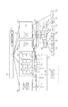
図1は本発明の実施例によるシステム構成を示す概略図であり、ネットワーク通信機能を備えた複合機(MFP)101とホストコンピュータ(以下、PC)102が、ネットワーク103等の伝送媒体で接続された環境を示す図である。
FIG. 1 is a schematic diagram showing a system configuration according to an embodiment of the present invention. A multifunction peripheral (MFP) 101 having a network communication function and a host computer (hereinafter referred to as PC) 102 are connected by a transmission medium such as a
また、点線104〜105は、処理/制御の流れを示すものとし、以下順に説明を行う。104は、ユーザがMFP101のスキャナより紙文書を読み込ませる処理を示す。その際、ユーザは、後述するMFP101のユーザーインターフェース(図2の203)より、送信する宛先(例えば、PC102)、各種送信設定(例えば、解像度、圧縮率)、データ書式(例えば、JPEG、TIFF、PDF、PDF高圧縮、PDF(OCR結果付き))を予め指定する。本実施例では、カラー画像の圧縮技術において本発明の領域判定方法を用いる例を説明するため、データ書式としてPDF高圧縮を指定した場合について説明を行う。PDF高圧縮の技術詳細については後述する。105は、指定された送信設定及びデータ書式に基づいて、MFP101の後述するソフトウェアあるいはハードウェア機能を利用してデータを生成し、指定された宛先に送信する処理を示す。ここで、PC102へ送信された画像は、PDFなどのファイルフォーマットで送信されることになるので、PC102の有する汎用的なビューアで閲覧可能である。
Dotted
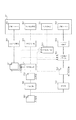
次に、図1におけるMFP101のハードウェアの詳細構成について図2を用いて説明する。
Next, a detailed hardware configuration of the
MFP101は、画像入力デバイスであるスキャナ部201、画像出力デバイスであるプリンタ部202、CPUやメモリ等で構成される制御ユニット(Controller Unit)204、ユーザーインターフェースである操作部203等を有する。制御ユニット204は、スキャナ部201、プリンタ部202、操作部203と接続し、一方では、LAN219や一般の電話回線網である公衆回線(WAN)220と接続することで、画像情報やデバイス情報の入出力を行うコントローラである。CPU205はシステム全体を制御するコントローラである。RAM206はCPU205が動作するためのシステムワークメモリであり、画像データを一時記憶するための画像メモリでもある。ROM210はブートROMであり、システムのブートプログラムが格納されている。HDD211はハードディスクドライブで、システム制御ソフトウェア、画像データを格納する。操作部I/F207は操作部(UI)203とのインターフェース部で、操作部203に表示するための画像データを操作部203に対して出力する。また、操作部203から本画像処理装置の使用者が入力した情報を、CPU205に伝える役割をする。ネットワーク(Network)208は本画像処理装置をLAN219に接続し、パケット形式の情報の入出力を行う。モデム(MODEM)209は本画像処理装置を公衆回線220に接続し、情報の復調・変調を行い入出力を行う。以上のデバイスがシステムバス221上に配置される。
The MFP 101 includes a
イメージバスインターフェース(Image Bus I/F)212はシステムバス221と画像データを高速で転送する画像バス222とを接続し、データ構造を変換するバスブリッジである。画像バス222は、例えば、PCIバスやIEEE1394で構成される。 An image bus interface (Image Bus I / F) 212 is a bus bridge that connects a system bus 221 and an image bus 222 that transfers image data at high speed, and converts a data structure. The image bus 222 is composed of, for example, a PCI bus or IEEE1394.
画像バス222上には以下のデバイスが配置される。ラスターイメージプロセッサ(RIP)213はPDLコードを解析し、ビットマップイメージに展開する。デバイスI/F部214は、信号線223を介して画像入出力デバイスであるスキャナ部201、信号線224を介してプリンタ部202、をそれぞれ制御ユニット204に接続し、画像データの同期系/非同期系の変換を行う。スキャナ画像処理部215は、入力画像データに対し補正、加工、編集を行う。プリンタ画像処理部216は、プリンタ部202に出力すべきプリント出力画像データに対して、プリンタ部202に応じた補正、解像度変換等を行う。画像回転部217は入力された画像データの回転を行い出力する。画像圧縮部218は、多値画像データに対してはJPEG圧縮伸長処理、または、デバイス固有の圧縮伸長処理を行い、2値画像画像データに対してはJBIG、MMR、MHの圧縮伸長処理を行う。以上が図1におけるMFP101のハードウェアの詳細構成である。
The following devices are arranged on the image bus 222. A raster image processor (RIP) 213 analyzes the PDL code and develops it into a bitmap image. The device I /
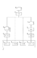
次に、図2における制御ユニット204に実装されるソフトウェア構成について図3を用いて説明する。301はユーザーインターフェース(以下、UI)であり、オペレータが操作部203を用いてMFPに対する各種操作・設定を行う際の、機器とユーザ操作との仲介を行うモジュールである。本モジュールは、オペレータの操作に従い、後述の各種モジュールに入力情報を転送して処理の依頼、或いはデータの設定等を行う。
Next, a software configuration installed in the control unit 204 in FIG. 2 will be described with reference to FIG. A user interface (hereinafter referred to as UI) 301 is a module that mediates between a device and a user operation when the operator performs various operations / settings on the MFP using the
302はアドレスブック(Address−Book)、即ちデータの送付先、通信先等を管理するデータベースモジュールである。アドレスブック302の内容は操作部203からの操作を、UI301で検知し、データの追加、削除、取得が行われ、オペレータの操作により後述の各モジュールにデータの送付・通信先情報を与えるものとして使用されるものである。
303はWebサーバモジュール(Web−Serverモジュール)であり、Webクライアント(例えば、PC102)からの要求により、本MFPの管理情報を通知するために使用される。この管理情報は、後述の統合送信部(Universal−Sendモジュール)304、後述のリモートコピースキャンモジュール(Remote−Copy−Scanモジュール)309、後述のリモートコピープリントモジュール(Remote−Copy−Printモジュール)310、後述の制御API(Control−API)318を介して読み取られ、後述のHTTPモジュール312、TCP/IP通信モジュール316、ネットワークドライバ(Network−Driver)317を介してWebクライアントに通知される。Webサーバモジュール303はWebクライアントに渡すべき情報を、HTML形式等のいわゆるWebページ(ホームページ)形式のデータとして作成する。必要に応じてJava(登録商標)やCGIプログラム等が用いられる。
304は統合送信部(Universal−Sendモジュール)、即ちデータの配信を司るモジュールであり、UI301を介してオペレータによって指定されたデータを、指示された通信(出力)先に配布するものである。また、オペレータにより、本MFPのスキャナ機能を使用して配布データの生成が指示された場合は、後述の制御API318を介して本MFPのスキャナ201を動作させ、データの生成を行う。
305は統合送信部304内で出力先にプリンタが指定された際に実行されるモジュールである。306は統合送信部304内で通信先にE−mailアドレスが指定された際に実行されるモジュールである。307は統合送信部304内で出力先にデータベースが指定された際に実行されるモジュールである。308は統合送信部304内で出力先に本MFPと同様のMFPが指定された際に実行されるモジュールである。
A module 305 is executed when a printer is designated as an output destination in the
309はリモートコピースキャン(Remote−Copy−Scan)モジュールであり、MFP101のスキャナ機能を使用してスキャナ201で読み取った画像情報の出力先をネットワーク等で接続された他のMFPのプリンタで出力し、本MFP101単体で実現しているコピー機能と同等の処理を行うモジュールである。310はリモートコピープリント(Remote−Copy−Print)モジュールであり、ネットワーク等で接続された他のMFPのスキャナで読み取った画像情報を入力元として得られた画像情報をMFP101のプリンタ機能を使用して出力することにより、同様にMFP101単体で実現しているコピー機能と同等の処理を行うモジュールである。ボックスモジュール311はスキャン画像もしくはPDLプリント画像をHDDに格納し、格納した画像のプリンタ機能による印刷、統合送信(Universal−Send)機能による送信、HDDに格納した文書の削除、グルーピング(個別BOXへの格納)、BOX間移動、BOX間コピーなどの管理機能を提供する。なお、ボックスモジュール311は、HTTPモジュール312及びTCP/IPモジュール316によって通信機能が提供される。
A remote copy scan (Remote-Copy-Scan) module 309 outputs the output destination of image information read by the
312はHTTPモジュールであり、本MFPがHTTPにより通信する際に使用され、後述のTCP/IP通信モジュール316により前述のWebサーバモジュール303、Webプルプリントモジュール311に通信機能を提供する。313はlprモジュールであり、後述のTCP/IP通信モジュール316により前述の統合送信部304内のプリンタモジュール305に通信機能を提供するものである。314はSMTPモジュールであり、後述のTCP/IP通信モジュール316により統合送信部304内のE−mailモジュール306に通信機能を提供する。315はSLM、即ちSalutation−Managerモジュールであり、後述のTCP/IP通信316モジュールにより前述の統合送信部304内のデータベースモジュール317、DPモジュール318、及びリモートコピースキャンモジュール309、リモートコピープリントモジュール310に通信機能を提供する。
316はTCP/IP通信モジュールであり、後述のネットワークドライバ316を用いて、前述の各種モジュールにネットワーク通信機能を提供する。317はネットワークドライバであり、ネットワークに物理的に接続される部分を制御するものである。
A TCP / IP communication module 316 provides a network communication function to the various modules described above using a network driver 316 described later.
318は制御APIであり、統合送信部304等の上流モジュールに対し、後述のジョブマネージャ(Job−Manager)319等の下流モジュールとのインターフェイスを提供するものであり、上流及び下流のモジュール間の依存関係を軽減し、それぞれの流用性を高めるものである。319はジョブマネージャであり、前述の各種モジュールより制御API318を介して指示される処理を解釈し、後述の各モジュール(320、324、326)に指示を与えるものである。また、ジョブマネージャ319は、FAXジョブの制御も含め本MFP内で実行される種々のジョブを一元管理するものである。
A control API 318 provides an interface with an upstream module such as the
320はコーデックマネージャ(CODEC−Manager)であり、ジョブマネージャ319が指示する処理の中でデータの各種圧縮・伸長を管理・制御するものである。321はFBEエンコーダモジュール(FBE−Encoder)であり、ジョブマネージャ319、後述のスキャンマネージャ(Scan−Manager)324により実行されるスキャン処理により読み込まれたデータをFBEフォーマットにより圧縮するものである。322はJPEGコーデックモジュール(JPEG−CODEC)であり、ジョブマネージャ319、スキャンマネージャ324により実行されるスキャン処理、及びプリントマネージャ(Print−Manager)326により実行される印刷処理において、読み込まれたデータのJPEG圧縮及び印刷データのJPEG展開処理を行うものである。323はMMRコーデック(MMR−CODEC)であり、ジョブマネージャ319、スキャンマネージャ324により実行されるスキャン処理、及びプリントマネージャ326により実行される印刷処理において、スキャナから読み込まれたデータのMMR圧縮及びプリンタへ出力すべき印刷データのMMR伸長処理を行うものである。
324はスキャンマネージャ(Scan−Manager)であり、ジョブマネージャ319が指示するスキャン処理を管理・制御するものである。325はSCSIドライバであり、スキャンマネージャ324と本MFPが内部的に接続しているスキャナ部201との通信を行うものである。326はプリントマネージャ(Print−Manager)であり、ジョブマネージャ319が指示する印刷処理を管理・制御するものである。327はエンジンインターフェース(Engine−I/F)であり、プリントマネージャ326とプリンタ部202とのI/Fを提供する。328はパラレルポートドライバであり、Webプルプリント311がパラレルポートを介して不図示の出力機器にデータを出力する際のI/Fを提供する。
次にAddress−Book302の詳細について説明する。このAddress−Book302は、MFP101内の不揮発性の記憶装置(不揮発性メモリやハードディスクなど)に保存されており、この中には、ネットワークに接続された他の機器の特徴が記載されている。例えば、以下に列挙するようなものが含まれている。
・機器の正式名やエイリアス名,
・機器のネットワークアドレス,
・機器の処理可能なネットワークプロトコル,
・機器の処理可能なドキュメントフォーマット,
・機器の処理可能な圧縮タイプ,
・機器の処理可能なイメージ解像度,
・プリンタ機器の場合の給紙可能な紙サイズや給紙段情報,
・サーバ(コンピュータ)機器の場合のドキュメントを格納可能なフォルダ名
以下に説明する各アプリケーションは、上記Address−Book302に記載された情報により配信先の特徴を判別することが可能となる。
Next, details of the Address-
・ The official name and alias name of the device,
・ Device network address,
・ Network protocol that can be processed by equipment,
-Document formats that can be processed by the device,
・ Compression type that can be processed by equipment,
・ Image resolution that can be processed by the device,
-Paper size and paper source information for printer devices,
-Folder name capable of storing documents in the case of server (computer) device Each application described below can determine the characteristics of the delivery destination based on the information described in the above Address-
このAddress−Book302を参照して、MFP101はデータを送信することができる。例えば、リモートコピーアプリケーションは、配信先に指定された機器の処理可能な解像度情報を前記Address−Book302より判別し、それに従い、スキャナにより読み込まれた画像2値画像を公知のMMR圧縮を用いて圧縮し、それを公知のTIFF(Tagged Image File Format)化し、SLM303に通して、ネットワーク上のプリンタ機器に送信する。SLM303については、詳細には説明しないが、公知のSalutation−Manager)と呼ばれる機器制御情報などを含んだネットワークプロトコルの一種である。
With reference to the Address-
次に、図1におけるホストコンピュータ102のハードウェア構成について図4を用いて説明する。ホストコンピュータ102ついては、一般的なパーソナルコンピュータの構成、機能を有しており、周辺機器であるモニタ401、キーボード・マウス402と、ホストコンピュータ102全体を制御する中央処理装置CPU403、アプリケーションやデータを記憶するハードディスク405、メモリ406等からなる。また、ネットワーク・インターフェース406を介してネットワーク103等の伝送媒体に接続されている。
Next, the hardware configuration of the host computer 102 in FIG. 1 will be described with reference to FIG. The host computer 102 has the configuration and functions of a general personal computer, and includes peripheral devices such as a
次に、前述したPDF高圧縮に関して、図5及び図6を用いて説明する。 Next, the above-described PDF high compression will be described with reference to FIGS.
ここでいうPDF高圧縮とは、カラー画像の圧縮技術であり、領域判定を行い、各領域の属性に応じて、MMRによる2値圧縮とJPEGによる非可逆圧縮とを適応的に変えて圧縮することにより、圧縮率を高くできるとともに、文字領域については高い品位が得られる圧縮方法である。 High-PDF compression here is a color image compression technique, which performs region determination and performs compression by adaptively changing between binary compression by MMR and irreversible compression by JPEG according to the attribute of each region. Thus, the compression rate can be increased and the character area can be obtained with high quality.
多値画像である入力画像(501)は、2値化部(502)で2値化され、2値画像(503)が生成される。領域判定部(504)は、2値画像(503)を入力とし、例えば、所定値の画素(例えば、黒画素)の輪郭線追跡等により画素塊を取得し、当該画素塊の大きさや位置に基づいてグループ化していくことにより領域を形成し、当該形成された領域内の画素塊の大きさや並び方などに基づいて文字領域を判別して、文字領域情報を生成する。文字領域情報は、文字領域の位置や大きさを示す情報である。また、領域判定部(504)が文字領域を判定することで、それ以外の部分は、写真やイラストや背景等の自然(階調)画像を示す写真領域として判定する。文字切り出し部(505)は、領域判定部(504)により、文字領域と判定した領域に対して、文字領域内における各文字(単位文字領域)を文字切り矩形として切り出し、文字切り矩形情報を生成する。文字切り矩形情報は、文字きり矩形の位置や大きさを示す情報である。文字領域情報、及び文字切り矩形情報は、文字領域情報(506)として情報管理されるものとする。また、2値画像(503)を入力とし、領域判定部(504)により文字領域と判定された領域について、文字領域毎の2値画像である部分2値画像(507)を生成する。 The input image (501), which is a multi-valued image, is binarized by the binarization unit (502), and a binary image (503) is generated. The region determination unit (504) receives the binary image (503) as an input, acquires a pixel block by, for example, contour tracking of a pixel (for example, a black pixel) of a predetermined value, and sets the size and position of the pixel block. A region is formed by grouping based on this, and a character region is determined based on the size and arrangement of pixel blocks in the formed region, thereby generating character region information. The character area information is information indicating the position and size of the character area. Further, the area determination unit (504) determines the character area, and the other part is determined as a photographic area indicating a natural (gradation) image such as a photograph, an illustration, or a background. The character cutout unit (505) cuts out each character (unit character region) in the character region as a character cut rectangle for the region determined by the region determination unit (504) as the character region, and generates character cut rectangle information To do. The character cut rectangle information is information indicating the position and size of the character cut rectangle. It is assumed that the character area information and the character cut rectangle information are managed as character area information (506). Also, a binary image (503) is input, and a partial binary image (507), which is a binary image for each character area, is generated for the area determined as a character area by the area determination unit (504).
一方で、入力画像(501)は、縮小部(512)により縮小(又は低解像度化)され、縮小多値画像(513)が生成される。代表色抽出部(510)は、部分2値画像(507)を入力とし、文字領域情報(506)及び縮小多値画像(513)を参照しながら、文字切り矩形の代表色を算出し、その結果を文字色情報(511)として情報管理する(尚、この処理の詳細については、特許文献2参照)。文字領域穴埋め部(514)は、縮小多値画像(513)を入力とし、文字領域情報(506)及び部分2値画像(507)を参照しながら、縮小多値画像(513)の各文字領域あるいは文字切り矩形を、その周辺色で塗り潰す処理を行う(尚、この処理の詳細については、特許文献1参照)。
On the other hand, the input image (501) is reduced (or reduced in resolution) by the reduction unit (512), and a reduced multi-valued image (513) is generated. The representative color extraction unit (510) receives the partial binary image (507) as input, calculates the representative color of the character cut rectangle while referring to the character region information (506) and the reduced multi-value image (513), The result is managed as character color information (511) (refer to
以上の処理の後、部分2値画像(507)は各々、MMR圧縮部(508)により圧縮コード1(509)として圧縮される。また、文字領域穴埋め部(514)にて穴埋めされた穴埋め多値画像は、JPEG圧縮部(515)により圧縮コード2(516)として圧縮される。 After the above processing, each partial binary image (507) is compressed as a compressed code 1 (509) by the MMR compression unit (508). In addition, the multi-valued image filled in with the character region filling unit (514) is compressed as compressed code 2 (516) by the JPEG compression unit (515).
このようにして、各構成要素から得られる文字領域情報(506)、圧縮コード1(509)、文字色情報(511)、圧縮コード2(516)のデータ群を結合した圧縮データ(517)が生成される。この圧縮データ(517)を、更に、PDFなどで可逆圧縮することにより、PDF高圧縮データが生成される。 Thus, the compressed data (517) obtained by combining the data groups of the character area information (506), the compressed code 1 (509), the character color information (511), and the compressed code 2 (516) obtained from each component is obtained. Generated. The compressed data (517) is further reversibly compressed with PDF or the like to generate PDF highly compressed data.
図6は、前述したように生成された圧縮データ(517)を伸長する概略構成を示す図である。MMR伸長部(601)は圧縮コード1(509)を入力とし、MMR伸長処理を行い、部分2値画像(602)を生成する。JPEG伸長部(605)は圧縮コード2(516)を入力し、JPEG伸長処理を行い、さらに拡大部(606)で拡大処理を行うことで、多値画像(607)を生成する。合成部(603)は文字領域情報(506)を参照しながら、文字色情報(511)を部分2値画像(602)の黒画素に割り当て、その文字色が割り当てられた部分2値画像を多値画像(607)の上に合成して表示する。この際、部分2値画像(602)の白画素は透明色が割り当てられており、多値画像(607)を透過する。 FIG. 6 is a diagram showing a schematic configuration for expanding the compressed data (517) generated as described above. The MMR decompression unit (601) receives the compression code 1 (509) as input, performs MMR decompression processing, and generates a partial binary image (602). The JPEG decompression unit (605) receives the compression code 2 (516), performs JPEG decompression processing, and further performs enlargement processing in the enlargement unit (606), thereby generating a multi-value image (607). The synthesizing unit (603) assigns the character color information (511) to the black pixels of the partial binary image (602) while referring to the character area information (506), and selects the partial binary image to which the character color is assigned. It is synthesized and displayed on the value image (607). At this time, the white pixels of the partial binary image (602) are assigned a transparent color and pass through the multi-valued image (607).
このように、画像伸長装置は、画像圧縮装置により生成された圧縮データを伸長し、画像を復元する。 As described above, the image decompression device decompresses the compressed data generated by the image compression device and restores the image.
図7は、図5及び図6で使用、または生成される画像の概略図を示す。 FIG. 7 shows a schematic diagram of the images used or generated in FIGS. 5 and 6.
701は、入力画像(501)を示す。702は、2値画像(503)を示す。
703は、領域判定部(504)により、文字領域、写真領域に領域判定された結果を示す。ここで、704及び706は文字領域と判定され、705は写真領域として判定されたものとする。
707、708は、領域判定部(504)により文字領域と判定された領域の部分2値画像(507)を示す。
709は、文字切り出し部(505)により切り出された文字切り矩形の概略図を示す。710は、文字領域704の文字切り矩形であり、711、712は、文字領域706の文字切り矩形である。ここで、711、712に示すように文字領域内の文字切り矩形の中に、文字と写真が混在することがある。例えば、特許文献1のように画素の集まりを位置の近さやサイズの一致に基づいてグループ化した場合、文字サイズに近い写真領域が文字領域内に混在する場合がある。これらの矩形全てを文字として扱うと、712のような本来写真として扱うべき矩形は、2値画像として処理が行われるため、情報の欠落が生じる。仮に文字領域内の文字切り矩形を全て文字として扱った場合に生成される圧縮データ(517)または、PDF高圧縮データを713に示す。ここで、714に示すように本来階調や色を有する写真領域が文字領域として扱われて2値化されてしまい、情報欠落が生じることになる。
Reference numeral 709 denotes a schematic diagram of a character cut rectangle cut out by the character cutout unit (505).
これらの問題点を解決するために、本発明では、図8に示すように領域判定部2(801)を更に設け、文字切り矩形の領域判定を行う。その他の構成要素は図5と同様である。 In order to solve these problems, in the present invention, an area determination unit 2 (801) is further provided as shown in FIG. Other components are the same as those in FIG.
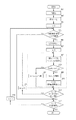
次に、図9のフローチャートを用いて、本発明のポイントである領域判定部2(801)の説明を行う。ここで、図9のフローチャートは、図8の処理の一部であるため、図8を適宜参照する。また、領域判定部2(801)は、図9の907〜910の処理を示す。 Next, the area determination unit 2 (801), which is the point of the present invention, will be described using the flowchart of FIG. Here, the flowchart of FIG. 9 is a part of the processing of FIG. 8, and therefore FIG. 8 is referred to as appropriate. The area determination unit 2 (801) shows the processing from 907 to 910 in FIG.
まず、ステップ901にて、入力画像(501)に対して2値化部(502)により2値化を行う。
First, in
次に、ステップ902にて、2値画像(503)に対して領域判定部(504)により領域判定を行う。ステップ902での領域判定は、例えば、2値画像において輪郭線追跡を行うことによって画素塊を取得し、近くの画素塊同士をグループ化することにより分割されてしまっている文字や文字行が結合されることになる。このグループ化によって形成された領域に含まれる画素塊の大きさや位置関係などに基づいて、当該領域が1又は複数の文字を含む文字領域かどうかの判定が行われる。
Next, in
次に、ステップ903にて、領域数のカウンタであるnを初期化する。次に、ステップ904にて、注目領域が文字領域と判定された領域である場合は、ステップ905へ、非文字領域と判定された領域である場合は、ステップ912へ進む。
In
ステップ905では、文字切り出し部(505)にて文字切り出しを行う。例えば、水平方向にヒストグラムを取って文字行を切り出し、各文字行の垂直方向のヒストグラムを取って文字矩形を切り出すことができる。
In
ステップ906にて、文字切り矩形数のカウンタであるmを初期化する。次に、領域判定部2(801)において、まず、ステップ907にて、文字切り矩形内の閉ループ数(NumLoop)を算出する。閉ループ数とは、文字切り矩形内における黒画素、または白画素の輪郭数であり、詳細については、後述する。次に、ステップ908にて、閉ループ数(NumLoop)と予め設定された閾値th(例えば閾値th=9)を比較する(ここで、閾値thは、固定値でもよいが、文字切り矩形の大きさに応じて動的に可変としてもよい)。閾値よりも小さい場合は、ステップ909にてTEXTと判断され、閾値以上の場合は、ステップ910にてIMAGEと判断される。
In
ステップ911にて、文字切り矩形数のカウンタmと文字領域内の文字切り矩形数Mとの比較を行い、全ての文字切り矩形についてステップ907〜910の処理が終了している(m==M−1)と判断するとステップ912へ進む。一方、未処理の文字切り矩形があると判断した場合は、ステップ913にてカウンタmを増やしてステップ907に戻る。
In
ステップ912にて、領域数のカウンタnと領域数Nの比較を行い、全ての領域についての判定が終了したと判断すると本処理を終了し、未処理の領域があると判断した場合は、ステップ914にてカウンタnを増やしてステップ904に戻る。
In
このように、領域判定部2(801)では、文字領域内に含まれる各文字切り矩形がTEXTであるかIMAGEであるかの判定を、閉ループ数に基づいて行う。ここで、入力画像(501)を701とした場合、領域判定部2(801)で各文字切り矩形の判定を行った結果を図10の1001に示す。また、図8の802は、この結果にもとづいて、領域が文字領域かつ領域判定部2(801)でTEXTと判定された文字切り矩形領域を用いて部分2値画像を生成することを示しており、この生成された部分2値画像の概略図を図10の1002に示す。領域判定部2での判定処理が無い場合は図7の714のように写真領域が2値化されてしまっていたが、領域判定部2での判定処理を行った場合に生成される圧縮データ(517)は、高精度に領域判定できるので、図10の1003のように写真領域が2値化されてしまわずに済む。
As described above, the area determination unit 2 (801) determines whether each character cut rectangle included in the character area is TEXT or IMAGE based on the number of closed loops. Here, when the input image (501) is 701, the result of determining each character-cut rectangle by the area determination unit 2 (801) is shown in 1001 of FIG. Further, reference numeral 802 in FIG. 8 indicates that, based on this result, a partial binary image is generated using a character-cut rectangular area in which the area is a character area and the area determination unit 2 (801) determines TEXT. A schematic diagram of the generated partial binary image is shown at 1002 in FIG. When there is no determination process in the
次に、ステップ907の閉ループ数の算出方法について図11を用いて説明する。2値画像からの輪郭線の抽出は、まず2値画像における輪郭線追跡のため追跡開始点を見つけることから始められる。そして、この追跡開始点が発見されると、次にこの追跡開始点から順にその画像の輪郭を追跡していき、追跡の終わった輪郭点には次々に追跡済のマークを付けながら追跡を続行する。こうして、この追跡が一巡した時点で一つの輪郭点列(輪郭線)を求めている。このような手順を繰り返し行なうことにより、その画像中のすべての輪郭線を抽出することができる。文字切り矩形内におけるこれらの輪郭線の総数を本実施形態では、閉ループ数(NumLoop)としている。
Next, a method for calculating the number of closed loops in
図11は、文字切り矩形の一例であり、まず、ラスタスキャンを行って白画素から黒画素に変化する点を輪郭線追跡のため追跡開始点1101として発見する。次に、破線矢印1102に沿って輪郭を追跡する。1102が追跡開始点1101に戻ると閉ループ数は、1つカウントされる。そして、次の追跡開始点1103が発見され、以下、同様の処理が行われる。図11では、閉ループ数は2とカウントされる。
FIG. 11 shows an example of a character cut rectangle. First, a raster scan is performed to find a point that changes from a white pixel to a black pixel as a tracking
また、図12の1205〜1209はそれぞれ、文字切り矩形の例であり、夫々の閉ループ数(NumLoop)を示している。ここで、1205〜1208のような文字の場合は、閉ループ数が1桁と少ないが、1209のような写真の場合は、閉ループ数が極端に多いという特徴がある。
In addition,
以上のように、領域判定部2(801)において、文字切り矩形の閉ループ数にもとづいて、文字切り矩形が文字か写真かを判定することで、高精度に領域判定を行うことができるようになる。高精度に領域判定できるようになるので、良好な画質の圧縮データ(517)またはPDF高圧縮データを得ることが可能となる。 As described above, the region determination unit 2 (801) can determine the region with high accuracy by determining whether the character cut rectangle is a character or a photo based on the number of closed loops of the character cut rectangle. Become. Since the region can be determined with high accuracy, it is possible to obtain compressed data (517) or PDF high-compressed data with good image quality.
(実施例2)
実施例1では、文字切り矩形の閉ループ数にもとづいて、文字切り矩形が文字か写真かを判定する場合について説明した。しかし、例えば、複雑な漢字は、アルファベット、ひらがなを含む一般的な文字に対して、閉ループ数が比較的多くなる傾向があり、また、逆に、複雑な漢字の閉ループ数程度に少ない閉ループ数をもつ写真も存在する。
(Example 2)
In the first embodiment, the case where it is determined whether the character cut rectangle is a character or a photograph based on the number of closed loops of the character cut rectangle has been described. However, for example, complex kanji characters tend to have a relatively large number of closed loops compared to general characters including alphabets and hiragana characters. There are also photos with it.
実施例1では閉ループ数の閾値thを1つ用いて判断することにしていたが、実施例2では、閉ループ数の閾値を複数段階に分け、閉ループ数以外の特徴量を利用できるようにすることにより、文字切り矩形の判定をより良好に行うための領域判定方法について説明する。尚、実施例1と同様の処理部分に関しては、基本的に、同図面、同図番を使用することとし、説明を省略する。 In the first embodiment, the determination is made using one threshold th for the number of closed loops, but in the second embodiment, the threshold value for the number of closed loops is divided into a plurality of stages so that features other than the number of closed loops can be used. Thus, an area determination method for better determining a character cut rectangle will be described. Note that the same processing portions as those in the first embodiment are basically used in the same drawing and the same drawing number, and the description thereof is omitted.
以下、閉ループ数の閾値を複数設けた場合の領域判定方法について、図13のフローチャートを用いて説明する。 Hereinafter, a region determination method in the case where a plurality of threshold values for the number of closed loops are provided will be described with reference to the flowchart of FIG.
図13は、実施例1で使用した図9の907〜910に対応する領域判定部2(801)である。まず、ステップ1301にて、実施例1で前述したように閉ループ数を算出する。次に、ステップ1302にて、閉ループ数(NumLoop)と予め設定された第1の閾値th1を比較する。ここで、閾値th1よりも小さい場合は、ステップ1303進み、閾値th1以上の場合は、ステップ1307にてIMAGEと判断される。ステップ1303では、閉ループ数(NumLoop)と予め設定された第2の閾値th2と比較する。ここで、閾値th2よりも小さい場合は、ステップ1306にて、TEXTと判断される。閾値th2以上の場合は、ステップ1304にて色分散値(ColorStd)を算出する。色分散値の算出方法については、後述する。次に、ステップ1305にて、色分散値と予め設定された色分散値の閾値th3を比較する。ここで、閾値th3よりも小さい場合は、ステップ1306にて、TEXTと判断される。閾値th3以上の場合は、ステップ1307にてIMAGEと判断される。なお、各閾値は実験的に求めた値を用いればよく、例えば、th1=18、th2=6というような値などが用いてもよい。
FIG. 13 shows an area determination unit 2 (801) corresponding to 907 to 910 in FIG. 9 used in the first embodiment. First, in
ここで、前述したように閉ループ数が比較的多くなる複雑な漢字や閉ループ数が比較的少ない写真を第2の閾値th2より大きくなるように第2の閾値th2を設定し、一般的な単色(例えば、黒)の文字に対して、一般的な多階調表現をもつ写真は、色分散値が大きくなるという特徴を利用することで、ステップ1305にてそれらを良好に判定することが可能となる。
Here, as described above, the second threshold th2 is set so that a complicated Chinese character having a relatively large number of closed loops or a photograph having a relatively small number of closed loops is larger than the second threshold th2. For example, a photograph having a general multi-gradation expression for black characters can be determined well in
次に、色分散値の算出方法について説明する。ここで、色情報は、縮小多値画像(513)の色(例RGB値の各8bit)を参照する必要がある。さらに、好ましくは、RGB値を輝度、色差情報に変換した値(例えば、YCbCr値の各8bit)を参照する。ここでは、例としてYCbCr値のCb値の色分散値を算出する。RGBからYCbCrへの変換方法については、公知であるため、説明を省略する。 Next, a method for calculating the chromatic dispersion value will be described. Here, the color information needs to refer to the color of the reduced multi-valued image (513) (e.g., 8 bits for each of the RGB values). Further, preferably, a value obtained by converting the RGB value into luminance and color difference information (for example, 8 bits for each YCbCr value) is referred to. Here, as an example, the chromatic dispersion value of the Cb value of the YCbCr value is calculated. Since the conversion method from RGB to YCbCr is well-known, description is abbreviate | omitted.
色分散値は、一般的に知られるvarianceを用い、下記の式で求められる。 The chromatic dispersion value is obtained by the following equation using a generally known variation.
variance(分散):Σ(Cb(i)−m)2/n
(n:データ数(文字切り矩形内の黒画素数)、
Cb(i):文字切り矩形内の黒画素と位置的に対応する縮小多値画像のCb値、
m(平均):ΣCb(i)/n)
以上のように、閉ループ数の閾値を段階的に分け、各々の段階に応じて閉ループ数以外の特徴量を併用することで、より良好な領域判定が可能となる。
variance (dispersion): Σ (Cb (i) −m) 2 / n
(N: number of data (number of black pixels in the character cut rectangle),
Cb (i): Cb value of the reduced multi-valued image corresponding to the black pixel in the character cut rectangle,
m (average): ΣCb (i) / n)
As described above, the threshold value for the number of closed loops is divided in stages, and a feature amount other than the number of closed loops is used in combination according to each stage, so that better region determination can be performed.
尚、実施例2では、閉ループ数とは異なる別の特徴量として色分散値を利用して説明を行ったが、これに限るものではなく、例えば、文字切り矩形内に占める黒画素の密度情報、または孤立画素情報などを利用してもよい。 In the second embodiment, the chromatic dispersion value is used as another feature amount different from the number of closed loops. However, the present invention is not limited to this. For example, the density information of black pixels occupying a character cut rectangle Alternatively, isolated pixel information or the like may be used.
(実施例3)
実施例1では、カラー複写機に搭載可能な、カラー画像の圧縮技術において本領域判定方法を用いる例について説明したが、これに限るものではなく、本発明は、モノクロ複写機におけるモノクロ画像の圧縮技術、あるいは、カラー複写機におけるモノクロ画像の圧縮技術においても利用可能である。モノクロ画像の圧縮技術の場合は、図5の入力画像(501)は、例えばグレースケール(8bit)であり、2値画像(503)及び縮小多値画像(513)をMMRによる2値圧縮とJPEGによる非可逆圧縮との組み合わせで実現する。
(Example 3)
In the first embodiment, an example in which the present area determination method is used in a color image compression technique that can be mounted on a color copying machine has been described. However, the present invention is not limited to this, and the present invention can compress a monochrome image in a monochrome copying machine. The present invention can also be used in a technology or a monochrome image compression technology in a color copying machine. In the case of a monochrome image compression technique, the input image (501) in FIG. 5 is, for example, gray scale (8 bits), and the binary image (503) and the reduced multi-value image (513) are subjected to binary compression by MMR and JPEG. Realized in combination with lossy compression by.
(実施例4)
実施例1〜3では、画像の圧縮技術において本領域判定方法を用いる例を説明した。実施例4では、光学的文字認識(OCR)技術を用いる際に、本領域判定方法を用いる例を説明する。
Example 4
In the first to third embodiments, the example in which the region determination method is used in the image compression technique has been described. In the fourth embodiment, an example in which this region determination method is used when an optical character recognition (OCR) technique is used will be described.
前述したように、OCR処理では、文書画像に対して濃度射影(ヒストグラム)を取ることにより文字行を切り出し(抽出)、さらに1文字単位の文字ブロック切り出し(抽出)を行う。そして、個々の文字ブロックから特徴データを抽出して、標準パタンとの類似度が計算され、最も類似度の高い文字を認識結果として出力する。即ち、文字ブロック切り出し(抽出)処理までは、実施例1の図9で前述したように、2値化、領域判定、文字切り出しを行うことを意味する。また、前述したように、文字切り矩形が非文字である場合、非文字に対して文字認識を行ってしまうと、全体の処理速度を低下させてしまう他、意味のないテキストコードを出力してしまう場合もあり好ましくない。 As described above, in the OCR process, a character line is cut out (extracted) by taking a density projection (histogram) on the document image, and further, a character block cut out (extracted) in units of one character. Then, feature data is extracted from each character block, the similarity with the standard pattern is calculated, and the character with the highest similarity is output as the recognition result. That is, up to the character block cutout (extraction) process means binarization, area determination, and character cutout as described above with reference to FIG. In addition, as described above, when the character cut rectangle is non-character, if character recognition is performed on the non-character, the overall processing speed is reduced, and a meaningless text code is output. This is not preferable.
ここで、実施例4では、OCR処理を行う前に、図8の領域判定部2で、予め文字切り矩形の領域判定を行うことで、文字か非文字かを判定しておき、文字と判定された場合のみOCR処理を行うことでこれらの問題を解決する。この処理を図14のフローチャートに示す。図14において、901〜914の処理部分は、実施例1で前述した図9と同様であるため、説明を省略する。ステップ908にて、閉ループ数(NumLoop)と予め設定された閾値thを比較し、閾値よりも小さい場合は、ステップ909にてTEXTと判断されるため、ステップ1401にてOCR処理を行い、文字認識結果を出力する。また、閾値以上の場合は、ステップ910にてIMAGEと判断されるため、OCR処理は行わない。
Here, in the fourth embodiment, before performing the OCR processing, the
以上のように、OCR技術を用いる際、不要なOCR処理を行わないため、処理速度の向上が図られ、また、意味のないテキストコードを出力してしまうことを抑えることが可能となる。 As described above, when the OCR technique is used, unnecessary OCR processing is not performed, so that the processing speed is improved, and it is possible to suppress the output of meaningless text codes.
(実施例5)
実施例1では、図8のように、領域判定部(504)で複数の文字を含む文字領域を判定し、その領域から文字切りだし部(505)で文字矩形領域を切り出して、領域判定部2(801)において、閉ループの数に基づいて文字か否か判断していたが、この処理の流れに限るものではない。例えば、領域判定部(504)で文字領域の判定を行わずに、文字切りだし部(505)において、画像503から直接文字矩形領域を切り出すことができるようにし、領域判定部2(801)において、該文字矩形領域の閉ループの数に基づいて文字か否か判断するようにしてもよい。
(Example 5)
In the first embodiment, as shown in FIG. 8, the area determination unit (504) determines a character area including a plurality of characters, and the character cutout part (505) cuts out a character rectangular area from the area. In 2 (801), whether or not the character is a character is determined based on the number of closed loops, but is not limited to this processing flow. For example, without determining the character area by the area determination unit (504), the character extraction unit (505) can directly extract the character rectangular area from the
(実施例6)
本発明は、複数の機器(例えばホストコンピュータ、インタフェース機器、リーダ、プリンタなど)から構成されるシステムに適用しても、一つの機器からなる装置(例えば、複写機、ファクシミリ装置など)に適用してもよい。
(Example 6)
The present invention can be applied to a system composed of a plurality of devices (for example, a host computer, an interface device, a reader, a printer, etc.) or an apparatus composed of a single device (for example, a copier, a facsimile machine, etc.). May be.
また、本発明の目的は、前述した実施形態の機能を実現するソフトウェアのプログラムコードを記録した記録媒体を、システムあるいは装置に供給し、そのシステムあるいは装置のコンピュータ(またはCPUやMPU)が記録媒体に格納されたプログラムコードを読み出し実行することによっても、達成されることは言うまでもない。この場合、記録媒体から読み出されたプログラムコード自体が本発明の新規な機能を実現することになり、そのプログラムコードを記憶した記憶媒体は本発明を構成することになる。プログラムコードを供給するための記憶媒体としては、例えば、フロッピー(登録商標)ディスク、ハードディスク、光ディスク、光磁気ディスク、CD−ROM、CD−R、磁気テープ、不揮発性のメモリカード、ROMなどを用いることができる。 Another object of the present invention is to supply a recording medium recording a program code of software that implements the functions of the above-described embodiments to a system or apparatus, and the computer (or CPU or MPU) of the system or apparatus records the recording medium. Needless to say, this can also be achieved by reading and executing the program code stored in. In this case, the program code itself read from the recording medium realizes the novel function of the present invention, and the storage medium storing the program code constitutes the present invention. As a storage medium for supplying the program code, for example, a floppy (registered trademark) disk, hard disk, optical disk, magneto-optical disk, CD-ROM, CD-R, magnetic tape, nonvolatile memory card, ROM, or the like is used. be able to.
また、コンピュータが読み出したプログラムコードを実行することにより、前述した実施形態の機能が実現されるだけでなく、そのプログラムコードの指示に基づき、コンピュータ上で稼動しているOSなどが実際の処理の一部または全部を行い、その処理によって前述した実施形態の機能が実現される場合も含まれることは言うまでもない。 Further, by executing the program code read by the computer, not only the functions of the above-described embodiments are realized, but also the OS running on the computer based on the instruction of the program code performs the actual processing. Needless to say, a case where the function of the above-described embodiment is realized by performing part or all of the processing is also included.
さらに、記録媒体から読み出されたプログラムコードが、コンピュータに挿入された拡張機能ボードやコンピュータに接続された機能拡張ユニットに備わるメモリに書き込まれた後、そのプログラムコードに指示に基づき、その機能拡張ボードや機能拡張ユニットに備わるCPUなどが実際の処理の一部または全部を行い、その処理によって前述した実施形態の機能が実現される場合も含まれることは言うまでもない。 Further, after the program code read from the recording medium is written in the memory provided in the extension function board inserted in the computer or the function extension unit connected to the computer, the function extension is performed based on the instruction in the program code. It goes without saying that the CPU or the like provided in the board or the function expansion unit performs part or all of the actual processing, and the functions of the above-described embodiments are realized by the processing.
以上のように、本発明によれば、領域判定精度を向上させることが可能となる。また文字と非文字の好適な領域判定を実行することができるので、良好な画質が得られると共に、圧縮効率を向上させることが可能となる。また、OCR技術を用いる際、処理速度の向上と共に、意味のないテキストコードを出力してしまうことを抑え、認識率を向上させることが可能となる。 As described above, according to the present invention, it is possible to improve the region determination accuracy. In addition, since it is possible to execute suitable region determination for characters and non-characters, it is possible to obtain good image quality and improve compression efficiency. Further, when using the OCR technology, it is possible to improve the recognition rate by suppressing the output of meaningless text codes as well as the processing speed.
Claims (13)
前記領域抽出手段で抽出された判定対象領域内の閉ループ数を算出する閉ループ数算出手段と、
前記判定対象領域から前記閉ループ数と異なる特徴量を抽出する特徴量抽出手段と、
前記閉ループ数算出手段により算出された閉ループ数が第1の閾値より小さい場合、当該判定対象領域を文字領域と判定し、
前記閉ループ数算出手段により算出された閉ループ数が第2の閾値(ここで第2の閾値>第1の閾値とする)より大きい場合、当該判定対象領域を写真領域と判断し、
前記閉ループ数算出手段により算出された閉ループ数が前記第1の閾値以上で且つ前記第2の閾値以下である場合、前記特徴量抽出手段で抽出された特徴量に基づいて当該判定対象領域が文字領域か否かを判定する領域判定手段と、
を備えることを特徴とする画像処理装置。 Area extracting means for extracting a determination target area from a document image;
Closed loop number calculating means for calculating the number of closed loops in the determination target area extracted by the area extracting means;
Feature amount extraction means for extracting a feature amount different from the number of closed loops from the determination target region;
When the closed loop number calculated by the closed loop number calculating means is smaller than the first threshold, the determination target area is determined as a character area;
If the number of closed loops calculated by the closed loop number calculating means is larger than a second threshold value (where second threshold value> first threshold value), the determination target region is determined as a photo region,
When the number of closed loops calculated by the closed loop number calculating means is not less than the first threshold and not more than the second threshold, the determination target region is a character based on the feature quantity extracted by the feature quantity extracting means. Area determination means for determining whether or not the area;
An image processing apparatus comprising:
前記領域抽出手段では、前記プレ判定手段で判定された文字領域候補に含まれる文字矩形を、前記判定対象領域として抽出することを特徴とする請求項1に記載の画像処理装置。 A pre-determination unit that determines a character region candidate from the image based on a pixel block included in the document image;
The image processing apparatus according to claim 1, wherein the region extraction unit extracts a character rectangle included in the character region candidate determined by the pre-determination unit as the determination target region.
前記領域抽出手段での抽出対象となる文書画像は、前記2値化手段により生成された2値画像であることを特徴とする請求項1または2に記載の画像処理装置。 An image processing apparatus further comprising binarization means for generating a binary image from a multivalued image,
The image processing apparatus according to claim 1, wherein the document image to be extracted by the region extraction unit is a binary image generated by the binarization unit.
前記圧縮データには、前記第1の圧縮処理により得られる第1圧縮コードと、前記第2の圧縮処理により得られる第2圧縮コードと、前記代表色算出手段で得られる代表色の情報とが含まれることを特徴とする請求項6に記載の画像処理装置。 An image processing apparatus further comprising representative color calculation means for calculating a representative color from an area determined as a character area by the area determination means,
The compressed data includes a first compressed code obtained by the first compression process, a second compressed code obtained by the second compression process, and representative color information obtained by the representative color calculation means. The image processing apparatus according to claim 6 , wherein the image processing apparatus is included.
閉ループ数算出手段が、前記領域抽出ステップで抽出された判定対象領域内の閉ループ数を算出する閉ループ数算出ステップと、
特徴量抽出手段が、前記判定対象領域から前記閉ループ数と異なる特徴量を抽出する特徴量抽出ステップと、
領域判定手段が、前記閉ループ数算出ステップで算出された閉ループ数が第1の閾値より小さい場合、当該判定対象領域を文字領域と判定し、
前記閉ループ数算出ステップで算出された閉ループ数が第2の閾値(ここで第2の閾値>第1の閾値とする)より大きい場合、当該判定対象領域を写真領域と判断し、
前記閉ループ数算出ステップで算出された閉ループ数が前記第1の閾値以上で且つ前記第2の閾値以下である場合、前記特徴量抽出ステップで抽出された特徴量に基づいて当該判定対象領域が文字領域か否かを判定する領域判定ステップと、
を備えることを特徴とする、画像処理装置による画像処理方法。 An area extracting step in which the area extracting means extracts a determination target area from the document image;
A closed loop number calculating means for calculating a closed loop number in the determination target region extracted in the region extracting step;
A feature amount extraction unit for extracting a feature amount different from the number of closed loops from the determination target region;
When the closed loop number calculated in the closed loop number calculating step is smaller than the first threshold , the area determination unit determines that the determination target area is a character area,
If the number of closed loops calculated in the closed loop number calculating step is greater than a second threshold value (where second threshold value> first threshold value), the determination target region is determined as a photographic region;
When the number of closed loops calculated in the closed loop number calculating step is not less than the first threshold and not more than the second threshold, the determination target region is a character based on the feature amount extracted in the feature amount extraction step. An area determination step for determining whether or not the area;
An image processing method using an image processing apparatus.
文書画像から判定対象領域を抽出する領域抽出手段、
前記領域抽出手段で抽出された判定対象領域内の閉ループ数を算出する閉ループ数算出手段、
前記判定対象領域から前記閉ループ数と異なる特徴量を抽出する特徴量抽出手段、
前記閉ループ数算出手段により算出された閉ループ数が第1の閾値より小さい場合、当該判定対象領域を文字領域と判定し、
前記閉ループ数算出手段により算出された閉ループ数が第2の閾値(ここで第2の閾値>第1の閾値とする)より大きい場合、当該判定対象領域を写真領域と判断し、
前記閉ループ数算出手段により算出された閉ループ数が前記第1の閾値以上で且つ前記第2の閾値以下である場合、前記特徴量抽出手段で抽出された特徴量に基づいて当該判定対象領域が文字領域か否かを判定する領域判定手段、
として機能させるためのコンピュータプログラム。 Computer
Area extraction means for extracting a determination target area from a document image;
Closed loop number calculating means for calculating the number of closed loops in the determination target area extracted by the area extracting means;
Feature amount extraction means for extracting a feature amount different from the number of closed loops from the determination target region;
When the closed loop number calculated by the closed loop number calculating means is smaller than the first threshold, the determination target area is determined as a character area;
If the number of closed loops calculated by the closed loop number calculating means is larger than a second threshold value (where second threshold value> first threshold value), the determination target region is determined as a photo region,
When the number of closed loops calculated by the closed loop number calculating means is not less than the first threshold and not more than the second threshold, the determination target region is a character based on the feature quantity extracted by the feature quantity extracting means. Area determination means for determining whether or not the area;
Computer program to function as.
Priority Applications (2)
| Application Number | Priority Date | Filing Date | Title |
|---|---|---|---|
| JP2005124984A JP4579759B2 (en) | 2005-04-22 | 2005-04-22 | Image processing apparatus, image processing method, and computer program |
| US11/379,225 US7848572B2 (en) | 2005-04-22 | 2006-04-19 | Image processing apparatus, image processing method, computer program |
Applications Claiming Priority (1)
| Application Number | Priority Date | Filing Date | Title |
|---|---|---|---|
| JP2005124984A JP4579759B2 (en) | 2005-04-22 | 2005-04-22 | Image processing apparatus, image processing method, and computer program |
Publications (3)
| Publication Number | Publication Date |
|---|---|
| JP2006304062A JP2006304062A (en) | 2006-11-02 |
| JP2006304062A5 JP2006304062A5 (en) | 2008-05-29 |
| JP4579759B2 true JP4579759B2 (en) | 2010-11-10 |
Family
ID=37186964
Family Applications (1)
| Application Number | Title | Priority Date | Filing Date |
|---|---|---|---|
| JP2005124984A Expired - Fee Related JP4579759B2 (en) | 2005-04-22 | 2005-04-22 | Image processing apparatus, image processing method, and computer program |
Country Status (2)
| Country | Link |
|---|---|
| US (1) | US7848572B2 (en) |
| JP (1) | JP4579759B2 (en) |
Cited By (1)
| Publication number | Priority date | Publication date | Assignee | Title |
|---|---|---|---|---|
| KR102579826B1 (en) * | 2022-12-09 | 2023-09-18 | (주) 브이픽스메디칼 | Method, apparatus and system for providing medical diagnosis assistance information based on artificial intelligence |
Families Citing this family (7)
| Publication number | Priority date | Publication date | Assignee | Title |
|---|---|---|---|---|
| JP5103074B2 (en) * | 2007-07-06 | 2012-12-19 | 京セラドキュメントソリューションズ株式会社 | Image processing apparatus and image forming apparatus |
| US8270717B2 (en) * | 2007-12-19 | 2012-09-18 | Canon Kabushiki Kaisha | Metadata determination method and image forming apparatus |
| JP4952627B2 (en) * | 2008-03-21 | 2012-06-13 | 富士通株式会社 | Image processing apparatus, image processing method, and image processing program |
| WO2011111446A1 (en) * | 2010-03-08 | 2011-09-15 | コニカミノルタホールディングス株式会社 | Image forming system, controller and rasterization accelerator |
| JP5776419B2 (en) * | 2011-07-29 | 2015-09-09 | ブラザー工業株式会社 | Image processing device, image processing program |
| JP5853495B2 (en) * | 2011-08-26 | 2016-02-09 | 富士ゼロックス株式会社 | Image processing apparatus and image processing program |
| JP6631037B2 (en) * | 2015-05-14 | 2020-01-15 | コニカミノルタ株式会社 | Image processing apparatus, image forming apparatus, image processing method, program for image forming apparatus, and recording medium storing program for image forming apparatus |
Citations (2)
| Publication number | Priority date | Publication date | Assignee | Title |
|---|---|---|---|---|
| JPH10260993A (en) * | 1997-01-21 | 1998-09-29 | Matsushita Electric Ind Co Ltd | Title, headline and photograph from document scan image |
| JP2004128880A (en) * | 2002-10-02 | 2004-04-22 | Canon Inc | Image compression apparatus, image expansion apparatus, and method for them, and program |
Family Cites Families (6)
| Publication number | Priority date | Publication date | Assignee | Title |
|---|---|---|---|---|
| US5696842A (en) * | 1991-07-04 | 1997-12-09 | Ricoh Company, Ltd. | Image processing system for adaptive coding of color document images |
| US6738496B1 (en) * | 1999-11-01 | 2004-05-18 | Lockheed Martin Corporation | Real time binarization of gray images |
| JP4366003B2 (en) | 2000-08-25 | 2009-11-18 | キヤノン株式会社 | Image processing apparatus and image processing method |
| US7133565B2 (en) | 2000-08-25 | 2006-11-07 | Canon Kabushiki Kaisha | Image processing apparatus and method |
| JP2003346083A (en) | 2002-05-27 | 2003-12-05 | Canon Inc | Character recognition device and method, program, storage medium, and character recognition system |
| US6993185B2 (en) * | 2002-08-30 | 2006-01-31 | Matsushita Electric Industrial Co., Ltd. | Method of texture-based color document segmentation |
-
2005
- 2005-04-22 JP JP2005124984A patent/JP4579759B2/en not_active Expired - Fee Related
-
2006
- 2006-04-19 US US11/379,225 patent/US7848572B2/en not_active Expired - Fee Related
Patent Citations (2)
| Publication number | Priority date | Publication date | Assignee | Title |
|---|---|---|---|---|
| JPH10260993A (en) * | 1997-01-21 | 1998-09-29 | Matsushita Electric Ind Co Ltd | Title, headline and photograph from document scan image |
| JP2004128880A (en) * | 2002-10-02 | 2004-04-22 | Canon Inc | Image compression apparatus, image expansion apparatus, and method for them, and program |
Cited By (1)
| Publication number | Priority date | Publication date | Assignee | Title |
|---|---|---|---|---|
| KR102579826B1 (en) * | 2022-12-09 | 2023-09-18 | (주) 브이픽스메디칼 | Method, apparatus and system for providing medical diagnosis assistance information based on artificial intelligence |
Also Published As
| Publication number | Publication date |
|---|---|
| US20060239556A1 (en) | 2006-10-26 |
| JP2006304062A (en) | 2006-11-02 |
| US7848572B2 (en) | 2010-12-07 |
Similar Documents
| Publication | Publication Date | Title |
|---|---|---|
| JP4579759B2 (en) | Image processing apparatus, image processing method, and computer program | |
| JP4732315B2 (en) | Image processing apparatus and method | |
| JP4753638B2 (en) | Document compression method, system for compressing document, and image processing apparatus | |
| US7133559B2 (en) | Image processing device, image processing method, image processing program, and computer readable recording medium on which image processing program is recorded | |
| US20090284801A1 (en) | Image processing apparatus and image processing method | |
| JP4632443B2 (en) | Image processing apparatus, image processing method, and program | |
| JP2009005312A (en) | Image processing apparatus and image processing method, computer program, and storage medium | |
| JP4416782B2 (en) | Image processing apparatus, determination apparatus, change apparatus, and image processing method | |
| JP5178490B2 (en) | Image processing apparatus, image processing method, and computer program | |
| US8654404B2 (en) | Image processing apparatus, image processing method and memory medium | |
| JP4663682B2 (en) | Image processing apparatus, image processing method, program, and storage medium | |
| JP2003244447A (en) | Image processor and image processing method | |
| JP4442701B2 (en) | Area discriminating method, image compressing method, image compressing apparatus, and computer program | |
| US8175397B2 (en) | Device adaptively switching image processes in accordance with characteristic of object included in image | |
| US20210110586A1 (en) | Mixed raster content (mrc) to control color changes | |
| JP5132440B2 (en) | Image processing apparatus and image processing method | |
| JP4411244B2 (en) | Image processing apparatus, image processing method, and program | |
| US10142520B1 (en) | Single color background mixed raster content (MRC) | |
| JP2008124996A (en) | Image processing apparatus, and image processing method | |
| JP7134045B2 (en) | Image processing device, image processing method, and program | |
| JP5517028B2 (en) | Image processing device | |
| JP4169674B2 (en) | Image processing apparatus, image processing program, and storage medium | |
| JP6631037B2 (en) | Image processing apparatus, image forming apparatus, image processing method, program for image forming apparatus, and recording medium storing program for image forming apparatus | |
| JP2010288144A (en) | Image processing apparatus, control method of the same, program and storage medium | |
| US20090316998A1 (en) | Outlining method for properly representing curved line and straight line, and image compression method using the same |
Legal Events
| Date | Code | Title | Description |
|---|---|---|---|
| A521 | Request for written amendment filed |
Free format text: JAPANESE INTERMEDIATE CODE: A523 Effective date: 20080411 |
|
| A621 | Written request for application examination |
Free format text: JAPANESE INTERMEDIATE CODE: A621 Effective date: 20080411 |
|
| RD04 | Notification of resignation of power of attorney |
Free format text: JAPANESE INTERMEDIATE CODE: A7424 Effective date: 20100201 |
|
| A131 | Notification of reasons for refusal |
Free format text: JAPANESE INTERMEDIATE CODE: A131 Effective date: 20100615 |
|
| RD01 | Notification of change of attorney |
Free format text: JAPANESE INTERMEDIATE CODE: A7421 Effective date: 20100630 |
|
| A521 | Request for written amendment filed |
Free format text: JAPANESE INTERMEDIATE CODE: A523 Effective date: 20100806 |
|
| TRDD | Decision of grant or rejection written | ||
| A01 | Written decision to grant a patent or to grant a registration (utility model) |
Free format text: JAPANESE INTERMEDIATE CODE: A01 Effective date: 20100824 |
|
| A01 | Written decision to grant a patent or to grant a registration (utility model) |
Free format text: JAPANESE INTERMEDIATE CODE: A01 |
|
| A61 | First payment of annual fees (during grant procedure) |
Free format text: JAPANESE INTERMEDIATE CODE: A61 Effective date: 20100826 |
|
| FPAY | Renewal fee payment (event date is renewal date of database) |
Free format text: PAYMENT UNTIL: 20130903 Year of fee payment: 3 |
|
| R150 | Certificate of patent or registration of utility model |
Free format text: JAPANESE INTERMEDIATE CODE: R150 Ref document number: 4579759 Country of ref document: JP Free format text: JAPANESE INTERMEDIATE CODE: R150 |
|
| LAPS | Cancellation because of no payment of annual fees |