JP4579570B2 - Shading method - Google Patents
Shading method Download PDFInfo
- Publication number
- JP4579570B2 JP4579570B2 JP2004123869A JP2004123869A JP4579570B2 JP 4579570 B2 JP4579570 B2 JP 4579570B2 JP 2004123869 A JP2004123869 A JP 2004123869A JP 2004123869 A JP2004123869 A JP 2004123869A JP 4579570 B2 JP4579570 B2 JP 4579570B2
- Authority
- JP
- Japan
- Prior art keywords
- color
- shading
- area
- luminance
- standard deviation
- Prior art date
- Legal status (The legal status is an assumption and is not a legal conclusion. Google has not performed a legal analysis and makes no representation as to the accuracy of the status listed.)
- Expired - Fee Related
Links
Images


Landscapes
- Facsimile Scanning Arrangements (AREA)
- Facsimile Image Signal Circuits (AREA)
- Image Input (AREA)
- Image Processing (AREA)
Description
本発明は、撮像装置のシェーディング処理方法に関するものである。 The present invention relates to a shading processing method for an imaging apparatus.
撮像素子は、多数の画素から形成されているが、製造上各画素に開口むら、エッチングむら、フィルタの染色むらなどが生じ、撮像素子の全受光面において均一な受光特性を持たせることは困難である。これにより、輝度シェーディングまたは色シェーディングが問題となることがある。 The image sensor is made up of a large number of pixels, but due to manufacturing, each pixel has uneven aperture, uneven etching, uneven filter staining, etc., and it is difficult to have uniform light receiving characteristics on the entire light receiving surface of the image sensor. It is. This can cause problems with luminance shading or color shading.
従来このような輝度シェーディング、色シェーディングの検査方法として、全受光面をx×yにブロック分割して、各エリア間での輝度または色差データの最大値、最小値を求め、(最大値−最小値)データの大小で良品、不良品を判断する手法があった。また、他の輝度シェーディングまたは色シェーディングの検査方法として、テストオペレーターが、基準画像との目視比較をすることによって目視評価を行い、良品、不良品を判断する手法があった。 Conventionally, as a method for inspecting such luminance shading and color shading, the entire light-receiving surface is divided into blocks of x × y, and the maximum or minimum value of luminance or color difference data between each area is obtained, and (maximum value−minimum value). Value) There was a method for judging good and defective products based on the data size. As another method for inspecting luminance shading or color shading, there is a method in which a test operator performs a visual evaluation by visual comparison with a reference image to judge a non-defective product or a defective product.
また、輝度シェーディング、色シェーディングの補正の第一の方法として、撮像装置で撮影された画像の各画素毎に補正データを持ち、輝度シェーディングまたは色シェーディング補正を行う方法があった。さらに第二の方法として、撮像装置で撮影された画像を複数の領域に分割し、注目画素の撮像面の中心からの距離を求め、この距離情報に応じて、輝度シェーディングまたは色シェーディング補正を行う方法があった。(例えば、文献1)
全受光面を(x×y)にブロック分割し、各エリア間での輝度または色差データの最大値、最小値を求め、(最大値−最小値)データの大小で良品、不良品を判断する手法は、輝度または色差信号の変化の度合い、例えば輝度または色が急峻に変化する場合などが考慮されていないため、人の視覚特性に合致しないことが多々あった。また、テストオペレーターが目視検査を行う方法では、同一のオペレーターが長時間検査を行った際に、検査結果にばらつきが生じてしまう可能性がある。さらにテストオペレーターが変わった場合には、個々による検査の差が生じてしまう。 Divide the entire light-receiving surface into blocks (xxy), determine the maximum and minimum values of luminance or color difference data between each area, and determine whether the product is good or defective based on the size of (maximum value-minimum value) data. Since the method does not take into account the degree of change in luminance or color difference signal, for example, the case where the luminance or color changes sharply, it often does not match human visual characteristics. Further, in the method in which the test operator performs the visual inspection, when the same operator performs the inspection for a long time, the inspection result may vary. In addition, if the test operator changes, there will be a difference in individual inspection.
また、輝度シェーディングまたは色シェーディング補正の第一の方法では、撮像装置で撮影された画像を各画素毎に補正可能なため、非常に精度の高い補正が可能になる。しかし、各画素毎に補正データを持つ必要があるため大容量の補正用メモリが必要となる。例えば、横方向2048画素、縦方向1536画素の画像データに必要な補正データは、1画素につき各色8bit、すなわちR,G,Bで3×8=24bitの補正データを持つ場合、2048×1536×24=約75.5Mbitの補正データが必要となり、さらにズームや絞りのパラメータが複数ある場合、75.5Mbitの数倍あるいは数十倍という膨大な補正データ用メモリが必要となってしまう。第二の方法では、全画面を分割するため補正データのメモリは削減できる。しかし、各領域を線形補間する場合、被写体の輝度または色に対して、リニアに輝度または色が変化する場合は、補正誤差は発生しないが、急峻に輝度または色が変化する場合は、補正誤差が急峻度合いに応じて発生してしまう。 Further, in the first method of luminance shading or color shading correction, an image captured by the imaging device can be corrected for each pixel, so that correction with very high accuracy is possible. However, since it is necessary to have correction data for each pixel, a large-capacity correction memory is required. For example, the correction data necessary for the image data of 2048 pixels in the horizontal direction and 1536 pixels in the vertical direction is 2048 × 1536 × when each pixel has 8 bits for each color, ie, 3 × 8 = 24 bits for R, G, B. 24 = Approximately 75.5 Mbits of correction data is required. Further, when there are a plurality of zoom and aperture parameters, an enormous amount of correction data memory that is several times or several tens of times larger than 75.5 Mbits is required. In the second method, the correction data memory can be reduced because the entire screen is divided. However, when linearly interpolating each area, correction error does not occur if the luminance or color changes linearly with respect to the luminance or color of the subject, but if the luminance or color changes sharply, the correction error Will occur depending on the degree of steepness.
上記課題を解決するために、均一面を撮像することで得られる画像データにおける複数の領域ごとに複数の色差信号の標準偏差を算出する第1の算出工程と、前記複数の色差信号の標準偏差の2乗和の平方根を算出する第2の算出工程と、前記2乗和の平方根が所定値より大きい領域を細分割する細分割工程と、前記複数の領域に細分割した領域を追加した各領域においてシェーディング補正係数を求め、前記シェーディング補正係数を用いて画像データを補正する補正工程と、を有することを特徴とするシェーディング処理方法を提供する。 In order to solve the above problems, a first calculation step of calculating a standard deviation of a plurality of color difference signals for each of a plurality of regions in image data obtained by imaging a uniform surface, and a standard deviation of the plurality of color difference signals A second calculation step of calculating the square root of the sum of squares, a subdivision step of subdividing an area in which the square root of the sum of squares is greater than a predetermined value, and a region subdivided into the plurality of regions There is provided a shading processing method comprising: a correction step of obtaining a shading correction coefficient in a region and correcting image data using the shading correction coefficient.
本発明により、より人の視覚特性に合致した精度の高いシェーディング検査が可能となる。また、必要最小のメモリ容量で補正誤差の少ないシェーディング補正が可能となる。 According to the present invention, it is possible to perform a highly accurate shading inspection that matches a human visual characteristic. In addition, shading correction with less correction error can be performed with the minimum necessary memory capacity.
(実施例1)
本発明の実施例を図面に基づいて説明する。図1は本実施例の輝度または色シェーディング処理装置の構成を示すブロック図である。図2は、本実施例の画像データの測定領域を表す図である。図3は、本実施例の輝度または色シェーディング検査のフローチャートである。
Example 1
Embodiments of the present invention will be described with reference to the drawings. FIG. 1 is a block diagram showing the configuration of the luminance or color shading processing apparatus of the present embodiment. FIG. 2 is a diagram illustrating a measurement region of image data according to the present embodiment. FIG. 3 is a flowchart of the luminance or color shading inspection of this embodiment.
まず、図1の各部の機能を説明する。10は検査対象に均一な面の光を発生させる光源、20は輝度または色シェーディングの検査対象である撮像装置である。本実施例では撮像装置は、デジタルスチルカメラ20であり、内部の機能を詳述すると、22は光を電気信号へ換する撮像素子(本実施例ではCCD22)、21は光源10からの光をCCD22へ集光するレンズ、23はCCD22から出力されるアナログ映像信号をデジタル信号へ変換するA/D変換回路、24はデジタルに変換された画像データを記憶する画像メモリ、25は撮像装置を制御する制御手段(本実施例ではCPU25)、26は外部に画像データの送信を行う通信回路、から構成されている。30はデジタルスチルカメラ20の検査を行う輝度または色シェーディング処理装置で、内部の機能を詳述すると、31はデジタルスチルカメラ20の画像データを取り込む通信回路、32は通信回路31で取り込んだ画像データを記憶する画像メモリ、33は画像データの輝度または色シェーディングの変化率を数値化する変化率算出手段(請求項1〜7では変化率を検出する検出手段)、34は数値化された値の合格(良品)・不合格(不良品)を判断する判定手段、35は、変化率算出手段33と判定手段34を制御する制御手段で、本実施例では33、34、35はCPU36上のソフトウェアで各機能を実現している。
First, the function of each part in FIG. 1 will be described.
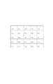
次に、本発明の色シェーディング検査実施例の流れを、図3のフローチャートを使って説明する。まず、検査対象であるデジタルスチルカメラ20で、光源10の均一な面の光(予め設定された所定の輝度値の光)を中央部でホワイトバランスを調整し撮影する(S102)。均一な面の光は前述したように、レンズ21、CCD22、A/D変換23を通じてデジタル信号に変換した後、画像メモリに記録され、通信回路26,31を経て最終的に処理装置30の画像メモリ32に画像データとして記録される(S103)。次に、画像データの輝度または色シェーディングの変化率を数値化するのだが、本実施例では色シェーディングの変化率を、図2のように画面をm×n分割、ここでは5×5=25分割して数値化する一例を説明する。
Next, the flow of the color shading inspection embodiment of the present invention will be described with reference to the flowchart of FIG. First, with the digital
まず、各エリアごとに色差信号の平均値を求める(S104)。色差信号の平均値は、各エリア内の平均的な色つき度合いを表現することができる。例えばx1y1エリアの色差信号の平均値を求める場合は、x1y1エリアの全画素あるいは間引いた画素などで色差信号の平均値を求める。S103で得られた画像がJPEGで色差信号としてCr,Cbを用いる場合、x1y1エリアCrの平均値Cr(ave)とCbの平均値Cb(ave)を算出する。次に各エリアのCrの平均値Cr(ave)とCbの平均値Cb(ave)が、あらかじめ設定してある規格値を満たしているか判定手段34で判定する(S105)。 First, an average value of color difference signals is obtained for each area (S104). The average value of the color difference signal can express the average degree of coloring in each area. For example, when obtaining the average value of the color difference signals in the x1y1 area, the average value of the color difference signals is obtained from all the pixels in the x1y1 area or thinned pixels. When the image obtained in S103 is JPEG and uses Cr and Cb as color difference signals, an average value Cr (ave) of x1y1 area Cr and an average value Cb (ave) of Cb are calculated. Next, the determination means 34 determines whether the average value Cr (ave) of Cr and the average value Cb (ave) of Cb in each area satisfy a preset standard value (S105).
本実施例では
Cr(ave) < Cr(ave規格)
Cb(ave) < Cb(ave規格)
を、全エリアで満たす場合は、この項目の検査は合格とし、S106に進む。全エリア中一つのエリアでも規格値を満たせない場合は、色つき度合いが高いと判断し、検査は不合格と判定する(S109)。S105で合格した場合は、次に各エリアごとに色差信号の標準偏差を求める(S106)。色差信号の標準偏差は、各エリア内の色の変化率を表現することができる。例えば、図4のようにx1y3,x2y4,x3y5エリアで急激に緑からマゼンタに色が変化しているケースを考えると、x1y3,x2y4,x3y5エリアでは図5のようなCrの分布となる(横軸が色の分布、縦軸が各々の色の画素の個数nを表している)。これに対して、色の変化が小さいエリアでは、図6のような分布となるため、図5と図6を比較すると標準偏差が高くなる分布、すなわち横軸の広がりの大きい分布の場合に色の変化率が大きいことがわかる。例えばx1y2エリアの色差信号の標準偏差を求める場合は、x1y2エリアの全画素あるいは間引いた画素などで色差信号の標準偏差を求める。S103で得られた画像がJPEGで、色差信号としてCr,Cbを用いる場合、x1y1エリアCrの標準偏差Cr(stdev)とCbの標準偏差Cb(stdev)を算出する。次に、各エリアのCrの標準偏差Cr(stdev)とCbの標準偏差Cb(stdev)が、あらかじめ設定してある規格値を満たしているかを、判定手段34で判定する(S107)。
In this example, Cr (ave) <Cr (ave standard)
Cb (ave) <Cb (ave standard)
Is satisfied in all areas, the inspection of this item is passed, and the process proceeds to S106. When the standard value cannot be satisfied even in one of all the areas, it is determined that the degree of coloring is high, and the inspection is determined to be unacceptable (S109). If the result is S105, the standard deviation of the color difference signal is obtained for each area (S106). The standard deviation of the color difference signal can express the color change rate in each area. For example, as shown in FIG. 4, when considering a case where the color suddenly changes from green to magenta in the x1y3, x2y4, and x3y5 areas, the distribution of Cr in FIG. 5 is obtained in the x1y3, x2y4, and x3y5 areas (horizontal The axis represents the color distribution, and the vertical axis represents the number n of pixels of each color). On the other hand, since the distribution shown in FIG. 6 is obtained in an area where the color change is small, the color distribution is increased in the case of a distribution in which the standard deviation is higher when FIG. 5 is compared with FIG. It can be seen that the rate of change is large. For example, when obtaining the standard deviation of the color difference signal in the x1y2 area, the standard deviation of the color difference signal is obtained from all the pixels in the x1y2 area or from thinned pixels. When the image obtained in S103 is JPEG and Cr and Cb are used as color difference signals, the standard deviation Cr (stdev) of the x1y1 area Cr and the standard deviation Cb (stdev) of Cb are calculated. Next, the determination means 34 determines whether the standard deviation Cr (stdev) of Cr and the standard deviation Cb (stdev) of Cb in each area satisfy a preset standard value (S107).
本実施例では
Cr(stdev) < Cr(stdev規格)
Cb(stdev) < Cb(stdev規格)
を、全エリアで満たす場合は最終的に検査は合格とし(S108)、全エリア中で一つのエリアでも規格値を満たせない場合は、色の変化率が大きいと判断し、検査は不合格と判定する(S109)。
In this embodiment, Cr (stdev) <Cr (stdev standard)
Cb (stdev) <Cb (stdev standard)
If all the areas are satisfied, the inspection is finally accepted (S108). If one of the all areas cannot satisfy the standard value, it is determined that the color change rate is large, and the inspection is rejected. Determination is made (S109).
なお、本実施例では、通信回路26、31によって画像の送受信を行った後に、検査するように構成した。本実施例では、この検査結果に基づいて合格か、不合格かを判定するが、撮像装置20と、処理装置30が一体型となっており、通常撮影時以外の時に、上記の方法で検査を行い、検査結果に基づいて、画像データの補正を行い出力する構成としてもよい。
In the present embodiment, the
また、本実施例では色シェーディング検査実施例の流れを図3のフローチャートを用いて説明したが、輝度シェーディング検査の場合には、前記各領域の輝度値の平均値を算出し、各エリアの平均値と規格値を比較して、基準値以上の場合には検査不合格とし、基準値以下の場合に輝度値の標準偏差を算出して各エリアの標準偏差と規格値を比較して、検査の合否判定を行なう。つまり、輝度信号も、色信号も、同様の手順を踏んで、それぞれの撮像装置または撮像素子に適応したシェーディングの判定を行なうことが可能となる。 Further, in the present embodiment, the flow of the color shading inspection embodiment has been described with reference to the flowchart of FIG. 3, but in the case of the luminance shading inspection, the average value of the luminance values of the respective areas is calculated and the average of the areas is calculated. The standard value is compared with the standard value, and if it is above the reference value, the test is rejected. If the standard value is below the standard value, the standard deviation of the brightness value is calculated and the standard deviation of each area is compared with the standard value. The pass / fail judgment is performed. In other words, the luminance signal and the color signal can be subjected to the same procedure, and shading determination suitable for each imaging device or imaging element can be performed.
(実施例2)
本発明の色シェーディング補正の補正係数算出方法の実施例を、図面に基づいて説明する。図7は本実施例の撮像装置で、ここではデジタルスチルカメラの構成を示すブロック図である。図8は本実施例による色シェーディング補正係数算出方法のフローチャート、図10は実施例1で説明した図2の画像データを、色の変化率の高いエリアで細分割した図である。
(Example 2)
An embodiment of a correction coefficient calculation method for color shading correction according to the present invention will be described with reference to the drawings. FIG. 7 shows an image pickup apparatus according to the present embodiment, which is a block diagram showing a configuration of a digital still camera. FIG. 8 is a flowchart of a color shading correction coefficient calculation method according to the present embodiment, and FIG. 10 is a diagram obtained by subdividing the image data illustrated in FIG.
まず、図7の各部の機能を説明する。10は均一な面の光を発生させる光源である。20は撮像装置で、本実施例ではデジタルスチルカメラである。内部の機能を詳述すると、22は光を電気信号へ換する撮像素子、本実施例ではCCD、21は光源10からの光をCCD22へ集光するレンズ、23はCCD22から出力されるアナログ映像信号をデジタル映像信号へ変換するA/D変換回路、24はデジタルに変換された画像データを記憶する画像メモリ、25は撮像装置を制御する制御手段、33は画像データの輝度または色シェーディングの変化率を数値化する変化率算出手段で、本実施例では25、33はCPU37上のファームウェアで各機能を実現している。
First, the function of each part in FIG. 7 will be described. A
次に、本発明の実施例の流れを図8のフローチャートを使って説明する。まず、デジタルスチルカメラ20で光源10の均一な面の光を、中央部でホワイトバランスを調整して撮影する(S202)。均一な面の光は前述したように、レンズ21、CCD22、A/D変換23を通じてデジタル信号に変換され、最終的に画像メモリ21に記録される(S203)。次に、実施例1で説明した25分割画像(図2)に対して、各エリア毎に色差信号の標準偏差を求める。色差信号の標準偏差は、実施例1で前述したように、各エリア内の色の変化率を表現することができる。例えばx1y2エリアの色差信号の標準偏差を求める場合は、x1y2エリアの全画素あるいは間引いた画素などで、色差信号の標準偏差を求める。S203で得られた画像がJPEGで、色差信号としてCr,Cbを用いる場合、x1y1エリアCrの標準偏差Cr(stdev)とCbの標準偏差Cb(stdev)を算出する(S204)。次に、本実施例では、各エリアのCrの標準偏差Cr(stdev)とCbの標準偏差Cb(stdev)をそれぞれを2乗した和の平方根を計算する(S205)。
C=√(Cr^2+Cb^2)
Next, the flow of the embodiment of the present invention will be described with reference to the flowchart of FIG. First, light of a uniform surface of the
C = √ (Cr ^ 2 + Cb ^ 2)
以上の演算を、全てのエリアで行い、最も色の変化率の高いエリアのCmaxを抽出する(S206)。最後に、Cmaxに応じたシェーディング補正係数を決定する。本実施例では、完全補正すなわち100%補正時のC100%をあらかじめ設定しておき、
Cmax/C100% ただし、Cmax/C100%<=1
をシェーディング補正係数として設定する(S207)。
The above calculation is performed for all areas, and Cmax of the area having the highest color change rate is extracted (S206). Finally, a shading correction coefficient corresponding to Cmax is determined. In this embodiment, C 100% at the time of complete correction, that is, 100% correction is set in advance,
Cmax / C 100% where Cmax / C 100% <= 1
Is set as a shading correction coefficient (S207).
なお、本実施例では色シェーディング補正について説明したが、実施例1と同様、この手順は、輝度シェーディング補正にも適用できる。 Although the color shading correction has been described in the present embodiment, this procedure can also be applied to the luminance shading correction as in the first embodiment.
本実施例で求めたシェーディング補正係数を用いて、シェーディング補正を行なえば、領域を分割して領域ごとに補正していること、また、各エリア内の輝度または色の変化率を数値化して補正係数を求めていることから、輝度および色が急峻に変化する場合等に、より人の視覚特性に合致した精度の高いシェーディング補正が可能となる。また、必要最小限のメモリ容量で、補正誤差の小さいシェーディング補正が可能となる。 If shading correction is performed using the shading correction coefficient obtained in this embodiment, the area is divided and corrected for each area, and the luminance or color change rate in each area is converted into a numerical value for correction. Since the coefficient is obtained, it is possible to perform highly accurate shading correction that matches the human visual characteristics when the luminance and color change sharply. Further, shading correction with a small correction error can be performed with the minimum necessary memory capacity.
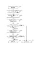
本実施例のデジタルスチルカメラにおける、色シェーディング補正の流れを、図9のフローチャートを使って説明する。まず、デジタルスチルカメラ20で光源10の均一な面の光を中央部でホワイトバランスを調整し撮影する(S302)。均一な面の光は前述したように、レンズ21、CCD22、A/D変換23を通じてデジタル信号に変換され、最終的に画像メモリ24に記録される(S303)。次に、25分割した各エリアごとに色差信号の標準偏差を求める。色差信号の標準偏差は、実施例1で前述したように各エリア内の色の変化率を表現することができる。例えば、x1y2エリアの色差信号の標準偏差を求める場合は、x1y2エリアの全画素あるいは間引いた画素などで色差信号の標準偏差を求める。S303で得られた画像がJPEGで色差信号としてCr,Cbを用いる場合、x1y1エリアCrの標準偏差Cr(stdev)とCbの標準偏差Cb(stdev)を算出する(S304)。次に、本実施例では各エリアのCrの標準偏差Cr(stdev)とCbの標準偏差Cb(stdev)をそれぞれを2乗した和の平方根を計算する(S305)。
Cxnyn=√(Cr^2+Cb^2)
The flow of color shading correction in the digital still camera of the present embodiment will be described using the flowchart of FIG. First, light of a uniform surface of the
C xnyn = √ (Cr ^ 2 + Cb ^ 2)
次にS305で算出したCxnynが、あらかじめ設定した基準値を超えていないか判定する(S306)。基準値を超えていない場合は、画像の色の変化率が基準値よりも小さいと判断し、所定の25分割のシェーディング補正係数データを基に補正を行う。基準値を超えている場合は、色の変化率が基準値よりも大きいと判断し、そのエリアを図10のように画像データの測定領域を細分割する(S307)。ここではx1y3,x2y4,x3y5の各エリアで色の変化率が大きく基準値を超えたと判断し、本実施例では4分割している。細分割したエリアを追加した34分割の画像データを演算し、この34分割のシェーディング補正係数データと線形補間による補正データを用いて補正を行う。上記のように、変化率が基準値を超えたと判断された場合には、更に画像領域を分割して補正を行うことにより、急峻な色の変化で発生するシェーディング補正誤差を最小とすることが可能となり、なおかつ、必要な箇所のみ細分化可能なため、補正データも削減可能となる(S308)。 Next, it is determined whether C xnyn calculated in S305 exceeds a preset reference value (S306). If the reference value is not exceeded, it is determined that the rate of change in the color of the image is smaller than the reference value, and correction is performed based on predetermined 25-division shading correction coefficient data. If it exceeds the reference value, it is determined that the color change rate is larger than the reference value, and the measurement area of the image data is subdivided into the area as shown in FIG. 10 (S307). Here, it is determined that the color change rate greatly exceeds the reference value in each of the areas x1y3, x2y4, and x3y5, and in this embodiment, the area is divided into four. 34-division image data to which the subdivided area is added is calculated, and correction is performed using the 34-division shading correction coefficient data and correction data obtained by linear interpolation. As described above, when it is determined that the rate of change exceeds the reference value, the shading correction error caused by the steep color change can be minimized by further correcting the image area. Moreover, since only necessary portions can be subdivided, correction data can be reduced (S308).
なお、実施例2では各々の領域ごとに変化率を求め、必要であれば領域を分割してシェーディング補正を行ったが、必要であれば領域を分割して、各々の領域ごとの変化率をもとにあらかじめ補正値を記憶手段に記憶しておいて、前記あらかじめ記憶された補正値を基に、シェーディング補正を行うように構成しても良い。 In the second embodiment, the change rate is obtained for each region, and the shading correction is performed by dividing the region if necessary. However, if necessary, the region is divided and the change rate for each region is calculated. The correction value may be stored in the storage unit in advance, and shading correction may be performed based on the correction value stored in advance.
10 光源
20 デジタルスチルカメラ
21 レンズ
22 CCD
23 A/D変換回路
24 画像メモリ
25 制御手段
26 通信回路
30 色むら、色シェーディング処理装置
31 通信回路
32 画像メモリ
33 変化率算出手段
34 判定手段
35 制御手段
10
23 A /
Claims (1)
前記複数の色差信号の標準偏差の2乗和の平方根を算出する第2の算出工程と、
前記2乗和の平方根が所定値より大きい領域を細分割する細分割工程と、
前記複数の領域に細分割した領域を追加した各領域においてシェーディング補正係数を求め、前記シェーディング補正係数を用いて画像データを補正する補正工程と、
を有することを特徴とするシェーディング処理方法。 A first calculation step of calculating a standard deviation of a plurality of color difference signals for each of a plurality of regions in image data obtained by imaging a uniform surface;
A second calculation step of calculating a square root of a square sum of standard deviations of the plurality of color difference signals;
A subdivision step of subdividing an area where the square root of the square sum is greater than a predetermined value;
A correction step of obtaining a shading correction coefficient in each area obtained by adding areas subdivided into the plurality of areas, and correcting image data using the shading correction coefficient;
A shading processing method characterized by comprising:
Priority Applications (1)
| Application Number | Priority Date | Filing Date | Title |
|---|---|---|---|
| JP2004123869A JP4579570B2 (en) | 2004-04-20 | 2004-04-20 | Shading method |
Applications Claiming Priority (1)
| Application Number | Priority Date | Filing Date | Title |
|---|---|---|---|
| JP2004123869A JP4579570B2 (en) | 2004-04-20 | 2004-04-20 | Shading method |
Publications (2)
| Publication Number | Publication Date |
|---|---|
| JP2005309651A JP2005309651A (en) | 2005-11-04 |
| JP4579570B2 true JP4579570B2 (en) | 2010-11-10 |
Family
ID=35438395
Family Applications (1)
| Application Number | Title | Priority Date | Filing Date |
|---|---|---|---|
| JP2004123869A Expired - Fee Related JP4579570B2 (en) | 2004-04-20 | 2004-04-20 | Shading method |
Country Status (1)
| Country | Link |
|---|---|
| JP (1) | JP4579570B2 (en) |
Families Citing this family (10)
| Publication number | Priority date | Publication date | Assignee | Title |
|---|---|---|---|---|
| JP4739017B2 (en) * | 2005-12-28 | 2011-08-03 | キヤノン株式会社 | Color evaluation processing method, color evaluation processing device, computer program, and recording medium |
| JP2007267079A (en) * | 2006-03-29 | 2007-10-11 | Murata Mach Ltd | Shading data inspection method and image reader |
| KR100793938B1 (en) | 2006-06-14 | 2008-01-16 | 주식회사 아이닉스 | Shadow Compensation Device and Compensation Method |
| JP4433017B2 (en) | 2007-08-31 | 2010-03-17 | ブラザー工業株式会社 | Image processing apparatus and image processing program |
| JP4442664B2 (en) | 2007-08-31 | 2010-03-31 | ブラザー工業株式会社 | Image processing apparatus, image processing method, and image processing program |
| US8174731B2 (en) | 2007-08-31 | 2012-05-08 | Brother Kogyo Kabushiki Kaisha | Image processing device outputting image for selecting sample image for image correction |
| US8159716B2 (en) | 2007-08-31 | 2012-04-17 | Brother Kogyo Kabushiki Kaisha | Image processing device performing image correction by using a plurality of sample images |
| US8094343B2 (en) | 2007-08-31 | 2012-01-10 | Brother Kogyo Kabushiki Kaisha | Image processor |
| JP4793356B2 (en) | 2007-08-31 | 2011-10-12 | ブラザー工業株式会社 | Image processing apparatus and image processing program |
| CN119811271B (en) * | 2025-01-08 | 2026-03-03 | 山西高科华杰光电科技股份有限公司 | A method and system for automatic correction of uneven surfaces of an MLED display screen |
Family Cites Families (2)
| Publication number | Priority date | Publication date | Assignee | Title |
|---|---|---|---|---|
| JPH04207665A (en) * | 1990-11-30 | 1992-07-29 | Omron Corp | Image processor |
| JP3752448B2 (en) * | 2001-12-05 | 2006-03-08 | オリンパス株式会社 | Image display system |
-
2004
- 2004-04-20 JP JP2004123869A patent/JP4579570B2/en not_active Expired - Fee Related
Also Published As
| Publication number | Publication date |
|---|---|
| JP2005309651A (en) | 2005-11-04 |
Similar Documents
| Publication | Publication Date | Title |
|---|---|---|
| JP4378746B2 (en) | Digital image sensor and method capable of detecting defective pixels | |
| JP4374488B2 (en) | Digital image system and method for combining demosaicing and bad pixel correction | |
| KR101442313B1 (en) | Camera sensor correction | |
| EP1528797B1 (en) | Image processing apparatus, image-taking system and image processing method | |
| US20020163583A1 (en) | System and method for capturing color images that extends the dynamic range of an image sensor | |
| CN102577355B (en) | The method of the defect of predicted picture acquisition system and related system thereof | |
| US8212899B2 (en) | Imaging apparatus capable of highly accurate defective pixel correction processing | |
| JP2016057638A (en) | Method of generating focus signal from plurality of edge widths | |
| CN102970463A (en) | Image processing device, image processing method and program | |
| JP4579570B2 (en) | Shading method | |
| JP4728265B2 (en) | Noise characteristic measuring apparatus and noise characteristic measuring method | |
| JP2004320128A (en) | Defective pixel correction device | |
| US20030174221A1 (en) | Signal processing device for reducing noise of image signal, signal processing program, and signal processing method | |
| JP2011114473A (en) | Pixel defect correction device | |
| US8717465B2 (en) | Blemish detection sytem and method | |
| JP2001245307A (en) | Imaging device | |
| US7986354B2 (en) | Method for correcting pixel defect of image pickup device | |
| JP2011114760A (en) | Method for inspecting camera module | |
| KR100645856B1 (en) | Signal processing method and image acquisition device | |
| JP4910412B2 (en) | Appearance inspection method | |
| JP4244046B2 (en) | Image processing method and image processing apparatus | |
| JP2002271806A (en) | Pixel defect signal correction circuit for CCD image sensor | |
| JP6519276B2 (en) | Image pickup apparatus and defect pixel correction method | |
| KR20100037339A (en) | Apparatus and method for correcting defect pixels | |
| JP2001016599A (en) | Pixel defect correction device, pixel defect detector and pixel defect detecting method |
Legal Events
| Date | Code | Title | Description |
|---|---|---|---|
| A621 | Written request for application examination |
Free format text: JAPANESE INTERMEDIATE CODE: A621 Effective date: 20070413 |
|
| RD04 | Notification of resignation of power of attorney |
Free format text: JAPANESE INTERMEDIATE CODE: A7424 Effective date: 20100201 |
|
| A977 | Report on retrieval |
Free format text: JAPANESE INTERMEDIATE CODE: A971007 Effective date: 20100331 |
|
| A131 | Notification of reasons for refusal |
Free format text: JAPANESE INTERMEDIATE CODE: A131 Effective date: 20100406 |
|
| A521 | Request for written amendment filed |
Free format text: JAPANESE INTERMEDIATE CODE: A523 Effective date: 20100531 |
|
| RD01 | Notification of change of attorney |
Free format text: JAPANESE INTERMEDIATE CODE: A7421 Effective date: 20100630 |
|
| TRDD | Decision of grant or rejection written | ||
| A01 | Written decision to grant a patent or to grant a registration (utility model) |
Free format text: JAPANESE INTERMEDIATE CODE: A01 Effective date: 20100824 |
|
| A01 | Written decision to grant a patent or to grant a registration (utility model) |
Free format text: JAPANESE INTERMEDIATE CODE: A01 |
|
| A61 | First payment of annual fees (during grant procedure) |
Free format text: JAPANESE INTERMEDIATE CODE: A61 Effective date: 20100826 |
|
| FPAY | Renewal fee payment (event date is renewal date of database) |
Free format text: PAYMENT UNTIL: 20130903 Year of fee payment: 3 |
|
| R150 | Certificate of patent or registration of utility model |
Free format text: JAPANESE INTERMEDIATE CODE: R150 |
|
| LAPS | Cancellation because of no payment of annual fees |