JP4576552B2 - Radial flow gas phase reactor for reducing the nitrogen oxide content of gases - Google Patents
Radial flow gas phase reactor for reducing the nitrogen oxide content of gases Download PDFInfo
- Publication number
- JP4576552B2 JP4576552B2 JP2002567447A JP2002567447A JP4576552B2 JP 4576552 B2 JP4576552 B2 JP 4576552B2 JP 2002567447 A JP2002567447 A JP 2002567447A JP 2002567447 A JP2002567447 A JP 2002567447A JP 4576552 B2 JP4576552 B2 JP 4576552B2
- Authority
- JP
- Japan
- Prior art keywords
- catalyst
- gas
- catalyst bed
- reactor
- inlet
- Prior art date
- Legal status (The legal status is an assumption and is not a legal conclusion. Google has not performed a legal analysis and makes no representation as to the accuracy of the status listed.)
- Expired - Fee Related
Links
Images


Classifications
-
- B—PERFORMING OPERATIONS; TRANSPORTING
- B01—PHYSICAL OR CHEMICAL PROCESSES OR APPARATUS IN GENERAL
- B01D—SEPARATION
- B01D53/00—Separation of gases or vapours; Recovering vapours of volatile solvents from gases; Chemical or biological purification of waste gases, e.g. engine exhaust gases, smoke, fumes, flue gases, aerosols
- B01D53/34—Chemical or biological purification of waste gases
- B01D53/46—Removing components of defined structure
- B01D53/54—Nitrogen compounds
- B01D53/56—Nitrogen oxides
-
- B—PERFORMING OPERATIONS; TRANSPORTING
- B01—PHYSICAL OR CHEMICAL PROCESSES OR APPARATUS IN GENERAL
- B01D—SEPARATION
- B01D53/00—Separation of gases or vapours; Recovering vapours of volatile solvents from gases; Chemical or biological purification of waste gases, e.g. engine exhaust gases, smoke, fumes, flue gases, aerosols
- B01D53/34—Chemical or biological purification of waste gases
- B01D53/74—General processes for purification of waste gases; Apparatus or devices specially adapted therefor
- B01D53/86—Catalytic processes
- B01D53/8621—Removing nitrogen compounds
- B01D53/8625—Nitrogen oxides
- B01D53/8628—Processes characterised by a specific catalyst
-
- B—PERFORMING OPERATIONS; TRANSPORTING
- B01—PHYSICAL OR CHEMICAL PROCESSES OR APPARATUS IN GENERAL
- B01D—SEPARATION
- B01D53/00—Separation of gases or vapours; Recovering vapours of volatile solvents from gases; Chemical or biological purification of waste gases, e.g. engine exhaust gases, smoke, fumes, flue gases, aerosols
- B01D53/34—Chemical or biological purification of waste gases
- B01D53/74—General processes for purification of waste gases; Apparatus or devices specially adapted therefor
- B01D53/86—Catalytic processes
- B01D53/8621—Removing nitrogen compounds
- B01D53/8625—Nitrogen oxides
- B01D53/8631—Processes characterised by a specific device
-
- B—PERFORMING OPERATIONS; TRANSPORTING
- B01—PHYSICAL OR CHEMICAL PROCESSES OR APPARATUS IN GENERAL
- B01D—SEPARATION
- B01D53/00—Separation of gases or vapours; Recovering vapours of volatile solvents from gases; Chemical or biological purification of waste gases, e.g. engine exhaust gases, smoke, fumes, flue gases, aerosols
- B01D53/34—Chemical or biological purification of waste gases
- B01D53/74—General processes for purification of waste gases; Apparatus or devices specially adapted therefor
- B01D53/86—Catalytic processes
- B01D53/88—Handling or mounting catalysts
- B01D53/885—Devices in general for catalytic purification of waste gases
-
- B—PERFORMING OPERATIONS; TRANSPORTING
- B01—PHYSICAL OR CHEMICAL PROCESSES OR APPARATUS IN GENERAL
- B01J—CHEMICAL OR PHYSICAL PROCESSES, e.g. CATALYSIS OR COLLOID CHEMISTRY; THEIR RELEVANT APPARATUS
- B01J23/00—Catalysts comprising metals or metal oxides or hydroxides, not provided for in group B01J21/00
- B01J23/16—Catalysts comprising metals or metal oxides or hydroxides, not provided for in group B01J21/00 of arsenic, antimony, bismuth, vanadium, niobium, tantalum, polonium, chromium, molybdenum, tungsten, manganese, technetium or rhenium
- B01J23/20—Vanadium, niobium or tantalum
- B01J23/22—Vanadium
-
- B—PERFORMING OPERATIONS; TRANSPORTING
- B01—PHYSICAL OR CHEMICAL PROCESSES OR APPARATUS IN GENERAL
- B01J—CHEMICAL OR PHYSICAL PROCESSES, e.g. CATALYSIS OR COLLOID CHEMISTRY; THEIR RELEVANT APPARATUS
- B01J35/00—Catalysts, in general, characterised by their form or physical properties
- B01J35/50—Catalysts, in general, characterised by their form or physical properties characterised by their shape or configuration
- B01J35/58—Fabrics or filaments
-
- B—PERFORMING OPERATIONS; TRANSPORTING
- B01—PHYSICAL OR CHEMICAL PROCESSES OR APPARATUS IN GENERAL
- B01J—CHEMICAL OR PHYSICAL PROCESSES, e.g. CATALYSIS OR COLLOID CHEMISTRY; THEIR RELEVANT APPARATUS
- B01J8/00—Chemical or physical processes in general, conducted in the presence of fluids and solid particles; Apparatus for such processes
- B01J8/02—Chemical or physical processes in general, conducted in the presence of fluids and solid particles; Apparatus for such processes with stationary particles, e.g. in fixed beds
- B01J8/0207—Chemical or physical processes in general, conducted in the presence of fluids and solid particles; Apparatus for such processes with stationary particles, e.g. in fixed beds the fluid flow within the bed being predominantly horizontal
- B01J8/0214—Chemical or physical processes in general, conducted in the presence of fluids and solid particles; Apparatus for such processes with stationary particles, e.g. in fixed beds the fluid flow within the bed being predominantly horizontal in a cylindrical annular shaped bed
-
- B—PERFORMING OPERATIONS; TRANSPORTING
- B01—PHYSICAL OR CHEMICAL PROCESSES OR APPARATUS IN GENERAL
- B01J—CHEMICAL OR PHYSICAL PROCESSES, e.g. CATALYSIS OR COLLOID CHEMISTRY; THEIR RELEVANT APPARATUS
- B01J2208/00—Processes carried out in the presence of solid particles; Reactors therefor
- B01J2208/00796—Details of the reactor or of the particulate material
- B01J2208/00823—Mixing elements
- B01J2208/00831—Stationary elements
- B01J2208/00849—Stationary elements outside the bed, e.g. baffles
-
- B—PERFORMING OPERATIONS; TRANSPORTING
- B01—PHYSICAL OR CHEMICAL PROCESSES OR APPARATUS IN GENERAL
- B01J—CHEMICAL OR PHYSICAL PROCESSES, e.g. CATALYSIS OR COLLOID CHEMISTRY; THEIR RELEVANT APPARATUS
- B01J2219/00—Chemical, physical or physico-chemical processes in general; Their relevant apparatus
- B01J2219/19—Details relating to the geometry of the reactor
- B01J2219/194—Details relating to the geometry of the reactor round
- B01J2219/1941—Details relating to the geometry of the reactor round circular or disk-shaped
- B01J2219/1943—Details relating to the geometry of the reactor round circular or disk-shaped cylindrical
-
- B—PERFORMING OPERATIONS; TRANSPORTING
- B01—PHYSICAL OR CHEMICAL PROCESSES OR APPARATUS IN GENERAL
- B01J—CHEMICAL OR PHYSICAL PROCESSES, e.g. CATALYSIS OR COLLOID CHEMISTRY; THEIR RELEVANT APPARATUS
- B01J2219/00—Chemical, physical or physico-chemical processes in general; Their relevant apparatus
- B01J2219/19—Details relating to the geometry of the reactor
- B01J2219/194—Details relating to the geometry of the reactor round
- B01J2219/1941—Details relating to the geometry of the reactor round circular or disk-shaped
- B01J2219/1946—Details relating to the geometry of the reactor round circular or disk-shaped conical
-
- B—PERFORMING OPERATIONS; TRANSPORTING
- B01—PHYSICAL OR CHEMICAL PROCESSES OR APPARATUS IN GENERAL
- B01J—CHEMICAL OR PHYSICAL PROCESSES, e.g. CATALYSIS OR COLLOID CHEMISTRY; THEIR RELEVANT APPARATUS
- B01J35/00—Catalysts, in general, characterised by their form or physical properties
- B01J35/50—Catalysts, in general, characterised by their form or physical properties characterised by their shape or configuration
- B01J35/56—Foraminous structures having flow-through passages or channels, e.g. grids or three-dimensional [3D] monoliths
Landscapes
- Chemical & Material Sciences (AREA)
- Engineering & Computer Science (AREA)
- Chemical Kinetics & Catalysis (AREA)
- Environmental & Geological Engineering (AREA)
- Health & Medical Sciences (AREA)
- Analytical Chemistry (AREA)
- General Chemical & Material Sciences (AREA)
- Oil, Petroleum & Natural Gas (AREA)
- Biomedical Technology (AREA)
- Organic Chemistry (AREA)
- Materials Engineering (AREA)
- Physics & Mathematics (AREA)
- Fluid Mechanics (AREA)
- Exhaust Gas Treatment By Means Of Catalyst (AREA)
- Catalysts (AREA)
- Devices And Processes Conducted In The Presence Of Fluids And Solid Particles (AREA)
- Treating Waste Gases (AREA)
Description
本発明はガス、特に燃料の燃焼で生じた煙道ガス中の窒素酸化物含量を接触的に減少させる化学反応器に関する。 The present invention relates to a chemical reactor for catalytically reducing the nitrogen oxide content in flue gases produced by the combustion of gases, particularly fuels .
種々の工業プロセスでの燃料の燃焼ではしばしば望ましくない窒素の酸化物(NOx)を生じ、それは通常一酸化窒素(NO)及び二酸化窒素(NO2)の形態にある。高い燃焼温度はより多くのNOxを生ずる傾向にある。NOxは環境にとって危険なので、燃料の燃焼を含む工業プロセスで生ずるガス、特に電力プラント、熱分解炉、焼却炉、内燃機関、冶金プラント、肥料プラント及び化学プラントから生ずるガス中のNOxの放出を減少させる努力がなされている。 Oxides of nitrogen often undesirable in fuel combustion in various industrial processes produce (NOx), it is in the form of normal nitric oxide (NO) and nitrogen dioxide (NO 2). High combustion temperatures tend to produce more NOx. NOx is hazardous to the environment, reducing emissions of NOx in gases produced by industrial processes, including fuel combustion, especially gases from power plants, pyrolysis furnaces, incinerators, internal combustion engines, metallurgical plants, fertilizer plants and chemical plants Efforts are being made.
煙道ガスのNOx含量を選択的に減らす方法は公知である。一般に、これらの方法には、所望により触媒の存在下に、NOxを還元剤と反応させる方法が含まれる。アンモニアや尿素等の還元剤を用いるNOxの選択的非接触還元(SNCR)では、たとえば約1600〜2100°F(871〜1149℃)といった比較的高温を必要とする。
また、NOxのアンモニアでの還元は、選択的接触還元(SCR)として知られるプロセスで、たとえば約500〜950°F(260〜510℃)といったより低い温度で接触的に行うことができる。
Methods for selectively reducing the NOx content of flue gas are known. In general, these methods include a method of reacting NOx with a reducing agent, optionally in the presence of a catalyst. Selective non-contact reduction (SNCR) of NOx using a reducing agent such as ammonia or urea requires a relatively high temperature, for example, about 1600-2100 ° F. (871-1149 ° C.).
Also, the reduction of NOx with ammonia can be carried out catalytically at lower temperatures, such as about 500-950 ° F. (260-510 ° C.), a process known as selective catalytic reduction (SCR).
従来知られたSCR法と装置を用いる煙道ガスの処理での1つの問題はNOxの十分な除去を達成するに要する設備の重量と容積が地上レベルに配する必要があるということである。多くの工業プラントでは公的規制が厳しくなるにつれてその規制に適合するためにNOx除去(脱NOx)設備を改造することが求められる。しかしdeNOx系の物理的なかさ高さが原因して、煙道ガスを処理のために一旦地上レベルに迂回させ次いで大気への排気用に煙突にもどされねばならない。このようなシステムの高コストを避けるために、煙突に直接取りつけることが可能な比較的軽量の脱NOxユニットを提供することが望まれる。 One problem with the treatment of flue gases using the previously known SCR method and apparatus is that the equipment weight and volume required to achieve sufficient removal of NOx must be at ground level. In many industrial plants, as public regulations become stricter, it is required to modify NOx removal (deNOx) equipment in order to meet the regulations. However, due to the physical bulk of the deNOx system, the flue gas must be diverted to ground level for processing and then returned to the chimney for exhaust to the atmosphere. In order to avoid the high cost of such a system, it is desirable to provide a relatively lightweight de-NOx unit that can be attached directly to the chimney.
本発明の目的は煙突に直接取りつけることが可能な脱NOxユニットを提供することにある。 An object of the present invention is to provide a deNOx unit that can be directly attached to a chimney.
本発明によれば、(a)内側表面と外側表面、初期濃度の窒素酸化物をもつ入口ガス流を受け入れるガス流入口及び入口ガス流の窒素酸化物濃度よりも低い窒素酸化物濃度の処理済ガスを排出するガス流出口をもつ胴部、(b)入口ガス流に還元剤を導入するための少なくとも1のインゼクタ、(c)胴部内のインゼクタの近傍又は下流にあり、入口ガス流中の窒素酸化物を選択的に接触還元して窒素酸化物濃度の減少した処理済ガスを生ずるための少なくとも1の窒素酸化物転化触媒を含有すると共に軸方向の通路を定める内部壁と胴部の内部表面から離れている外部壁とをもつ触媒床、及び(d)還元剤を含有する入口ガスの流れを触媒床を通して放射状に方向づけ、処理済のガスを触媒床を通してその放射状通路から放出しそしてガス流出口を通して胴部から排出する入口ガス流デフレクタからなることを特徴とするガス流中の窒素酸化物の化学変換用の放射流(ラジアルフロー)気相反応器が提供される。 According to the present invention, (a) an inner surface and an outer surface, a gas inlet that receives an inlet gas stream having an initial concentration of nitrogen oxide, and a treated nitrogen oxide concentration that is lower than the nitrogen oxide concentration of the inlet gas stream A barrel having a gas outlet for discharging gas, (b) at least one injector for introducing a reducing agent into the inlet gas stream, (c) near or downstream of the injector in the barrel, in the inlet gas stream Internal walls and body containing at least one nitrogen oxide conversion catalyst for selectively catalytically reducing nitrogen oxides to produce a treated gas with reduced nitrogen oxide concentration and defining an axial passage A catalyst bed with an outer wall remote from the surface, and (d) a flow of inlet gas containing the reducing agent is directed radially through the catalyst bed, the treated gas is discharged from the radial passage through the catalyst bed and the gas Radial flow for the chemical conversion of nitrogen oxides in the gas stream, characterized in that it consists of the inlet gas stream deflector for discharging from the barrel (radial flow) the gas phase reactor is provided through the outlet.
本発明の放射流反応器はガス、特に炉中の化石燃料の燃焼で生ずるガス中のNOxの選択的接触還元用の比較的軽量の設備を提供するものであり、また一般的なデザインの煙突を備えた炉中に容易に組込むことができ、それ故既存の設備の改造に適したものである。 The radiant flow reactor of the present invention provides a relatively lightweight facility for the selective catalytic reduction of NOx in gases, particularly those produced by the combustion of fossil fuels in a furnace, and a chimney of general design. Can be easily integrated into a furnace equipped with a slab and is therefore suitable for retrofitting existing equipment.
以下に本発明の放射流反応器の種々の態様とそこに用いる好ましい触媒配置を図面を参照して説明する。尚すべての量は「約」なる用語で変更しうるものである。また%は特に断りのない限り重量基準で示す。 Hereinafter, various embodiments of the radial flow reactor of the present invention and preferred catalyst arrangements used therein will be described with reference to the drawings. All quantities can be changed by the term “about”. % Is based on weight unless otherwise specified.
触媒床を通るガスの流れに関連して用いる「放射流」なる用語は触媒床の内部から外部への外方向の流れ及び触媒床の外部から触媒床の内部への流れを包含し、ここで触媒床は内側円筒壁と外側円筒壁によって定められる実質上環形状をもつか又はたとえば内側壁及び/又は外側壁が、断面でみて、六角形又は八角形等の多角形状をもっているような環状と同様に機能する形状をもつ。
「窒素酸化物」なる用語はNO、NO2、N2O4、N2O及びそれらの適宜の混合物等の窒素の適宜の酸化物をいい、しばしば「NOx」と表示する。
The term "radial flow" as used in connection with the flow of gas through the catalyst bed includes outward flow from the inside of the catalyst bed to the outside and flow from the outside of the catalyst bed to the inside of the catalyst bed, where The catalyst bed has a substantially annular shape defined by an inner cylindrical wall and an outer cylindrical wall or is similar to an annular shape in which the inner wall and / or the outer wall have a polygonal shape such as a hexagon or an octagon in cross section. It has a shape that functions.
The term “nitrogen oxide” refers to an appropriate oxide of nitrogen, such as NO, NO 2 , N 2 O 4 , N 2 O, and appropriate mixtures thereof, often denoted as “NOx”.
本発明のNOxの選択的接触還元の反応器と方法では、好ましくは還元剤としてアンモニアを用いる。NOxは触媒の存在下にアンモニアと反応して次式(化学量論的バランスで示してはいない)に示すように窒素と水を生ずる:
NOx+NH3→N2+H2O
In the NOx selective catalytic reduction reactor and method of the present invention, ammonia is preferably used as the reducing agent. NOx reacts with ammonia in the presence of a catalyst to produce nitrogen and water as shown in the following formula (not shown in stoichiometric balance):
NOx + NH 3 → N 2 + H 2 O
本発明の脱NOxの方法と装置はNOx含有ガスを処理してそのNOxレベルを低下させることを要する適宜の用途に用いうる。高レベルのNOxを生ずる代表的な燃焼設備の例としては電力プラント、流体接触分解(FCC)レゼネレータ、ガラス炉、熱分解炉等がある。本発明の脱NOx法はエタン、プロパン、ナフサ等の飽和炭化水素供給原料からオレフィン(たとえばエチレン、プロピレン、ブチレン等)を生成する熱分解ユニットに特に好ましく用いられる。しかし、これに限らず望ましくないレベルのNOxを含有するガスを発生する適宜の燃焼設備や方法に用いうるものである。 The de-NOx method and apparatus of the present invention can be used in any application that requires processing a NOx-containing gas to reduce its NOx level. Examples of typical combustion equipment that produces high levels of NOx include power plants, fluid catalytic cracking (FCC) generators, glass furnaces, pyrolysis furnaces, and the like. The de-NOx process of the present invention is particularly preferably used for a pyrolysis unit that produces olefins (for example, ethylene, propylene, butylene, etc.) from saturated hydrocarbon feedstocks such as ethane, propane, and naphtha. However, the present invention is not limited to this, and can be used for an appropriate combustion facility or method for generating a gas containing an undesirable level of NOx.
図1(A及びB)において、放射流気相脱NOx反応器10が供給原料のクラッキング用に約2200°F(1204℃)で操作される放射燃焼室をもつ炉11と12を用いる熱分解系を対象に示されている。各炉はそれぞれの煙突を通って排出される煙道ガスを生ずる。典型的には、各煙突中の煙道ガスの流速は約100,000〜300,000lbs/時(45359〜136078kg/時)である。この煙道ガスは典型的には次の成分を含有する:
窒素 : 60−80vol%
酸素 : 1− 4vol%
水蒸気: 10−25vol%
二酸化炭素: 2−20vol%
窒素酸化物: 50−300ppm
放射室を出る煙道ガスの温度は典型的には約1800°F(982℃)である。各煙突は所望により、対流部13をもち、これは熱回収用に煙道ガスが通る熱交換器をもっている。煙道ガスは典型的には約300〜500°F(149〜260℃)の温度で対流部を出るが、この範囲外の煙道ガス温度を与えるように熱回収プロセスを調節することができる。次いで別々の煙突の煙道ガスを合しファン14で脱NOx系10に移す。ファン14は脱NOx系10中をガスが移動するよう煙道ガスの圧力を増加させる。
In FIGS. 1 (A and B), pyrolysis using a
Nitrogen: 60-80 vol%
Oxygen: 1-4 vol%
Water vapor: 10-25 vol%
Carbon dioxide: 2-20 vol%
Nitrogen oxide: 50-300ppm
The temperature of the flue gas exiting the radiant chamber is typically about 1800 ° F. (982 ° C.). Each chimney optionally has a
本発明の放射流反応器はガスが触媒床に入る前に比較的長いガス流の長さをもたらす。特に対流部と関連して、この長いガス流の長さが触媒床を通るガス流の速度分布をより均一にする助けをする。ガス流はファン出口できびしい速度分布を示すのでこれは重要である。通常の系では、触媒床はファンで起こる不均一な速度分布を補うため約20%以上過剰設計される。この過剰設計は過度に大きく重い触媒床をもたらすが、本発明ではそれを避けることができる。 The radial flow reactor of the present invention provides a relatively long gas flow length before the gas enters the catalyst bed. This long gas flow length, particularly in connection with the convection section, helps to make the gas flow velocity distribution through the catalyst bed more uniform. This is important because the gas flow exhibits a severe speed distribution at the fan exit. In a typical system, the catalyst bed is overdesigned by about 20% or more to compensate for the uneven speed distribution that occurs in the fan. This overdesign results in an overly large and heavy catalyst bed, which can be avoided in the present invention.
図2においてAの一態様では、放射流気相反応器20は内側表面21aと外側表面21bをもつ反応器胴部(シェル)21をもつ。胴部21は初期濃度のNOxを含有する入口ガスを受け入れるガス流入口21cと、減少した濃度のNOxを含有する処理済ガスを排出するガス流出口21dと、ガス流出口21dと連通して処理済ガスを通す通路21eをもつ。
インゼクタ22は還元剤を導入するためのものであり適宜公知のタイプのインゼクタを用いうる。典型的なインゼクタの例としては触媒床の上流の入口ガス流中に配したグリッド状部分がある。このグリッド状部分は均等に分布させた注入ノズルをもつ多孔分散管の集合体を含む。通常還元剤は入口ガスの流れ方向とは反対方向に注入される。好ましい還元剤はアンモニアだが、尿素、アルキルアミンその他の適当な還元剤も用いうる。インゼクタ22は入口21c内又は入口21cの上流に位置しうる。
In one embodiment of FIG. 2A, the radial flow
The
触媒床23は窒素酸化物の選択還元用の少なくとも1の触媒を含有する。選択的接触還元反応の好ましい温度は典型的には約380〜550°F(193〜288℃)、より好ましくは約400〜450°F(204〜232℃)である。一般に、温度が低いほど多量の触媒が所定レベルのNOx変換の達成に必要となる。煙道ガス温度が望ましくないほど低い場合には、煙道ガス温度を上げるためにバーナーその他の熱源を用いうる。また炉系の対流部13はNOxの選択的接触還元に適する温度をもつ煙道ガスを与えるように構成しうる。
The
還元剤の存在下に用いる窒素酸化物の選択的還元用触媒は公知である。これら触媒の典型的で非限定的な例としては、バナジウム、アルミニウム、チタン、タングステン及びモリブデンの酸化物がある。ゼオライトも用いうる。ゼオライトの例としてはプロトンで、又は銅、コバルト、銀、亜鉛又は白金カチオン又はそれらの組み合わせで変成したZSM−5がある。勿論、本発明で用いうる触媒は特定のSCR触媒又は触媒組成物には限定されない。 Catalysts for selective reduction of nitrogen oxides used in the presence of a reducing agent are known. Typical non-limiting examples of these catalysts include vanadium, aluminum, titanium, tungsten and molybdenum oxides. Zeolites can also be used. Examples of zeolites are ZSM-5 modified with protons or with copper, cobalt, silver, zinc or platinum cations or combinations thereof. Of course, the catalyst that can be used in the present invention is not limited to a specific SCR catalyst or catalyst composition.
触媒床23は還元剤を含有する入口ガス流を受け入れるための軸に沿った通路23cを定める内側壁23bをもつ。図示するように、軸通路23cはその長さ全体に亘って実質上均一な直径をもつ内腔の形をもっている。しかし、他の軸通路構造も可能である。たとえば図2のcに示すように、反応器(胴部)50は円錐形の通路53cをもつ円錐形又はフラスト円錐形の触媒床53をもつ。入口ガス流は入口51cに入り、インゼクタ52を通過して直ちに通路に入り、デフレクタ54で偏向されて触媒床53を外方向に放射状に通過する。触媒床53から出ると処理済ガスは出口51dに向かって流れる。図2(A)にもどって、減少した濃度のNOxを含有する処理済ガスは触媒床の外側壁23aから通路23eに出て出口21dに流れる。通路21eは触媒床の外側壁23aと反応器胴部の内側壁21aの間の環状空間によって少なくとも部分的に定められる。
The
触媒床23は通常環形状をしており、好ましくは外側壁23aと内側壁23bは同心円筒体である。または外側壁23aと内側壁23bは、図2(D)に触媒床23’として示すように、八角形、六角形等の多角形でもよい。多角形の触媒床は特に(後記する)MEC触媒での使用に適している。
The
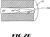
シート状金属等のガス不透過性材料でつくった入口ガス流デフレクタ24を軸通路23c内に配して通路23cに入る入口ガス流の流れが触媒床23を通って外側に放射状に向くようにする。一の好ましい態様において、デフレクタ24はガス流を均一に分配するように上流に頂点をもつ円錐形をしている。さらに別の好ましい態様を示す図2(E)では、デフレクタ24’が触媒床23の軸通路23c内に位置しそしてアーチ形、好ましくはパラボラ形の表面24”と上流の頂点24”’をもつ。パラボラ形のデフレクタ24’は、円錐形のデフレクタに比し、触媒床23を通る放射ガス流がより均一になるという利点をもつ。
An inlet
別の態様を示す図2(B)において、反応器40は広がった側部41hをもつ胴部41をもつ。入口ガス流は入口21cに1以上のインゼクタをもち、触媒床43の外側壁43aと反応器胴部41の内側壁41aの間の空間によって定まる通路41e中に流れる。反応器胴部の内側表面41aと触媒床の外側表面43aは領域41jで収束して環状の触媒床43を通って放射状に内方向に流れる入口ガス流を偏向する通路43eの下流端でガス流バリアを形成する。処理済のガスは触媒床43の内側壁43bから軸通路43cに出る。
In FIG. 2 (B) showing another embodiment, the
さらに別の放射状反応器構造を示す図3において、反応器30は内部空隙をもつ反応器胴部31をもつ。胴部31は内側表面31aと外側表面31b、入口31c、出口31d及び出口31dと連通し処理済のガスが通る通路31eをもつ。インゼクタ32は入口31c内又は入口31cの上流に配されうる。インゼクタ22についての上記記載はまたインゼクタ32にも適用される。
In FIG. 3, which shows yet another radial reactor structure, the
反応器30は少なくとも2個の好ましくは同心的に間隙をあけた触媒床をもつ。図3に示すように、反応器3は同心の環状触媒床33a、33bおよび33cをもつ。中央の触媒床33aは円錐形のデフレクタ34aが位置する軸孔33dをもつ。フラスト円錐形デフレクタ34bは触媒床33aと33bの間の環状空間内に位置しており、フラスト円錐形デフレクタ34cは同様に触媒床33bと33cの間の環状空間内に位置している。環状板34dは、触媒床33cと胴部の内側表面31aの間の環状空間に入ることによって入口ガスが触媒床をバイパスすることを防ぐ。還元剤(たとえばアンモニア)を含有する入口ガスは軸孔33d及び触媒床33a、33bと33b、33cの間の環状空間の底に入りそしてデフレクタ34a、34b、34cによってそれぞれの触媒床を通って放射状に外方向に向けられる。処理済のガスはその後触媒床から通路31eへと出される。
触媒は粒状、モノリス状又は微細加工触媒(MEC)の形でありうる。
The catalyst may be in the form of a granule, monolith or microfabricated catalyst (MEC).
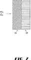
図4において、触媒床40は外側スクリーン41と内側スクリーン42の間の環状空間に配された粒状触媒43を含有する。内側スクリーン42は入口ガスと還元剤を受け入れるための軸流路44を定める内側壁構造を提供する。内側スクリーン42と外側スクリーン41はバージニア州ワイザビルのUSF/Johnson Screensから市販されている。好ましいスクリーンとしてはたとえば溶接したワイヤスクリーン、ループ状のワイヤスクリーン及び織りワイヤスクリーンがある。SCR触媒は粒状でもよく、またチタニア、ゼオライト、炭素、ジルコニア、セラミック、シリカ−アルミナ等の粒状触媒担体上に支持されていてもよい。
In FIG. 4, the
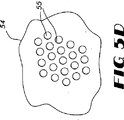
図5(A〜D)において、触媒は複数の積重ねたレンガ状ユニット51を含みうるモノリス50の形状でありうる。モノリス触媒50は複数の平行な流路をもつ。図5(C)に示すように、モノリス52は六角形の流路53をもつハニカム構造をもつ。しかし、この流路は四角形、三角形、T−形等の適宜の他の形もとりうる。図5(D)に環状流路55をもつモノリス54を示す。モノリスは公知の焼結その他の適宜の方法で製造しうる。典型的なSCR触媒はモノリス支持体に含浸して処理のためにガス流が流れる流路の内側表面を被覆してつくられる。
In FIGS. 5A-D, the catalyst may be in the form of a
さらに別の態様において、触媒床は微細加工した触媒(MEC)を含みうる。これは約85%以上の多孔度をもつメッシュ状構造体上にSCR触媒を担持したものである。
MEC触媒は本出願人が2000年7月31日に出願した米国特許第6,534,022に記載されており、その内容をここに引用する。
メッシュ状材料は、ワイヤもしくは繊維メッシュ、金属フェルトもしくはガーゼ、金属繊維フィルタ等の繊維又はワイヤからできている。メッシュ状構造体は単一層からなっていてもよく、またワイヤの2層以上を含んでいてもよく、たとえば、ニットワイヤ構造体、織成ワイヤ構造体等があり、特にワイヤ又は繊維の複数の層からなっていて3次元網状構造体となっているものが好ましい。好ましい態様において、支持構造体は層中でランダムに配向した複数層の繊維からなるものである。1種以上の金属を金属メッシュの製造に用いうる。また繊維と金属を複合して用いることもできる。
In yet another embodiment, the catalyst bed can include a microfabricated catalyst (MEC). This is one in which an SCR catalyst is supported on a mesh-like structure having a porosity of about 85% or more.
MEC catalysts are described in US Pat. No. 6,534,022 , filed July 31, 2000 by the present applicant, the contents of which are hereby incorporated by reference.
The mesh material is made of fiber or wire such as wire or fiber mesh, metal felt or gauze, metal fiber filter. The mesh-like structure may be composed of a single layer or may include two or more layers of wires, such as a knitted wire structure, a woven wire structure, etc., particularly a plurality of wires or fibers. What consists of a layer and becomes a three-dimensional network structure is preferable. In a preferred embodiment, the support structure consists of multiple layers of fibers randomly oriented in the layer. One or more metals can be used in the production of the metal mesh. Further, a fiber and a metal can be used in combination.
メッシュ状構造体が複数の繊維層からなっていて材料の3次元網目構造をつくっている好ましい態様において、これら支持体の厚さは少なくとも5ミクロンで、通常は10mmをこえない。好ましい態様によれば、網目構造体の厚さは少なくとも50ミクロン、より好ましくは少なくとも100ミクロンで、通常は2mmをこえない。
一般に、繊維の複数の層を形成する繊維の厚さ又は直径は約50ミクロン以下、好ましくは約150ミクロン以下、さらに好ましくは約30ミクロン以下である。好ましい態様において、繊維の厚さ又は直径は約8〜約25ミクロンである。
In a preferred embodiment in which the mesh structure is composed of a plurality of fiber layers to form a three-dimensional network of materials, the thickness of these supports is at least 5 microns and usually does not exceed 10 mm. According to a preferred embodiment, the thickness of the network structure is at least 50 microns, more preferably at least 100 microns and usually does not exceed 2 mm.
Generally, the thickness or diameter of the fibers forming the multiple layers of fibers is about 50 microns or less, preferably about 150 microns or less, more preferably about 30 microns or less. In a preferred embodiment, the fiber thickness or diameter is from about 8 to about 25 microns.
3次元メッシュ状構造体は公知方法たとえば米国特許第5,304,330号、米国特許第5,080,962号、米国特許第5,102,745号又は米国特許第5,096,663号に記載の方法で製造しうる。これらのメッシュ状構造体はまた上記公知例記載の方法以外の方法でも製造しうる。 The three-dimensional mesh structure can be obtained by known methods such as US Pat. No. 5,304,330, US Pat. No. 5,080,962, US Pat. No. 5,102,745 or US Pat. No. 5,096,663. It can be produced by the method described. These mesh-like structures can also be produced by methods other than those described in the above known examples.
本発明で用いるメッシュ状構造体は、(メッシュ上に支持した触媒なしで)85%以上、好ましくは87%以上、より好ましくは90%以上の多孔度又はボイド容積を有する。ここでボイド容積はオープン状態の構造体の容積を構造体(開孔とメッシュ材料)の合計容積で割って100をかけて求められる。
一の態様において、粒状支持体を使用せずに、触媒をメッシュ状構造体上に支持する。
The mesh-like structure used in the present invention has a porosity or void volume of 85% or more, preferably 87% or more, more preferably 90% or more (without a catalyst supported on the mesh). Here, the void volume is obtained by dividing the volume of the structure in the open state by the total volume of the structures (holes and mesh material) and multiplying by 100.
In one embodiment, the catalyst is supported on the mesh structure without the use of a particulate support.
別の態様において、窒素酸化物変換用触媒をメッシュ状構造体上に支持した粒状支持体上に支持する。ここで「粒状」又は「粒子」には、球状粒子、長尺粒子、短繊維等が包含される。一般に、触媒を支持する粒子の平均粒子サイズは200ミクロンをこえず、典型的には50ミクロン以下で、大部分の平均粒子サイズが20ミクロンをこえないものが好ましい。一般的には、これら粒子の平均粒子サイズは少なくとも0.002ミクロン、より好ましくは少なくとも0.5ミクロンである。粒状支持体に支持した触媒をメッシュ状構造体上に被覆する場合、触媒支持体の平均粒子サイズは一般的には10ミクロンをこえず、メッシュ構造対中に保持する場合は一般的には150ミクロンをこえない。 In another embodiment, the nitrogen oxide conversion catalyst is supported on a granular support that is supported on a mesh structure. Here, the “granular” or “particle” includes spherical particles, long particles, short fibers, and the like. In general, the average particle size of the particles supporting the catalyst is preferably no more than 200 microns, typically 50 microns or less, with the majority of the average particle size not exceeding 20 microns. Generally, the average particle size of these particles is at least 0.002 microns, more preferably at least 0.5 microns. When a catalyst supported on a particulate support is coated on a mesh structure, the average particle size of the catalyst support typically does not exceed 10 microns and is typically 150 when retained in a mesh structure pair. Does not exceed micron.
本発明の一の態様において、触媒の支持体として機能するメッシュ状構造体は形状をととのえたパッキンの形態をしている。このパッキンは以下の実施例に示すように反応器中の触媒上を流れるガス相の乱れをもたらすように配される。メッシュ状触媒支持構造体は後記するように増大した乱流を付与するために適当な波形をもちうる。またメッシュ状構造体は乱流付与のためにタブのような渦巻発生部材を含みうる。乱流発生部材の存在は放射(及び長さ)方向の混合性を高めまたメッシュを横切る局部圧力差を与えることでメッシュ上に被覆されているか又はメッシュ中に保持されている触媒への接触を促進し、そして流れのための駆動力を生ずる。パッキン構造としてはロールや1以上のシート等のモジュール形状のものもあり、これはモジュール中の流路がチューブの長さ方向に沿うように反応器のチューブ中に配される。ロールは平坦でも波形でもよいシートからつくることができ、このシートは混合促進用にて水や穴をもちうる。シートはまた波形細片にして、細片どうしをチューブのサイズに正確に適合する平坦シートで分けて接着剤、ワイヤ、円筒状平坦シート又はそれらの組合せで互いに保持してもよい。 In one embodiment of the present invention, the mesh-like structure functioning as a catalyst support is in the form of a packing having a shape. This packing is arranged to cause turbulence of the gas phase flowing over the catalyst in the reactor as shown in the examples below. The mesh catalyst support structure may have a suitable corrugation to provide increased turbulence as described below. The mesh-like structure may include a spiral generating member such as a tab for applying turbulent flow. The presence of the turbulence generating member increases the mixing in the radial (and length) direction and provides a local pressure difference across the mesh to provide contact with the catalyst coated on or retained in the mesh. Promotes and creates a driving force for flow. There is a packing structure in the form of a module such as a roll or one or more sheets, which is arranged in the reactor tube such that the flow path in the module is along the length direction of the tube. The roll can be made from a sheet that can be flat or corrugated, and this sheet can have water and holes to facilitate mixing. The sheets may also be corrugated strips that are held together with adhesives, wires, cylindrical flat sheets, or combinations thereof, with the strips separated by flat sheets that accurately match the size of the tube.
触媒を支持するメッシュ状支持体は構造化したシート以外の形状でも用いうる。たとえばリング、粒子、リボン等の形で充填ベルトとして反応器中で用いうる。
メッシュ状構造体に支持した触媒はメッシュ状構造体を形成しているワイヤや繊維上に皮膜として存在していてもよくまたメッシュ状構造体の隙間に存在して保持されていてもよい。
触媒は浸漬やスプレー等の種々の手段でメッシュ状構造体上に被覆できる。触媒粒子はメッシュ状構造体を液体中に分散させた粒子を含む液体コーティング組成物(好ましくはコーティング浴の形)を、コーティング組成物がメッシュ状構造体内に入りその内部及び外部の両方に多孔性皮膜を形成する条件下に、接触させることによってメッシュ状構造体に付与できる。
The mesh support for supporting the catalyst may be used in a shape other than the structured sheet. For example, it can be used in the reactor as a packed belt in the form of rings, particles, ribbons and the like.
The catalyst supported by the mesh structure may be present as a film on the wire or fiber forming the mesh structure, or may be held in the gaps of the mesh structure.
The catalyst can be coated on the mesh structure by various means such as dipping or spraying. The catalyst particles are a liquid coating composition (preferably in the form of a coating bath) containing particles in which the mesh-like structure is dispersed in a liquid, and the coating composition enters the mesh-like structure and is porous both inside and outside. It can give to a mesh-like structure by making it contact on the conditions which form a membrane | film | coat.
触媒は窒素酸化物を変換するに有効な量がメッシュ状構造体上に支持される。一般的にいって、触媒は、メッシュと触媒の合計重量当り、少なくとも5%、好ましくは少なくとも10%存在し、一般的には60%をこえずまたより一般的には40%をこえない。支持触媒を加える前のメッシュ状構造体の多孔度又はボイド容積が87%以上の一態様において、触媒の重量は約5〜約40%であり、また多孔度又はボイド容積が90%以上の場合は支持触媒の重量は約5〜約80%である。 The catalyst is supported on the mesh structure in an amount effective to convert nitrogen oxides. Generally speaking, the catalyst is present at least 5%, preferably at least 10%, generally not exceeding 60%, and more typically not exceeding 40%, based on the combined weight of the mesh and the catalyst. In one embodiment, the porosity or void volume of the mesh structure before adding the supported catalyst is 87% or more, and the weight of the catalyst is about 5 to about 40%, and the porosity or void volume is 90% or more. The weight of the supported catalyst is from about 5 to about 80%.
構造パッキンの種々の態様を以下に述べる。
図6において、パッキン2は複数の多孔度メッシュ材料(MEC材料)からなり、波形が垂直な流れ方向fに対し角度αで斜線で示されている。図6(A)は波形6の代表的な断面を示す。隣接の波形シート8は90°で互い違いになっている。
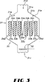
図7では、一般的なモノリスハニカム構造9Bが本発明のMECメッシュ材料9Aと組合されて、NOxのSCR変換用の組合せ触媒床構造をもたらしている。この組合せ構造体は改良された変換率をもたらす。変換率の増加は下流のハニカムモノリスの改良された効率をもたらす構造の組合せによるものと思われる。
Various aspects of the structural packing are described below.
In FIG. 6, the
In FIG. 7, a generic monolith honeycomb structure 9B is combined with the MEC mesh material 9A of the present invention to provide a combined catalyst bed structure for SCR conversion of NOx. This combination structure provides improved conversion rates. The increase in conversion seems to be due to the combination of structures resulting in improved efficiency of the downstream honeycomb monolith.
図8において、MEC材料はシート材料のエレメント826から成形することができ、所望によりそこを通るガスの乱流を増加するために渦巻発生部材を含みうる。図8において、所望により用いる渦巻発生部材846及び848は3角形であり、エレメント826シート材料の平面から折りまげられる。渦巻発生部材846及び848は交互の方向を向き、図8に示すようにシート材料の平面から突出している。波形は幅wをもつ。さらなる乱流を付与するために、渦巻発生部材は圧力差によりMEC材料の孔を通る流対流をさらに促進する。エレメント826の側壁は約90°の角度βで傾いている。根部と山部が直線方向に広がっている。
In FIG. 8, the MEC material may be formed from an
次に本発明の放射流反応器の操作と脱NOx法の実施例を示す。 Next, an example of the operation of the radial flow reactor of the present invention and the deNOx method is shown.
図2(A)に示す放射流気相反応器を次の煙道ガス条件下に2つの炉の煙道ガス流中のNOxの選択的接触還元に用いた:
流速 = 360,000lbs/時(163,293kg/時)
温度 = 360°F(182℃)
NOx含量 = 100ppm
NOxの所望の還元を達成するために十分量のアンモニアを上記煙道ガスに加えた。用いた触媒はV2O5/TiO2触媒を被覆したMECである。10ppmに対する所望のNOx還元90%は約54m3のMEC触媒を必要とする。この容積には内側床直径2m、外側床直径4mm、高さ5.75mの放射流反応器が適している。速度の不均衡分配を補うために追加の容積は必要ない。煙道ガスを処理のために通さねばならない有効床長さはわずかに1mであった。圧力損失は触媒床を通してわずかに約0.17インチ(0.43cm)H2Oであり、これは流れ方向の変化のために0.3インチ(0.76cm)に増加した。
The radial flow gas phase reactor shown in FIG. 2 (A) was used for the selective catalytic reduction of NOx in the two furnace flue gas streams under the following flue gas conditions:
Flow rate = 360,000 lbs / hour (163,293 kg / hour)
Temperature = 360 ° F (182 ° C)
NOx content = 100ppm
Sufficient ammonia was added to the flue gas to achieve the desired reduction of NOx. The catalyst used is a MEC coated with a V 2 O 5 / TiO 2 catalyst. The desired 90% NOx reduction for 10 ppm requires about 54 m 3 of MEC catalyst. A radial flow reactor with an inner bed diameter of 2 m, an outer bed diameter of 4 mm and a height of 5.75 m is suitable for this volume. No additional volume is needed to compensate for the speed imbalance distribution. The effective bed length that the flue gas must pass for treatment was only 1 m. The pressure drop was only about 0.17 inch (0.43 cm) H 2 O through the catalyst bed, which increased to 0.3 inch (0.76 cm) due to the change in flow direction.
上記実施例の放射流反応器とは反対に、同じ90%のNOx還元を達成するために同じ触媒を用いた軸流反応器は3×6×3mの床と速度の不均衡を補うためさらに10−20%の触媒を必要とした。軸流反応器の圧力低下は3インチ(7.62cm)H2Oであり、放射流反応器より10倍大きい。
上記は単に説明のためのものであり本発明を限定するものではない。当業者は請求項に示す本発明の範囲内で適宜の変更が可能である。
Contrary to the radiant flow reactor of the above example, an axial flow reactor using the same catalyst to achieve the same 90% NOx reduction was further improved to compensate for the 3 × 6 × 3 m bed and velocity imbalance. 10-20% catalyst was required. The pressure drop in the axial flow reactor is 3 inches (7.62 cm) H 2 O, 10 times greater than the radial flow reactor.
The above is for illustration only and does not limit the present invention. Those skilled in the art can make appropriate modifications within the scope of the present invention described in the claims.
Claims (13)
Applications Claiming Priority (2)
| Application Number | Priority Date | Filing Date | Title |
|---|---|---|---|
| US09/793,471 US6663839B2 (en) | 2001-02-26 | 2001-02-26 | Radial flow gas phase reactor and method for reducing the nitrogen oxide content of a gas |
| PCT/US2002/005293 WO2002068096A2 (en) | 2001-02-26 | 2002-02-22 | Radial flow gas phase reactor and method for reducing the nitrogen oxide content of a gas |
Publications (2)
| Publication Number | Publication Date |
|---|---|
| JP2004524960A JP2004524960A (en) | 2004-08-19 |
| JP4576552B2 true JP4576552B2 (en) | 2010-11-10 |
Family
ID=25159992
Family Applications (1)
| Application Number | Title | Priority Date | Filing Date |
|---|---|---|---|
| JP2002567447A Expired - Fee Related JP4576552B2 (en) | 2001-02-26 | 2002-02-22 | Radial flow gas phase reactor for reducing the nitrogen oxide content of gases |
Country Status (8)
| Country | Link |
|---|---|
| US (1) | US6663839B2 (en) |
| EP (1) | EP1379321A2 (en) |
| JP (1) | JP4576552B2 (en) |
| KR (1) | KR100868955B1 (en) |
| BR (1) | BR0207520B1 (en) |
| CA (1) | CA2438697C (en) |
| NO (1) | NO20033759L (en) |
| WO (1) | WO2002068096A2 (en) |
Families Citing this family (26)
| Publication number | Priority date | Publication date | Assignee | Title |
|---|---|---|---|---|
| KR100361933B1 (en) * | 1993-09-08 | 2003-02-14 | 라 졸라 파마슈티칼 컴파니 | Chemically defined nonpolymeric bonds form the platform molecule and its conjugate |
| US6762335B1 (en) * | 2000-02-29 | 2004-07-13 | Fina Technology, Inc. | Apparatus for dehydrogenation of ethylbenzene to styrene |
| US20030162848A1 (en) * | 2000-07-25 | 2003-08-28 | Gimpel Frederik Willem Hendrik | Reactor comprising a packed bed of supported catalyst or supported catalyst precursor, and a use of the reactor |
| US20020159923A1 (en) * | 2001-02-26 | 2002-10-31 | Platvoet Erwin M.J. | Gas phase reactor and process for reducing nitrogen oxide in a gas stream |
| FR2823139B1 (en) * | 2001-04-05 | 2004-01-23 | Inst Francais Du Petrole | CATALYST SUPPORT WITH SECANT CHANNEL NETWORKS, CATALYST REACTOR COMPRISING SUCH SUPPORT AND METHOD FOR PRODUCING SUCH CATALYST SUPPORT |
| US6946013B2 (en) | 2002-10-28 | 2005-09-20 | Geo2 Technologies, Inc. | Ceramic exhaust filter |
| US7572311B2 (en) | 2002-10-28 | 2009-08-11 | Geo2 Technologies, Inc. | Highly porous mullite particulate filter substrate |
| US7582270B2 (en) | 2002-10-28 | 2009-09-01 | Geo2 Technologies, Inc. | Multi-functional substantially fibrous mullite filtration substrates and devices |
| US7574796B2 (en) | 2002-10-28 | 2009-08-18 | Geo2 Technologies, Inc. | Nonwoven composites and related products and methods |
| US20050249645A1 (en) * | 2004-05-05 | 2005-11-10 | Eaton Corporation | Catalyst and adsorbant bed configurations suitable for mobile applications |
| US7451849B1 (en) | 2005-11-07 | 2008-11-18 | Geo2 Technologies, Inc. | Substantially fibrous exhaust screening system for motor vehicles |
| US7211232B1 (en) | 2005-11-07 | 2007-05-01 | Geo2 Technologies, Inc. | Refractory exhaust filtering method and apparatus |
| US7682577B2 (en) | 2005-11-07 | 2010-03-23 | Geo2 Technologies, Inc. | Catalytic exhaust device for simplified installation or replacement |
| US7682578B2 (en) | 2005-11-07 | 2010-03-23 | Geo2 Technologies, Inc. | Device for catalytically reducing exhaust |
| US7722828B2 (en) | 2005-12-30 | 2010-05-25 | Geo2 Technologies, Inc. | Catalytic fibrous exhaust system and method for catalyzing an exhaust gas |
| US7444805B2 (en) | 2005-12-30 | 2008-11-04 | Geo2 Technologies, Inc. | Substantially fibrous refractory device for cleaning a fluid |
| US7563415B2 (en) | 2006-03-03 | 2009-07-21 | Geo2 Technologies, Inc | Catalytic exhaust filter device |
| US8899020B2 (en) | 2006-08-21 | 2014-12-02 | Southwest Research Institute | Apparatus and method for assisting selective catalytic reduction |
| KR100794390B1 (en) * | 2007-01-24 | 2008-01-15 | 한국에너지기술연구원 | Packed Bed Catalytic Reactor with Temperature Control for Reducing Nitrogen Oxides |
| US7998444B2 (en) * | 2008-04-30 | 2011-08-16 | Johnson Matthey Inc. | Method of reducing nitrogen oxides in a gas stream with vaporized ammonia |
| FI20095735A0 (en) * | 2009-06-29 | 2009-06-29 | Ecocat Oy | Puhdistinrakenne |
| US20120049392A1 (en) * | 2010-08-25 | 2012-03-01 | Carlos Jose Trompiz | Structured Packing with Extended Contact Area |
| WO2013076354A1 (en) * | 2011-11-25 | 2013-05-30 | Ecocat Oy | Purifier assembly |
| EP2623181B1 (en) * | 2012-02-03 | 2016-04-13 | Alstom Technology Ltd | Arrangement for injecting a reducing agent into a flue gas |
| DE102015108014B3 (en) * | 2015-05-20 | 2016-11-24 | Chemisch Thermische Prozesstechnik Gmbh | Process and installation for cleaning exhaust gases laden with nitrogen oxides |
| CN113231109A (en) * | 2021-04-25 | 2021-08-10 | 西安航天源动力工程有限公司 | Waste catalyst regeneration reaction furnace |
Family Cites Families (73)
| Publication number | Priority date | Publication date | Assignee | Title |
|---|---|---|---|---|
| US2472254A (en) | 1944-08-22 | 1949-06-07 | Shell Dev | Apparatus and method for carrying out catalytic reactions |
| US3041149A (en) | 1958-08-07 | 1962-06-26 | Oxy Catalyst Inc | Catalytic muffler |
| US3380810A (en) * | 1963-11-26 | 1968-04-30 | Universal Oil Prod Co | Catalytic converter-muffler with a protected catalyst retainer means |
| US3594131A (en) | 1969-11-10 | 1971-07-20 | Universal Oil Prod Co | Catalytic converter |
| US3730691A (en) * | 1971-04-26 | 1973-05-01 | Ford Motor Co | Multiple bed catalytic converter |
| US3733181A (en) * | 1971-05-14 | 1973-05-15 | Chemical Construction Corp | Catalytic exhaust gas treatment apparatus |
| US3887683A (en) | 1972-08-23 | 1975-06-03 | Shinetsu Handotai Kk | Method for removing nitrogen oxides from waste gases |
| JPS5135666A (en) * | 1974-09-20 | 1976-03-26 | Hitachi Ltd | |
| JPS5520342Y2 (en) * | 1976-02-03 | 1980-05-15 | ||
| CA1092910A (en) | 1976-07-27 | 1981-01-06 | Ko'hei Hamabe | Boiler apparatus containing denitrator |
| JPS5364103A (en) * | 1976-09-24 | 1978-06-08 | Hitachi Ltd | Waste heat recovery boiler |
| US4199554A (en) | 1977-01-21 | 1980-04-22 | Kureha Kagaku Kogyo Kabushiki Kaisha | Method of and apparatus for removing nitrogen oxides from the gases containing nitrogen oxides |
| US4160805A (en) | 1977-07-14 | 1979-07-10 | Hitachi Shipbuilding & Engineering Co. Ltd. | Boiler containing denitrator |
| JPS5477277A (en) | 1977-12-02 | 1979-06-20 | Mitsubishi Heavy Ind Ltd | Method and apparatus for reducing nitrogen oxides in combustion exhaust gas |
| US4246234A (en) | 1978-05-26 | 1981-01-20 | New England Power Service Company | Method and apparatus for reducing nitric oxide |
| US4283368A (en) | 1978-06-27 | 1981-08-11 | Toyo Kogyo Co., Ltd. | Radial flow catalytic converter |
| IT1141102B (en) | 1980-11-28 | 1986-10-01 | Ammonia Casale Sa | AXIAL-RADIAL REACTOR FOR HETEROGENEOUS SYNTHESIS |
| FR2514413B1 (en) * | 1981-10-13 | 1985-11-29 | Inst Francais Du Petrole | CATALYST POT FOR THE PURIFICATION OF EXHAUST GASES FROM AN INTERNAL COMBUSTION ENGINE |
| DE3228325A1 (en) | 1982-07-29 | 1984-02-02 | Fa. J. Eberspächer, 7300 Esslingen | FILTER AND AFTER COMBUSTION DEVICE |
| US4478793A (en) | 1982-09-22 | 1984-10-23 | Uop Inc. | Radial flow reactor with operating temperature profile |
| JPS59209631A (en) * | 1983-05-13 | 1984-11-28 | Nippon Kokan Kk <Nkk> | Device for removing harmful gases from exhaust gas |
| DE3348099C2 (en) | 1983-10-03 | 1994-10-20 | Wahlco Power Products Inc | Device for preheating a stream of combustion air |
| DE3406657A1 (en) | 1984-02-24 | 1985-08-29 | Kraftanlagen Ag, 6900 Heidelberg | METHOD AND DEVICE FOR CATALYTICALLY PURIFYING THE EXHAUST GASES FROM COMBUSTION PLANTS |
| DE3412870A1 (en) | 1984-04-05 | 1985-10-17 | Linde Ag, 6200 Wiesbaden | METHOD AND DEVICE FOR REMOVING UNWANTED GAS-SHAPED INGREDIENTS FROM SMOKE GASES |
| US4682470A (en) | 1984-04-17 | 1987-07-28 | Echlin, Inc. | Catalytic converter for exhaust gases |
| DE3430870A1 (en) | 1984-08-22 | 1986-02-27 | Didier Engineering Gmbh, 4300 Essen | METHOD FOR EXHAUST GAS PURIFICATION |
| JPH0615015B2 (en) | 1984-11-12 | 1994-03-02 | バブコツク日立株式会社 | Catalyst sampling device |
| US5078973A (en) | 1985-01-30 | 1992-01-07 | Babcoco-Hitachi Kabushiki Kaisha | Apparatus for treating flue gas |
| DE3505416A1 (en) | 1985-02-16 | 1986-08-21 | Kraftanlagen Ag, 6900 Heidelberg | METHOD FOR THE SELECTIVE REMOVAL OF NITROGEN OXIDS FROM EXHAUST GASES |
| DE3538259A1 (en) | 1985-10-28 | 1987-04-30 | Kali Chemie Ag | CATALYTIC EXHAUST TREATMENT PROCESS |
| JPH0667453B2 (en) | 1986-02-12 | 1994-08-31 | バブコツク日立株式会社 | Denitration equipment |
| DE3612213A1 (en) | 1986-04-11 | 1987-10-15 | Basf Ag | TUBE BUNCH REACTOR, THEIR USE IN EXOTHERMAL ORGANIC REACTIONS AND METHOD FOR THE PRODUCTION OF KETONES AND ALDEHYDES WITH THE AID OF THE TUBE BUNCH REACTOR |
| US4830833A (en) | 1986-06-12 | 1989-05-16 | Echlin Incorporated | Catalytic converter |
| EP0264647A1 (en) | 1986-09-30 | 1988-04-27 | Siemens Aktiengesellschaft | Combustion plant with a device for decreasing nitrogen oxide in fumes |
| DE3731688A1 (en) | 1987-09-21 | 1989-03-30 | Degussa | METHOD FOR THE CATALYTIC IMPROVEMENT OF HYDROCARBON, HALOGEN CARBON HYDROGEN AND CARBON MONOXIDE CONTAINING EXHAUST GASES |
| DE3736306C1 (en) | 1987-10-27 | 1988-09-29 | Didier Eng | Flue gas duct for the treatment of a flue gas |
| DE3740289A1 (en) | 1987-11-27 | 1989-06-08 | Degussa | CATALYST FOR THE SELECTIVE REDUCTION OF NITROGEN OXIDES WITH AMMONIA |
| DE3805791A1 (en) | 1988-02-24 | 1989-08-31 | Kraftanlagen Ag | METHOD AND PLANT FOR NICKELING THE EXHAUST GAS FROM COMBUSTION PLANTS |
| US5047220A (en) | 1989-03-27 | 1991-09-10 | Foster Wheeler Energy Corporation | Catalytic denitrification control process and system for combustion flue gases |
| US4961917A (en) | 1989-04-20 | 1990-10-09 | Engelhard Corporation | Method for reduction of nitrogen oxides with ammonia using promoted zeolite catalysts |
| DE69010984T3 (en) | 1989-05-19 | 1998-04-16 | Babcock Hitachi Kk | Catalyst for the reduction of nitrogen oxides. |
| DE3919750A1 (en) | 1989-06-16 | 1990-12-20 | Linde Ag | REACTOR |
| DE4010566A1 (en) | 1990-04-02 | 1991-10-10 | Krc Umwelttechnik Gmbh | METHOD FOR SEPARATING CARBONIC AND / OR NITROGENOUS POLLUTANTS IN SMOKE GASES |
| DK164729C (en) | 1990-08-01 | 1992-12-28 | Haldor Topsoe As | PROCEDURE FOR CLEANING OF SMOKE AND WASTE GAS |
| WO1992004105A1 (en) | 1990-08-31 | 1992-03-19 | Institut Kataliza Sibirskogo Otdelenia Akademii Nauk Sssr | Method for removal of nitrogen oxides from exhaust gases |
| US5358698A (en) | 1991-02-26 | 1994-10-25 | Fina Technology, Inc. | Apparatus for dehydrogenation of ethylbenzene to styrene |
| ATE126451T1 (en) * | 1992-02-14 | 1995-09-15 | Siemens Ag | METHOD AND DEVICE FOR REDUCING NITROGEN OXIDES IN FLUE GAS. |
| US5233934A (en) * | 1992-08-20 | 1993-08-10 | Wahlco Environmental Systems, Inc. | Control of NOx reduction in flue gas flows |
| US5318755A (en) | 1992-11-30 | 1994-06-07 | A. Ahlstrom Corporation | Method and apparatus for cleaning flue gases |
| DE4301760A1 (en) | 1993-01-23 | 1994-08-11 | Rothemuehle Brandt Kritzler | Method and device for a regenerative heat exchanger for the treatment of pollutant-containing exhaust gases |
| DE4313861A1 (en) | 1993-04-28 | 1994-11-03 | Rothemuehle Brandt Kritzler | Unit for nitrogen oxide decrease in furnace exhaust gases |
| FI942595L (en) | 1993-06-04 | 1994-12-05 | Scambia Ind Dev Ag | Catalyst for catalytic exhaust gas treatment |
| US5380499A (en) | 1993-06-15 | 1995-01-10 | The Babcock & Wilcox Company | Combined heat exchanger and ammonia injection process |
| DE4423329C2 (en) | 1993-06-28 | 1999-02-25 | Mannesmann Ag | Device for the purification of polluted exhaust air by heterogeneous catalysis |
| CZ289693B6 (en) | 1994-04-11 | 2002-03-13 | Scambia Industrial Developments | Catalyst for catalytic treatment of exhaust gas |
| CZ86495A3 (en) | 1994-04-11 | 1995-11-15 | Scambia Ind Dev Ag | Catalyst means for catalytic treatment of exhaust gases, the catalyst as such and process for producing the catalyst means |
| CA2154500C (en) | 1994-07-28 | 2001-10-02 | Kouzo Iida | Methods of denitrating exhaust gases |
| US5792432A (en) * | 1994-11-15 | 1998-08-11 | Babcock-Hitachi Kabushiki Kaisha | Catalyst unit and gas purifying apparatus |
| US5694869A (en) | 1994-12-29 | 1997-12-09 | Duquesne Light Company And Energy Systems Associates | Reducing NOX emissions from a roof-fired furnace using separated parallel flow overfire air |
| US5603909A (en) | 1995-08-03 | 1997-02-18 | The Babcock & Wilcox Company | Selective catalytic reduction reactor integrated with condensing heat exchanger for multiple pollutant capture/removal |
| US5575980A (en) | 1995-08-14 | 1996-11-19 | General Motors Corporation | Valved radial flow catalytic converter |
| DE69729371T2 (en) | 1996-01-11 | 2005-06-02 | Energy And Environmental Research Corp., Irvine | IMPROVED ADVANCED RECYCLING METHOD WITH A HIGH PERFORMANCE FOR REDUCING NOx EMISSIONS |
| US5817282A (en) | 1996-03-28 | 1998-10-06 | Dynamotive Technologies Corporation | Reduction of nitrogen oxides |
| US5738024A (en) | 1996-04-19 | 1998-04-14 | Winegar; Phillip | Catalytic reduction apparatus for NOX reduction |
| WO1998003249A1 (en) | 1996-07-22 | 1998-01-29 | Fls Miljø A/S | Flue gas cleaning device with catalytic ceramic filter |
| US5809776A (en) | 1996-07-29 | 1998-09-22 | Outboard Marine Corporation | Catalytic converter with radial outflow and by-pass valve |
| US5820838A (en) | 1996-09-27 | 1998-10-13 | Foster Wheeler Energia Oy | Method and an apparatus for injection of NOx reducing agent |
| US5985222A (en) | 1996-11-01 | 1999-11-16 | Noxtech, Inc. | Apparatus and method for reducing NOx from exhaust gases produced by industrial processes |
| DE19720205B4 (en) | 1997-05-14 | 2006-05-18 | Johannes Schedler | Plant for cleaning exhaust gases laden with nitrogen oxides |
| US6048510A (en) | 1997-09-30 | 2000-04-11 | Coal Tech Corporation | Method for reducing nitrogen oxides in combustion effluents |
| JPH11193909A (en) * | 1997-12-31 | 1999-07-21 | Katsuo Omori | Incinerator |
| US5988115A (en) | 1998-08-11 | 1999-11-23 | Anderson; David K. | SCR reactant injection grid |
| WO2000053904A1 (en) | 1999-03-09 | 2000-09-14 | Abb Lummus Global, Inc. | Exhaust gas catalytic converter |
-
2001
- 2001-02-26 US US09/793,471 patent/US6663839B2/en not_active Expired - Lifetime
-
2002
- 2002-02-22 JP JP2002567447A patent/JP4576552B2/en not_active Expired - Fee Related
- 2002-02-22 EP EP02728347A patent/EP1379321A2/en not_active Withdrawn
- 2002-02-22 CA CA002438697A patent/CA2438697C/en not_active Expired - Fee Related
- 2002-02-22 BR BRPI0207520-2A patent/BR0207520B1/en not_active IP Right Cessation
- 2002-02-22 WO PCT/US2002/005293 patent/WO2002068096A2/en not_active Ceased
- 2002-02-22 KR KR1020037011186A patent/KR100868955B1/en not_active Expired - Fee Related
-
2003
- 2003-08-25 NO NO20033759A patent/NO20033759L/en not_active Application Discontinuation
Also Published As
| Publication number | Publication date |
|---|---|
| NO20033759L (en) | 2003-10-24 |
| NO20033759D0 (en) | 2003-08-25 |
| US20020150526A1 (en) | 2002-10-17 |
| US6663839B2 (en) | 2003-12-16 |
| WO2002068096A2 (en) | 2002-09-06 |
| BR0207520B1 (en) | 2011-05-17 |
| BR0207520A (en) | 2004-07-27 |
| EP1379321A2 (en) | 2004-01-14 |
| KR100868955B1 (en) | 2008-11-17 |
| CA2438697C (en) | 2009-06-16 |
| CA2438697A1 (en) | 2002-09-06 |
| JP2004524960A (en) | 2004-08-19 |
| KR20040010597A (en) | 2004-01-31 |
| WO2002068096A3 (en) | 2003-04-24 |
Similar Documents
| Publication | Publication Date | Title |
|---|---|---|
| JP4576552B2 (en) | Radial flow gas phase reactor for reducing the nitrogen oxide content of gases | |
| JP2004530538A (en) | Reactor and method for reducing nitrogen oxides content of gas | |
| US6534022B1 (en) | Conversion of nitrogen oxides in the presence of a catalyst supported on a mesh-like structure | |
| US4388277A (en) | Catalyst device and method | |
| US20020141912A1 (en) | Environmentally harmful compound oxidation catalyst supported on a mesh-like structure | |
| JP6803829B2 (en) | Catalyst module and catalyst reactor | |
| CN113453781B (en) | Catalytic filtration systems for the treatment of particulate exhaust gases from stationary emission sources | |
| US20020159923A1 (en) | Gas phase reactor and process for reducing nitrogen oxide in a gas stream | |
| US20030231997A1 (en) | Titanium catalyst support substrate for selective catalytic reduction reactors | |
| US10737258B2 (en) | Honeycomb catalyst for removal of nitrogen oxides in flue and exhaust gasses and method of preparation thereof | |
| US11125134B2 (en) | Diffuser assemblies and catalytic reactors comprising the same |
Legal Events
| Date | Code | Title | Description |
|---|---|---|---|
| A621 | Written request for application examination |
Free format text: JAPANESE INTERMEDIATE CODE: A621 Effective date: 20050125 |
|
| A131 | Notification of reasons for refusal |
Free format text: JAPANESE INTERMEDIATE CODE: A131 Effective date: 20080304 |
|
| A521 | Request for written amendment filed |
Free format text: JAPANESE INTERMEDIATE CODE: A523 Effective date: 20080515 |
|
| A131 | Notification of reasons for refusal |
Free format text: JAPANESE INTERMEDIATE CODE: A131 Effective date: 20081014 |
|
| A521 | Request for written amendment filed |
Free format text: JAPANESE INTERMEDIATE CODE: A523 Effective date: 20090107 |
|
| A131 | Notification of reasons for refusal |
Free format text: JAPANESE INTERMEDIATE CODE: A131 Effective date: 20100309 |
|
| A521 | Request for written amendment filed |
Free format text: JAPANESE INTERMEDIATE CODE: A523 Effective date: 20100603 |
|
| TRDD | Decision of grant or rejection written | ||
| A01 | Written decision to grant a patent or to grant a registration (utility model) |
Free format text: JAPANESE INTERMEDIATE CODE: A01 Effective date: 20100713 |
|
| A01 | Written decision to grant a patent or to grant a registration (utility model) |
Free format text: JAPANESE INTERMEDIATE CODE: A01 |
|
| A61 | First payment of annual fees (during grant procedure) |
Free format text: JAPANESE INTERMEDIATE CODE: A61 Effective date: 20100802 |
|
| FPAY | Renewal fee payment (event date is renewal date of database) |
Free format text: PAYMENT UNTIL: 20130903 Year of fee payment: 3 |
|
| R150 | Certificate of patent or registration of utility model |
Ref document number: 4576552 Country of ref document: JP Free format text: JAPANESE INTERMEDIATE CODE: R150 Free format text: JAPANESE INTERMEDIATE CODE: R150 |
|
| R250 | Receipt of annual fees |
Free format text: JAPANESE INTERMEDIATE CODE: R250 |
|
| R250 | Receipt of annual fees |
Free format text: JAPANESE INTERMEDIATE CODE: R250 |
|
| R250 | Receipt of annual fees |
Free format text: JAPANESE INTERMEDIATE CODE: R250 |
|
| R250 | Receipt of annual fees |
Free format text: JAPANESE INTERMEDIATE CODE: R250 |
|
| R250 | Receipt of annual fees |
Free format text: JAPANESE INTERMEDIATE CODE: R250 |
|
| R250 | Receipt of annual fees |
Free format text: JAPANESE INTERMEDIATE CODE: R250 |
|
| LAPS | Cancellation because of no payment of annual fees |