JP4574942B2 - Liquid crystal display - Google Patents
Liquid crystal display Download PDFInfo
- Publication number
- JP4574942B2 JP4574942B2 JP2002312032A JP2002312032A JP4574942B2 JP 4574942 B2 JP4574942 B2 JP 4574942B2 JP 2002312032 A JP2002312032 A JP 2002312032A JP 2002312032 A JP2002312032 A JP 2002312032A JP 4574942 B2 JP4574942 B2 JP 4574942B2
- Authority
- JP
- Japan
- Prior art keywords
- light
- liquid crystal
- crystal display
- light diffusion
- diffusion layer
- Prior art date
- Legal status (The legal status is an assumption and is not a legal conclusion. Google has not performed a legal analysis and makes no representation as to the accuracy of the status listed.)
- Expired - Lifetime
Links
Images


Classifications
-
- G—PHYSICS
- G02—OPTICS
- G02B—OPTICAL ELEMENTS, SYSTEMS OR APPARATUS
- G02B6/00—Light guides; Structural details of arrangements comprising light guides and other optical elements, e.g. couplings
- G02B6/0001—Light guides; Structural details of arrangements comprising light guides and other optical elements, e.g. couplings specially adapted for lighting devices or systems
- G02B6/0011—Light guides; Structural details of arrangements comprising light guides and other optical elements, e.g. couplings specially adapted for lighting devices or systems the light guides being planar or of plate-like form
- G02B6/0033—Means for improving the coupling-out of light from the light guide
- G02B6/005—Means for improving the coupling-out of light from the light guide provided by one optical element, or plurality thereof, placed on the light output side of the light guide
- G02B6/0051—Diffusing sheet or layer
-
- G—PHYSICS
- G02—OPTICS
- G02B—OPTICAL ELEMENTS, SYSTEMS OR APPARATUS
- G02B6/00—Light guides; Structural details of arrangements comprising light guides and other optical elements, e.g. couplings
- G02B6/0001—Light guides; Structural details of arrangements comprising light guides and other optical elements, e.g. couplings specially adapted for lighting devices or systems
- G02B6/0011—Light guides; Structural details of arrangements comprising light guides and other optical elements, e.g. couplings specially adapted for lighting devices or systems the light guides being planar or of plate-like form
- G02B6/0033—Means for improving the coupling-out of light from the light guide
- G02B6/0056—Means for improving the coupling-out of light from the light guide for producing polarisation effects, e.g. by a surface with polarizing properties or by an additional polarizing elements
-
- G—PHYSICS
- G02—OPTICS
- G02F—OPTICAL DEVICES OR ARRANGEMENTS FOR THE CONTROL OF LIGHT BY MODIFICATION OF THE OPTICAL PROPERTIES OF THE MEDIA OF THE ELEMENTS INVOLVED THEREIN; NON-LINEAR OPTICS; FREQUENCY-CHANGING OF LIGHT; OPTICAL LOGIC ELEMENTS; OPTICAL ANALOGUE/DIGITAL CONVERTERS
- G02F1/00—Devices or arrangements for the control of the intensity, colour, phase, polarisation or direction of light arriving from an independent light source, e.g. switching, gating or modulating; Non-linear optics
- G02F1/01—Devices or arrangements for the control of the intensity, colour, phase, polarisation or direction of light arriving from an independent light source, e.g. switching, gating or modulating; Non-linear optics for the control of the intensity, phase, polarisation or colour
- G02F1/13—Devices or arrangements for the control of the intensity, colour, phase, polarisation or direction of light arriving from an independent light source, e.g. switching, gating or modulating; Non-linear optics for the control of the intensity, phase, polarisation or colour based on liquid crystals, e.g. single liquid crystal display cells
- G02F1/133—Constructional arrangements; Operation of liquid crystal cells; Circuit arrangements
- G02F1/1333—Constructional arrangements; Manufacturing methods
- G02F1/1335—Structural association of cells with optical devices, e.g. polarisers or reflectors
- G02F1/1336—Illuminating devices
- G02F1/133626—Illuminating devices providing two modes of illumination, e.g. day-night
Description
【0001】
【発明の属する技術分野】
本発明は、液晶表示装置、特に透過型の液晶表示パネルを用いて透過表示と反射表示の両方が可能な液晶表示装置に関する。
【0002】
【従来の技術】
例えば携帯電話などに用いられる液晶表示装置では、暗い環境下ではバックライトからの光を利用して透過表示を行い、明るい環境下では外光の光を利用して反射表示を行うというように、透過表示と反射表示の両方を可能とした液晶表示装置がある。
【0003】
このような透過表示と反射表示の両方を可能とした液晶表示装置には、大きく分けて次のような2種類の方式がある。
【0004】
1番目の方式は、液晶表示パネル内にハーフミラーのような半透明な反射膜、またはバックライトからの光を透過させる開口を設けた反射膜を内蔵した半透過型(部分透過型と呼ばれる場合もある)の液晶表示パネルと、バックライトとを組み合わせる方式である。
【0005】
2番目の方式は、液晶表示パネル自体は透過型のものを用い、バックライトの光源からの光を用いる透過表示と、液晶表示パネルの前面側から入射する外光をバックライトの反射板で反射させて用いる反射表示とを可能にした方式である(例えば、特許文献1、2、3参照)。
【0006】
図9は、従来の2番目の方式の液晶表示装置の一例を説明する断面図である。
これは、特許文献1に記載された内容を簡略化して図示したものである。
【0007】
図9に示すように、透過型の液晶表示パネル(液晶表示素子)の背面にはバックライトが配置されている。
【0008】
この液晶表示パネルは、シール材4によって貼り合わされた一対の基板(第1の基板1と第2の基板2)の間に液晶層3が挟持され、背面側に位置する第1の基板1の背面には偏光板5が、前面側に位置する第2の基板2の前面には偏光板6がそれぞれ貼り付けられて構成されている。尚、電極、配向膜、カラーフィルタ等については図示を省略した。
【0009】
また、バックライトは、光源9と、光源9からの光が入射される導光体7と、導光体7の背面に配置された反射板8により構成されている。尚、導光体7はプリズム部を有しているが図示は省略した。また、バックライトはプリズムシートを備えても良いが、図示は省略した。
【0010】
そして、この液晶表示パネルは透過型の液晶表示パネルであり、光源9からの光20を用いて透過表示が行われる。また、液晶表示パネルの前面側からの外光21をバックライトの反射板8で反射させ、反射光22を用いて反射表示も可能となっている。
【0011】
さらに、この液晶表示装置では、輝度むらのない表示を得ることを目的として、液晶表示パネルとバックライトとの間に光拡散板10が配置されており、これによって光源9からの光20、外光21、反射光22を拡散させている。
【0012】
また、特許文献2では、光反射板10のかわりに、散乱フィラーを分散させた樹脂フィルムを背面側の偏光板5の下に貼り付けたものが記載されている。この位置に関してはバックライトの反射板8と前面側の偏光板6との間であれば任意の位置に配置しても良いことが記載されている。また、散乱フィラーを分散させた粘着材により形成した拡散層により前後の部材(例えば図示しない反射偏光板とλ/4位相板または捩れ位相板)を貼り合わせても良いことが記載されている。この拡散層の目的も輝度むらのない表示を得るためである。
【0013】
また、特許文献3では、特許文献1の光拡散板10のかわりに、前面側の第2の基板2と偏光板6の間にフィラー混入型拡散板またはマイクロレンズシートからなる拡散板を配置したものが記載されている。そして、この拡散板に後方散乱特性を持たせることにより、前面側から入射した外光21の一部を液晶層3を通過させることなくそのまま前面側に反射させて戻すことにより、画面の輝度の底上げを行っている。
【0014】
尚、特許文献3ではその変形例として前面側ではなく、背面側の第1の基板1と偏光板5との間に拡散板を配置したもの、あるいは前面側の第2の基板2と偏光板6との間及び背面側の第1の基板1と偏光板5との間の両方に拡散板を配置した例が記載されている。但し、特許文献3では、背面側に配置した場合は画面の輝度の底上げのための光は液晶層3を通過することになるので表示する画像に応じて前面側に出射される光の量が変わってしまうため、前面側に配置したほうが良いと記載されている。
【0015】
【特許文献1】
特開2002−98960号公報(段落0033〜0043、図1〜図5)
【特許文献2】
特開2002−98963号公報(段落0044、0060、0130〜0132、図1、図3、図5)
【特許文献3】
特開2001−91943号公報(段落0037、0073〜0076、0087〜0089、図1〜図5)
【0016】
【発明が解決しようとする課題】
しかしながら、本出願の発明者は従来の液晶表示装置には次のような問題があることを見出した。
【0017】
図10は、従来の2番目の方式の液晶表示装置の画面を斜めから見たときの問題点を説明する斜視図である。
【0018】
従来の1番目の方式では、バックライトの光源を利用した透過表示時において光の利用効率が低くなるため、透過率を重視した場合には2番目の方式のほうが有利となる。
【0019】
ところが、2番目の方式を採用した場合、外光を利用した反射表示の時に、表示領域30の一部に黒を表示して観察者が画面を斜めから見ると、本来の黒表示領域31の奥の方に薄い影32が見えることに気が付いた。
【0020】
この現象は、次のような理由で発生するものと考えられる。
【0021】
図11は、図10のような影が発生する理由を説明する断面図である。
【0022】
図9で説明した従来の構造において観察者の目40が斜めから画面を見た場合を考える。前面から入射した外光23は、白表示を行う領域の液晶層3を経由するためそのまま液晶表示パネルを通過し、光拡散板10で拡散された後、反射板8で反射し、反射光25となる。反射光25は光拡散板10で拡散された後、背面側の偏光板5で直線偏光になり、液晶層3のうちの黒表示を行う領域34を通過したあと、前面側の偏光板6で吸収されるため、図において点線で示したように反射光25は観察者の目40までは届かず、本来の黒表示領域31が表示される。
【0023】
一方、前面側から入射した外光24は黒表示を行う領域34の液晶層3を通過するため、背面側の偏光板5で吸収されて液晶表示パネルの裏側にも黒表示領域33が形成される。このとき、図において点線で示したように外光24は反射板8まで届かず、反射光26も観察者の目40には返ってこない。そして、観察者の目40から見ると、裏側の黒表示領域33が反射板8に映し出される結果、影32として見えてしまう。尚、影32は光拡散板10によって多少端部がぼかされるものの、完全に消される状態にまでは至っていない。
【0024】
また、図示はしていないが、反射板8だけでなく、光拡散板10にも影が映るということも考えられる。
【0025】
尚、従来の1番目の方式の場合は半透過反射型の液晶表示パネルを用いるため、多少は同じ原理によって影ができると考えられるが、背面の偏光板に至る前に内蔵された反射膜によって反射表示が行われる方が支配的であるため、影はほとんど目立っていなかった。
【0026】
以上の説明は特許文献1のような構造の場合を例に説明したものであるが、特許文献2のような拡散層を用いた場合でも、影32を消すまでには至らない。
【0027】
また、特許文献3の場合、画面の輝度底上げのために後方散乱を起こす拡散層を用いているが、この場合は輝度の向上は見られるものの、コントラストが低下してしまうという問題がある。さらに、前面側に拡散層を配置した場合には高精細化が進んだ時には画像がぼけてしまうという問題もある。
【0028】
このように、従来は特許文献1〜3の何れも、影32についての問題については認識されておらず、検討がなされていなかった。
【0029】
本発明はこのような背景のもとになされたものであり、本発明の目的は良好な視認性を確保した液晶表示装置を得ることにある。
【0030】
本発明のその他の課題や目的については明細書全体から明らかにされる。
【0031】
【課題を解決するための手段】
そこで、本発明では、背面側の第1の基板1から反射板8までの間に、少なくとも2つ以上の光拡散層を設けた。
【0032】
本発明の代表的な構成の一例を列挙すると次のとおりである。
【0033】
(1)、一対の基板の間に液晶層を挟持する透過型の液晶表示パネルと、
前記液晶表示パネルの背面に配置され、光源と反射板とを有するバックライトとを備え、
前記光源からの光を用いる透過表示と、前記液晶表示パネルの前面側から入射する外光を前記反射板で反射させて用いる反射表示とが可能な液晶表示装置であって、
前記一対の基板のうちの背面側の基板と前記バックライトの反射板との間に配置された少なくとも2つ以上の光拡散層を備えることを特徴とする。
【0034】
(2)、(1)において、前記光拡散層のうちの少なくとも1つは拡散板または拡散シートであることを特徴とする。
【0035】
(3)、(1)または(2)において、前記光拡散層のうちの少なくとも1つは拡散粘着材であることを特徴とする。
【0036】
(4)、(1)から(3)の何れかにおいて、前記光拡散層のうちの少なくとも1つは拡散フィルムであることを特徴とする。
【0037】
(5)、一対の基板の間に液晶層を挟持する透過型の液晶表示パネルと、
光源と、
前記液晶表示パネルの背面側に配置され前記光源からの光が入射される導光体と、
前記導光体の背面に配置された反射板とを備え、
前記光源からの光を用いる透過表示と、前記液晶表示パネルの前面側から入射する外光を前記反射板で反射させて用いる反射表示とが可能な液晶表示装置であって、
前記一対の基板のうちの背面側の基板と前記導光体との間に配置された少なくとも2つ以上の光拡散層を備えることを特徴とする。
【0038】
(6)、(5)において、前記一対の基板のうちの前記背面側の基板と前記導光体との間に配置された偏光板と、
前記背面側の基板と前記偏光板との間に配置された前記光拡散層とを備えることを特徴とする。
【0039】
(7)、(5)において、前記一対の基板のうちの前記背面側の基板と前記導光体との間に配置された偏光板と、
前記背面側の基板と前記偏光板との間に配置され前記光拡散層として作用する拡散粘着材とを備えることを特徴とする。
【0040】
(8)、(5)において、前記一対の基板のうちの前記背面側の基板と前記導光体との間に配置された偏光板と、
前記偏光板の前記導光体の位置する側の表面に配置された前記光拡散層とを備えることを特徴とする。
【0041】
(9)、(5)において、前記一対の基板のうちの前記背面側の基板と前記導光体との間に配置され、光拡散層として作用するAG付き偏光板を備えることを特徴とする。
【0042】
(10)、(5)において、前記一対の基板のうちの前記背面側の基板と前記導光体との間に配置された偏光板と、
前記偏光板と前記導光体との間に配置された反射偏光板と、
前記偏光板と前記反射偏光板との間に配置された光拡散層とを備えることを特徴とする。
【0043】
(11)、(5)において、前記一対の基板のうちの前記背面側の基板と前記導光体との間に配置された偏光板と、
前記偏光板と前記導光体との間に配置された反射偏光板と、
前記偏光板と前記反射偏光板との間に配置され前記光拡散層として作用する拡散粘着材とを備えることを特徴とする。
【0044】
(12)、(5)において、前記一対の基板のうちの前記背面側の基板と前記導光体との間に配置された偏光板と、
前記偏光板と前記導光体との間に配置された反射偏光板と、
前記背面側の基板と前記偏光板との間に配置された前記光拡散層と、
前記偏光板と前記反射偏光板との間に配置された前記光拡散層とを備えることを特徴とする。
【0045】
(13)、(5)から(12)の何れかにおいて、前記光拡散層の1つとして作用する拡散板または拡散シートを備えるとともに、
前記拡散板または前記拡散シートは前記少なくとも2つ以上の光拡散層のうち最も前記導光板に近い位置に配置されていることを特徴とする。
【0046】
尚、本発明は以上に列挙した構成に限定されることなく、本発明の技術思想を逸脱しない範囲で種々の変更が可能である。
【0047】
【発明の実施の形態】
以下、本発明の実施例を、図面を参照しながら説明する。
【0048】
[第1の実施例]
図1は、本発明の第1の実施例を説明する断面図である。
【0049】
本実施例における液晶表示パネルは、シール材4によって貼り合わされた一対の基板(第1の基板1と第2の基板2)の間に液晶層3が挟持され、背面側に位置する第1の基板1の背面には偏光板5が、前面側に位置する第2の基板2の前面には偏光板6がそれぞれ設けられている。
【0050】
この液晶表示パネルは、透過型の液晶表示パネルであれば例えばSTN方式、TN方式、縦電界方式、横電界方式など何れの方式であっても良い。尚、第1の基板1と第2の基板2とのうち少なくとも一方の内面には液晶層3を駆動するための図示しない電極が設けられている。また、液晶層3の初期配向方向を決める配向膜や、カラー表示を行うためのカラーフィルタ等、必要に応じて様々な部材が設けられるが、図示を省略した。また、一対の基板の外側には必要に応じて位相差板やタッチパネル等を配置してもよい。
【0051】
液晶表示パネルの背面(観察者と反対側)には、バックライトが配置されている。本実施例においては、バックライトの一例として、光源9と、光源9からの光が入射される導光体7と、導光体7の背面に配置された反射板8により構成されている。尚、導光体7の形状には特に制限はなく、例えばプリズムの機能を果たす溝等を有していても良い。反射板8としては例えば金属板や金属色もしくは白色の樹脂製のシートなどを用いることができる。また、本明細書においては、金属膜を導光体7の裏側に蒸着したようなものもこの反射板8の概念に含まれるものとする。光源9としては例えば発光ダイオード(LED)や冷陰極蛍光管などを用いることができる。
【0052】
尚、本発明においてバックライトに必要な機能としては、少なくとも透過表示の際に用いられる光源の機能と、反射表示の際に用いられる反射の機能の2つが必要であるため、光源9と反射板8とを有している。この2つの機能を有していれば、どのような形式のバックライトであってもかまわない。例えば、EL(エレクトロルミネッセンス)のような光源と、反射機能とを組み合わせたものであっても良い。
【0053】
このような構成により、光源9からの光20を用いて透過表示が可能なだけではなく、液晶表示パネルの前面側からの外光21をバックライトの反射板8で反射させ、反射光22を用いて反射表示も可能となっている。尚、光の利用効率を上げるため、液晶表示パネルの透過率はなるべく高いほうが望ましい。例えば、開口率を向上させたり、カラーフィルタを薄くするなど、反射表示においても十分な視認性が確保される工夫がなされることが望ましい。
【0054】
また、本実施例においては、バックライトの導光体7と液晶表示パネルの背面側の偏光板5との間に光拡散層10を配置するだけでなく、背面側の偏光板5と背面側の第1の基板1との間にも光拡散層11を配置した。すなわち、背面側の第1の基板1と反射板8との間に2つの光拡散層10、11を配置している。
【0055】
光拡散層10としては、例えば光拡散板や光拡散シートなどを用いることができる。また、光拡散層11としては、例えば拡散粘着材を用いることができ、これによって偏光板5を第1の基板1に貼り付ける機能をも兼ねることができ、部材数を低減できる。尚、光拡散層11として拡散粘着材を用いず、例えば光拡散板や光拡散シートや光拡散フィルムなどのその他の部材を用いても良い。
【0056】
この光拡散層10、11によって、輝度むらのない表示を得ることができるだけでなく、図10で説明した斜めから見たときの影32の影響を低減することができる。
【0057】
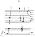
図2は、図1の実施例において影を低減できる理由を説明する断面図である。
【0058】
本実施例においても、図10及び図11で説明したように観察者の目40が斜めから画面を見た場合を考える。前面から入射した外光23は、白表示を行う領域の液晶層3を経由するためそのまま液晶表示パネルを通過した後、反射板8で反射し、反射光25となる。反射光25は、背面側の偏光板5で直線偏光になり、液晶層3のうちの黒表示を行う領域34を通過したあと、前面側の偏光板6で吸収されるため、図において点線で示したように反射光25は観察者の目40までは届かず、本来の黒表示領域31が表示される。
【0059】
一方、前面側から入射した外光24は黒表示を行う領域34の液晶層3を通過するため、背面側の偏光板5で吸収されて液晶表示パネルの裏側にも黒表示領域33が形成される。
【0060】
しかし、本実施例の場合、図11の時と異なり光拡散層は10、11の2箇所に配置されている。したがって、外光23は光拡散層11で散乱された後、散乱されず直進する光と散乱された光の両方ともさらに光拡散層10において拡散されるため、反射板8に届いた時には光拡散層10または光拡散層11の一方のみでは届かない場所まで光が十分に拡散されて届くこととなる。そして、その光が反射されて反射光27となり、再び光拡散層10、11の2箇所で拡散されることにより、今まで届かなかった光が観察者の目40に届くことになる。
【0061】
さらに、別の場所から入射する外光28についても、2つの光拡散層10、11により十分に拡散されることにより、光拡散層10または光拡散層11の一方のみでは届かない範囲まで十分に拡散されることにより反射光として観察者の目40まで届くこととなる。
【0062】
このように、2つの光拡散層10、11により十分に拡散することで、影32はほとんど目立たなくなる。
【0063】
また、反射板8でなく、光拡散層10に影が映る場合があったとしても、十分な拡散がなされることによりほとんど視認性には影響を及ぼさない。
【0064】
尚、光を十分に拡散するためには、光拡散層10、11と反射板8は互いに距離を離しておいた方が効果的である。そこで、本実施例においては、光拡散層11を第1の基板1と偏光板5との間に配置することにより、光拡散層10との間の距離を大きくしている。また、光拡散層10と反射板8との間に関しても導光体7があることにより両者の間の距離を大きくしている。
【0065】
また、本実施例においては、液晶表示パネルの背面側に少なくとも2つ以上の光拡散層10、11を設けることとし、液晶表示パネルの前面側には設けないことが望ましい。その理由は、液晶表示パネルの前面側に光拡散層を設けた場合、高精細化が進むと画像がぼやけてしまい、視認性が低下するからである。高精細の例としては例えば、1つのサブピクセルの大きさが縦200μm以下、横200/3μm以下であるような場合である。但し、画像のぼけが気にならなければさらに液晶表示パネルの前面側にも光拡散層を設けてかまわない。
【0066】
また、本実施例においては、斜めから見たときの影を目立たなくする効果があるため、例えば横電界方式などの広視野角(例えば視野角が150度以上の場合など)の液晶表示装置ではその効果が大きい。
【0067】
[第2の実施例]
図3は、本発明の第2の実施例を説明する断面図である。
【0068】
本実施例において、これまで説明した他の実施例と重複する点については説明を省略する。本実施例において図1の第1の実施例と異なる構成は、第1の基板1と偏光板5との間の光拡散層11に替えて、偏光板5の背面側(導光体7の位置する側)の表面に光拡散層12を配置した点である。
【0069】
光拡散層12としては、例えば、光拡散層として作用するAG付き偏光板を用いれば部材数が少なくて済む。尚、これに限られず、拡散粘着材、拡散板、拡散シート、拡散フィルムなどを用いてもかまわない。
【0070】
[第3の実施例]
図4は、本発明の第3の実施例を説明する断面図である。
【0071】
本実施例において、これまで説明した他の実施例と重複する点については説明を省略する。本実施例において図1の第1の実施例と異なる構成は、プリズムシート13を追加した点である。
【0072】
プリズムシート13の位置は、図4では偏光板5と光拡散層10の間に配置したが、これに限られず、光拡散層10と導光板7の間や、導光板7と反射板8の間としてもよい。プリズムシート13の数は1枚でも2枚以上でも良い。
【0073】
[第4の実施例]
図5は、本発明の第4の実施例を説明する断面図である。
【0074】
本実施例において、これまで説明した他の実施例と重複する点については説明を省略する。本実施例において図1の第1の実施例と異なる構成は、偏光板5の背面側に反射偏光板14を追加した点である。
【0075】
[第5の実施例]
図6は、本発明の第5の実施例を説明する断面図である。
【0076】
本実施例において、これまで説明した他の実施例と重複する点については説明を省略する。本実施例において図5の第4の実施例と異なる構成は、光拡散層15の位置である。すなわち、第1の基板1と偏光板5との間の光拡散層11に替えて、偏光板5と反射偏光板14との間に光拡散層15を配置した。
【0077】
光拡散層15としては、例えば光拡散層として作用する拡散粘着材を用い、偏光板5と反射偏光板14とを貼り合わせるようにすれば部材数が少なくて済む。尚、このような構成に限られず、他の光拡散層として作用する部材を用いても良い。
【0078】
[第6の実施例]
図7は、本発明の第6の実施例を説明する断面図である。
【0079】
本実施例において、これまで説明した他の実施例と重複する点については説明を省略する。本実施例において図5の第4の実施例と異なる構成は、光拡散層10、第1の基板1と偏光板5との間の光拡散層11に加え、偏光板5と反射偏光板14との間にも光拡散層15を配置した点である。
【0080】
光拡散層11、15として、例えば光拡散層として作用する拡散粘着材を用いれば部材数が少なくて済む。尚、このような構成に限られず、他の光拡散層として作用する部材を用いても良い。
【0081】
本実施例においてこれまでに説明した他の実施例と異なる構成は、第1の基板1と反射板8との間に配置された光拡散層が3層あることである。尚、3層に限られず、4層以上としても良い。光拡散層の数が多ければそれだけ拡散の効果は大きくなるが、光のロスの観点からは、なるべく数が少ない方が望ましい。
【0082】
[第7の実施例]
図8は、本発明の第7の実施例を説明する断面図である。
【0083】
本実施例において、これまで説明した他の実施例と重複する点については説明を省略する。本実施例において図7の第6の実施例と異なる構成は、光拡散層10を省略した点である。
【0084】
[その他の変形例]
これまで説明した実施例は、互いに矛盾しない限り2つ以上を相互に組み合わせることが可能である。例えば、図4の第3の実施例で説明したプリズムシート13を図5の第4の実施例に適用するなどである。
【0085】
【発明の効果】
これまで説明した本発明の実施例及び変形例によれば、良好な視認性を確保した液晶表示装置を得ることができる。
【図面の簡単な説明】
【図1】本発明の第1の実施例を説明する断面図である。
【図2】図1の実施例において影を低減できる理由を説明する断面図である。
【図3】本発明の第2の実施例を説明する断面図である。
【図4】本発明の第3の実施例を説明する断面図である。
【図5】本発明の第4の実施例を説明する断面図である。
【図6】本発明の第5の実施例を説明する断面図である。
【図7】本発明の第6の実施例を説明する断面図である。
【図8】本発明の第7の実施例を説明する断面図である。
【図9】従来の2番目の方式の液晶表示装置の一例を説明する断面図である。
【図10】従来の2番目の方式の液晶表示装置の画面を斜めから見たときの問題点を説明する斜視図である。
【図11】図10のような影が発生する理由を説明する断面図である。
【符号の説明】
1…第1の基板、2…第2の基板、3…液晶層、4…シール材、5,6…偏光板、7…導光体、8…反射板、9…光源、10,11,12,15…光拡散層、13…プリズムシート、14…反射偏光板、20…光源からの光、21,23,24,28…外光、22,25,26,27…反射光、30…表示領域、31,33,34…黒表示領域、32…影、40…観察者の目。[0001]
BACKGROUND OF THE INVENTION
The present invention relates to a liquid crystal display device, and more particularly to a liquid crystal display device capable of both transmissive display and reflective display using a transmissive liquid crystal display panel.
[0002]
[Prior art]
For example, in a liquid crystal display device used for a mobile phone or the like, a transmissive display is performed using light from a backlight in a dark environment, and a reflective display is performed using light from outside light in a bright environment. There is a liquid crystal display device capable of both transmissive display and reflective display.
[0003]
Liquid crystal display devices that enable both transmissive display and reflective display are roughly divided into the following two types.
[0004]
The first method is a transflective type (a case called a partially transmissive type) in which a translucent reflective film such as a half mirror or a reflective film provided with an opening for transmitting light from a backlight is built in a liquid crystal display panel. This is a combination of a liquid crystal display panel and a backlight.
[0005]
In the second method, the liquid crystal display panel itself is of a transmissive type, transmissive display using light from the light source of the backlight, and external light incident from the front side of the liquid crystal display panel is reflected by the reflector of the backlight. This is a method that enables reflection display to be used (see, for example,
[0006]
FIG. 9 is a cross-sectional view illustrating an example of a conventional second type liquid crystal display device.
This is a simplified illustration of the contents described in
[0007]
As shown in FIG. 9, a backlight is disposed on the back of a transmissive liquid crystal display panel (liquid crystal display element).
[0008]
In this liquid crystal display panel, a
[0009]
The backlight includes a light source 9, a
[0010]
The liquid crystal display panel is a transmissive liquid crystal display panel, and transmissive display is performed using
[0011]
Further, in this liquid crystal display device, a
[0012]
Moreover, in patent document 2, what stuck the resin film which disperse | distributed the scattering filler instead of the
[0013]
Moreover, in
[0014]
In
[0015]
[Patent Document 1]
JP 2002-98960 A (paragraphs 0033 to 0043, FIGS. 1 to 5)
[Patent Document 2]
JP 2002-98963 A (paragraphs 0044, 0060, 0130-0132, FIG. 1, FIG. 3, FIG. 5)
[Patent Document 3]
JP 2001-91943 A (paragraphs 0037, 0073 to 0076, 0087 to 0089, FIGS. 1 to 5)
[0016]
[Problems to be solved by the invention]
However, the inventors of the present application have found that the conventional liquid crystal display device has the following problems.
[0017]
FIG. 10 is a perspective view for explaining a problem when the screen of the second conventional liquid crystal display device is viewed obliquely.
[0018]
In the first conventional method, the light use efficiency is lowered during transmissive display using the light source of the backlight. Therefore, the second method is more advantageous when importance is attached to the transmittance.
[0019]
However, when the second method is adopted, when reflective display using external light is performed, when black is displayed on a part of the
[0020]
This phenomenon is considered to occur for the following reason.
[0021]
FIG. 11 is a cross-sectional view for explaining the reason why a shadow as shown in FIG. 10 occurs.
[0022]
Consider the case where the viewer's
[0023]
On the other hand, since the
[0024]
Although not shown, it is conceivable that a shadow is reflected not only on the reflecting
[0025]
In the case of the first conventional method, since a transflective liquid crystal display panel is used, it is considered that shadows can be produced by the same principle, but the reflection film incorporated before reaching the polarizing plate on the back surface. Since the reflection display is dominant, the shadow is hardly noticeable.
[0026]
The above description has been given by taking the case of the structure as in
[0027]
In
[0028]
Thus, conventionally, none of
[0029]
The present invention has been made based on such a background, and an object of the present invention is to obtain a liquid crystal display device that ensures good visibility.
[0030]
Other problems and objects of the present invention will become apparent from the entire specification.
[0031]
[Means for Solving the Problems]
Therefore, in the present invention, at least two or more light diffusion layers are provided between the
[0032]
Examples of typical configurations of the present invention are listed as follows.
[0033]
(1) a transmissive liquid crystal display panel that sandwiches a liquid crystal layer between a pair of substrates;
A backlight disposed on the back surface of the liquid crystal display panel and having a light source and a reflector;
A liquid crystal display device capable of transmissive display using light from the light source and reflective display using external light incident from the front side of the liquid crystal display panel reflected by the reflecting plate,
It is characterized by comprising at least two or more light diffusion layers disposed between the back substrate of the pair of substrates and the reflector of the backlight.
[0034]
(2) In (1), at least one of the light diffusion layers is a diffusion plate or a diffusion sheet.
[0035]
In (3), (1) or (2), at least one of the light diffusion layers is a diffusion adhesive material.
[0036]
(4) In any one of (1) to (3), at least one of the light diffusion layers is a diffusion film.
[0037]
(5) a transmissive liquid crystal display panel that sandwiches a liquid crystal layer between a pair of substrates;
A light source;
A light guide disposed on the back side of the liquid crystal display panel and receiving light from the light source;
A reflector disposed on the back surface of the light guide,
A liquid crystal display device capable of transmissive display using light from the light source and reflective display using external light incident from the front side of the liquid crystal display panel reflected by the reflecting plate,
It is characterized by comprising at least two or more light diffusion layers disposed between the rear substrate of the pair of substrates and the light guide.
[0038]
(6) In (5), a polarizing plate disposed between the rear substrate of the pair of substrates and the light guide,
The light diffusing layer is provided between the substrate on the back side and the polarizing plate.
[0039]
(7) In (5), a polarizing plate disposed between the rear substrate of the pair of substrates and the light guide,
It is provided with the diffusion adhesive material which is arrange | positioned between the said board | substrate of the said back side, and the said polarizing plate, and acts as the said light-diffusion layer.
[0040]
(8) In (5), a polarizing plate disposed between the rear substrate of the pair of substrates and the light guide,
And the light diffusion layer disposed on the surface of the polarizing plate on the side where the light guide is located.
[0041]
(9) In (5), an AG-attached polarizing plate is provided between the rear substrate of the pair of substrates and the light guide, and serves as a light diffusion layer. .
[0042]
(10) In (5), a polarizing plate disposed between the light guide and the back-side substrate of the pair of substrates,
A reflective polarizing plate disposed between the polarizing plate and the light guide;
A light diffusing layer disposed between the polarizing plate and the reflective polarizing plate is provided.
[0043]
(11) In (5), a polarizing plate disposed between the back substrate of the pair of substrates and the light guide;
A reflective polarizing plate disposed between the polarizing plate and the light guide;
A diffusion adhesive is provided between the polarizing plate and the reflective polarizing plate and functions as the light diffusion layer.
[0044]
(12) In (5), a polarizing plate disposed between the rear substrate of the pair of substrates and the light guide,
A reflective polarizing plate disposed between the polarizing plate and the light guide;
The light diffusion layer disposed between the back-side substrate and the polarizing plate;
The light diffusing layer is disposed between the polarizing plate and the reflective polarizing plate.
[0045]
(13) In any one of (5) to (12), with a diffusion plate or diffusion sheet that acts as one of the light diffusion layers,
The diffusion plate or the diffusion sheet is disposed at a position closest to the light guide plate among the at least two light diffusion layers.
[0046]
It should be noted that the present invention is not limited to the configurations listed above, and various modifications can be made without departing from the technical idea of the present invention.
[0047]
DETAILED DESCRIPTION OF THE INVENTION
Embodiments of the present invention will be described below with reference to the drawings.
[0048]
[First embodiment]
FIG. 1 is a sectional view for explaining a first embodiment of the present invention.
[0049]
In the liquid crystal display panel in this embodiment, a
[0050]
The liquid crystal display panel may be any system such as STN system, TN system, vertical electric field system, and horizontal electric field system as long as it is a transmissive liquid crystal display panel. An electrode (not shown) for driving the
[0051]
A backlight is disposed on the back surface of the liquid crystal display panel (the side opposite to the observer). In the present embodiment, as an example of a backlight, a light source 9, a
[0052]
In the present invention, as the functions necessary for the backlight, at least two functions of a light source used for transmissive display and a reflection function used for reflective display are required. 8. Any type of backlight may be used as long as it has these two functions. For example, a combination of a light source such as EL (electroluminescence) and a reflection function may be used.
[0053]
With such a configuration, not only the transmissive display is possible using the light 20 from the light source 9, but also the external light 21 from the front side of the liquid crystal display panel is reflected by the
[0054]
In this embodiment, not only the
[0055]
As the
[0056]
The light diffusion layers 10 and 11 can not only obtain a display with no uneven brightness, but also reduce the influence of the
[0057]
FIG. 2 is a sectional view for explaining the reason why the shadow can be reduced in the embodiment of FIG.
[0058]
Also in this embodiment, as described with reference to FIGS. 10 and 11, consider a case where the observer's
[0059]
On the other hand, since the
[0060]
However, in the case of the present embodiment, unlike the case of FIG. 11, the light diffusion layers are arranged at two
[0061]
Further, the
[0062]
In this way, the
[0063]
Further, even if a shadow is reflected on the
[0064]
In order to sufficiently diffuse light, it is more effective that the light diffusion layers 10 and 11 and the
[0065]
In this embodiment, it is preferable that at least two light diffusion layers 10 and 11 are provided on the back side of the liquid crystal display panel, and not provided on the front side of the liquid crystal display panel. The reason is that when a light diffusion layer is provided on the front side of the liquid crystal display panel, the image becomes blurred and the visibility is lowered as the definition becomes higher. As an example of high definition, for example, the size of one sub-pixel is 200 μm or less in length and 200/3 μm or less in width. However, a light diffusing layer may also be provided on the front side of the liquid crystal display panel if the image blur is not a concern.
[0066]
In addition, in this embodiment, since there is an effect of making the shadow inconspicuous when viewed from an oblique direction, a liquid crystal display device with a wide viewing angle (for example, when the viewing angle is 150 degrees or more) such as a horizontal electric field method is used. The effect is great.
[0067]
[Second Embodiment]
FIG. 3 is a sectional view for explaining a second embodiment of the present invention.
[0068]
In the present embodiment, the description of the points overlapping with the other embodiments described so far is omitted. In this embodiment, the configuration different from that of the first embodiment of FIG. 1 is that the
[0069]
As the
[0070]
[Third embodiment]
FIG. 4 is a sectional view for explaining a third embodiment of the present invention.
[0071]
In the present embodiment, the description of the points overlapping with the other embodiments described so far is omitted. In the present embodiment, a configuration different from the first embodiment of FIG. 1 is that a
[0072]
The position of the
[0073]
[Fourth embodiment]
FIG. 5 is a sectional view for explaining a fourth embodiment of the present invention.
[0074]
In the present embodiment, the description of the points overlapping with the other embodiments described so far is omitted. 1 is different from the first embodiment of FIG. 1 in that a reflective
[0075]
[Fifth embodiment]
FIG. 6 is a sectional view for explaining a fifth embodiment of the present invention.
[0076]
In the present embodiment, the description of the points overlapping with the other embodiments described so far is omitted. In this embodiment, the configuration different from the fourth embodiment of FIG. 5 is the position of the
[0077]
As the
[0078]
[Sixth embodiment]
FIG. 7 is a sectional view for explaining a sixth embodiment of the present invention.
[0079]
In the present embodiment, the description of the points overlapping with the other embodiments described so far is omitted. 5 differs from the fourth embodiment of FIG. 5 in addition to the
[0080]
If, for example, a diffusion adhesive material acting as a light diffusion layer is used as the light diffusion layers 11 and 15, the number of members can be reduced. In addition, it is not restricted to such a structure, You may use the member which acts as another light-diffusion layer.
[0081]
In the present embodiment, a different configuration from the other embodiments described so far is that there are three light diffusion layers disposed between the
[0082]
[Seventh embodiment]
FIG. 8 is a sectional view for explaining a seventh embodiment of the present invention.
[0083]
In the present embodiment, the description of the points overlapping with the other embodiments described so far is omitted. In the present embodiment, a configuration different from the sixth embodiment of FIG. 7 is that the
[0084]
[Other variations]
Two or more of the embodiments described so far can be combined with each other as long as they do not contradict each other. For example, the
[0085]
【The invention's effect】
According to the embodiments and modifications of the present invention described so far, it is possible to obtain a liquid crystal display device that ensures good visibility.
[Brief description of the drawings]
FIG. 1 is a cross-sectional view illustrating a first embodiment of the present invention.
FIG. 2 is a cross-sectional view illustrating the reason why shadows can be reduced in the embodiment of FIG.
FIG. 3 is a cross-sectional view illustrating a second embodiment of the present invention.
FIG. 4 is a sectional view for explaining a third embodiment of the present invention.
FIG. 5 is a cross-sectional view illustrating a fourth embodiment of the present invention.
FIG. 6 is a sectional view for explaining a fifth embodiment of the present invention.
FIG. 7 is a sectional view for explaining a sixth embodiment of the present invention.
FIG. 8 is a sectional view for explaining a seventh embodiment of the present invention.
FIG. 9 is a cross-sectional view illustrating an example of a conventional second type liquid crystal display device.
FIG. 10 is a perspective view for explaining a problem when the screen of the second conventional liquid crystal display device is viewed obliquely.
11 is a cross-sectional view for explaining the reason why a shadow as shown in FIG. 10 occurs.
[Explanation of symbols]
DESCRIPTION OF
Claims (27)
前記液晶表示パネルの背面に配置され、光源と反射板と導光体とを有するバックライトとを備え、
前記光源からの光を用いる透過表示と、前記液晶表示パネルの前面側から入射する外光を前記反射板で反射させて用いる反射表示とが可能な液晶表示装置であって、
前記一対の基板のうちの前記背面側の基板と前記バックライトとの間に配置され、所定の偏光方向の偏光を吸収する偏光板と、
前記一対の基板のうちの表面側の基板の外側に設けられるタッチパネルと、
前記一対の基板のうちの前記背面側の基板と前記バックライトの前記反射板との間に配置された少なくとも2つ以上の光拡散層とを備え、
前記少なくとも2つ以上の光拡散層は、第1の光拡散層と第2の光拡散層とを有し、
前記第1の光拡散層と前記第2の光拡散層との間にプリズムシートを有することを特徴とする液晶表示装置。A transmissive liquid crystal display panel that sandwiches a liquid crystal layer between a pair of substrates;
A backlight disposed on the back surface of the liquid crystal display panel, and having a light source, a reflector, and a light guide;
A liquid crystal display device capable of transmissive display using light from the light source and reflective display using external light incident from the front side of the liquid crystal display panel reflected by the reflecting plate,
A polarizing plate that is disposed between the back substrate of the pair of substrates and the backlight, and absorbs polarized light in a predetermined polarization direction;
A touch panel provided on the outside of the substrate on the surface side of the pair of substrates;
Of the pair of substrates, comprising at least two or more light diffusion layers disposed between the substrate on the back side and the reflector of the backlight,
The at least two or more light diffusion layers have a first light diffusion layer and a second light diffusion layer,
A liquid crystal display device comprising a prism sheet between the first light diffusion layer and the second light diffusion layer.
光源と、
前記液晶表示パネルの背面側に配置され前記光源からの光が入射される導光体と、
前記導光体の背面に配置された反射板とを備え、
前記光源からの光を用いる透過表示と、前記液晶表示パネルの前面側から入射する外光を前記反射板で反射させて用いる反射表示とが可能な液晶表示装置であって、
前記一対の基板のうちの前記背面側の基板と前記導光体との間に配置され、所定の偏光方向の偏光を吸収する偏光板と、
前記一対の基板のうちの表面側の基板の外側に設けられるタッチパネルと、
前記一対の基板のうちの前記背面側の基板と前記導光体との間に配置された少なくとも2つ以上の光拡散層とを備え、
前記少なくとも2つ以上の光拡散層は、第1の光拡散層と第2の光拡散層とを有し、
前記第1の光拡散層と前記第2の光拡散層との間にプリズムシートを有することを特徴とする液晶表示装置。A transmissive liquid crystal display panel that sandwiches a liquid crystal layer between a pair of substrates;
A light source;
A light guide disposed on the back side of the liquid crystal display panel and receiving light from the light source;
A reflector disposed on the back surface of the light guide,
A liquid crystal display device capable of transmissive display using light from the light source and reflective display using external light incident from the front side of the liquid crystal display panel reflected by the reflecting plate,
A polarizing plate that is disposed between the rear substrate of the pair of substrates and the light guide, and absorbs polarized light in a predetermined polarization direction;
A touch panel provided on the outside of the substrate on the surface side of the pair of substrates;
Of the pair of substrates, comprising at least two light diffusion layers disposed between the substrate on the back side and the light guide,
The at least two or more light diffusion layers have a first light diffusion layer and a second light diffusion layer,
A liquid crystal display device comprising a prism sheet between the first light diffusion layer and the second light diffusion layer.
光源と、
前記液晶表示パネルの背面側に配置され前記光源からの光が入射される導光体と、
前記導光体の背面に配置された反射板とを備え、
前記光源からの光を用いる透過表示と、前記液晶表示パネルの前面側から入射する外光を前記反射板で反射させて用いる反射表示とが可能な液晶表示装置であって、
前記一対の基板のうちの前記背面側の基板と前記導光体との間に配置され、所定の偏光方向の偏光を吸収する偏光板と、
前記一対の基板のうちの前記背面側の基板と前記導光体との間に配置された少なくとも2つ以上の光拡散層とを備え、
前記少なくとも2つ以上の光拡散層は、第1の光拡散層と第2の光拡散層とを有し、
前記第1の光拡散層と前記第2の光拡散層との間にプリズムシートを有し、
前記偏光板の前記導光体の位置する側の表面に配置された前記光拡散層を備えることを特徴とする液晶表示装置。A transmissive liquid crystal display panel that sandwiches a liquid crystal layer between a pair of substrates;
A light source;
A light guide disposed on the back side of the liquid crystal display panel and receiving light from the light source;
A reflector disposed on the back surface of the light guide,
A liquid crystal display device capable of transmissive display using light from the light source and reflective display using external light incident from the front side of the liquid crystal display panel reflected by the reflecting plate,
A polarizing plate that is disposed between the rear substrate of the pair of substrates and the light guide, and absorbs polarized light in a predetermined polarization direction;
Of the pair of substrates, comprising at least two light diffusion layers disposed between the substrate on the back side and the light guide,
The at least two or more light diffusion layers have a first light diffusion layer and a second light diffusion layer,
Having a prism sheet between the first light diffusion layer and the second light diffusion layer;
A liquid crystal display device comprising: the light diffusion layer disposed on a surface of the polarizing plate on a side where the light guide is located.
光源と、
前記液晶表示パネルの背面側に配置され前記光源からの光が入射される導光体と、
前記導光体の背面に配置された反射板とを備え、
前記光源からの光を用いる透過表示と、前記液晶表示パネルの前面側から入射する外光を前記反射板で反射させて用いる反射表示とが可能な液晶表示装置であって、
前記一対の基板のうちの前記背面側の基板と前記導光体との間に配置され、所定の偏光方向の偏光を吸収する偏光板と、
前記一対の基板のうちの前記背面側の基板と前記導光体との間に配置された少なくとも2つ以上の光拡散層とを備え、
前記少なくとも2つ以上の光拡散層は、第1の光拡散層と第2の光拡散層とを有し、
前記第1の光拡散層と前記第2の光拡散層との間にプリズムシートを有し、
前記偏光板と前記導光体との間に配置された反射偏光板と、
前記偏光板と前記反射偏光板との間に配置された光拡散層とを備えることを特徴とする液晶表示装置。A transmissive liquid crystal display panel that sandwiches a liquid crystal layer between a pair of substrates;
A light source;
A light guide disposed on the back side of the liquid crystal display panel and receiving light from the light source;
A reflector disposed on the back surface of the light guide,
A liquid crystal display device capable of transmissive display using light from the light source and reflective display using external light incident from the front side of the liquid crystal display panel reflected by the reflecting plate,
A polarizing plate disposed between the back-side substrate of the pair of substrates and the light guide, and absorbing polarized light in a predetermined polarization direction;
Of the pair of substrates, comprising at least two light diffusion layers disposed between the substrate on the back side and the light guide,
The at least two or more light diffusion layers have a first light diffusion layer and a second light diffusion layer,
Having a prism sheet between the first light diffusion layer and the second light diffusion layer;
A reflective polarizing plate disposed between the polarizing plate and the light guide;
A liquid crystal display device comprising: a light diffusion layer disposed between the polarizing plate and the reflective polarizing plate.
光源と、
前記液晶表示パネルの背面側に配置され前記光源からの光が入射される導光体と、
前記導光体の背面に配置された反射板とを備え、
前記光源からの光を用いる透過表示と、前記液晶表示パネルの前面側から入射する外光を前記反射板で反射させて用いる反射表示とが可能な液晶表示装置であって、
前記一対の基板のうちの前記背面側の基板と前記導光体との間に配置され、所定の偏光方向の偏光を吸収する偏光板と、
前記一対の基板のうちの前記背面側の基板と前記導光体との間に配置された少なくとも2つ以上の光拡散層とを備え、
前記少なくとも2つ以上の光拡散層は、第1の光拡散層と第2の光拡散層とを有し、
前記第1の光拡散層と前記第2の光拡散層との間にプリズムシートを有し、
前記偏光板と前記導光体との間に配置された反射偏光板と、
前記偏光板と前記反射偏光板との間に配置され前記光拡散層として作用する拡散粘着材とを備えることを特徴とする液晶表示装置。A transmissive liquid crystal display panel that sandwiches a liquid crystal layer between a pair of substrates;
A light source;
A light guide disposed on the back side of the liquid crystal display panel and receiving light from the light source;
A reflector disposed on the back surface of the light guide,
A liquid crystal display device capable of transmissive display using light from the light source and reflective display using external light incident from the front side of the liquid crystal display panel reflected by the reflecting plate,
A polarizing plate that is disposed between the rear substrate of the pair of substrates and the light guide, and absorbs polarized light in a predetermined polarization direction;
Of the pair of substrates, comprising at least two light diffusion layers disposed between the substrate on the back side and the light guide,
The at least two or more light diffusion layers have a first light diffusion layer and a second light diffusion layer,
Having a prism sheet between the first light diffusion layer and the second light diffusion layer;
A reflective polarizing plate disposed between the polarizing plate and the light guide;
A liquid crystal display device comprising: a diffusion adhesive disposed between the polarizing plate and the reflective polarizing plate and acting as the light diffusion layer.
前記背面側の基板と前記偏光板との間に配置された前記光拡散層と、
前記偏光板と前記反射偏光板との間に配置された前記光拡散層と、
前記反射偏光板と前記導光体との間に配置された前記プリズムシートと、
前記プリズムシートと前記導光体との間に配置された前記光拡散層とを備えることを特徴とする請求項5に記載の液晶表示装置。A reflective polarizing plate disposed between the polarizing plate and the light guide;
The light diffusion layer disposed between the back-side substrate and the polarizing plate;
The light diffusing layer disposed between the polarizing plate and the reflective polarizing plate;
The prism sheet disposed between the reflective polarizing plate and the light guide;
The liquid crystal display device according to claim 5, further comprising the light diffusion layer disposed between the prism sheet and the light guide.
前記拡散板または前記拡散シートは前記少なくとも2つ以上の光拡散層のうち最も前記導光体に近い位置に配置されていることを特徴とする請求項5から12の何れかに記載の液晶表示装置。With a diffusion plate or diffusion sheet that acts as one of the light diffusion layers,
The liquid crystal display according to claim 5, wherein the diffusion plate or the diffusion sheet is disposed at a position closest to the light guide body among the at least two light diffusion layers. apparatus.
前記液晶表示パネルの背面に配置され、光源と反射板と導光体とを有するバックライトとを備え、
前記光源からの光を用いる透過表示と、前記液晶表示パネルの前面側から入射する外光を前記反射板で反射させて用いる反射表示とが可能な液晶表示装置であって、
前記一対の基板のうちの前記背面側の基板と前記バックライトとの間に配置され、所定の偏光方向の偏光を吸収する偏光板と、
前記一対の基板のうちの表面側の基板の外側に設けられるタッチパネルと、
前記一対の基板のうちの前記背面側の基板と前記バックライトの前記反射板との間に配置された少なくとも2つ以上の光拡散層とを備え、
前記少なくとも2つ以上の光拡散層は、第1の光拡散層と第2の光拡散層とを有し、
前記第1の光拡散層と前記第2の光拡散層との間にプリズムシートと反射偏光板とを有することを特徴とする液晶表示装置。A transmissive liquid crystal display panel that sandwiches a liquid crystal layer between a pair of substrates;
A backlight disposed on the back surface of the liquid crystal display panel, and having a light source, a reflector, and a light guide;
A liquid crystal display device capable of transmissive display using light from the light source and reflective display using external light incident from the front side of the liquid crystal display panel reflected by the reflecting plate,
A polarizing plate that is disposed between the back substrate of the pair of substrates and the backlight, and absorbs polarized light in a predetermined polarization direction;
A touch panel provided on the outside of the substrate on the surface side of the pair of substrates;
Of the pair of substrates, comprising at least two or more light diffusion layers disposed between the substrate on the back side and the reflector of the backlight,
The at least two or more light diffusion layers have a first light diffusion layer and a second light diffusion layer,
A liquid crystal display device comprising a prism sheet and a reflective polarizing plate between the first light diffusion layer and the second light diffusion layer.
光源と、
前記液晶表示パネルの背面側に配置され前記光源からの光が入射される導光体と、
前記導光体の背面に配置された反射板とを備え、
前記光源からの光を用いる透過表示と、前記液晶表示パネルの前面側から入射する外光を前記反射板で反射させて用いる反射表示とが可能な液晶表示装置であって、
前記一対の基板のうちの前記背面側の基板と前記導光体との間に配置され、所定の偏光方向の偏光を吸収する偏光板と、
前記一対の基板のうちの表面側の基板の外側に設けられるタッチパネルと、
前記一対の基板のうちの前記背面側の基板と前記導光体との間に配置された少なくとも2つ以上の光拡散層とを備え、
前記少なくとも2つ以上の光拡散層は、第1の光拡散層と第2の光拡散層とを有し、
前記第1の光拡散層と前記第2の光拡散層との間にプリズムシートと反射偏光板とを有することを特徴とする液晶表示装置。A transmissive liquid crystal display panel that sandwiches a liquid crystal layer between a pair of substrates;
A light source;
A light guide disposed on the back side of the liquid crystal display panel and receiving light from the light source;
A reflector disposed on the back surface of the light guide,
A liquid crystal display device capable of transmissive display using light from the light source and reflective display using external light incident from the front side of the liquid crystal display panel reflected by the reflecting plate,
A polarizing plate that is disposed between the rear substrate of the pair of substrates and the light guide, and absorbs polarized light in a predetermined polarization direction;
A touch panel provided on the outside of the substrate on the surface side of the pair of substrates;
Of the pair of substrates, comprising at least two light diffusion layers disposed between the substrate on the back side and the light guide,
The at least two or more light diffusion layers have a first light diffusion layer and a second light diffusion layer,
A liquid crystal display device comprising a prism sheet and a reflective polarizing plate between the first light diffusion layer and the second light diffusion layer.
前記液晶表示パネルの背面に配置され、光源と反射板と導光体とを有するバックライトとを備え、
前記光源からの光を用いる透過表示と、前記液晶表示パネルの前面側から入射する外光を前記反射板で反射させて用いる反射表示とが可能な液晶表示装置であって、
前記一対の基板のうちの前記背面側の基板と前記バックライトとの間に配置され、所定の偏光方向の偏光を吸収する偏光板と、
前記一対の基板のうちの表面側の基板の外側に設けられるタッチパネルと、
前記一対の基板のうちの前記背面側の基板と前記バックライトの前記反射板との間に配置された少なくとも2つ以上の光拡散層とを備え、
前記少なくとも2つ以上の光拡散層は、第1の光拡散層と第2の光拡散層とを有し、
前記第1の光拡散層と前記第2の光拡散層との間にプリズムシートと前記偏光板とを有することを特徴とする液晶表示装置。A transmissive liquid crystal display panel that sandwiches a liquid crystal layer between a pair of substrates;
A backlight disposed on the back surface of the liquid crystal display panel, and having a light source, a reflector, and a light guide;
A liquid crystal display device capable of transmissive display using light from the light source and reflective display using external light incident from the front side of the liquid crystal display panel reflected by the reflecting plate,
A polarizing plate that is disposed between the back substrate of the pair of substrates and the backlight, and absorbs polarized light in a predetermined polarization direction;
A touch panel provided on the outside of the substrate on the surface side of the pair of substrates;
Of the pair of substrates, comprising at least two or more light diffusion layers disposed between the substrate on the back side and the reflector of the backlight,
The at least two or more light diffusion layers have a first light diffusion layer and a second light diffusion layer,
A liquid crystal display device comprising a prism sheet and the polarizing plate between the first light diffusion layer and the second light diffusion layer.
光源と、
前記液晶表示パネルの背面側に配置され前記光源からの光が入射される導光体と、
前記導光体の背面に配置された反射板とを備え、
前記光源からの光を用いる透過表示と、前記液晶表示パネルの前面側から入射する外光を前記反射板で反射させて用いる反射表示とが可能な液晶表示装置であって、
前記一対の基板のうちの表面側の基板の外側に設けられるタッチパネルと、
前記一対の基板のうちの前記背面側の基板と前記導光体との間に配置され、所定の偏光方向の偏光を吸収する偏光板と、
前記一対の基板のうちの前記背面側の基板と前記導光体との間に配置された少なくとも2つ以上の光拡散層とを備え、
前記少なくとも2つ以上の光拡散層は、第1の光拡散層と第2の光拡散層とを有し、
前記第1の光拡散層と前記第2の光拡散層との間にプリズムシートと前記偏光板とを有することを特徴とする液晶表示装置。A transmissive liquid crystal display panel that sandwiches a liquid crystal layer between a pair of substrates;
A light source;
A light guide disposed on the back side of the liquid crystal display panel and receiving light from the light source;
A reflector disposed on the back surface of the light guide,
A liquid crystal display device capable of transmissive display using light from the light source and reflective display using external light incident from the front side of the liquid crystal display panel reflected by the reflecting plate,
A touch panel provided on the outside of the substrate on the surface side of the pair of substrates;
A polarizing plate that is disposed between the rear substrate of the pair of substrates and the light guide, and absorbs polarized light in a predetermined polarization direction;
Of the pair of substrates, comprising at least two light diffusion layers disposed between the substrate on the back side and the light guide,
The at least two or more light diffusion layers have a first light diffusion layer and a second light diffusion layer,
A liquid crystal display device comprising a prism sheet and the polarizing plate between the first light diffusion layer and the second light diffusion layer.
Priority Applications (5)
| Application Number | Priority Date | Filing Date | Title |
|---|---|---|---|
| JP2002312032A JP4574942B2 (en) | 2002-10-28 | 2002-10-28 | Liquid crystal display |
| US10/662,405 US7443461B2 (en) | 2002-10-28 | 2003-09-16 | Liquid crystal display device having a prism sheet between first and second light diffusion layers |
| CNB2003101023799A CN1291269C (en) | 2002-10-28 | 2003-10-27 | Lcd |
| CNB2006101444147A CN100451765C (en) | 2002-10-28 | 2003-10-27 | Liquid crystal display device |
| US12/232,366 US20090027593A1 (en) | 2002-10-28 | 2008-09-16 | Liquid crystal display device having a prism sheet between first and second light diffusion |
Applications Claiming Priority (1)
| Application Number | Priority Date | Filing Date | Title |
|---|---|---|---|
| JP2002312032A JP4574942B2 (en) | 2002-10-28 | 2002-10-28 | Liquid crystal display |
Related Child Applications (1)
| Application Number | Title | Priority Date | Filing Date |
|---|---|---|---|
| JP2007190301A Division JP2007264677A (en) | 2007-07-23 | 2007-07-23 | Liquid crystal display device |
Publications (3)
| Publication Number | Publication Date |
|---|---|
| JP2004145155A JP2004145155A (en) | 2004-05-20 |
| JP2004145155A5 JP2004145155A5 (en) | 2005-09-02 |
| JP4574942B2 true JP4574942B2 (en) | 2010-11-04 |
Family
ID=32321594
Family Applications (1)
| Application Number | Title | Priority Date | Filing Date |
|---|---|---|---|
| JP2002312032A Expired - Lifetime JP4574942B2 (en) | 2002-10-28 | 2002-10-28 | Liquid crystal display |
Country Status (3)
| Country | Link |
|---|---|
| US (2) | US7443461B2 (en) |
| JP (1) | JP4574942B2 (en) |
| CN (2) | CN1291269C (en) |
Families Citing this family (11)
| Publication number | Priority date | Publication date | Assignee | Title |
|---|---|---|---|---|
| JP2005227708A (en) * | 2004-02-16 | 2005-08-25 | Toshiba Matsushita Display Technology Co Ltd | Liquid crystal display element |
| JP2006208534A (en) * | 2005-01-26 | 2006-08-10 | Sanyo Epson Imaging Devices Corp | Liquid crystal display device |
| DE102005047614A1 (en) * | 2005-10-05 | 2007-04-12 | Bayer Materialscience Ag | Light-scattering plastic composition with high brightness and its use in flat screens |
| US7733440B2 (en) * | 2006-06-02 | 2010-06-08 | Citizen Holdings Co., Ltd. | Liquid crystal display device |
| JP2009036879A (en) * | 2007-07-31 | 2009-02-19 | Casio Comput Co Ltd | Liquid crystal display element |
| KR101376245B1 (en) * | 2007-08-28 | 2014-03-21 | 엘지디스플레이 주식회사 | Backlight unit for liquid crystal display device |
| JP4569612B2 (en) * | 2007-09-06 | 2010-10-27 | ソニー株式会社 | Liquid crystal display |
| KR101625089B1 (en) * | 2009-02-19 | 2016-05-30 | 삼성전자주식회사 | Transflective display apparatus |
| KR101580994B1 (en) * | 2009-03-13 | 2016-01-12 | 삼성전자주식회사 | Transflective display apparatus |
| TWI481932B (en) * | 2012-06-26 | 2015-04-21 | Au Optronics Corp | Display device and display system combined thereof |
| KR20170019086A (en) * | 2015-08-11 | 2017-02-21 | 삼성전자주식회사 | A back light unit and a display apparatus |
Citations (5)
| Publication number | Priority date | Publication date | Assignee | Title |
|---|---|---|---|---|
| JP2000330107A (en) * | 1999-05-24 | 2000-11-30 | Nitto Denko Corp | Liquid crystal display device |
| JP2001083508A (en) * | 1999-09-14 | 2001-03-30 | Seiko Epson Corp | Display device and electronic instrument using the same |
| JP2002245825A (en) * | 2001-02-15 | 2002-08-30 | Nec Corp | Backlight, liquid crystal display device and electronic equipment |
| JP2002303728A (en) * | 2001-04-06 | 2002-10-18 | Nitto Denko Corp | Polarizing plate and method for manufacturing the same, adhesive for polarizing plate, optical film and liquid crystal display device both using the polarizing plate |
| JP2003015133A (en) * | 2001-04-27 | 2003-01-15 | Citizen Watch Co Ltd | Liquid crystal display device |
Family Cites Families (16)
| Publication number | Priority date | Publication date | Assignee | Title |
|---|---|---|---|---|
| US5418631A (en) * | 1993-05-14 | 1995-05-23 | Kaiser Optical Systems, Inc. | Edge-lit holographic diffusers for flat-panel displays |
| US6804058B1 (en) * | 1993-12-21 | 2004-10-12 | 3M Innovative Properties Company | Electroluminescent light source and display incorporating same |
| US5847795A (en) * | 1995-07-27 | 1998-12-08 | Canon Kabushiki Kaisha | Liquid crystal display apparatus and anti-reflection film applicable thereto |
| JP3233146B2 (en) * | 1996-08-23 | 2001-11-26 | セイコーエプソン株式会社 | Display element and electronic device using the same |
| WO1998052094A1 (en) * | 1997-05-14 | 1998-11-19 | Seiko Epson Corporation | Display and electronic device comprising the same |
| JP3460588B2 (en) * | 1997-09-18 | 2003-10-27 | セイコーエプソン株式会社 | Display device and electronic device using the same |
| JPH11212073A (en) * | 1998-01-26 | 1999-08-06 | Hitachi Ltd | Liquid crystal display device |
| JPH11316372A (en) * | 1998-04-30 | 1999-11-16 | Seiko Epson Corp | Liquid crystal device and electronic equipment |
| CA2339153C (en) * | 1998-07-31 | 2008-07-29 | Nippon Kayaku Kabushiki Kaisha | Reflectors and transflectors |
| US6630968B1 (en) * | 1999-02-01 | 2003-10-07 | Seiko Epson Corporation | Display device, electronic apparatus using the same, and light guider for display devices |
| JP2001091943A (en) | 1999-09-24 | 2001-04-06 | Casio Comput Co Ltd | Liquid crystal display device |
| JP4652527B2 (en) * | 2000-05-16 | 2011-03-16 | 株式会社きもと | Light diffusing sheet |
| JP4557389B2 (en) * | 2000-06-02 | 2010-10-06 | 大日本印刷株式会社 | Protective diffusion film, surface light source device and liquid crystal display device |
| JP3799981B2 (en) | 2000-09-26 | 2006-07-19 | カシオ計算機株式会社 | Liquid crystal display |
| JP2002098960A (en) | 2000-09-26 | 2002-04-05 | Casio Comput Co Ltd | Display device |
| US6827460B2 (en) * | 2001-08-03 | 2004-12-07 | Casio Computer Co., Ltd. | Lighting panel having light-collecting function and display device using same |
-
2002
- 2002-10-28 JP JP2002312032A patent/JP4574942B2/en not_active Expired - Lifetime
-
2003
- 2003-09-16 US US10/662,405 patent/US7443461B2/en not_active Expired - Fee Related
- 2003-10-27 CN CNB2003101023799A patent/CN1291269C/en not_active Expired - Lifetime
- 2003-10-27 CN CNB2006101444147A patent/CN100451765C/en not_active Expired - Lifetime
-
2008
- 2008-09-16 US US12/232,366 patent/US20090027593A1/en not_active Abandoned
Patent Citations (5)
| Publication number | Priority date | Publication date | Assignee | Title |
|---|---|---|---|---|
| JP2000330107A (en) * | 1999-05-24 | 2000-11-30 | Nitto Denko Corp | Liquid crystal display device |
| JP2001083508A (en) * | 1999-09-14 | 2001-03-30 | Seiko Epson Corp | Display device and electronic instrument using the same |
| JP2002245825A (en) * | 2001-02-15 | 2002-08-30 | Nec Corp | Backlight, liquid crystal display device and electronic equipment |
| JP2002303728A (en) * | 2001-04-06 | 2002-10-18 | Nitto Denko Corp | Polarizing plate and method for manufacturing the same, adhesive for polarizing plate, optical film and liquid crystal display device both using the polarizing plate |
| JP2003015133A (en) * | 2001-04-27 | 2003-01-15 | Citizen Watch Co Ltd | Liquid crystal display device |
Also Published As
| Publication number | Publication date |
|---|---|
| US20090027593A1 (en) | 2009-01-29 |
| CN100451765C (en) | 2009-01-14 |
| CN1499258A (en) | 2004-05-26 |
| JP2004145155A (en) | 2004-05-20 |
| CN1291269C (en) | 2006-12-20 |
| US7443461B2 (en) | 2008-10-28 |
| US20040100597A1 (en) | 2004-05-27 |
| CN1936672A (en) | 2007-03-28 |
Similar Documents
| Publication | Publication Date | Title |
|---|---|---|
| US10782466B2 (en) | Backlight module and display apparatus | |
| US10429679B2 (en) | Display device | |
| US20090027593A1 (en) | Liquid crystal display device having a prism sheet between first and second light diffusion | |
| TWI228196B (en) | Liquid crystal display device and electronic apparatus | |
| JP5195719B2 (en) | Liquid crystal display | |
| TWI338178B (en) | ||
| US20100283924A1 (en) | Stereoscopic Display Device | |
| US20210033913A1 (en) | Flexible liquid-crystal-screen module and method of assembling the same | |
| WO2010047144A1 (en) | Liquid crystal display apparatus | |
| US10302998B2 (en) | Image display device | |
| JP3226894U (en) | Backlight module | |
| JP2004253257A (en) | Planar lighting device | |
| JP5459728B2 (en) | Liquid crystal display | |
| CN108983447B (en) | Display device | |
| JP3873256B2 (en) | Surface lighting device | |
| JPH1114986A (en) | Illumination device, liquid crystal display device and electronic instrument | |
| JP2001166296A (en) | Liquid crystal display device | |
| US11327351B2 (en) | Display device including a light shielding layer covering a gap | |
| JP2007264677A (en) | Liquid crystal display device | |
| US20080191982A1 (en) | Display device | |
| JP3807944B2 (en) | Display device and lighting device | |
| JP2930387B2 (en) | Backlight device | |
| JP4813705B2 (en) | Liquid crystal display | |
| JP2000214446A (en) | Liquid crystal display device | |
| KR20110032575A (en) | The bendable type projection screens with non-glare and anti-reflective surface |
Legal Events
| Date | Code | Title | Description |
|---|---|---|---|
| A521 | Request for written amendment filed |
Free format text: JAPANESE INTERMEDIATE CODE: A523 Effective date: 20021028 |
|
| A521 | Request for written amendment filed |
Free format text: JAPANESE INTERMEDIATE CODE: A523 Effective date: 20050209 |
|
| A621 | Written request for application examination |
Free format text: JAPANESE INTERMEDIATE CODE: A621 Effective date: 20050209 |
|
| A521 | Request for written amendment filed |
Free format text: JAPANESE INTERMEDIATE CODE: A523 Effective date: 20050209 |
|
| RD02 | Notification of acceptance of power of attorney |
Free format text: JAPANESE INTERMEDIATE CODE: A7422 Effective date: 20060511 |
|
| RD04 | Notification of resignation of power of attorney |
Free format text: JAPANESE INTERMEDIATE CODE: A7424 Effective date: 20060511 |
|
| A977 | Report on retrieval |
Free format text: JAPANESE INTERMEDIATE CODE: A971007 Effective date: 20061204 |
|
| A131 | Notification of reasons for refusal |
Free format text: JAPANESE INTERMEDIATE CODE: A131 Effective date: 20070522 |
|
| A521 | Request for written amendment filed |
Free format text: JAPANESE INTERMEDIATE CODE: A523 Effective date: 20070723 |
|
| A131 | Notification of reasons for refusal |
Free format text: JAPANESE INTERMEDIATE CODE: A131 Effective date: 20081202 |
|
| A521 | Request for written amendment filed |
Free format text: JAPANESE INTERMEDIATE CODE: A523 Effective date: 20090130 |
|
| A521 | Request for written amendment filed |
Free format text: JAPANESE INTERMEDIATE CODE: A523 Effective date: 20090130 |
|
| A131 | Notification of reasons for refusal |
Free format text: JAPANESE INTERMEDIATE CODE: A131 Effective date: 20090609 |
|
| A521 | Request for written amendment filed |
Free format text: JAPANESE INTERMEDIATE CODE: A523 Effective date: 20090618 |
|
| RD02 | Notification of acceptance of power of attorney |
Free format text: JAPANESE INTERMEDIATE CODE: A7422 Effective date: 20100127 |
|
| RD04 | Notification of resignation of power of attorney |
Free format text: JAPANESE INTERMEDIATE CODE: A7424 Effective date: 20100225 |
|
| A131 | Notification of reasons for refusal |
Free format text: JAPANESE INTERMEDIATE CODE: A131 Effective date: 20100629 |
|
| A521 | Request for written amendment filed |
Free format text: JAPANESE INTERMEDIATE CODE: A523 Effective date: 20100709 |
|
| A521 | Request for written amendment filed |
Free format text: JAPANESE INTERMEDIATE CODE: A523 Effective date: 20100709 |
|
| TRDD | Decision of grant or rejection written | ||
| A01 | Written decision to grant a patent or to grant a registration (utility model) |
Free format text: JAPANESE INTERMEDIATE CODE: A01 Effective date: 20100817 |
|
| A01 | Written decision to grant a patent or to grant a registration (utility model) |
Free format text: JAPANESE INTERMEDIATE CODE: A01 |
|
| A61 | First payment of annual fees (during grant procedure) |
Free format text: JAPANESE INTERMEDIATE CODE: A61 Effective date: 20100819 |
|
| R150 | Certificate of patent or registration of utility model |
Ref document number: 4574942 Country of ref document: JP Free format text: JAPANESE INTERMEDIATE CODE: R150 Free format text: JAPANESE INTERMEDIATE CODE: R150 |
|
| FPAY | Renewal fee payment (event date is renewal date of database) |
Free format text: PAYMENT UNTIL: 20130827 Year of fee payment: 3 |
|
| FPAY | Renewal fee payment (event date is renewal date of database) |
Free format text: PAYMENT UNTIL: 20130827 Year of fee payment: 3 |
|
| S111 | Request for change of ownership or part of ownership |
Free format text: JAPANESE INTERMEDIATE CODE: R313121 Free format text: JAPANESE INTERMEDIATE CODE: R313115 |
|
| FPAY | Renewal fee payment (event date is renewal date of database) |
Free format text: PAYMENT UNTIL: 20130827 Year of fee payment: 3 |
|
| R350 | Written notification of registration of transfer |
Free format text: JAPANESE INTERMEDIATE CODE: R350 |
|
| R250 | Receipt of annual fees |
Free format text: JAPANESE INTERMEDIATE CODE: R250 |
|
| R250 | Receipt of annual fees |
Free format text: JAPANESE INTERMEDIATE CODE: R250 |
|
| R250 | Receipt of annual fees |
Free format text: JAPANESE INTERMEDIATE CODE: R250 |
|
| R250 | Receipt of annual fees |
Free format text: JAPANESE INTERMEDIATE CODE: R250 |
|
| R250 | Receipt of annual fees |
Free format text: JAPANESE INTERMEDIATE CODE: R250 |
|
| R250 | Receipt of annual fees |
Free format text: JAPANESE INTERMEDIATE CODE: R250 |
|
| R250 | Receipt of annual fees |
Free format text: JAPANESE INTERMEDIATE CODE: R250 |
|
| R250 | Receipt of annual fees |
Free format text: JAPANESE INTERMEDIATE CODE: R250 |
|
| S531 | Written request for registration of change of domicile |
Free format text: JAPANESE INTERMEDIATE CODE: R313531 |
|
| S533 | Written request for registration of change of name |
Free format text: JAPANESE INTERMEDIATE CODE: R313533 |
|
| R350 | Written notification of registration of transfer |
Free format text: JAPANESE INTERMEDIATE CODE: R350 |
|
| R250 | Receipt of annual fees |
Free format text: JAPANESE INTERMEDIATE CODE: R250 |
|
| R250 | Receipt of annual fees |
Free format text: JAPANESE INTERMEDIATE CODE: R250 |
|
| EXPY | Cancellation because of completion of term |