WO2010047144A1 - Liquid crystal display apparatus - Google Patents
Liquid crystal display apparatus Download PDFInfo
- Publication number
- WO2010047144A1 WO2010047144A1 PCT/JP2009/059846 JP2009059846W WO2010047144A1 WO 2010047144 A1 WO2010047144 A1 WO 2010047144A1 JP 2009059846 W JP2009059846 W JP 2009059846W WO 2010047144 A1 WO2010047144 A1 WO 2010047144A1
- Authority
- WO
- WIPO (PCT)
- Prior art keywords
- refractive index
- liquid crystal
- index layer
- high refractive
- crystal display
- Prior art date
Links
Images


Classifications
-
- G—PHYSICS
- G02—OPTICS
- G02B—OPTICAL ELEMENTS, SYSTEMS OR APPARATUS
- G02B3/00—Simple or compound lenses
- G02B3/0006—Arrays
- G02B3/0037—Arrays characterized by the distribution or form of lenses
- G02B3/005—Arrays characterized by the distribution or form of lenses arranged along a single direction only, e.g. lenticular sheets
-
- G—PHYSICS
- G02—OPTICS
- G02B—OPTICAL ELEMENTS, SYSTEMS OR APPARATUS
- G02B3/00—Simple or compound lenses
- G02B3/0006—Arrays
- G02B3/0037—Arrays characterized by the distribution or form of lenses
- G02B3/0056—Arrays characterized by the distribution or form of lenses arranged along two different directions in a plane, e.g. honeycomb arrangement of lenses
-
- G—PHYSICS
- G02—OPTICS
- G02F—OPTICAL DEVICES OR ARRANGEMENTS FOR THE CONTROL OF LIGHT BY MODIFICATION OF THE OPTICAL PROPERTIES OF THE MEDIA OF THE ELEMENTS INVOLVED THEREIN; NON-LINEAR OPTICS; FREQUENCY-CHANGING OF LIGHT; OPTICAL LOGIC ELEMENTS; OPTICAL ANALOGUE/DIGITAL CONVERTERS
- G02F1/00—Devices or arrangements for the control of the intensity, colour, phase, polarisation or direction of light arriving from an independent light source, e.g. switching, gating or modulating; Non-linear optics
- G02F1/01—Devices or arrangements for the control of the intensity, colour, phase, polarisation or direction of light arriving from an independent light source, e.g. switching, gating or modulating; Non-linear optics for the control of the intensity, phase, polarisation or colour
- G02F1/13—Devices or arrangements for the control of the intensity, colour, phase, polarisation or direction of light arriving from an independent light source, e.g. switching, gating or modulating; Non-linear optics for the control of the intensity, phase, polarisation or colour based on liquid crystals, e.g. single liquid crystal display cells
- G02F1/133—Constructional arrangements; Operation of liquid crystal cells; Circuit arrangements
- G02F1/1333—Constructional arrangements; Manufacturing methods
- G02F1/1335—Structural association of cells with optical devices, e.g. polarisers or reflectors
- G02F1/1336—Illuminating devices
- G02F1/133602—Direct backlight
- G02F1/133606—Direct backlight including a specially adapted diffusing, scattering or light controlling members
-
- G—PHYSICS
- G02—OPTICS
- G02F—OPTICAL DEVICES OR ARRANGEMENTS FOR THE CONTROL OF LIGHT BY MODIFICATION OF THE OPTICAL PROPERTIES OF THE MEDIA OF THE ELEMENTS INVOLVED THEREIN; NON-LINEAR OPTICS; FREQUENCY-CHANGING OF LIGHT; OPTICAL LOGIC ELEMENTS; OPTICAL ANALOGUE/DIGITAL CONVERTERS
- G02F1/00—Devices or arrangements for the control of the intensity, colour, phase, polarisation or direction of light arriving from an independent light source, e.g. switching, gating or modulating; Non-linear optics
- G02F1/01—Devices or arrangements for the control of the intensity, colour, phase, polarisation or direction of light arriving from an independent light source, e.g. switching, gating or modulating; Non-linear optics for the control of the intensity, phase, polarisation or colour
- G02F1/13—Devices or arrangements for the control of the intensity, colour, phase, polarisation or direction of light arriving from an independent light source, e.g. switching, gating or modulating; Non-linear optics for the control of the intensity, phase, polarisation or colour based on liquid crystals, e.g. single liquid crystal display cells
- G02F1/133—Constructional arrangements; Operation of liquid crystal cells; Circuit arrangements
- G02F1/1333—Constructional arrangements; Manufacturing methods
- G02F1/1335—Structural association of cells with optical devices, e.g. polarisers or reflectors
- G02F1/133504—Diffusing, scattering, diffracting elements
- G02F1/133507—Films for enhancing the luminance
-
- G—PHYSICS
- G02—OPTICS
- G02F—OPTICAL DEVICES OR ARRANGEMENTS FOR THE CONTROL OF LIGHT BY MODIFICATION OF THE OPTICAL PROPERTIES OF THE MEDIA OF THE ELEMENTS INVOLVED THEREIN; NON-LINEAR OPTICS; FREQUENCY-CHANGING OF LIGHT; OPTICAL LOGIC ELEMENTS; OPTICAL ANALOGUE/DIGITAL CONVERTERS
- G02F1/00—Devices or arrangements for the control of the intensity, colour, phase, polarisation or direction of light arriving from an independent light source, e.g. switching, gating or modulating; Non-linear optics
- G02F1/01—Devices or arrangements for the control of the intensity, colour, phase, polarisation or direction of light arriving from an independent light source, e.g. switching, gating or modulating; Non-linear optics for the control of the intensity, phase, polarisation or colour
- G02F1/13—Devices or arrangements for the control of the intensity, colour, phase, polarisation or direction of light arriving from an independent light source, e.g. switching, gating or modulating; Non-linear optics for the control of the intensity, phase, polarisation or colour based on liquid crystals, e.g. single liquid crystal display cells
- G02F1/133—Constructional arrangements; Operation of liquid crystal cells; Circuit arrangements
- G02F1/1333—Constructional arrangements; Manufacturing methods
- G02F1/1335—Structural association of cells with optical devices, e.g. polarisers or reflectors
- G02F1/1336—Illuminating devices
- G02F1/133602—Direct backlight
- G02F1/133606—Direct backlight including a specially adapted diffusing, scattering or light controlling members
- G02F1/133607—Direct backlight including a specially adapted diffusing, scattering or light controlling members the light controlling member including light directing or refracting elements, e.g. prisms or lenses
Definitions
- the present invention relates to a liquid crystal display device that displays information such as characters and images.
- liquid crystal display devices have been widely used in liquid crystal televisions, monitors, mobile phones and the like as flat panel displays having features such as thinness and light weight compared to conventional cathode ray tubes.
- a liquid crystal display device includes an illumination device (backlight) that emits light, and a liquid crystal panel that displays a desired image by acting as a shutter for light from a light source provided in the illumination device.
- a conventional liquid crystal display device includes a reflective polarizing plate that transmits only P-polarized light out of light from a light source in the lighting device, and the reflective polarized light.
- a diffusion sheet that modulates the P-polarized light from the plate by refractive index anisotropy and a phase difference plate that controls the phase difference so as to compensate the polarization component modulated by the diffusion sheet with linearly polarized light are provided.
- this conventional liquid crystal display device after the P-polarized light component that has passed through the retardation plate is condensed by the prism sheet, light is incident on the liquid crystal panel through a polarizing plate whose axis is aligned with the P-polarized light.
- the incident efficiency of light to the liquid crystal panel is improved and high luminance display is possible.
- the information displayed on the liquid crystal panel has a problem that the contrast is lowered and the display quality is also lowered.
- incident light incident on the liquid crystal panel is incident at various angles with respect to the normal direction on the display surface of the liquid crystal panel.
- a conventional liquid crystal display device for example, when black display is performed in line units, light from a place where black display is not performed is emitted to the outside from a display line performing black display. In some cases, the luminance of the black display line increases, and the contrast decreases.
- an anti-glare treatment antireflection treatment
- incident light to the liquid crystal panel is random on the polarizing plate surface.
- an object of the present invention is to provide a liquid crystal display device excellent in display quality capable of preventing a decrease in contrast.
- a liquid crystal display device is attached to a pair of substrates such that a liquid crystal layer, a pair of substrates sandwiching the liquid crystal layer, and the pair of substrates are sandwiched therebetween.
- a liquid crystal display device including a liquid crystal panel having a pair of polarizing plates, and an illumination device that is provided on one side of the pair of polarizing plates and emits illumination light to the liquid crystal panel,
- a low refractive index layer having a low refractive index below a predetermined refractive index, and a lens having a higher refractive index than that of the low refractive index layer and a high refractive index layer provided integrally with the low refractive index layer With seats,
- the low refractive index layer is attached to the polarizing plate in a state of being in close contact with the polarizing plate provided on the lighting device side of the pair of polarizing plates. is there.
- the low refractive index layer and the high refractive index layer are integrally provided in the lens sheet, and the low refractive index layer is in close contact with the polarizing plate on the lighting device side.
- the inventors of the present invention have found that by attaching a lens sheet to the polarizing plate, the light from the illumination device can be incident in the normal direction on the display surface of the liquid crystal panel. That is, the inventor of the present invention provides the low-refractive-index layer and the high-refractive-index layer integrally so that the light from the illumination device is transmitted to the normal line at the interface between the low-refractive-index layer and the high-refractive-index layer. Acquired that the direction can be aligned.
- the high refractive index layer may include a prism sheet having a plurality of triangular stripes arranged in a predetermined direction.
- light from the illumination device can be reliably aligned in the normal direction at the interface between the plurality of triangular prism sheets and the low refractive index layer.
- the high refractive index layer may include a lenticular lens sheet having a plurality of convex lenses arranged in a predetermined direction.
- the light from the illumination device can be reliably aligned in the normal direction at the interface between the lenticular lens sheet having a plurality of convex lenses and the low refractive index layer.
- the high refractive index layer includes a plurality of convexly formed lenses.
- the plurality of convexly formed lenses are included in the high refractive index layer, the light from the illumination device can be reliably aligned in the normal direction while enhancing the light condensing performance.
- a light incident layer having a refractive index lower than that of the high refractive index layer is integrally provided on the high refractive index layer on the lighting device side of the high refractive index layer. It is preferable that
- the light incident layer is provided integrally with the high refractive index layer on the illumination device side of the high refractive index layer, the light from the illumination device can be easily incident on the high refractive index layer.
- the light utilization efficiency of the lighting device can be easily improved.
- FIG. 1 is a schematic cross-sectional view illustrating a liquid crystal display device according to a first embodiment of the present invention.
- 2A and 2B are a perspective view and a side view of the high refractive index layer shown in FIG. 1, respectively.
- FIG. 3 is a schematic cross-sectional view illustrating a liquid crystal display device according to the second embodiment of the present invention.
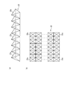
- 4 (a) and 4 (b) are a partial perspective view and a plan view of the high refractive index layer shown in FIG. 3, respectively.
- FIG. 5 is a schematic cross-sectional view illustrating a liquid crystal display device according to a third embodiment of the present invention.
- FIG. 6 is a perspective view of the high refractive index layer shown in FIG.
- FIG. 7 is a schematic cross-sectional view for explaining a liquid crystal display device according to a fourth embodiment of the present invention.
- FIGS. 8A and 8B are a partial perspective view and a side view of the high refractive index layer shown in FIG. 7,
- FIG. 1 is a schematic cross-sectional view illustrating a liquid crystal display device according to a first embodiment of the present invention.
- a liquid crystal display device 1 of the present embodiment is configured by using the display element of the present invention, and a liquid crystal panel 2 in which the upper side of FIG. 1 is installed as a viewing side (display surface side), and a liquid crystal panel 2 is provided on the non-display surface side (lower side in FIG. 1), and an illuminating device 3 that generates illumination light for illuminating the liquid crystal panel 2 is provided.
- the liquid crystal panel 2 includes a CF (Color Filter) substrate 4 and an array substrate 5 constituting a pair of substrates, a liquid crystal layer 6 sandwiched between the CF substrate 4 and the array substrate 5, and the CF substrate 4 and the array substrate 5 Are provided on the outer surfaces of the CF substrate 4 and the array substrate 5, respectively.
- the lens sheet 10 of the present embodiment is integrally provided on the polarizing plate 8 on the lighting device 3 side, and the illumination light from the lighting device 3 is applied on the display surface of the liquid crystal panel 2. They are arranged in the line direction (vertical direction in FIG. 1) (details will be described later).
- the CF substrate 4 and the array substrate 5 are made of a transparent synthetic resin such as a flat glass material or acrylic resin.
- pixel electrodes, TFTs (Thin Film Transistors), and the like are formed between the liquid crystal layer 6 (not shown) according to a plurality of pixels included in the display surface of the liquid crystal panel 2.
- a color filter, a counter electrode, and the like are formed on the CF substrate 4 between the liquid crystal layer 6 (not shown).
- the liquid crystal mode and pixel structure of the liquid crystal panel 2 are arbitrary. Moreover, the drive mode of the liquid crystal panel 2 is also arbitrary. That is, as the liquid crystal panel 2, any liquid crystal panel that can display information can be used. Therefore, the detailed structure of the liquid crystal panel 2 is not shown in FIG.
- the polarizing plate 7 is provided with, for example, a PVA (polyvinyl alcohol) film 7b having predetermined polarization characteristics, and TAC (triacetyl cellulose) films 7a and 7c provided so as to sandwich the PVA film 7b.
- the TAC film 7 c is attached to the surface of the CF substrate 4.
- an antireflection film 9 containing beads or the like is integrally bonded as a surface treatment film on the display surface side of the TAC film 7a.
- the polarizing plate 8 is provided with, for example, a PVA film 8b having predetermined polarization characteristics, and TAC films 8a and 8c provided so as to sandwich the PVA film 8b.
- the TAC film 8 a is attached to the surface of the array substrate 5.
- the lens sheet 10 is integrally bonded to the non-display surface side of the TAC film 8c.
- polarizing plates 7 and 8 are bonded to the corresponding CF substrate 4 or array substrate 5 so as to cover at least the effective display area of the display surface provided in the liquid crystal panel 2.
- a retardation plate can be used instead of the TAC films 7c and 8a.
- the lighting device 3 is provided with a plurality of cold cathode fluorescent tubes (CCFL) 14 and a bottomed chassis 15 that accommodates these cold cathode fluorescent tubes 14.
- CCFL cold cathode fluorescent tubes
- a reflection sheet 16 is installed on the inner surface of the chassis 15, and the light utilization efficiency of the cold cathode fluorescent tube 14 is improved by reflecting light from the cold cathode fluorescent tube 14 as a light source to the liquid crystal panel 2 side. It is designed to improve.
- a diffusion plate 17 is installed in the opening of the chassis 15 so as to close the opening.
- Each cold cathode fluorescent tube 14 has a straight tube shape, and electrode portions (not shown) provided at both ends thereof are supported outside the chassis 15.
- each cold cathode fluorescent tube 14 is made of a small tube having a diameter of about 3.0 to 4.0 mm and excellent in luminous efficiency, so that the lighting device 3 having a compact and excellent luminous efficiency can be easily obtained. It can be configured.
- Each cold cathode fluorescent tube 14 is held inside the chassis 15 in a state where the distance between the reflection sheet 16 and the diffusion plate 17 is kept at a predetermined distance by a light source holder (not shown).
- the diffusion plate 17 is made of, for example, a rectangular synthetic resin or glass material having a thickness of about 2 mm.
- the light from the cold cathode fluorescent tube 14 is configured to enter the lens sheet 10 through the diffusion plate 17.
- an optical sheet such as a prism (light collecting) sheet for increasing the luminance may be installed between the lens sheet 10 and the diffusion plate 17.
- a drive circuit 18 for driving the liquid crystal panel 2 and an inverter circuit 19 for lighting a plurality of cold cathode fluorescent tubes 14 at high frequency by inverter drive are installed.
- the configuration using the direct illumination device 3 has been described.
- the present embodiment is not limited to this, and an edge light illumination device having a light guide plate may be used.
- the illuminating device which has other light sources, such as hot cathode fluorescent tubes other than a cold cathode fluorescent tube, and LED, can also be used.
- lens sheet 10 of the present embodiment will be specifically described with reference to FIG.
- 2 (a) and 2 (b) are a perspective view and a side view of the high refractive index layer shown in FIG. 1, respectively.
- the lens sheet 10 includes a low refractive index layer 11 having a low refractive index equal to or lower than a predetermined refractive index, a high refractive index layer 12 having a higher refractive index than the low refractive index layer 11, and A light incident layer 13 having a lower refractive index than the high refractive index layer 12 is provided.
- the low refractive index layer 11 is made of a transparent synthetic resin (for example, polycarbonate resin, polystyrene resin, or polypropylene resin) having a refractive index of 1.0 to 1.6.
- the high refractive index layer 12 is made of the transparent synthetic resin having a refractive index greater than 1.4 and not greater than 2.0.
- the light incident layer 13 is made of the transparent synthetic resin having a refractive index of 1.0 to 1.6.
- the low refractive index layer 11 and the high refractive index layer 12 are integrally provided, and the high refractive index layer 12 and the light incident layer 13 are integrally provided.
- the high refractive index layer 12 is configured using, for example, a prism sheet having a triangular cross section protruding toward the liquid crystal panel 2, and further, the low refractive index layer 11 is disposed on the lighting device 3 side.
- the polarizing plate 8 is attached to the polarizing plate 8 in close contact with the polarizing plate 8.
- the high refractive index layer 12 includes a prism sheet having a plurality of triangular stripes arranged in a predetermined direction (a direction perpendicular to the paper surface of FIG. 1). Specifically, as illustrated in FIG. 2, the high refractive index layer 12 includes a triangular prism 12a and a prism groove 12b provided between the prism surfaces 12a1 of two adjacent prisms 12a. Each of the plurality of prisms 12a constitutes the triangular strip.
- the normal direction on the display surface of the liquid crystal panel 2 (shown as “H” in FIG. 2B). ) Is formed to have a predetermined angle ⁇ 1 and a predetermined angle ⁇ 2. As these specific angle ranges, values in the range of 35 ° to 55 ° are both selected.
- the high refractive index layer 12 is attached to the liquid crystal panel 2 side via the low refractive index layer 11, and emits light from the illumination device 3 incident from the light incident layer 13 to the liquid crystal panel 2 side. ing.
- angles ⁇ 1 and ⁇ 2 at the apex of the prism 12a of the high refractive index layer 12 are configured such that light from the illumination device 3 incident from the light incident layer 13 can be aligned as light parallel to the normal direction H.
- these angles ⁇ 1 and ⁇ 2 may be the same angle or different angles as long as they are values within the above range.
- the lens sheet 10 in which the low refractive index layer 11 and the high refractive index layer 12 are integrally provided is installed. Further, in the lens sheet 10, the low refractive index layer 11 is attached to the polarizing plate 8 in a state of being in close contact with the polarizing plate 8 on the lighting device 3 side. As a result, in the liquid crystal display device 1 of the present embodiment, the light from the illumination device 3 is applied to the display surface of the liquid crystal panel 2 at the interface between the low refractive index layer 11 and the high refractive index layer 12 in the lens sheet 10. Can be aligned in the line direction.
- the lens sheet 10 can make the light incident on the liquid crystal panel 2 with the light from the illumination device 3 aligned in the normal direction.
- the antireflection film 9 including beads is provided on the polarizing plate 7 on the display surface side of the liquid crystal panel 2, unlike the conventional example, the contrast is reduced.
- the liquid crystal display device 1 excellent in display quality that can be prevented can be configured.
- the light from the illumination device 3 is reliably aligned in the normal direction at the interface between the low refractive index layer 11 and the high refractive index layer 12 including the prism sheet. Can do.
- FIG. 3 is a schematic cross-sectional view for explaining a liquid crystal display device according to a second embodiment of the present invention.
- FIG. 4 (a) and FIG. 4 (b) are portions of the high refractive index layer shown in FIG. It is a perspective view and a top view.
- the main difference between the present embodiment and the first embodiment is that a plurality of quadrangular pyramid lenses are included in the high refractive index layer instead of the prism sheet. Is a point.
- symbol is attached
- the lens sheet 20 of the present embodiment has a low refractive index layer 21 having a low refractive index equal to or lower than a predetermined refractive index, and a higher refractive index than the low refractive index layer 21. And a light incident layer 13 having a lower refractive index than that of the high refractive index layer 22.
- the low refractive index layer 21, the high refractive index layer 22, and the light incident layer 13 are configured by using a transparent synthetic resin as in the first embodiment, and are further integrated in this order. Provided.
- the high refractive index layer 22 includes a plurality of quadrangular pyramid lenses 22a as illustrated in FIG. That is, in the high refractive index layer 22, as illustrated in FIG. 4B, a plurality of quadrangular pyramid-shaped lenses are provided along directions parallel to the vertical direction and the horizontal direction on the display surface of the liquid crystal panel 2. 22a is arranged. Further, these lenses 22a are formed on the light incident layer 13, and are attached to the liquid crystal panel 2 side through the low refractive index layer 21 as in the first embodiment. . In the lens sheet 20, the light from the illumination device 3 incident from the light incident layer 13 is aligned in the normal direction at the interface between the low refractive index layer 11 and the high refractive index layer 12 and the liquid crystal panel 2 side. The light is emitted.
- the present embodiment can achieve the same operations and effects as the first embodiment. Further, in the present embodiment, since a plurality of quadrangular pyramid lenses 22a are included in the high refractive index layer 22, illumination is performed in a direction perpendicular to the paper surface of FIG. 3 as compared to the first embodiment. Light from the device 3 can be collected. That is, in this embodiment, it is possible to reliably align the light in the normal direction while improving the light condensing property of the illumination device 3 as compared with the first embodiment.
- a configuration using a triangular pyramid lens may be used.
- FIG. 5 is a schematic cross-sectional view illustrating a liquid crystal display device according to a third embodiment of the present invention
- FIG. 6 is a perspective view of the high refractive index layer shown in FIG.
- the main difference between the present embodiment and the first embodiment is that a lenticular lens sheet is included in the high refractive index layer instead of the prism sheet.
- symbol is attached
- the lens sheet 30 of the present embodiment has a low refractive index layer 31 having a low refractive index equal to or lower than a predetermined refractive index, and a higher refractive index than the low refractive index layer 31.
- the high refractive index layer 32 having light and the light incident layer 13 having a refractive index lower than that of the high refractive index layer 32 are provided.
- the low refractive index layer 31, the high refractive index layer 32, and the light incident layer 13 are configured using a transparent synthetic resin, as in the first embodiment, and are further integrated in this order. Provided.
- the high refractive index layer 32 includes a lenticular lens sheet having a plurality of convex lenses arranged in a predetermined direction (a direction perpendicular to the paper surface of FIG. 5). More specifically, as illustrated in FIG. 6, the high refractive index layer 32 includes a lens 32a having a semicircular cross section and a lens groove 32b provided between the lens surfaces 32a1 of two adjacent lenses 32a. Each of the plurality of lenses 32a constitutes the convex lens. Furthermore, the high refractive index layer 32 is attached to the liquid crystal panel 2 side via the low refractive index layer 31 as in the first embodiment.
- the light from the illumination device 3 incident from the light incident layer 13 is aligned in the normal direction at the interface between the low refractive index layer 31 and the high refractive index layer 32, and the liquid crystal panel 2 side is aligned. The light is emitted.
- the present embodiment can achieve the same operations and effects as the first embodiment. Further, in the liquid crystal display device 1 of the present embodiment, the light from the illumination device 3 is reliably aligned in the normal direction at the interface between the low refractive index layer 31 and the high refractive index layer 32 including the lenticular lens sheet. be able to.
- FIG. 7 is a schematic cross-sectional view illustrating a liquid crystal display device according to a fourth embodiment of the present invention.
- FIGS. 8A and 8B are partial perspective views of the high refractive index layer shown in FIG. It is a figure and a side view.
- the main difference between the present embodiment and the third embodiment is that a plurality of hemispherical lenses are included in the high refractive index layer instead of the lenticular lens sheet.
- symbol is attached
- the low refractive index layer 41, the high refractive index layer 42, and the light incident layer 13 are configured using a transparent synthetic resin, as in the third embodiment, and are further integrated in this order. Provided.
- the high refractive index layer 42 includes a plurality of hemispherical lenses 42a. That is, in the high refractive index layer 42, as illustrated in FIG. 8B, a plurality of hemispherical lenses 42a are provided along directions parallel to the vertical direction and the horizontal direction on the display surface of the liquid crystal panel 2, respectively. Is arranged. Further, these lenses 42a are formed on the light incident layer 13, and are attached to the liquid crystal panel 2 side through the low refractive index layer 41 as in the third embodiment. .
- the light from the illumination device 3 incident from the light incident layer 13 is aligned in the normal direction at the interface between the low refractive index layer 41 and the high refractive index layer 42, and the liquid crystal panel 2 side. The light is emitted.
- the present embodiment can achieve the same operations and effects as the third embodiment. Further, in the present embodiment, since the plurality of hemispherical lenses 42a are included in the high refractive index layer 42, the illumination device is more perpendicular to the paper surface of FIG. 7 than in the third embodiment. The light from 3 can be collected. That is, in the present embodiment, it is possible to reliably align the light in the normal direction while improving the light condensing property of the illumination device 3 as compared with the third embodiment.
- a configuration using a substantially hemispherical lens having an elliptical bottom surface may be used.
- the liquid crystal display device of the present invention is not limited to this, and other types such as a transflective type, a reflective type, etc. It can be applied to the liquid crystal display device.
- the present invention is provided integrally with the low refractive index layer and the high refractive index layer.
- the lens sheet is provided and the low refractive index layer is attached to the polarizing plate in close contact with the polarizing plate provided on the lighting device side.
- the light incident layer is provided integrally with the high refractive index layer as in each of the above embodiments, the light from the illumination device can be easily incident on the high refractive index layer. This is preferable in that the light utilization efficiency of the apparatus can be easily improved.
- a high refractive index layer is configured by providing a plurality of quadrangular pyramid and hemispherical lenses on the light incident layer.
- the lens only needs to include a plurality of lenses formed in a convex shape in the high refractive index layer.
- a flat substrate formed using the same material as the lens, and formed on this substrate A high refractive index layer having a plurality of lenses can also be used.
- the present invention is useful for a liquid crystal display device with excellent display quality that can prevent a decrease in contrast.
Abstract
Description
所定の屈折率以下の低い屈折率を有する低屈折率層、及び前記低屈折率層よりも高い屈折率を有するとともに、前記低屈折率層に一体的に設けられた高屈折率層を有するレンズシートを備え、
前記レンズシートでは、前記低屈折率層が前記一対の偏光板のうち、前記照明装置側に設けられた偏光板に密着した状態で、当該偏光板に取り付けられていることを特徴とするものである。 In order to achieve the above object, a liquid crystal display device according to the present invention is attached to a pair of substrates such that a liquid crystal layer, a pair of substrates sandwiching the liquid crystal layer, and the pair of substrates are sandwiched therebetween. A liquid crystal display device including a liquid crystal panel having a pair of polarizing plates, and an illumination device that is provided on one side of the pair of polarizing plates and emits illumination light to the liquid crystal panel,
A low refractive index layer having a low refractive index below a predetermined refractive index, and a lens having a higher refractive index than that of the low refractive index layer and a high refractive index layer provided integrally with the low refractive index layer With seats,
In the lens sheet, the low refractive index layer is attached to the polarizing plate in a state of being in close contact with the polarizing plate provided on the lighting device side of the pair of polarizing plates. is there.
図1は、本発明の第1の実施形態にかかる液晶表示装置を説明する概略断面図である。図1において、本実施形態の液晶表示装置1は、本発明の表示素子を用いて構成されるとともに、図1の上側が視認側(表示面側)として設置される液晶パネル2と、液晶パネル2の非表示面側(図1の下側)に配置されて、当該液晶パネル2を照明する照明光を発生する照明装置3とが設けられている。 [First Embodiment]
FIG. 1 is a schematic cross-sectional view illustrating a liquid crystal display device according to a first embodiment of the present invention. In FIG. 1, a liquid crystal display device 1 of the present embodiment is configured by using the display element of the present invention, and a liquid crystal panel 2 in which the upper side of FIG. 1 is installed as a viewing side (display surface side), and a liquid crystal panel 2 is provided on the non-display surface side (lower side in FIG. 1), and an
図3は本発明の第2の実施形態にかかる液晶表示装置を説明する概略断面図であり、図4は(a)及び図4(b)はそれぞれ図3に示した高屈折率層の部分斜視図及び平面図である。図において、本実施形態と上記第1の実施形態との主な相違点は、プリズムシートに代えて、複数の四角錐状のレンズが高屈折率層に含まれている点である。点である。なお、上記第1の実施形態と共通する要素については、同じ符号を付して、その重複した説明を省略する。 [Second Embodiment]
FIG. 3 is a schematic cross-sectional view for explaining a liquid crystal display device according to a second embodiment of the present invention. FIG. 4 (a) and FIG. 4 (b) are portions of the high refractive index layer shown in FIG. It is a perspective view and a top view. In the figure, the main difference between the present embodiment and the first embodiment is that a plurality of quadrangular pyramid lenses are included in the high refractive index layer instead of the prism sheet. Is a point. In addition, about the element which is common in the said 1st Embodiment, the same code | symbol is attached | subjected and the duplicate description is abbreviate | omitted.
図5は本発明の第3の実施形態にかかる液晶表示装置を説明する概略断面図であり、図6は図5に示した高屈折率層の斜視図である。図において、本実施形態と上記第1の実施形態との主な相違点は、プリズムシートに代えて、レンチキュラーレンズシートが高屈折率層に含まれている点である。なお、上記第1の実施形態と共通する要素については、同じ符号を付して、その重複した説明を省略する。 [Third Embodiment]
FIG. 5 is a schematic cross-sectional view illustrating a liquid crystal display device according to a third embodiment of the present invention, and FIG. 6 is a perspective view of the high refractive index layer shown in FIG. In the figure, the main difference between the present embodiment and the first embodiment is that a lenticular lens sheet is included in the high refractive index layer instead of the prism sheet. In addition, about the element which is common in the said 1st Embodiment, the same code | symbol is attached | subjected and the duplicate description is abbreviate | omitted.
図7は本発明の第4の実施形態にかかる液晶表示装置を説明する概略断面図であり、図8(a)及び図8(b)はそれぞれ図7に示した高屈折率層の部分斜視図及び側面図である。図において、本実施形態と上記第3の実施形態との主な相違点は、レンチキュラーレンズシートに代えて、複数の半球状のレンズが高屈折率層に含まれている点である。なお、上記第3の実施形態と共通する要素については、同じ符号を付して、その重複した説明を省略する。 [Fourth Embodiment]
FIG. 7 is a schematic cross-sectional view illustrating a liquid crystal display device according to a fourth embodiment of the present invention. FIGS. 8A and 8B are partial perspective views of the high refractive index layer shown in FIG. It is a figure and a side view. In the figure, the main difference between the present embodiment and the third embodiment is that a plurality of hemispherical lenses are included in the high refractive index layer instead of the lenticular lens sheet. In addition, about the element which is common in the said 3rd Embodiment, the same code | symbol is attached | subjected and the duplicate description is abbreviate | omitted.
2 液晶パネル
3 照明装置
4 CF基板(一対の基板)
5 アレイ基板(一対の基板)
6 液晶層
7、8 偏光板
10、20、30、40 レンズシート
11、21、31、41 低屈折率層
12、22、32、42 高屈折率層
22a、42a レンズ
13 光入射層 DESCRIPTION OF SYMBOLS 1 Liquid crystal display device 2
5 Array substrates (a pair of substrates)
6
Claims (5)
- 液晶層と、前記液晶層を狭持する一対の基板と、前記一対の基板を挟むように、当該一対の基板に取り付けられた一対の偏光板とを有する液晶パネル、及び前記一対の偏光板の一方側に設けられて、前記液晶パネルに照明光を出射する照明装置を備えた液晶表示装置であって、
所定の屈折率以下の低い屈折率を有する低屈折率層、及び前記低屈折率層よりも高い屈折率を有するとともに、前記低屈折率層に一体的に設けられた高屈折率層を有するレンズシートを備え、
前記レンズシートでは、前記低屈折率層が前記一対の偏光板のうち、前記照明装置側に設けられた偏光板に密着した状態で、当該偏光板に取り付けられている、
ことを特徴とする液晶表示装置。 A liquid crystal panel having a liquid crystal layer, a pair of substrates sandwiching the liquid crystal layer, and a pair of polarizing plates attached to the pair of substrates so as to sandwich the pair of substrates, and the pair of polarizing plates A liquid crystal display device provided with an illumination device provided on one side and emitting illumination light to the liquid crystal panel,
A low refractive index layer having a low refractive index below a predetermined refractive index, and a lens having a higher refractive index than that of the low refractive index layer and a high refractive index layer provided integrally with the low refractive index layer With seats,
In the lens sheet, the low refractive index layer is attached to the polarizing plate in a state of being in close contact with the polarizing plate provided on the lighting device side among the pair of polarizing plates.
A liquid crystal display device. - 前記高屈折率層には、所定の方向に配列された複数の三角条を有するプリズムシートが含まれている請求項1に記載の液晶表示装置。 The liquid crystal display device according to claim 1, wherein the high refractive index layer includes a prism sheet having a plurality of triangular stripes arranged in a predetermined direction.
- 前記高屈折率層には、所定の方向に配列された複数の凸レンズを有するレンチキュラーレンズシートが含まれている請求項1に記載の液晶表示装置。 The liquid crystal display device according to claim 1, wherein the high refractive index layer includes a lenticular lens sheet having a plurality of convex lenses arranged in a predetermined direction.
- 前記高屈折率層には、凸状に形成されたレンズが複数含まれている請求項1に記載の液晶表示装置。 The liquid crystal display device according to claim 1, wherein the high refractive index layer includes a plurality of convexly formed lenses.
- 前記レンズシートでは、前記高屈折率層よりも低い屈折率を有する光入射層が前記高屈折率層の前記照明装置側で当該高屈折率層に一体的に設けられている請求項1~4のいずれか1項に記載の液晶表示装置。 In the lens sheet, a light incident layer having a refractive index lower than that of the high refractive index layer is integrally provided on the high refractive index layer on the lighting device side of the high refractive index layer. The liquid crystal display device according to any one of the above.
Priority Applications (2)
| Application Number | Priority Date | Filing Date | Title |
|---|---|---|---|
| US13/122,562 US20110187966A1 (en) | 2008-10-24 | 2009-05-29 | Liquid crystal display device |
| CN2009801397044A CN102171603A (en) | 2008-10-24 | 2009-05-29 | Liquid crystal display apparatus |
Applications Claiming Priority (2)
| Application Number | Priority Date | Filing Date | Title |
|---|---|---|---|
| JP2008-274507 | 2008-10-24 | ||
| JP2008274507 | 2008-10-24 |
Publications (1)
| Publication Number | Publication Date |
|---|---|
| WO2010047144A1 true WO2010047144A1 (en) | 2010-04-29 |
Family
ID=42119194
Family Applications (1)
| Application Number | Title | Priority Date | Filing Date |
|---|---|---|---|
| PCT/JP2009/059846 WO2010047144A1 (en) | 2008-10-24 | 2009-05-29 | Liquid crystal display apparatus |
Country Status (3)
| Country | Link |
|---|---|
| US (1) | US20110187966A1 (en) |
| CN (1) | CN102171603A (en) |
| WO (1) | WO2010047144A1 (en) |
Cited By (1)
| Publication number | Priority date | Publication date | Assignee | Title |
|---|---|---|---|---|
| JP2015200832A (en) * | 2014-04-09 | 2015-11-12 | 富士フイルム株式会社 | Brightness enhancement film, polarizing plate and image display device |
Families Citing this family (6)
| Publication number | Priority date | Publication date | Assignee | Title |
|---|---|---|---|---|
| JP6870907B2 (en) * | 2014-03-31 | 2021-05-12 | 日東電工株式会社 | Optical member, polarizing plate set and liquid crystal display device |
| JP2015200866A (en) * | 2014-03-31 | 2015-11-12 | 日東電工株式会社 | Optical member, polarizing plate set and liquid crystal display apparatus |
| KR101712287B1 (en) | 2015-10-30 | 2017-03-06 | 엘지디스플레이 주식회사 | Liquid Crystal Display And Method For Manufacturing Of The Same |
| US10223952B2 (en) | 2016-10-26 | 2019-03-05 | Microsoft Technology Licensing, Llc | Curved edge display with controlled distortion |
| US10185064B2 (en) * | 2016-10-26 | 2019-01-22 | Microsoft Technology Licensing, Llc | Curved edge display with controlled luminance |
| CN110824770A (en) * | 2019-11-07 | 2020-02-21 | 宁波视睿迪光电有限公司 | Backlight module |
Citations (3)
| Publication number | Priority date | Publication date | Assignee | Title |
|---|---|---|---|---|
| JPH07318709A (en) * | 1994-05-27 | 1995-12-08 | Sekisui Chem Co Ltd | Light control sheet |
| JPH09146093A (en) * | 1995-11-24 | 1997-06-06 | Hitachi Ltd | Illumination device and liquid crystal display device using it |
| JP2008003243A (en) * | 2006-06-21 | 2008-01-10 | Fujifilm Corp | Optical sheet, light source device, and display device |
Family Cites Families (1)
| Publication number | Priority date | Publication date | Assignee | Title |
|---|---|---|---|---|
| US7719636B2 (en) * | 2007-03-14 | 2010-05-18 | Lg Electronics Inc. | Optical sheet and liquid crystal display using the same |
-
2009
- 2009-05-29 CN CN2009801397044A patent/CN102171603A/en active Pending
- 2009-05-29 WO PCT/JP2009/059846 patent/WO2010047144A1/en active Application Filing
- 2009-05-29 US US13/122,562 patent/US20110187966A1/en not_active Abandoned
Patent Citations (3)
| Publication number | Priority date | Publication date | Assignee | Title |
|---|---|---|---|---|
| JPH07318709A (en) * | 1994-05-27 | 1995-12-08 | Sekisui Chem Co Ltd | Light control sheet |
| JPH09146093A (en) * | 1995-11-24 | 1997-06-06 | Hitachi Ltd | Illumination device and liquid crystal display device using it |
| JP2008003243A (en) * | 2006-06-21 | 2008-01-10 | Fujifilm Corp | Optical sheet, light source device, and display device |
Cited By (1)
| Publication number | Priority date | Publication date | Assignee | Title |
|---|---|---|---|---|
| JP2015200832A (en) * | 2014-04-09 | 2015-11-12 | 富士フイルム株式会社 | Brightness enhancement film, polarizing plate and image display device |
Also Published As
| Publication number | Publication date |
|---|---|
| CN102171603A (en) | 2011-08-31 |
| US20110187966A1 (en) | 2011-08-04 |
Similar Documents
| Publication | Publication Date | Title |
|---|---|---|
| KR101005466B1 (en) | Transparent see-through display device | |
| US8035775B2 (en) | Polarization control system and display device | |
| EP1839084B1 (en) | Liquid crystal display device and mobile station having the same | |
| WO2010047144A1 (en) | Liquid crystal display apparatus | |
| US8427606B2 (en) | Liquid crystal display comprising a reflective polarizing layer including a plurality of microfibers each having an anisotropic refractive index and longitudinally extending in the same direction | |
| US9477117B2 (en) | Optical lens module and backlight unit | |
| KR20140052819A (en) | Liquid crystal display device having backlight unit to be able to control viewing angle | |
| JPWO2008155878A1 (en) | Liquid crystal display | |
| WO2009141953A1 (en) | Liquid crystal display device | |
| US20060109395A1 (en) | Area light source device and liquid crystal display device including the same | |
| WO2007142438A1 (en) | Multilayer film, backlight unit and liquid crystal display having the same | |
| KR101740194B1 (en) | Display panel unit and display device | |
| JPH10268306A (en) | Liquid crystal display device | |
| JP2009059498A (en) | Lighting device and liquid crystal display device | |
| KR20060075221A (en) | Liquid crystal display device and mobile station having the same | |
| US20070047111A1 (en) | Prism sheet and backlight unit employed in a liquid crystal display | |
| JP2004145155A (en) | Liquid crystal display | |
| CN109212817B (en) | Wide viewing angle display device | |
| US20110037923A1 (en) | Light condensing film, backlight module and liquid crystal display | |
| JP2005221639A (en) | Liquid crystal device and projection display device | |
| KR101264725B1 (en) | Display Device | |
| JP2009271379A (en) | Transmission type display device | |
| KR101380056B1 (en) | Liquid crystal display | |
| KR101782642B1 (en) | Liquid Crystal Display | |
| JP4354840B2 (en) | Liquid crystal display |
Legal Events
| Date | Code | Title | Description |
|---|---|---|---|
| WWE | Wipo information: entry into national phase |
Ref document number: 200980139704.4 Country of ref document: CN |
|
| 121 | Ep: the epo has been informed by wipo that ep was designated in this application |
Ref document number: 09821844 Country of ref document: EP Kind code of ref document: A1 |
|
| WWE | Wipo information: entry into national phase |
Ref document number: 13122562 Country of ref document: US |
|
| NENP | Non-entry into the national phase |
Ref country code: DE |
|
| 122 | Ep: pct application non-entry in european phase |
Ref document number: 09821844 Country of ref document: EP Kind code of ref document: A1 |
|
| NENP | Non-entry into the national phase |
Ref country code: JP |