JP4574675B2 - Communication management system - Google Patents
Communication management system Download PDFInfo
- Publication number
- JP4574675B2 JP4574675B2 JP2007513543A JP2007513543A JP4574675B2 JP 4574675 B2 JP4574675 B2 JP 4574675B2 JP 2007513543 A JP2007513543 A JP 2007513543A JP 2007513543 A JP2007513543 A JP 2007513543A JP 4574675 B2 JP4574675 B2 JP 4574675B2
- Authority
- JP
- Japan
- Prior art keywords
- data
- communication
- communication control
- database
- communication data
- Prior art date
- Legal status (The legal status is an assumption and is not a legal conclusion. Google has not performed a legal analysis and makes no representation as to the accuracy of the status listed.)
- Expired - Fee Related
Links
Images


Classifications
-
- H—ELECTRICITY
- H04—ELECTRIC COMMUNICATION TECHNIQUE
- H04L—TRANSMISSION OF DIGITAL INFORMATION, e.g. TELEGRAPHIC COMMUNICATION
- H04L63/00—Network architectures or network communication protocols for network security
- H04L63/02—Network architectures or network communication protocols for network security for separating internal from external traffic, e.g. firewalls
- H04L63/0227—Filtering policies
- H04L63/0263—Rule management
-
- H—ELECTRICITY
- H04—ELECTRIC COMMUNICATION TECHNIQUE
- H04L—TRANSMISSION OF DIGITAL INFORMATION, e.g. TELEGRAPHIC COMMUNICATION
- H04L63/00—Network architectures or network communication protocols for network security
- H04L63/14—Network architectures or network communication protocols for network security for detecting or protecting against malicious traffic
- H04L63/1408—Network architectures or network communication protocols for network security for detecting or protecting against malicious traffic by monitoring network traffic
- H04L63/1416—Event detection, e.g. attack signature detection
-
- H—ELECTRICITY
- H04—ELECTRIC COMMUNICATION TECHNIQUE
- H04L—TRANSMISSION OF DIGITAL INFORMATION, e.g. TELEGRAPHIC COMMUNICATION
- H04L2101/00—Indexing scheme associated with group H04L61/00
- H04L2101/30—Types of network names
- H04L2101/345—Types of network names containing wildcard characters
-
- H—ELECTRICITY
- H04—ELECTRIC COMMUNICATION TECHNIQUE
- H04L—TRANSMISSION OF DIGITAL INFORMATION, e.g. TELEGRAPHIC COMMUNICATION
- H04L2463/00—Additional details relating to network architectures or network communication protocols for network security covered by H04L63/00
- H04L2463/144—Detection or countermeasures against botnets
-
- H—ELECTRICITY
- H04—ELECTRIC COMMUNICATION TECHNIQUE
- H04L—TRANSMISSION OF DIGITAL INFORMATION, e.g. TELEGRAPHIC COMMUNICATION
- H04L43/00—Arrangements for monitoring or testing data switching networks
- H04L43/08—Monitoring or testing based on specific metrics, e.g. QoS, energy consumption or environmental parameters
- H04L43/0805—Monitoring or testing based on specific metrics, e.g. QoS, energy consumption or environmental parameters by checking availability
- H04L43/0817—Monitoring or testing based on specific metrics, e.g. QoS, energy consumption or environmental parameters by checking availability by checking functioning
-
- H—ELECTRICITY
- H04—ELECTRIC COMMUNICATION TECHNIQUE
- H04L—TRANSMISSION OF DIGITAL INFORMATION, e.g. TELEGRAPHIC COMMUNICATION
- H04L61/00—Network arrangements, protocols or services for addressing or naming
- H04L61/30—Managing network names, e.g. use of aliases or nicknames
Description
本発明は、通信管理技術に関し、特に、不適切な通信を管理する通信管理システム及び通信管理方法に関する。 The present invention relates to a communication management technique, and more particularly to a communication management system and a communication management method for managing inappropriate communication.
インターネットのインフラが整備され、携帯電話端末、パーソナルコンピュータ、VoIP(Voice over Internet Protocol)電話端末などの通信端末が広く普及した現在、インターネットの利用者は爆発的に増加している。このような状況下、コンピュータウイルス、ハッキング、スパムメールなど、セキュリティに関する問題が顕在化しており、通信を適切に制御する技術が求められている。通信環境の向上に伴って通信量も膨大になっており、大容量のデータを高速に処理する通信制御装置の必要性が増している。
近年、感染したコンピュータに被害を与えたり、悪用してスパムメール送信やDDoS攻撃の踏み台にすることを主目的とした悪質なプログラム(malware)が出現し、問題となっている。このような悪質なプログラムは「ボット(bot)」と呼ばれ、外部からの命令にしたがって動作するので、感染したコンピュータは、ボットを介して外部から自由に操作することができてしまう。しかも、同じボットが多数のコンピュータに感染している場合、1回の命令で多数のコンピュータを同時に操作することができるため、場合によっては甚大な被害が出る虞がある。 In recent years, malicious programs (malware), whose main purpose is to cause damage to infected computers or to be used as a springboard for spam mail transmission or DDoS attacks, have become a problem. Such a malicious program is called a “bot” and operates according to a command from the outside, so that an infected computer can be freely operated from the outside through the bot. In addition, when the same bot is infected with a large number of computers, a large number of computers can be operated at the same time with a single command, and there is a possibility that serious damage may occur in some cases.
ボットは、次々に新しい変種が作られるのでウイルス対策ソフトなどによる検知が困難である。さらに、攻撃者がボットを操作する命令として、独自のプロトコルを使うことが可能であることが、ボットの検出をより困難にしている。 Bots are difficult to detect with anti-virus software because new variants are created one after another. Furthermore, the ability of an attacker to use a unique protocol as a command to manipulate the bot makes it more difficult to detect the bot.
本発明はこうした状況に鑑みてなされたものであり、その目的は、不適切な通信を管理する技術の提供にある。 The present invention has been made in view of such a situation, and an object thereof is to provide a technique for managing inappropriate communication.
本発明のある態様は、通信管理システムに関する。この通信管理システムは、通信データの中から、特定の通信データを抽出するためのルールを格納したルールデータベースと、通信データを取得し、その通信データが前記ルールデータベースに格納されたルールに合致するか否かを検索する検索部と、前記ルールデータベースに格納されたルールに合致する通信データを検知したときに、その通信データを出力する出力部と、を備えることを特徴とする。 One embodiment of the present invention relates to a communication management system. This communication management system acquires a rule database storing rules for extracting specific communication data from communication data, and the communication data, and the communication data matches the rules stored in the rule database. A search unit for searching whether or not, and an output unit for outputting the communication data when the communication data matching the rule stored in the rule database is detected.
通信管理システムは、上流のネットワークから通信データを取得して前記検索部へ供給する第1の通信制御部と、前記通信データを下流のネットワークへ送出する第2の通信制御部と、を更に備えてもよく、前記出力部は、前記ルールに合致する通信データを複製して出力してもよい。 The communication management system further includes a first communication control unit that acquires communication data from an upstream network and supplies the communication data to the search unit, and a second communication control unit that sends the communication data to a downstream network. The output unit may copy and output communication data that matches the rule.
通信管理システムは、前記ルールデータベースに格納されたルールの変更を受け付ける更新部を更に備えてもよい。通信管理システムは、前記更新部が受け付けた前記ルールの変更を前記ルールデータベースにリアルタイムに反映させるデータベースサーバを更に備えてもよい。 The communication management system may further include an update unit that accepts a change of the rule stored in the rule database. The communication management system may further include a database server that reflects the change of the rule received by the update unit in the rule database in real time.
検索部は、FPGA(Field Programmable Gate Array)やワイヤードロジック回路により構成されてもよい。 The search unit may be configured by an FPGA (Field Programmable Gate Array) or a wired logic circuit.
本発明の別の態様は、通信管理方法に関する。この通信管理方法は、通信データを取得し、その通信データが、通信データの中から特定の通信データを抽出するためのルールを格納したルールデータベースに格納されたルールに合致するか否かを検索するステップと、前記ルールデータベースに格納されたルールに合致する通信データを検知したときに、その通信データを出力するステップと、を含むことを特徴とする。 Another aspect of the present invention relates to a communication management method. This communication management method acquires communication data, and searches whether the communication data matches a rule stored in a rule database storing a rule for extracting specific communication data from the communication data. And a step of outputting the communication data when the communication data matching the rule stored in the rule database is detected.
なお、以上の構成要素の任意の組合せ、本発明の表現を方法、装置、システム、記録媒体、コンピュータプログラムなどの間で変換したものもまた、本発明の態様として有効である。 It should be noted that any combination of the above-described constituent elements and a conversion of the expression of the present invention between a method, an apparatus, a system, a recording medium, a computer program, etc. are also effective as an aspect of the present invention.
本発明によれば、不適切な通信を管理する技術を提供することができる。 According to the present invention, it is possible to provide a technique for managing inappropriate communication.
10 通信制御装置、20 パケット処理回路、30 検索回路、32 位置検出回路、33 比較回路、34 インデックス回路、35 比較回路、36 バイナリサーチ回路、36A,36B,36C 比較回路、36Z 制御回路、40 処理実行回路、50 第1データベース、60 第2データベース、100 通信制御システム、110 運用監視サーバ、120 接続管理サーバ、130 メッセージ出力サーバ、140 ログ管理サーバ、150 データベースサーバ、200 通信経路制御装置、300 通信管理システム、310 ユーザ端末、320 ボット、322 ボットネット、332 正常シグネチャリスト、334 異常シグネチャリスト、336 ルールデータベース、340 運用者端末、342 警告取得部、344 通信データ取得部、346 解析部、348 判定結果取得部、352 正常シグネチャリスト更新部、354 異常シグネチャリスト更新部、356 ルールデータベース更新部、362 正常シグネチャリスト、364 異常シグネチャリスト、366 ルールデータベース、390 インターネット。 10 communication control device, 20 packet processing circuit, 30 search circuit, 32 position detection circuit, 33 comparison circuit, 34 index circuit, 35 comparison circuit, 36 binary search circuit, 36A, 36B, 36C comparison circuit, 36Z control circuit, 40 processing Execution circuit, 50 first database, 60 second database, 100 communication control system, 110 operation monitoring server, 120 connection management server, 130 message output server, 140 log management server, 150 database server, 200 communication path control device, 300 communication Management system, 310 user terminal, 320 bot, 322 botnet, 332 normal signature list, 334 abnormal signature list, 336 rule database, 340 operator terminal, 342 warning acquisition unit, 344 Data acquisition unit, 346 analysis unit, 348 determination result acquisition unit, 352 normal signature list update unit, 354 abnormal signature list update unit, 356 rule database update unit, 362 normal signature list, 364 abnormal signature list, 366 rule database, 390 Internet .
まず、前提技術として、CPU及びOSを有さず、専用のハードウェア回路によりパケットフィルタリング機能を実現する通信制御システムについて説明する。つづいて、実施の形態として、前提技術の通信制御システムを利用してボットネットにおける通信を管理する技術について説明する。 First, as a prerequisite technology, a communication control system that does not have a CPU and an OS and realizes a packet filtering function with a dedicated hardware circuit will be described. Next, as an embodiment, a technique for managing communication in a botnet using the communication control system of the base technology will be described.
(前提技術)
図1は、前提技術に係る通信制御システムの構成を示す。通信制御システム100は、通信制御装置10と、通信制御装置10の動作を支援するために設けられた各種の周辺装置を含む。前提技術の通信制御装置10は、インターネットサービスプロバイダなどにより提供されるパケットフィルタリング機能を実現する。ネットワークの経路に設けられた通信制御装置10は、ネットワークを介して送受信されるパケットを取得して、その内容を解析し、通信の許否を判断する。通信が許可される場合は、通信制御装置10は、そのパケットをネットワークへ送出する。通信が禁止される場合は、通信制御装置10は、そのパケットを破棄し、必要であれば送信元に対して警告メッセージなどを返信する。(Prerequisite technology)
FIG. 1 shows a configuration of a communication control system according to the base technology. The
前提技術の通信制御システム100では、複数の通信制御装置10a、10b、10c、・・・、が設けられており、それらを協働させて、1台の通信制御装置10として機能させているが、以下、個々の通信制御装置10a、10b、10c、・・・も、それらの総称も区別せずに通信制御装置10と呼ぶ。
In the
本前提技術の通信制御システム100では、それぞれの通信制御装置10は、パケットの処理に必要なデータベースの少なくとも一部を分割して保持しているが、分割して保持するのに必要な台数よりも少なくとも1台以上余分に設けられる。例えば、1台あたり10万件のデータを保持できるとすると、データ数が30万件以上40万件未満である場合、運用に必要な通信制御装置の台数は4台であるが、いずれかの通信制御装置10が故障したときに代わって運用させるための待機用として、また、通信制御装置10に含まれるデータベースを更新するときの待機用として、1台以上の通信制御装置10を設け、合計で最低5台の通信制御装置10を設ける。従来は、フォールトトレラントのために、システム全体を二重化させる必要があったが、本前提技術の技術によれば、分割された単位の通信制御装置10を余分に設けておけばよいので、コストを低減することができる。これら複数の通信制御装置10a、10b、10c、・・・、の運用状況は、運用監視サーバ110により管理される。本前提技術の運用監視サーバ110は、通信制御装置の運用状況を管理するための管理テーブルを有する。
In the
周辺装置は、運用監視サーバ110、接続管理サーバ120、メッセージ出力サーバ130、ログ管理サーバ140、及びデータベースサーバ150を含む。接続管理サーバ120は、通信制御装置10に対する接続を管理する。接続管理サーバ120は、例えば、携帯電話端末から送出されたパケットを通信制御装置10で処理する際に、パケットに含まれる携帯電話端末を一意に識別する情報を用いて、通信制御システム100のサービスを享受可能なユーザであることを認証する。いったん認証されると、その携帯電話端末に一時的に付されたIPアドレスから送出されたパケットは、一定の期間は接続管理サーバ120で認証せずに通信制御装置10へ送られて処理される。メッセージ出力サーバ130は、通信制御装置10により判定された通信の許否の結果に応じて、パケットの送信先又は送信元に対するメッセージを出力する。ログ管理サーバ140は、通信制御装置10の運用履歴を管理する。データベースサーバ150は、外部から最新のデータベースを取得し、通信制御装置10に入力する。通信制御装置10の運用を止めずにデータベースを更新するために、通信制御装置10はバックアップ用のデータベースを有してもよい。運用監視サーバ110は、通信制御装置10と、接続管理サーバ120、メッセージ出力サーバ130、ログ管理サーバ140、データベースサーバ150などの周辺装置の運用状況を監視する。運用監視サーバ110は、通信制御システム100の中で最も優先度が高く、通信制御装置10及び全ての周辺装置の監視制御を行う。通信制御装置10は、後述するように、専用のハードウェア回路により構成されるが、運用監視サーバ110は、本出願人による特許第3041340号などの技術を利用して、バウンダリスキャン回路を利用して監視のためのデータを通信制御装置10などとの間で入出力することにより、通信制御装置10の運用中にも運用状況を監視することができる。
The peripheral devices include an
前提技術の通信制御システム100は、以下に説明するように、高速化のために専用のハードウェア回路により構成された通信制御装置10を、周辺に接続された各種の機能を有するサーバ群により制御する構成とすることにより、サーバ群のソフトウェアを適当に入れ替えることで、同様の構成により各種の機能を実現することができる。前提技術によれば、このような柔軟性の高い通信制御システムを提供することができる。
As will be described below, the
図2は、従来の通信制御装置1の構成を示す。従来の通信制御装置1は、受信側の通信制御部2と、パケット処理部3と、送出側の通信制御部4とを備える。通信制御部2及び4は、それぞれ、パケットの物理層の処理を行うPHY処理部5a及び5bと、パケットのMAC層の処理を行うMAC処理部6a及び6bとを備える。パケット処理部3は、IP(Internet Protocol)のプロトコル処理を行うIP処理部7、TCP(Transport Control Protocol)のプロトコル処理を行うTCP処理部8など、プロトコルに応じた処理を行うプロトコル処理部と、アプリケーション層の処理を行うAP処理部9とを備える。AP処理部9は、パケットに含まれるデータに応じて、フィルタリングなどの処理を実行する。
FIG. 2 shows a configuration of a conventional
従来の通信制御装置1では、パケット処理部3は、汎用プロセッサであるCPUと、CPU上で動作するOSとを利用して、ソフトウェアにより実現されていた。しかしながら、このような構成では、通信制御装置1の性能はCPUの性能に依存することになり、高速に大容量のパケットを処理可能な通信制御装置を実現しようとしても、自ずと限界がある。例えば、64ビットのCPUであれば、一度に同時に処理可能なデータ量は最大で64ビットであり、それ以上の性能を有する通信制御装置は存在しなかった。また、汎用的な機能を有するOSの存在を前提としていたので、セキュリティホールなどが存在する可能性が絶無ではなく、OSのバージョンアップなどのメンテナンス作業を必要としていた。
In the conventional
図3は、前提技術に係る通信制御装置の構成を示す。本前提技術の通信制御装置10は、従来の通信制御装置においてはCPU及びOSを含むソフトウェアにより実現されていたパケット処理部に代えて、ワイヤードロジック回路による専用のハードウェアにより構成されたパケット処理回路20を備える。汎用処理回路であるCPUにおいて動作するOSとソフトウェアにより通信データを処理するのではなく、通信データを処理するための専用のハードウェア回路を設けることにより、CPUやOSなどに起因する性能の限界を克服し、処理能力の高い通信制御装置を実現することが可能となる。
FIG. 3 shows a configuration of a communication control apparatus according to the base technology. The
例えば、パケットフィルタリングなどを実行するために、パケットに含まれるデータに、フィルタリングの判断基準となる基準データが含まれるか否かを検索する場合に、CPUを用いて通信データと基準データを比較すると、一度に高々64ビットしか比較することができず、処理速度を向上させようとしてもCPUの性能で頭打ちになるという問題があった。CPUでは、通信データから64ビットをメモリへ読み上げ、基準データとの比較を行い、つづいて、次の64ビットをメモリへ読み上げる、という処理を何度も繰り返し行う必要があるので、メモリへの読み上げ時間が律速となり、処理速度に限界がある。 For example, when searching for whether or not the data included in the packet includes reference data that is a criterion for filtering in order to perform packet filtering or the like, the communication data and the reference data are compared using the CPU. However, only 64 bits can be compared at a time, and even if it is attempted to improve the processing speed, there is a problem that the performance of the CPU reaches a peak. In the CPU, it is necessary to repeat the process of reading 64 bits from the communication data into the memory, comparing with the reference data, and then reading the next 64 bits into the memory. Time is rate limiting and processing speed is limited.
それに対し、本前提技術では、通信データと基準データとを比較するために、ワイヤードロジック回路により構成された専用のハードウェア回路を設ける。この回路は、64ビットよりも長いデータ長、例えば、1024ビットのデータ長の比較を可能とするために、並列に設けられた複数の比較器を含む。このように、専用のハードウェアを設けることにより、同時に並列して多数のビットマッチングを実行することができる。従来のCPUを用いた通信制御装置1では一度に64ビットしか処理できなかったところを、一度に1024ビットの処理を可能にすることで、飛躍的に処理速度を向上させることができる。比較器の数を多くすれば処理能力も向上するが、コストやサイズも増大するので、所望の処理性能と、コスト、サイズ、などを考慮して、最適なハードウェア回路を設計すればよい。
On the other hand, in the base technology, in order to compare communication data with reference data, a dedicated hardware circuit configured by a wired logic circuit is provided. This circuit includes a plurality of comparators provided in parallel to enable comparison of data lengths longer than 64 bits, for example, a data length of 1024 bits. In this way, by providing dedicated hardware, a large number of bit matching operations can be executed in parallel at the same time. The
また、本前提技術の通信制御装置10は、ワイヤードロジック回路による専用のハードウェアにより構成されるので、OS(Operating System)を必要としない。このため、OSのインストール、バグ対応、バージョンアップなどの作業が必要なく、管理やメンテナンスのためのコストや工数を低減させることができる。また、汎用的な機能が求められるCPUとは異なり、不必要な機能を包含していないので、余計なリソースを用いることがなく、低コスト化、回路面積の低減、処理速度の向上などが望める。さらに、OSを利用していた従来の通信制御装置とは異なり、余分な機能を有しないので、セキュリティホールなどが発生する可能性が低く、ネットワークを介した悪意ある第三者からの攻撃に対する耐性に優れている。
Further, since the
従来の通信制御装置1は、CPUとOSを前提としたソフトウェアによりパケットを処理しており、パケットの全てのデータを受信してからプロトコル処理を行い、データがアプリケーションに渡される。それに対して、本前提技術の通信制御装置10では、専用のハードウェア回路により処理を行うので、パケットの全てのデータを受信してから処理を開始する必要はなく、処理に必要なデータを受信すれば、後続のデータの受信を待たずに、任意の時点で処理を開始することができる。例えば、後述する位置検出回路における位置検出処理は、比較対象データの位置を特定するための位置特定データを受信した時点で開始することができる。このように、全てのデータの受信を待たずに様々な処理をフローティングで実行することができるので、パケットのデータを処理するのに要する時間を短縮することができる。
The conventional
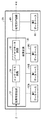
図4は、パケット処理回路の内部構成を示す。パケット処理回路20は、通信データに対して実行する処理の内容を決定するための基準となる基準データを記憶する第1データベース50A、50B、及び50C(これらを総称して「第1データベース50」という)と、受信された通信データの中に基準データが含まれているか否かを、通信データと基準データとを比較することにより検索する検索回路30と、検索回路30による検索結果と通信データに対して実行する処理の内容とを対応づけて記憶する第2データベース60と、検索回路30による検索結果と第2データベース60に記憶された条件とに基づいて通信データを処理する処理実行回路40とを含む。
FIG. 4 shows the internal configuration of the packet processing circuit. The
検索回路30は、通信データの中から基準データと比較すべき比較対象データの位置を検出する位置検出回路32と、第1データベース50に記憶された基準データを3以上の範囲に分割したとき、比較対象データがそれらの範囲のうちいずれに属するかを判定する判定回路の一例であるインデックス回路34と、判定された範囲の中で比較対象データと合致する基準データを検索するバイナリサーチ回路36とを含む。比較対象データを基準データの中から検索する方法としては、任意の検索技術を利用可能であるが、本前提技術ではバイナリサーチ法を用いる。本前提技術では、後述するように、改良されたバイナリサーチ法を用いるので、そのために第1データベース50を3つ設けている。第1データベース50A、50B、及び50Cには、同じ基準データが格納されている。
When the
図5は、位置検出回路の内部構成を示す。位置検出回路32は、比較対象データの位置を特定するための位置特定データと通信データとを比較するための複数の比較回路33a〜33fを含む。ここでは、6個の比較回路33a〜33fが設けられているが、後述するように、比較回路の個数は任意でよい。それぞれの比較回路33a〜33fには、通信データが、所定のデータ長、例えば、1バイトずつずらして入力される。そして、これら複数の比較回路33a〜33fにおいて、同時に並列して、検出すべき位置特定データと通信データとの比較がなされる。
FIG. 5 shows the internal configuration of the position detection circuit. The
本前提技術においては、通信制御装置10の動作を説明するための例として、通信データ中に含まれる「No. ###」という文字列を検出し、その文字列中に含まれる数字「###」を基準データと比較して、基準データに合致した場合はパケットの通過を許可し、合致しなかった場合はパケットを破棄する処理を行う場合について説明する。
In the base technology, as an example for explaining the operation of the
図5の例では、通信データの中から、数字「###」の位置を特定するための位置特定データ「No.」を検出するために、通信データ「01No. 361・・・」を、1文字ずつずらして比較回路33a〜33fに入力している。すなわち、比較回路33aには「01N」が、比較回路33bには「1No」が、比較回路33cには「No.」が、比較回路33dには「o. 」が、比較回路33eには「. 3」が、比較回路33fには「 36」が、それぞれ入力される。ここで、比較回路33a〜33fが同時に位置特定データ「No.」との比較を実行する。これにより、比較回路33cがマッチし、通信データの先頭から3文字目に「No.」という文字列が存在することが検出される。こうして、位置検出回路32により検出された位置特定データ「No.」の次に、比較対象データである数字のデータが存在することが検出される。
In the example of FIG. 5, in order to detect the position specifying data “No.” for specifying the position of the number “####” from the communication data, the communication data “01No. 361. Each character is shifted and input to the
CPUにより同様の処理を行うならば、まず、文字列「01N」を「No.」と比較し、続いて、文字列「1No」を「No.」と比較する、というように、先頭から順に1つずつ比較処理を実行する必要があるため、検出速度の向上は望めない。これに対し、本前提技術の通信制御装置10では、複数の比較回路33a〜33fを並列に設けることにより、CPUではなしえなかった同時並列的な比較処理が可能となり、処理速度を格段に向上させることができる。比較回路は多ければ多いほど同時に比較可能な位置が多くなるので、検出速度も向上するが、コスト、サイズ、などを考慮の上、所望の検出速度を得られるのに十分な数の比較回路を設ければよい。
If similar processing is performed by the CPU, first, the character string “01N” is compared with “No.”, and then the character string “1No” is compared with “No.”. Since it is necessary to execute comparison processing one by one, improvement in detection speed cannot be expected. On the other hand, in the
位置検出回路32は、位置特定データを検出するためだけでなく、汎用的に文字列を検出する回路として利用されてもよい。また、文字列だけでなく、ビット単位で位置特定データを検出するように構成されてもよい。
The
図6は、位置検出回路の別の例を示す。図6に示した例では、位置検出回路32に設けられたそれぞれの比較回路33a〜33fのデータ長よりも位置特定データの方が短い場合は、位置特定データの後に所定のデータ、例えば、「00H」又は「01H」などをパディングする。また、位置特定データと比較する通信データについても、位置特定データと同じデータ長のみを抜き出して、その後に、位置特定データにパディングしたデータと同じデータをパディングする。このとき、通信データ自身を改変しないために、通信データをワークとしてコピーし、コピーしたデータを加工して比較回路33a〜33fに入力してもよい。これにより、位置特定データのデータ長によらず、位置検出回路32を汎用的に用いることができる。
FIG. 6 shows another example of the position detection circuit. In the example illustrated in FIG. 6, when the position specifying data is shorter than the data length of each of the
図7は、位置検出回路の更に別の例を示す。図7に示した例では、図6に示した例と同様に、位置特定データの後に所定のデータをパディングするが、このデータをワイルドカードとして扱う。すなわち、比較回路33a〜33fは、ワイルドカードであるデータが入力されると、比較対象のデータが何であっても無条件に合致したと判定する。これにより、位置特定データのデータ長によらず、位置検出回路32を汎用的に用いることができる。
FIG. 7 shows still another example of the position detection circuit. In the example shown in FIG. 7, as in the example shown in FIG. 6, predetermined data is padded after the position specifying data, but this data is treated as a wild card. In other words, when data that is a wild card is input, the
図8は、第1データベースの内部データの例を示す。第1データベース50には、パケットのフィルタリング、ルーティング、スイッチング、置換などの処理の内容を決定するための基準となる基準データが、何らかのソート条件にしたがって昇順又は降順にソートされて格納されている。図8の例では、1000個の基準データが記憶されている。
FIG. 8 shows an example of internal data of the first database. The
インデックス回路34は、第1データベース50に格納されている基準データを3以上の範囲52a〜52dに分割したとき、比較対象データがそれらの範囲のうちいずれに属するかを判定する。図8の例では、1000個の基準データは、250個ずつ4つの範囲52a〜52dに分割されている。インデックス回路34は、範囲の境界の基準データと比較対象データとを比較する複数の比較回路35a〜35cを含む。比較回路35a〜35cにより比較対象データと境界の基準データとを同時に並列して比較することにより、比較対象データがいずれの範囲に属するかを1度の比較処理で判定することができる。
When the reference data stored in the
インデックス回路34の比較回路35a〜35cに入力される境界の基準データは、通信制御装置10の外部に設けられた装置により設定されてもよいし、予め第1データベース50の所定位置の基準データが自動的に入力されるようにしてもよい。後者の場合、第1データベース50を更新しても、自動的に第1データベース50の所定位置の基準データが比較回路35a〜35cに入力されるので、初期設定などを必要とせず、直ちに通信制御処理を実行させることができる。
The boundary reference data input to the
前述したように、CPUによりバイナリサーチを実行する場合は、同時に複数の比較を実行することができないが、本前提技術の通信制御装置10では、複数の比較回路35a〜35cを並列に設けることにより、同時並列的な比較処理を可能とし、検索速度を格段に向上させることができる。
As described above, when a binary search is executed by the CPU, a plurality of comparisons cannot be executed at the same time. However, in the
インデックス回路34により範囲が判定されると、バイナリサーチ回路36がバイナリサーチ法により検索を実行する。バイナリサーチ回路36は、インデックス回路34により判定された範囲をさらに2n個に分割し、その境界位置にある基準データと比較対象データとを比較することにより、いずれの範囲に属するかを判定する。バイナリサーチ回路36は、基準データと比較対象データとをビット単位で比較する比較器を複数個、例えば本前提技術では1024個含んでおり、1024ビットのビットマッチングを同時に実行する。2n分割された範囲のいずれに属するかが判定されると、さらに、その範囲を2n分割して境界位置にある基準データを読み出し、比較対象データと比較する。以降、この処理を繰り返すことにより範囲をさらに限定し、最終的に比較対象データと合致する基準データを検索する。When the range is determined by the
前述した例を用いてさらに詳細に動作を説明する。インデックス回路34の比較回路35a〜35cには、比較対象データとして「361」が入力され、基準データとして、比較回路35aには、範囲52aと52bの境界にある基準データ「378」が、比較回路35bには、範囲52bと52cの境界にある基準データ「704」が、比較回路35cには、範囲52cと52dの境界にある基準データ「937」が、それぞれ入力される。比較回路35a〜35cにより同時に比較が行われ、比較対象データ「361」が範囲52aに属することが判定される。以降、バイナリサーチ回路36が基準データの中に比較対象データ「361」が存在するか否かを検索する。
The operation will be described in more detail using the example described above. “361” is input as comparison target data to the
図9は、第1データベースの内部データの別の例を示す。図9に示した例では、基準データのデータ数が、第1データベース50に保持可能なデータ数、ここでは1000個よりも少ない。このとき、第1データベース50には、最終データ位置から降順に基準データが格納される。そして、残りのデータには0が格納される。データベースのローディング方法として、先頭からデータを配置せずにローディングエリアの後方から配置し、ローディングエリア先頭に空きが生じた場合は全ての空きをゼロサプレスすることで、データーベースは常にフルの状態になり、バイナリー検索する場合の検索時間を一定にすることができる。また、バイナリサーチ回路36は、検索中に基準データとして「0」を読み込んだときには、比較結果が自明であるから、比較を行わずに範囲を特定して、次の比較にうつることができる。これにより、検索速度を向上させることができる。
FIG. 9 shows another example of internal data of the first database. In the example shown in FIG. 9, the number of reference data is less than the number of data that can be held in the
CPUによるソフトウェア処理においては、第1データベース50に基準データを格納する際に、最初のデータ位置から昇順に基準データが格納される。残りのデータには、例えば最大値が格納されることになるが、この場合、バイナリサーチにおいて、上述したような比較処理の省略はできない。上述した比較技術は、専用のハードウェア回路により検索回路30を構成したことにより実現される。
In the software processing by the CPU, when the reference data is stored in the
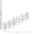
図10は、第1データベースの内部データのさらに別の例を示す。図10に示した例では、基準データを均等に3以上の範囲に分割するのではなく、範囲52aは500個、範囲52bは100個というように、範囲に属する基準データの数が不均一になっている。これらの範囲は、通信データ中における基準データの出現頻度の分布に応じて設定されてもよい。すなわち、それぞれの範囲に属する基準データの出現頻度の和がほぼ同じになるように範囲が設定されてもよい。これにより、検索効率を向上させることができる。インデックス回路34の比較回路35a〜35cに入力される基準データは、外部から変更可能になっていてもよい。これにより、範囲を動的に設定することができ、検索効率を最適化することができる。
FIG. 10 shows still another example of internal data of the first database. In the example shown in FIG. 10, the number of reference data belonging to the range is not uniform, for example, the
図11は、インデックス回路の別の例を示す。図8〜10に示した例では、インデックス回路34は、3つの比較回路35a〜35cを用いて、比較対象データが第1データベース50の4つの範囲52a〜52dのいずれに属するかを判定したが、図11の例では、インデックス回路34には、比較対象データが、4つの範囲52a〜52dのそれぞれに含まれるか否かを判定するための4つの比較回路35d〜35gが設けられている。例えば、比較回路35dには、第1データベース50の0件目の基準データと、250件目の基準データと、比較対象データとが入力され、それぞれの基準データと比較対象データとを比較することにより、基準データが範囲52aに含まれるか否かを判定する。それぞれの比較回路35d〜35gの比較結果は判定回路35zに入力され、判定回路35zから、基準データがいずれの範囲に含まれているかが出力される。比較回路35d〜35gは、基準データが入力された2つの基準データの間に含まれるか否かを出力してもよいし、範囲よりも大きい、範囲に含まれる、範囲よりも小さい、のいずれかを出力してもよい。比較対象データが、範囲52a〜52dのいずれにも含まれないと判定された場合は、比較対象データが第1データベース50中に存在しないことが分かるので、以降のバイナリサーチを行うまでもなく、検索を終了することができる。
FIG. 11 shows another example of the index circuit. In the example shown in FIGS. 8 to 10, the
図12は、バイナリサーチ回路に含まれる比較回路の構成を示す。前述したように、バイナリサーチ回路36に含まれる比較回路は、1024個の比較器36a、36b、・・・、を含む。それぞれの比較器36a、36b、・・・、には、基準データ54と比較対象データ56が1ビットずつ入力され、それらの大小が比較される。インデックス回路34の各比較回路35a〜35cの内部構成も同様である。このように、専用のハードウェア回路で比較処理を実行することにより、多数の比較回路を並列して動作させ、多数のビットを同時に比較することができるので、比較処理を高速化することができる。
FIG. 12 shows the configuration of the comparison circuit included in the binary search circuit. As described above, the comparison circuit included in the
図13は、バイナリサーチ回路の構成を示す。バイナリサーチ回路36は、図12に示した1024個の比較器36a、36b、・・・を含む比較回路36A、36B、及び36Cと、それらの比較回路を制御する制御回路36Zを含む。
FIG. 13 shows the configuration of the binary search circuit. The
従来のバイナリサーチ法では、まず1回目は、データが昇順又は降順に整列されたデータベースの探索対象範囲の1/2の位置にあるデータを読み出して比較対象データと比較する。データが昇順に並べられている場合、比較対象データの方が小さければ、比較対象データは探索対象範囲の前半に存在するので、2回目は前半を探索対象範囲としてその1/2、すなわち最初の探索対象範囲の1/4の位置にあるデータを読み出して比較対象データと比較する。逆に、比較対象データの方が大きければ、比較対象データは探索対象範囲の後半に存在するので、2回目は後半を探索対象範囲としてその1/2、すなわち最初の探索対象範囲の3/4の位置にあるデータを読み出して比較対象データと比較する。このように、探索対象範囲を半分ずつ絞っていき、最終的に対象データに到達する。 In the conventional binary search method, first, data at a position half the search target range of a database in which data is arranged in ascending or descending order is read and compared with comparison target data. When the data is arranged in ascending order, if the comparison target data is smaller, the comparison target data exists in the first half of the search target range, so the second time uses the first half as the search target range, that is, the first Data at a position ¼ of the search target range is read and compared with the comparison target data. On the other hand, if the comparison target data is larger, the comparison target data exists in the latter half of the search target range. Therefore, in the second time, the second half is set as the search target range, that is, 3/4 of the first search target range. The data at the position is read out and compared with the comparison target data. In this way, the search target range is narrowed by half and finally reaches the target data.
本前提技術では、バイナリサーチのための比較回路を3つ設けているので、1回目の探索のために探索対象範囲の1/2の位置にあるデータと比較対象データとを比較させるときに、同時に並行して、2回目の探索のために探索対象範囲の1/4及び3/4の位置にあるデータと比較対象データとを比較させる。これにより、2回分の探索を一度に行うことができるので、データベースからデータを読み上げる時間を短縮することができる。また、3つの比較回路を同時に並列して動作させることにより、比較の回数を半分に抑え、探索に要する時間を短縮することができる。
In the base technology, since three comparison circuits for binary search are provided, when comparing the data in the half of the search target range with the comparison target data for the first search, At the same time, the comparison target data is compared with the data at the
図13の例では、2回分の探索を同時に行うために、3つの比較回路を設けたが、一般に、n回分の探索を同時に並行して行うためには、2n−1個の比較回路を設ければよい。制御回路36Zは、探索対象範囲の1/2n、2/2n、・・・、(2n−1)/2nの位置のデータを、2n−1個の比較回路のそれぞれに入力させ、それらを同時に並列して動作させて比較対象データと比較させる。制御回路36Zは、それぞれの比較回路の比較結果を取得して、比較対象データが探索されたか否かを判定する。制御回路36Zは、いずれかの比較回路が、データが一致した旨の信号を出力した場合、比較対象データが探索されたと判定して、バイナリサーチを終了する。一致した旨の信号が出力されなかった場合、次回の探索に移る。比較対象データがデータベースに存在するならば、2n−1個の比較回路の比較結果が反転する範囲に存在するはずである。例えば、15個の比較回路が設けられているときに、5/16の位置のデータが比較対象データより小さく、6/16の位置のデータが比較対象データより大きければ、5/16から6/16の間の範囲に比較対象データがある。したがって、制御回路36Zは、各比較回路の比較結果を取得して、比較結果が反転した範囲を次回の探索対象範囲と決定し、決定された次回の探索対象範囲の1/2n、2/2n、・・・、(2n−1)/2nの位置のデータをそれぞれの比較回路へ入力させる。In the example of FIG. 13, three comparison circuits are provided in order to perform two searches simultaneously. In general, in order to perform n searches in parallel at the same time, 2 n −1 comparison circuits are provided. What is necessary is just to provide. The
本前提技術では、第1データベース50を3つ設けており、第1データベース50Aは比較回路36Aに接続されて探索対象範囲の1/4の位置にあるデータを比較回路36Aに供給し、第1データベース50Bは比較回路36Bに接続されて探索対象範囲の2/4の位置にあるデータを比較回路36Bに供給し、第1データベース50Cは比較回路36Cに接続されて探索対象範囲の3/4の位置にあるデータを比較回路36Cに供給する。これにより、それぞれの比較回路にデータを同時に並行して読み上げることができるので、データの読み上げに要する時間を更に短縮し、バイナリサーチを高速化することができる。
In the base technology, three
比較回路は多ければ多いほど探索速度も向上するが、コスト、サイズなどを考慮の上、所望の探索速度を得られるのに十分な数の比較回路を設ければよい。また、比較回路の数と同じだけ第1データベースを設けるのが好ましいが、コスト、サイズなどを考慮の上、いくつかの比較回路でデータベースを共用してもよい。 As the number of comparison circuits increases, the search speed improves. However, in consideration of cost, size, etc., a sufficient number of comparison circuits may be provided to obtain a desired search speed. Although it is preferable to provide as many first databases as the number of comparison circuits, in consideration of cost, size, etc., the databases may be shared by several comparison circuits.
図14は、第1データベースの内部データの更に別の例を示す。図14に示した第1データベース50は、フィルタリングの対象となるコンテンツのURLを格納している。第1データベース50に格納されるデータは、ワイルドカードとして認識される所定のデータ、例えば、「00H」又は「01H」などを含んでもよい。図14に示した例において、「http://www.xx.xx/*********」は、「*********」がワイルドカードとして認識され、比較器36a、36b、・・・において、比較対象データが何であっても合致すると判定される。したがって、「http://www.xx.xx/」で始まる文字列は全てバイナリサーチ回路36により検出される。これにより、例えば、ドメイン「http://www.xx.xx/」の配下にあるコンテンツの全てにフィルタリングをかける処理などを容易に行うことができる。
FIG. 14 shows still another example of internal data of the first database. The
図15は、第2データベースの内部データの例を示す。第2データベース60は、検索回路30による検索結果を格納する検索結果欄62と、通信データに対して実行する処理の内容を格納する処理内容欄64とを含み、検索結果と処理内容とを対応づけて保持する。図15の例では、通信データに基準データが含まれている場合は、そのパケットの通過を許可し、含まれていない場合は、そのパケットを破棄するという条件が設定されている。処理実行回路40は、検索結果に基づいて第2データベース60から処理内容を検索し、通信データに対して処理を実行する。処理実行回路40も、ワイヤードロジック回路により実現されてもよい。
FIG. 15 shows an example of internal data of the second database. The
図16は、第2データベースの内部データの別の例を示す。図16の例では、基準データごとに、処理内容が設定されている。パケットの置換を行う場合、置換先のデータを第2データベース60に格納しておいてもよい。パケットのルーティングやスイッチングを行う場合、経路に関する情報を第2データベース60に格納しておいてもよい。処理実行回路40は、検索回路30による検索結果に応じて、第2データベース60に格納された、フィルタリング、ルーティング、スイッチング、置換などの処理を実行する。図16のように、基準データごとに処理内容を設定する場合、第1データベース50と第2データベース60とを統合してもよい。
FIG. 16 shows another example of internal data of the second database. In the example of FIG. 16, the processing content is set for each reference data. When packet replacement is performed, replacement destination data may be stored in the
第1のデータベース及び第2のデータベースは、外部から書き換え可能に設けられる。これらのデータベースを入れ替えることにより、同じ通信制御装置10を用いて、さまざまなデータ処理や通信制御を実現することができる。また、検索対象となる基準データを格納したデータベースを2以上設けて、多段階の検索処理を行ってもよい。このとき、検索結果と処理内容とを対応づけて格納したデータベースを2以上設けて、より複雑な条件分岐を実現してもよい。このように、データベースを複数設けて多段階の検索を行う場合に、位置検出回路32、インデックス回路34、バイナリサーチ回路36などを複数設けてもよい。
The first database and the second database are rewritable from the outside. By exchanging these databases, various data processing and communication control can be realized using the same
上述した比較に用いられるデータは、同じ圧縮ロジックにより圧縮されてもよい。比較に際して、比較元のデータと比較先のデータが同じ方式で圧縮されていれば、通常と同様の比較が可能である。これにより、比較の際にローディングするデータ量を低減することができる。ローディングするデータ量が少なくなれば、メモリからデータを読み出すのに要する時間が短縮されるので、全体の処理時間も短縮することができる。また、比較器の量を削減することができるので、装置の小型化、軽量化、低コスト化に寄与することができる。比較に用いられるデータは、圧縮された形式で格納されていてもよいし、メモリから読み出した後、比較の前に圧縮されてもよい。 The data used for the comparison described above may be compressed by the same compression logic. In comparison, if the comparison source data and the comparison destination data are compressed by the same method, the same comparison as usual is possible. As a result, the amount of data loaded at the time of comparison can be reduced. If the amount of data to be loaded is reduced, the time required to read data from the memory is reduced, so that the overall processing time can also be reduced. Further, since the amount of the comparator can be reduced, it is possible to contribute to downsizing, weight reduction, and cost reduction of the apparatus. The data used for the comparison may be stored in a compressed form, or may be compressed after being read from the memory and before the comparison.
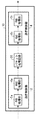
図17は、前提技術の通信制御装置の別の構成例を示す。本図に示した通信制御装置10は、図4に示した通信制御装置10と同様の構成を備える通信制御ユニット12を2つ有している。また、それぞれの通信制御ユニット12の動作を制御する切替制御部14が設けられている。それぞれの通信制御ユニット12は、2つの入出力インタフェース16を有しており、それぞれの入出力インタフェース16を介して、上流側、下流側の2つのネットワークに接続されている。通信制御ユニット12は、いずれか一方のネットワークから通信データを入力し、処理したデータを他方のネットワークに出力する。切替制御部14は、それぞれの通信制御ユニット12に設けられた入出力インタフェース16の入出力を切り替えることにより、通信制御ユニット12における通信データの流れの方向を切り替える。これにより、一方向だけではなく、双方向の通信制御が可能となる。
FIG. 17 shows another configuration example of the communication control apparatus of the base technology. The
切替制御部14は、通信制御ユニット12の一方がインバウンド、他方がアウトバウンドのパケットを処理するように制御してもよいし、双方がインバウンドのパケットを処理するように制御してもよいし、双方がアウトバウンドのパケットを処理するように制御してもよい。これにより、例えばトラフィックの状況や目的などに応じて、制御する通信の方向を可変とすることができる。
The switching
切替制御部14は、各通信制御ユニット12の動作状況を取得し、その動作状況に応じて通信制御の方向を切り替えてもよい。例えば、一方の通信制御ユニット12を待機状態として、他方の通信制御ユニット12を動作させている場合に、その通信制御ユニット12が故障などにより停止したことを検知したときに、代替として待機中の通信制御ユニット12を動作させてもよい。これにより、通信制御装置10のフォールトトレランスを向上させることができる。また、一方の通信制御ユニット12に対して、データベースの更新などのメンテナンスを行うときに、他方の通信制御ユニット12を代替として動作させてもよい。これにより、通信制御装置10の運用を停止させずに、適切にメンテナンスを行うことができる。
The switching
通信制御装置10に3以上の通信制御ユニット12が設けられてもよい。切替制御部14は、例えば、トラフィックの状況を取得して、通信量の多い方向の通信制御処理に、より多くの通信制御ユニット12を割り当てるように、各通信制御ユニット12の通信の方向を制御してもよい。これにより、ある方向の通信量が増加しても、通信速度の低下を最小限に抑えることができる。
Three or more communication control units 12 may be provided in the
図18は、複数の通信制御装置10a、10b、10c、・・・、を含む通信制御装置10の構成を示す。第1データベース50は、データ数に比例して大きな容量を必要とするので、分割して通信制御装置10a、10b、10c、・・・、に保持させる。後述するように、本前提技術の通信制御システム100では、処理すべき通信パケットを、運用中の全ての通信制御装置10a、10b、10c、・・・、に供給し、それぞれの通信制御装置10が受け取ったパケットを処理する。例えば、通信制御装置10aは、データIDが「000001」から「100000」まで、通信制御装置10bは、データIDが「100001」から「200000」まで、通信制御装置10cは、データIDが「200001」から「300000」までのデータを保持しており、それぞれが保持するデータを参照してパケットを処理する。
FIG. 18 shows a configuration of the
図19は、運用監視サーバ110に設けられた管理テーブル111の内部データの例を示す。管理テーブル111には、装置ID欄112、運用状況欄113、データID欄114が設けられている。装置ID欄112には、通信制御装置10a、10b、・・・、の装置IDが格納され、運用状況欄113には、その通信制御装置の運用状況が格納され、データID欄114には、その通信制御装置が担当すべきデータIDの範囲が格納される。運用状況には、例えば、「運用中」、「スタンバイ」、「故障中」、「データ更新中」などがある。運用状況欄113は、通信制御装置10a、10b、・・・、の運用状況が変更されるたびに、運用監視サーバ110により更新される。図19に示した例では、「465183」件のデータが第1データベース50に格納されるので、装置ID「1」〜「5」の5台の通信制御装置10が運用されており、装置ID「6」の通信制御装置10はスタンバイ状態となっている。
FIG. 19 shows an example of internal data of the management table 111 provided in the
運用監視サーバ110は、複数の通信制御装置10の運用状況を監視し、いずれかの通信制御装置10においてトラブルが発生して運用不可能な状態になったことを検知したときには、スタンバイ状態となっている通信制御装置10に、運用が停止した通信制御装置10と同じデータを格納し、その通信制御装置10に運用を切り替える。例えば、図20に示すように、装置ID「2」の通信制御装置10が故障により運用停止した場合、スタンバイ状態であった装置ID「6」の通信制御装置10に、データID「100001〜200000」のデータを格納して運用を開始させる。これにより、何らかのトラブルで通信制御装置10が停止されるような状況になっても、適切に運用を継続することができる。スタンバイ中の通信制御装置10には、予めいずれかのデータを格納しておき、ホットスタンバイ状態にしておいてもよいし、コールドスタンバイ状態にしておいてもよい。
The
次に、通信制御装置10に含まれるデータベースを更新する手順について説明する。データベースサーバ150は、所定のタイミングで外部のデータベースから最新のデータベースを取得して保持する。運用監視サーバ110は、所定のタイミングで、データベースサーバ150に保持された最新のデータベースを通信制御装置10に反映させるために、データベースサーバ150から通信制御装置10にデータを転送して格納させる。
Next, a procedure for updating a database included in the
図21(a)(b)(c)は、データベースを更新する様子を説明するための図である。図21(a)は、図19と同様に、装置ID「1」〜「5」の通信制御装置10が運用中であり、装置ID「6」の通信制御装置10がスタンバイ中である状況を示す。運用監視サーバ110は、データベースを更新するタイミングが到来すると、現在スタンバイ状態である通信制御装置10を特定し、その通信制御装置10に対してデータを格納するようデータベースサーバ150に指示する。図21(a)の例では、装置ID「6」の通信制御装置10がスタンバイ中であるから、この通信制御装置10にデータベースサーバ150からデータが格納される。このとき、運用監視サーバ110は、装置ID「6」の運用状況欄113を「データ更新中」に変更する。
FIGS. 21A, 21B, and 21C are diagrams for explaining how the database is updated. FIG. 21A shows a situation where the
図21(b)は、通信制御装置10のデータベースが更新中である状況を示す。データベースサーバ150は、運用中の通信制御装置10のいずれかが担当するデータを、スタンバイ中であった装置ID「6」の通信制御装置10の第1データベース50に格納する。図21(b)の例では、装置ID「1」の通信制御装置10が担当していた、データID「000001〜100000」のデータを、装置ID「6」の通信制御装置10に格納している。
FIG. 21B shows a situation where the database of the
図21(c)は、装置ID「6」の通信制御装置10のデータベースが更新されて運用が開始され、代わって装置ID「1」の通信制御装置10がスタンバイ状態となった状況を示す。運用監視サーバ110は、装置ID「6」の通信制御装置10に対するデータの格納が終了すると、更新後のデータベースを保持する装置ID「6」の通信制御装置10の運用を開始すると同時に、更新前のデータベースを保持する装置ID「1」の通信制御装置10の運用を停止してスタンバイ状態にする。これにより、データベースが更新された通信制御装置10に運用が切り替えられる。つづいて、装置ID「1」の通信制御装置10に、データID「100001〜200000」のデータを格納した後、装置ID「1」の通信制御装置10を運用開始し、装置ID「2」の通信制御装置10の運用を停止する。以降、同様に、巡回的にデータベースを更新していくことで、通信制御システム100の運用を停止することなく、全ての通信制御装置10のデータベースを背後で更新することができる。
FIG. 21C illustrates a situation in which the database of the
このように、本前提技術の通信制御装置10では、各通信制御装置10に格納されているデータは固定的ではなく、あるデータがいずれの通信制御装置10に格納されているかは、時間によって移り変わる。各通信制御装置10にパケットを送る前に、いずれの通信制御装置10にそのユーザのデータが存在するかを判定する処理を行うと、その処理に要する時間が余分にかかる。そのため、本実施の形態では、受信したパケットを全ての通信制御装置10へ供給し、各通信制御装置10がパケットを処理する。以下、このような仕組みを実現するための技術について説明する。
As described above, in the
図22は、複数の通信制御装置10によりパケットを処理するために設けられた通信経路制御装置の構成を示す。通信経路制御装置200は、スイッチ210、データ供給ユニットの一例である光スプリッタ220、及びスイッチ230を備える。スイッチ210は、受信したパケットを通信制御装置10へ送信する。ここで、スイッチ210と通信制御装置10の間には、複数の通信制御装置10a、10b、10cにパケットを並行して供給するための光スプリッタ220が設けられており、スイッチ210は、実際には光スプリッタ220へパケットを送信し、光スプリッタ220が各通信制御装置へパケットを並行して送信する。
FIG. 22 shows a configuration of a communication path control device provided for processing a packet by a plurality of
複数の通信制御装置10a、10b、10cへパケットを送信するために、パケットをブロードキャストに変換すると、例えばヘッダにタイムスタンプを追加するなどの余分な処理が発生し、処理速度が低下してしまう。そのため、パケットに変更を加えずに、光スプリッタ220により分割して、ユニキャストのまま複数の通信制御装置10a、10b、10cへパケットを送信する。この方式を、本明細書では「パラレルキャスト」と呼ぶ。
If a packet is converted into a broadcast in order to transmit the packet to a plurality of
各通信制御装置は、自装置のMACアドレス宛のパケットのみを受信するモードではなく、宛先のMACアドレスに関係なく全てのパケットを受信するプロミスキャスモードに設定される。各通信制御装置は、光スプリッタ220からパラレルキャストされたパケットを受信すると、MACアドレスのマッチング処理を省き、全てのパケットを取得して処理する。
Each communication control device is set to a promiscuous mode that receives all packets regardless of the destination MAC address, not a mode that receives only packets addressed to its own MAC address. When each communication control device receives a parallel-cast packet from the
通信制御装置10cは、通信が禁止された場合など、送信元宛にパケットを返信する場合には、光スプリッタ220を介さずにスイッチ210へ応答パケットを送信する。通信制御装置10cは、パケットを処理した結果、通信が許可された場合は、そのパケットをネットワークへ送出する。ここで、通信制御装置10と上流の通信回線の間には、複数の通信制御装置10a、10b、10cから送出されるパケットを集約するためのスイッチ230が設けられており、通信制御装置10cは、実際にはスイッチ230へパケットを送信し、スイッチ230が上流の通信回線へパケットを送出する。
The
パケットの送信先から返信されたパケットをスイッチ230が受信したときに、返信されたパケットが通信制御装置10による処理を必要としない場合は、スイッチ230のポート232からスイッチ210のポート212へ送信され、スイッチ210から送信元に向けて送出される。通常、インターネットでは、パケットに対する応答パケットが確実に送信元に返信されるよう、返信経路を確保するために、送信時の経路がパケットに記録される。しかし、本実施の形態では、通信経路制御装置200内における返信経路が予め用意されているので、経路を記録せずに、すなわち、パケットを加工せずに装置間の通信を行う。これにより、無駄な処理を省き、処理速度を向上させることができる。
When the
図22の例では、送信元から発信されたパケットを送信先へ送出する場合にのみパケットを処理し、送信先から送信元へ送出された応答パケットは処理せずに通過させる場合の構成を示しているが、通信制御装置10が両方向のパケットを処理するように構成してもよい。この場合、通信制御装置10の両側に光スプリッタ220を設ければよい。また、スイッチ230からスイッチ210へのバイパス経路は設けなくてもよい。
The example of FIG. 22 shows a configuration in which a packet is processed only when a packet transmitted from the transmission source is transmitted to the transmission destination, and a response packet transmitted from the transmission destination to the transmission source is passed without being processed. However, the
このように、複数の通信制御装置のうち、パケットを処理すべき通信制御装置を予め特定しなくても、全ての通信制御装置に同じパケットをパラレルキャストすることにより、処理すべき通信制御装置に適切にパケットを処理させることができる。 In this way, even if the communication control device that should process the packet is not specified in advance among the plurality of communication control devices, the same packet is parallel-cast to all the communication control devices, so that Packets can be processed appropriately.
これらの通信制御装置は、上述したように、通信経路制御装置200からパラレルキャストされる全てのパケットを受信して処理又は破棄するので、インターネット上で装置を一意に識別するためのIPアドレスを付与しておく必要がない。サーバ装置などにより、上述したようなパケット処理を実行する場合は、サーバ装置に対する攻撃を考慮する必要があるが、本実施の形態の通信制御装置は、インターネットを介して悪意ある第三者から直接攻撃を受けることがないので、安全に通信制御を行うことができる。
As described above, these communication control devices receive and process or discard all packets that are parallel-cast from the communication
(実施の形態)
図23は、実施の形態に係る通信管理システムの構成を示す。通信管理システム300は、パケットフィルタリングなどの機能を有する通信制御装置10を用いて、ボットを操作するための通信など、不適切な通信を検知して遮断するための処理を行う。(Embodiment)
FIG. 23 shows a configuration of a communication management system according to the embodiment. The
前述したように、ボットは、ユーザ端末310に感染して被害をもたらす。ボットが感染したユーザ端末(以下、「ボット320」という)は、攻撃者の意のままに操られ、攻撃者の端末として振る舞う。したがって、ボット320を操作する通信や、ボット320が他のユーザ端末310を攻撃する通信を検知して遮断することが望まれる。
As described above, the bot infects the
しかし、ソースコードが公開されたボットをもとに、新しい亜種が次々と登場しているので、ボット320や、複数のボット320により構成されるボットネット322に対して送受信される不適切な通信データの全てを確実に検知することは難しい。
However, since new variants appear one after another based on the bots whose source code has been released, they are inappropriately transmitted to and received from the
したがって、本実施の形態では、発想を逆転させ、正常な通信のシグネチャリストを作成して正常な通信を通過させる一方、正常ではない通信を逐一エスカレーションして解析し、正常な通信のシグネチャリストと異常な通信のシグネチャリストを随時更新していく技術を提案する。この技術により、ボットネットによる被害が軽減されることが期待されるため、本発明の社会的な貢献度は非常に高いと言える。 Therefore, in the present embodiment, the idea is reversed, a normal communication signature list is created and normal communication is allowed to pass, while non-normal communication is escalated and analyzed one by one. We propose a technique to update the abnormal communication signature list as needed. Since this technology is expected to reduce the damage caused by the botnet, it can be said that the social contribution of the present invention is very high.
通信管理システム300において、ユーザ端末310とインターネット390の間に通信制御装置10が設けられており、インターネット390を介して送受信される通信データが制御される。通信制御装置10は、正常でない通信データを検知すると、運用者端末340へ通知する。運用者端末340において、該当する通信データが解析され、その通信データが正常であるか否かが判定される。正常であると判定された通信データのシグネチャは通信制御装置10に反映され、以降、この通信データと同種の通信データは送受信を許可される。異常であると判定された通信データのシグネチャも通信制御装置10に反映され、以降、この通信データと同種の通信データは送受信を禁止され遮断される。このようにして、通信制御装置10は、ボット320とボットネット322との間の通信や、インターネット390を介してボット320を操作するための通信などを検知して遮断する。
In the
本実施の形態の通信制御装置10には、第1データベース50として、正常シグネチャリスト332、異常シグネチャリスト334、及びルールデータベース336が設けられている。正常シグネチャリスト332は、正常な通信として通過させるべき通信データのシグネチャのリストを格納する。異常シグネチャリスト334は、異常な通信として遮断すべき通信データのシグネチャのリストを格納する。ルールデータベース336は、解析を要する通信データを抽出するためのルールを格納する。
In the
第1データベース50が3つ設けられているのに合わせて、検索回路30も3つ設けられている。検索回路30Aは、取得した通信データが正常シグネチャリスト332に格納された正常な通信のシグネチャに合致するか否かを検索する第1の検索部として機能する。検索回路30Bは、取得した通信データが異常シグネチャリスト334に格納された異常な通信のシグネチャに合致するか否かを検索する第2の検索部として機能する。検索回路30Cは、取得した通信データがルールデータベース336に格納されたルールに合致するか否かを検索する第3の検索部として機能する。これらの検索回路30のうち少なくとも2つ、好ましくは全ての検索回路30が、同時に並列して検索を実行する。これにより、スループットを低下させることなく、正常な通信、異常な通信、抽出すべき通信を高速に検知することができる。通信データを3つの検索回路30へ同時に供給するために、図22に示した技術を利用してもよい。
In addition to the three
第2データベース60には、正常シグネチャリスト332に格納された正常な通信のシグネチャに合致しない通信データを検知したときに、警告を発する旨の処理内容が格納されている。これに応じて、処理実行回路40は、検索回路30Aが正常シグネチャリスト332に格納されたシグネチャに合致しない通信データを検知すると、警告を発して運用者端末340へ通知する警告部として機能する。
The
また、第2データベース60には、異常シグネチャリスト334に格納された遮断すべき通信のシグネチャに合致する通信データを検知したときに、その通信データを遮断する旨の処理内容が格納されている。これに応じて、処理実行回路40は、検索回路30Bが異常シグネチャリスト334に格納されたシグネチャに合致する通信データを検知すると、その通信データを破棄して遮断する遮断部として機能する。
Further, the
運用者端末340では、警告取得部342が通信制御装置10から警告を取得すると、その旨を表示又は音声などにより運用者へ報知する。このとき、通信データ取得部344は、警告を発せられた通信データを通信制御装置10から取得する。解析部346は、警告を発せられた、正常な通信のシグネチャに合致しない通信データを解析し、正常な通信であるか否かを判定して判定結果取得部348へ伝達する。判定結果取得部348は、通信データを解析した運用者から判定結果を取得してもよい。また、運用者からエスカレーションされたセキュリティベンダーなどから判定結果を取得してもよい。
In the
判定結果取得部348は、警告を発せられた通信データが正常な通信データであるとの判定結果を取得したときに、正常シグネチャリスト362にその通信データのシグネチャを追加するよう正常シグネチャリスト更新部352へ指示する。正常シグネチャリスト更新部352は、正常シグネチャリスト362に、正常であると判定された通信データのシグネチャを追加する。
When the determination result acquisition unit 348 acquires the determination result that the communication data for which the warning has been issued is normal communication data, the normal signature list update unit adds the signature of the communication data to the
判定結果取得部348は、警告を発せられた通信データが遮断すべき通信データであるとの判定結果を取得したときに、異常シグネチャリスト364にその通信データのシグネチャを追加するよう異常シグネチャリスト更新部354へ指示する。異常シグネチャリスト更新部354は、異常シグネチャリスト364に、遮断すべきと判定された通信データのシグネチャを追加する。
When the determination result acquisition unit 348 acquires the determination result that the communication data for which the warning has been issued is communication data to be blocked, the determination result acquisition unit 348 updates the abnormality signature list so as to add the signature of the communication data to the abnormality signature list 364. Instruction to
更新された正常シグネチャリスト362及び異常シグネチャリスト364は、データベースサーバ150により、所定のタイミングで通信制御装置10の正常シグネチャリスト332及び異常シグネチャリスト334へ反映される。データベースの更新は、前提技術で説明した手順により行われてもよい。また、正常シグネチャリスト更新部352及び異常シグネチャリスト更新部354が、正常シグネチャリスト332及び異常シグネチャリスト334へ直接アクセスして更新してもよい。複数の通信制御装置10が設けられる場合は、データベースサーバ150が、それぞれの通信制御装置10により警告を発せられた通信データの判定結果を集約した正常シグネチャリスト362を作成し、集約された正常シグネチャリスト362をそれぞれの通信制御装置10の正常シグネチャリスト332に反映させる。
The updated
このように、異常な通信のみをシグネチャにより抽出して遮断するのではなく、正常な通信のみをシグネチャにより抽出して通過させ、それ以外の通信を解析し、正常か否かを判定して判定結果を反映させる。これにより、ボットネット322などにおいて新しい通信プロトコルにより不適切な通信が行われたとしても、それは正常な通信ではないので、確実に検知することができる。また、いったん遮断すべき通信データを検知すると、そのシグネチャを異常シグネチャリスト334に登録するので、以降は適切に遮断することができる。正常シグネチャリスト332及び異常シグネチャリスト334のシグネチャの量はかなり多くなるが、前提技術で説明したように、本実施の形態の通信制御装置10は、専用のハードウェアにより構成されていて、非常に高速な検索が可能であるから、スループットを低下させることなく適切に通信を管理することができる。
In this way, instead of extracting and blocking only abnormal communication by signature, only normal communication is extracted by signature and allowed to pass, and other communication is analyzed to determine whether it is normal or not. Reflect the results. As a result, even if inappropriate communication is performed by a new communication protocol in the
第2データベース60には、さらに、ルールデータベース336に格納されたルールに合致する通信データを検知したときに、その通信データを複製して出力する旨の処理内容が格納されている。これに応じて、処理実行回路40は、検索回路30Cがルールデータベース336に格納されたルールに合致する通信データを検知すると、その通信データの複製を出力ポートから運用者端末340へ出力する抽出部として機能する。
The
例えば、警告が発せられた通信データが正常であるか遮断すべきであるかを判定するにあたって、同じ送信元から送られた他の通信データや、同じ送信先へ送られた他の通信データなどを参照して解析する必要がある場合がある。このような場合に、警告が発せられた通信データの送信元のIPアドレス、送信先のIPアドレス、ペイロードの内容などをルールとしてルールデータベース336に登録しておけば、そのルールに合致した通信データを収集して解析することができる。前提技術で説明したように、本実施の形態の通信制御装置10は、送信元又は送信先のIPアドレスなど、ヘッダに格納された情報だけでなく、ペイロード部分に格納された情報も検索対象とすることができるので、より細かいルールの設定が可能である。
For example, other communication data sent from the same source or other communication data sent to the same destination in determining whether the communication data for which the warning has been issued is normal or should be blocked It may be necessary to analyze by referring to. In such a case, if the source IP address, destination IP address, payload content, etc. of the communication data for which the warning has been issued are registered in the
運用者は、警告を発せられた通信データを解析する際に、他の通信データも参照して解析すべきと判断した場合、ルールデータベース更新部356を介して、関連した通信データを抽出するためのルールをルールデータベース366に追加することができる。更新されたルールデータベース366は、データベースサーバ150により、通信制御装置10のルールデータベース336に反映される。これにより、シグネチャを随時変更可能なパケットキャプチャ装置を実現することができる。
When the operator analyzes the communication data for which the warning has been issued and determines that the communication data should be analyzed with reference to other communication data, the operator extracts relevant communication data via the rule
以上、本発明を実施の形態をもとに説明した。この実施の形態は例示であり、それらの各構成要素や各処理プロセスの組合せにいろいろな変形例が可能なこと、またそうした変形例も本発明の範囲にあることは当業者に理解されるところである。 The present invention has been described based on the embodiments. This embodiment is an exemplification, and it will be understood by those skilled in the art that various modifications can be made to combinations of the respective constituent elements and processing processes, and such modifications are also within the scope of the present invention. is there.
実施の形態では、正常シグネチャリスト332、異常シグネチャリスト334、ルールデータベース336と、それらを参照して通信データを検索する検索回路30A、30B、30Cを1つの通信制御装置10に設けたが、それぞれを別の通信制御装置10に設けてもよい。
In the embodiment, the
本発明は、不適切な通信を管理する通信管理システムに利用することができる。 The present invention can be used in a communication management system that manages inappropriate communication.
Claims (2)
通信データを取得し、その通信データが前記正常シグネチャリストに格納された正常な通信のシグネチャに合致するか否かを検索する第1の検索部と、
前記正常シグネチャリストに格納された正常な通信のシグネチャに合致しない通信データを検知したときに警告を発する警告部と、
通信データの中から、特定の通信データを出力させるためのルールを格納したルールデータベースと、
警告を発せられた通信データに関連した通信データを出力させるために、警告が発せられた通信データの送信元のIPアドレス、送信先のIPアドレス、又はペイロードの内容を前記ルールデータベースにルールとして登録する更新部と、
前記更新部が受け付けた前記ルールの変更を前記ルールデータベースにリアルタイムに反映させるデータベースサーバと、
通信データを取得し、その通信データが前記ルールデータベースに格納されたルールに合致するか否かを検索する第2の検索部と、
前記ルールデータベースに格納されたルールに合致する通信データを検知したときに、その通信データを複製して出力する出力部と、
を備えることを特徴とする通信管理システム。A normal signature list containing a list of normal communication signatures;
A first search unit that acquires communication data and searches whether the communication data matches a signature of normal communication stored in the normal signature list;
A warning unit that issues a warning when communication data that does not match a signature of normal communication stored in the normal signature list is detected;
A rule database storing rules for outputting specific communication data from communication data;
In order to output communication data related to the communication data for which the warning has been issued, the source IP address, the destination IP address, or the contents of the payload of the communication data for which the warning has been issued are registered as rules in the rule database. An update unit to
A database server for reflecting the change of the rule received by the update unit to the rule database in real time;
A second search unit that acquires communication data and searches whether the communication data matches a rule stored in the rule database;
When detecting communication data matching the rules stored in the rule database, an output unit for copying and outputting the communication data;
A communication management system comprising:
前記通信データを下流のネットワークへ送出する第2の通信制御部と、を更に備え、
前記出力部は、前記ルールに合致する通信データを複製して出力することを特徴とする請求項1に記載の通信管理システム。A first communication control unit that acquires communication data from an upstream network and supplies the communication data to the first or second search unit;
A second communication control unit for sending the communication data to a downstream network;
The communication management system according to claim 1, wherein the output unit duplicates and outputs communication data that matches the rule.
Applications Claiming Priority (1)
| Application Number | Priority Date | Filing Date | Title |
|---|---|---|---|
| PCT/JP2006/316649 WO2008023424A1 (en) | 2006-08-24 | 2006-08-24 | Communication management system and communication management method |
Publications (2)
| Publication Number | Publication Date |
|---|---|
| JPWO2008023424A1 JPWO2008023424A1 (en) | 2010-01-07 |
| JP4574675B2 true JP4574675B2 (en) | 2010-11-04 |
Family
ID=39106518
Family Applications (1)
| Application Number | Title | Priority Date | Filing Date |
|---|---|---|---|
| JP2007513543A Expired - Fee Related JP4574675B2 (en) | 2006-08-24 | 2006-08-24 | Communication management system |
Country Status (3)
| Country | Link |
|---|---|
| US (1) | US8463727B2 (en) |
| JP (1) | JP4574675B2 (en) |
| WO (1) | WO2008023424A1 (en) |
Families Citing this family (6)
| Publication number | Priority date | Publication date | Assignee | Title |
|---|---|---|---|---|
| US8665312B2 (en) * | 2010-12-06 | 2014-03-04 | Ricoh Company, Ltd. | Apparatus, system, and method of managing data transmission, and transmission management program |
| US9910904B2 (en) | 2011-08-30 | 2018-03-06 | International Business Machines Corporation | Replication of data objects from a source server to a target server |
| US8838529B2 (en) | 2011-08-30 | 2014-09-16 | International Business Machines Corporation | Applying replication rules to determine whether to replicate objects |
| CN103870291A (en) * | 2012-12-13 | 2014-06-18 | 鸿富锦精密工业(深圳)有限公司 | Upgrade system and upgrade method for electronic device |
| US10725708B2 (en) | 2015-07-31 | 2020-07-28 | International Business Machines Corporation | Replication of versions of an object from a source storage to a target storage |
| US11916971B2 (en) * | 2022-02-01 | 2024-02-27 | Capital One Services, Llc | Updating security rule sets using repository switching |
Family Cites Families (18)
| Publication number | Priority date | Publication date | Assignee | Title |
|---|---|---|---|---|
| JPH04180425A (en) | 1990-11-15 | 1992-06-26 | Toshiba Corp | Communication system |
| JP3165366B2 (en) | 1996-02-08 | 2001-05-14 | 株式会社日立製作所 | Network security system |
| JP3873027B2 (en) | 2001-04-02 | 2007-01-24 | 株式会社インフォーエス | Bit string search apparatus and method |
| JP2003157190A (en) | 2001-09-05 | 2003-05-30 | Matsushita Electric Ind Co Ltd | Synchronizing message processing method |
| WO2003027858A1 (en) | 2001-09-19 | 2003-04-03 | Accelia, Inc. | Content server defending system |
| US7093023B2 (en) | 2002-05-21 | 2006-08-15 | Washington University | Methods, systems, and devices using reprogrammable hardware for high-speed processing of streaming data to find a redefinable pattern and respond thereto |
| JP2004030286A (en) | 2002-06-26 | 2004-01-29 | Ntt Data Corp | Intrusion detection system and intrusion detection program |
| JP4042776B2 (en) | 2002-08-20 | 2008-02-06 | 日本電気株式会社 | Attack detection device and attack detection method |
| US20050015599A1 (en) | 2003-06-25 | 2005-01-20 | Nokia, Inc. | Two-phase hash value matching technique in message protection systems |
| JP2005128933A (en) * | 2003-10-27 | 2005-05-19 | Ntt Docomo Inc | Information processor and device and method for detecting hacking |
| KR100544674B1 (en) * | 2003-11-11 | 2006-01-23 | 한국전자통신연구원 | Dynamic Changing Method of Intrusion Detection Rule In Kernel Level Intrusion Detection System |
| JP2005267266A (en) | 2004-03-18 | 2005-09-29 | Nec Corp | Information sharing system among groups |
| JP4405360B2 (en) | 2004-10-12 | 2010-01-27 | パナソニック株式会社 | Firewall system and firewall control method |
| KR20060069517A (en) | 2004-10-21 | 2006-06-21 | 니폰덴신뎅와 가부시키가이샤 | Defense device, defense method, defense program, and network-attack defense system |
| JP4398354B2 (en) * | 2004-12-20 | 2010-01-13 | 富士通株式会社 | Relay system |
| US8396927B2 (en) | 2004-12-21 | 2013-03-12 | Alcatel Lucent | Detection of unwanted messages (spam) |
| JP4429892B2 (en) * | 2004-12-22 | 2010-03-10 | 富士通株式会社 | Secure communication system and communication path selection device |
| US7979889B2 (en) * | 2005-01-07 | 2011-07-12 | Cisco Technology, Inc. | Methods and apparatus providing security to computer systems and networks |
-
2006
- 2006-08-24 JP JP2007513543A patent/JP4574675B2/en not_active Expired - Fee Related
- 2006-08-24 WO PCT/JP2006/316649 patent/WO2008023424A1/en active Application Filing
- 2006-08-24 US US12/438,703 patent/US8463727B2/en not_active Expired - Fee Related
Also Published As
| Publication number | Publication date |
|---|---|
| WO2008023424A1 (en) | 2008-02-28 |
| US8463727B2 (en) | 2013-06-11 |
| JPWO2008023424A1 (en) | 2010-01-07 |
| US20100063951A1 (en) | 2010-03-11 |
Similar Documents
| Publication | Publication Date | Title |
|---|---|---|
| JP4571184B2 (en) | Communication management system | |
| JP4015690B1 (en) | COMMUNICATION MANAGEMENT SYSTEM, COMMUNICATION MANAGEMENT METHOD, AND COMMUNICATION CONTROL DEVICE | |
| JP4087427B2 (en) | Data processing system | |
| JP4554675B2 (en) | Communication control device and communication control system | |
| JPWO2006087907A1 (en) | Communication control device | |
| JP4574675B2 (en) | Communication management system | |
| JP4188409B2 (en) | COMMUNICATION MANAGEMENT SYSTEM, COMMUNICATION MANAGEMENT METHOD, AND COMMUNICATION CONTROL DEVICE | |
| JP4146505B1 (en) | Determination apparatus and determination method | |
| JP4101283B1 (en) | Test equipment | |
| JPWO2009066343A1 (en) | Communication control device and communication control method | |
| JPWO2008075426A1 (en) | Communication control device and communication control method | |
| JPWO2009075007A1 (en) | Communication control device and communication control method | |
| JP4676530B2 (en) | Communication control device | |
| KR20080017046A (en) | Data processing system | |
| JP5156892B2 (en) | Log output control device and log output control method | |
| JP4638513B2 (en) | Communication control device and communication control method | |
| JP5380710B2 (en) | Communication control device | |
| JPWO2009066347A1 (en) | Load balancer | |
| JPWO2009066344A1 (en) | COMMUNICATION CONTROL DEVICE, COMMUNICATION CONTROL SYSTEM, AND COMMUNICATION CONTROL METHOD | |
| KR20080057284A (en) | Communication management system, communication management method, and communication control device | |
| JPWO2009066341A1 (en) | Detection circuit and detection method | |
| JPWO2009069178A1 (en) | Communication control device and communication control method | |
| JPWO2009066349A1 (en) | Communication control device and communication control method |
Legal Events
| Date | Code | Title | Description |
|---|---|---|---|
| A02 | Decision of refusal |
Free format text: JAPANESE INTERMEDIATE CODE: A02 Effective date: 20071204 |
|
| A01 | Written decision to grant a patent or to grant a registration (utility model) |
Free format text: JAPANESE INTERMEDIATE CODE: A01 |
|
| A61 | First payment of annual fees (during grant procedure) |
Free format text: JAPANESE INTERMEDIATE CODE: A61 Effective date: 20100818 |
|
| R150 | Certificate of patent or registration of utility model |
Free format text: JAPANESE INTERMEDIATE CODE: R150 |
|
| FPAY | Renewal fee payment (event date is renewal date of database) |
Free format text: PAYMENT UNTIL: 20130827 Year of fee payment: 3 |
|
| S531 | Written request for registration of change of domicile |
Free format text: JAPANESE INTERMEDIATE CODE: R313531 |
|
| R360 | Written notification for declining of transfer of rights |
Free format text: JAPANESE INTERMEDIATE CODE: R360 |
|
| S531 | Written request for registration of change of domicile |
Free format text: JAPANESE INTERMEDIATE CODE: R313531 |
|
| R370 | Written measure of declining of transfer procedure |
Free format text: JAPANESE INTERMEDIATE CODE: R370 |
|
| R350 | Written notification of registration of transfer |
Free format text: JAPANESE INTERMEDIATE CODE: R350 |
|
| R250 | Receipt of annual fees |
Free format text: JAPANESE INTERMEDIATE CODE: R250 |
|
| R250 | Receipt of annual fees |
Free format text: JAPANESE INTERMEDIATE CODE: R250 |
|
| R250 | Receipt of annual fees |
Free format text: JAPANESE INTERMEDIATE CODE: R250 |
|
| R250 | Receipt of annual fees |
Free format text: JAPANESE INTERMEDIATE CODE: R250 |
|
| S531 | Written request for registration of change of domicile |
Free format text: JAPANESE INTERMEDIATE CODE: R313531 |
|
| R350 | Written notification of registration of transfer |
Free format text: JAPANESE INTERMEDIATE CODE: R350 |
|
| R250 | Receipt of annual fees |
Free format text: JAPANESE INTERMEDIATE CODE: R250 |
|
| LAPS | Cancellation because of no payment of annual fees |