JP4574345B2 - Imaging device - Google Patents
Imaging device Download PDFInfo
- Publication number
- JP4574345B2 JP4574345B2 JP2004371802A JP2004371802A JP4574345B2 JP 4574345 B2 JP4574345 B2 JP 4574345B2 JP 2004371802 A JP2004371802 A JP 2004371802A JP 2004371802 A JP2004371802 A JP 2004371802A JP 4574345 B2 JP4574345 B2 JP 4574345B2
- Authority
- JP
- Japan
- Prior art keywords
- lens
- frequency
- focus
- extracted
- interchangeable lens
- Prior art date
- Legal status (The legal status is an assumption and is not a legal conclusion. Google has not performed a legal analysis and makes no representation as to the accuracy of the status listed.)
- Expired - Fee Related
Links
Images


Description
本発明は、交換可能なレンズ装置が装着され、静止画及び動画の撮影を行うカメラ等の撮像装置に関するものである。 The present invention relates to an imaging device such as a camera that is mounted with a replaceable lens device and that captures still images and moving images.
従来、ビデオ・カメラ等の映像入力機器に用いられている自動焦点調節方式として、CCD撮像素子等の固体撮像素子から得られる映像信号中の高周波成分を抽出し、この高周波成分が最大となるように撮影レンズを駆動して焦点を調節する、いわゆる山登り方式が知られている。このような自動焦点調節方式は、焦点調節用の特殊な光学部材が不要であり、遠方でも近くでも距離によらずに正確にピントを合わせることができるという長所を有する。
図19を参照して、山登り方式の自動焦点調節装置を簡単に説明する。
被写体からの光は、固定されている第1レンズ群110、変倍用の第2レンズ群112(以下、変倍レンズという。)、絞り114、固定されている第3レンズ群116、及び、焦点調節機能と変倍による焦点面の移動を補正する機能とを兼ね備えた第4レンズ群118(以下、フォーカシング・レンズという。)を通って、撮像素子120の撮像面(光電変換面)に入射する。
撮像素子120は撮像面上の光学像を電気信号に変換する。撮像素子120の出力信号は、CDS回路122によりサンプル・ホールドされ、AGC回路124により所定レベルに増幅され、A/D変換器126によりディジタル信号に変換される。A/D変換器126の出力信号は、不図示のカメラ信号処理回路に供給される。カメラ信号処理回路の処理内容は、本発明とは関係のない周知のものであるので、これ以上の説明を省略する。
A/D変換器126の出力は、バンドパス・フィルタ(BPF)128にも印加される。BPF128は、A/D変換器126から出力される映像データから所定の高周波成分を抽出する。BPF128の出力は、ABS回路130により全て正極性の信号に変換される。ゲート信号発生回路132は、撮影画面内での合焦検出領域内に相当する部分を指定するゲート信号を発生し、検波回路134は、ゲート信号発生回路132が出力するゲート信号に従って、ABS回路130の出力から、合焦検出領域内に相当する信号のみを検波(例えば、ピークホールド又は積分)し、AF(自動焦点調節)評価値として垂直同期信号の整数倍に同期した間隔で出力する。
マイクロコンピュータからなる主制御回路136は、検波器134の出力(AF評価値)を取り込み、合焦度に応じたフォーカシング速度と、AF評価値が増加するモータ駆動方向とを決定し、モータ駆動回路138を制御する。モータ駆動回路138は、主制御回路136からの指令に従ってフォーカス・モータ140を駆動し、フォーカシング・レンズ118を指定の位置に指定の速度で移動させる。これにより、BPF128の出力が最大になる位置に、フォーカシング・レンズ118が制御される。
主制御回路136はまた、ユーザの変倍操作に応じて、モータ駆動回路142によりズーム・モータ144を回転させ、変倍レンズ112を指定の位置まで移動させる。これにより、焦点距離を変更でき、撮影倍率が変化する。
Conventionally, as an automatic focusing method used in video input devices such as video cameras, high frequency components are extracted from video signals obtained from solid-state image sensors such as CCD image sensors, and the high frequency components are maximized. A so-called hill-climbing system is known in which the photographic lens is driven to adjust the focus. Such an automatic focus adjustment method does not require a special optical member for focus adjustment, and has an advantage of being able to focus accurately regardless of distance regardless of distance.
With reference to FIG. 19, the hill-climbing automatic focusing apparatus will be briefly described.
The light from the subject includes a fixed
The
The output of the A /
A
The
図20は、主制御回路136による山登り制御方式の自動焦点調節動作のフローチャートを示す。
主制御回路136は、垂直同期信号の整数倍に同期した間隔で検波器134の出力(AF評価値)を取り込みつつ、自動焦点調節制御を実行する。電源投入時又は撮影準備モードに入ったときに、AF帰還制御を起動し(S1)、AF評価値が大きくなる方向にフォーカシング・レンズ118を駆動して山登り制御を行なう(S2)。山の頂上を一度オーバーシュートしてから戻すことで山の頂点を判断し(S3)、最もレベルの高い点で停止し、再起動を待機する(S4)。AF評価値のレベルが停止時のレベルより下がったことを検出すると、AF帰還制御を再起動する(S5)。
また、BPF128により映像信号中の高域成分を抽出する方式の他に、近年、画像圧縮等で用いられる二次元直交変換器の変換結果から高域成分を抽出し、自動焦点調節に利用する構成も提案されている。
また、特開平8−327893公報にて、焦点検出光学系を変更することなく、焦点検出対象の空間周波数 の影響を排除し、常に最良像面位置に基づいた焦点調節を行う動焦点調節 装置が提案されている。
The
In addition to a method of extracting a high frequency component in a video signal by the
JP-A-8-327893 discloses a dynamic focus adjustment device that eliminates the influence of the spatial frequency of a focus detection target without changing the focus detection optical system and always performs focus adjustment based on the best image plane position. Proposed.
昨今、カメラの撮像のためにレンズのズーム化およびその高倍率化と撮像手段の高画素化、高密度化が加速しており、静止画及び動画が撮影可能で、静止画撮影においては記録画素数が選択可能なものや、動画においてもNTSC、PALといった従来のTV方式だけでなくハイビジョン方式といった撮像を行うことができる撮像装置が考案され普及してきている。このため、交換レンズシステムにおいてカメラおよびレンズはその発売時期により撮像手段や解像力の向上、高画質化が進み、また、様々な形態へと広がりつつある。
例えば、初期の交換レンズシステムにおける映像記録は標準TV信号のみであったが、TV信号よりも高解像度の静止画やハイビジョンの撮影が可能なカメラおよびレンズが開発、発売され、新、旧のカメラレンズが市場に共存するようになっている。このような場合、組み合わせに互換性のあることが好ましく、HD対応のカメラと標準TV用に設計されている旧レンズとの組合せの場合でも撮影可能なようにすることが望ましい。
In recent years, zooming of lenses and higher magnification, and higher pixel density and higher density of imaging means are accelerating for camera imaging, and still images and moving images can be taken. number and those selectable, that are also NTSC, have conventional TV system imaging apparatus capable of imaging such high-definition system not only have been devised to spread such PAL in the moving image. For this reason, in the interchangeable lens system, the camera and the lens are improved in image pickup means and resolving power and improved in image quality according to the release date, and are spreading to various forms.
For example, although video recording in the early exchangeable lens system was only standard TV signal, the high-resolution still images and high-definition shooting camera capable and lens than TV signal is developed, it is released new, old camera Lenses are coexisting in the market . In such a case, it is preferable that the combination is compatible, and it is desirable that photographing is possible even in the case of a combination of an HD compatible camera and an old lens designed for a standard TV .
しかしながら、HD対応のカメラと標準TV用に設計されている旧レンズとの組合せの場合、カメラは高解像度のハイビジョンであるため、図5に示されるように解像する空間周波数も高く、映像信号から検出する高周波成分の抽出周波数特性も従来のTV方式と比較して高いものとなる。このため、更なる情報なしには適切なAFが行なえない場合も起こり得る。一方、レンズは旧レンズであるため、標準TV用の解像度しか持たない上、旧来の標準TV用のものしか備えていないAFシステムがレンズ内に存在することもある。
AFを行うための合焦検出手段としては前述したように映像信号中の高周波成分を抽出して行うが、その抽出する周波数はそのカメラによってあらかじめ固定されているため、例えば、前述のハイビジョンカメラと旧レンズとの組合せにおいてカメラの合焦信号がハイビジョン用に設定されていた場合には特性が合わずにAFの動作が適切なものでなくなる可能性がある。また、AFシステムがレンズの中に存在している場合には旧来のTV用のAFしか行なうことが出来ないため、適切な動作が行なえなかったり、場合によっては動作しないことも考えられる。
However, in the case of a combination of an HD camera and an old lens designed for a standard TV , the camera is a high-definition high-definition camera , so the spatial frequency to be resolved is high as shown in FIG. extraction frequency characteristic of the high frequency component detected from also that Do as high compared to the conventional TV system. For this reason, a case where appropriate AF cannot be performed without further information may occur . Meanwhile, the lens because it is old lens, on having only resolution for standard TV, sometimes AF system not only includes those for older standard TV is present in the lens.
Because as the focus detection means for performing AF is performed by extracting a high frequency component of the video signal as described above, the frequency of the extracted which is previously fixed by the camera, for example, the aforementioned HDTV focusing signal of the camera in combination with the old lens when it was set for HDTV could that such not intended operation of the AF is suitable for not matching characteristics. Also, when the AF system is present in the lens can not be performed only AF for traditional TV, or no can do proper operation, it is conceivable to not operate in some cases.
ハイビジョンカメラと旧レンズとの組み合わせにおいてAFの動作が適切なものでなくなる場合とは、単位当たりの駆動量が適切でなく、その結果、合焦のピークでAFが停止することが出来ない場合である。ハイビジョンカメラと旧レンズとの組み合わせにおいては、抽出する信号の周波数が高く、また信号のピークの幅はNTSCの場合と比べて狭いため、ボケの認識される範囲も狭いのに対し、NTSC用に設計されたレンズではピントのピークの焦点位置の幅やピントのボケが認識されない範囲が広いため、単位当たりの駆動量が適切でなく本当の合焦付近のピーク位置で停止できないという問題が生じるからである。従って、仮に光学的な解像する空間周波数がハイビジョンに対応していたとしても、本例の組み合わせの場合には、合焦のピークでAFが停止することが出来ない場合が発生するのである。また、ハイビジョンの解像する空間周波数に合わせて映像信号の高周波成分の抽出する周波数がNTSCよりも高い場合には、ピントの合う方向が検出しにくくなる。ピーク位置から離れ、ボケた場合における信号の劣化は、図6に示すように、抽出する周波数が高い方が低い場合よりも大きいからである。さらに、この点が考慮されていない本例のような旧来のNTSCに合わせたAFシステムの場合には、AF動作が著しく劣ったものとなる可能性がある。
つまり、光学条件が同じ場合、駆動可能な最小ピッチは、解像する周波数が高い場合には、その高さに応じて細かくなければならない。
一方、逆に周波数が低い場合に必要以上に駆動ピッチが細かくても上記のような問題が生じる。即ち、上記例とは反対に、カメラは旧式のNTSCでレンズがハイビジョン用のピッチの細かい駆動を行なうものと組み合わせた場合、カメラからのAFの信号はNTSCの解像する周波数に合わせた映像信号からの抽出する周波数によりAFを行うことになり、合焦付近においてAF駆動がピークの途中で停止してしまうという問題がある。図6に示すようにピントのピーク幅が広く、かつなだらかなためピッチが細かい場合は、ピントピークの途中でも信号変化が得られないからである。ピークから離れた場合でも、駆動ピッチが細かい(信号の変化が細かい)ため、方向の検出精度の問題や、前述した山登り動作の途中で山を登りきれないといった問題がある。
また、例えば、カメラが、静止画及びNTSC方式の動画を撮影できる機能を持ち、レンズがNTSCに合わせたAF機能を有する場合、カメラの合焦信号をNTSC方式の抽出する周波数に合わせることにより、静止画でNTSC方式よりも高画素、高密度に記録することが想定できる。
The case where the AF operation is not appropriate in the combination of the high-definition camera and the old lens means that the driving amount per unit is not appropriate, and as a result, AF cannot be stopped at the peak of focus. is there. In combination with the high-definition camera and old lenses, high frequency of the signals to be extracted, and the signal is the width of the peak against to narrow ranges that are recognized narrow fried, blurred as compared with the case of NTSC, for NTSC With a lens designed for a wide range of focus peak focus width and out-of- focus blur, the amount of drive per unit is not appropriate, and there is a problem that it cannot stop at the peak position near the true focus. Because. Therefore, even if the spatial frequency if optical resolution corresponded to high definition, in the case of the combination of the present example is the case of AF at the peak of the focus can not be stopped is generated. In addition, when the frequency at which the high-frequency component of the video signal is extracted is higher than NTSC in accordance with the spatial frequency resolved by HDTV, it is difficult to detect the in-focus direction. This is because the deterioration of the signal in the case of blurring away from the peak position is larger at the higher frequency to be extracted than at the lower frequency, as shown in FIG. Further, in the case of an AF system adapted to the conventional NTSC such as this example in which this point is not taken into consideration, there is a possibility that the AF operation is extremely inferior .
That is, when the optical conditions are the same, the minimum drivable pitch must be fine according to the height when the resolution frequency is high .
On the other hand, even finer drive pitch than required if the frequency conversely low problems as described above occur. That is, on the contrary to the above example, when the camera is combined with an old NTSC lens whose lens drives with high-definition pitch for HDTV, the AF signal from the camera is a video signal that matches the frequency resolved by the NTSC. AF is performed by the frequency extracted from the AF, and there is a problem that the AF drive stops in the middle of the peak in the vicinity of the in-focus state. This is because, as shown in FIG. 6, when the focus peak is wide and gentle, and the pitch is fine, no signal change can be obtained even during the focus peak. Even when away from the peak, the driving pitch is fine (the signal change is fine), so there are problems of direction detection accuracy and the problem that the mountain cannot be fully climbed during the above-described mountain climbing operation.
Further, for example, the camera has the ability to record movies in still image and NTSC system, combined when the lens is closed the AF function tailored to NTSC, the focusing signal of the camera to the frequency to be extracted in the NTSC system Rukoto Accordingly, high pixel than the NTSC system in the still image, can be recorded at high density can be assumed.
図7はNTSCの解像する空間周波数特性と、静止画撮影時における高画素、高密度記録の際の解像する空間周波数特性とを比較して示したものである。
図7でNTSCの解像する空間周波数をNTSCHzとし、静止画撮影はNTSCの必要な空間周波数よりも多い画素数の300万画素で行うと仮定する。図7は、静止画撮影の解像する空間周波数「Stil−300」HzはNTSCでの解像する空間周波数(NTSCHz)よりも高くなることを示している。このようにNTSCの解像する空間周波数と静止画撮影の解像する空間周波数とは異なったものとなる。ここで解像する空間周波数は図7の矢印に示すように解像可能な限界の周波数ではなく、MTFの十分高い周波数を解像する空間周波数とする。この決め方は任意ではあるが、限界解像空間周波数の80%程度を目安とすると十分なMTFが得られる。
従ってNTSCの解像する空間周波数「NTSC」HzでAFの合焦検出のための周波数特性として300万画素の静止画を撮影する場合に、その空間周波数の解像限界の違いからピントのボケが認識できてしまう場合がある。「Stil−300」Hzの被写体に対してはピントのピークの検出ができないからであり、また、停止する位置が粗いためである。
Figure 7 shows compares the spatial frequency characteristic of resolution of NTSC, high pixel during still image shooting, and a spatial frequency characteristic of resolving the time of high-density recording.
In FIG. 7, it is assumed that the NTSC resolution spatial frequency is NTSC Hz, and that still image shooting is performed with 3 million pixels having a larger number of pixels than the NTSC required spatial frequency. FIG. 7 shows that the spatial frequency “Stil-300” Hz for resolving still image shooting is higher than the spatial frequency for resolution in NTSC (NTSC Hz). Thus, the spatial frequency resolved by NTSC and the spatial frequency resolved by still image shooting are different. Here, the spatial frequency to be resolved is not the limit frequency that can be resolved as shown by the arrows in FIG. 7, but the spatial frequency at which a sufficiently high frequency of MTF is resolved. Although this determination method is arbitrary, a sufficient MTF can be obtained by using about 80% of the limit resolution spatial frequency as a guide.
Therefore, when a still image of 3 million pixels is taken as a frequency characteristic for AF focus detection at a spatial frequency “NTSC” Hz that is resolved by NTSC, the focus is blurred due to the difference in resolution limit of the spatial frequency. It may be recognized. This is because a focus peak cannot be detected for a “Still-300” Hz subject, and the stopping position is rough.
図6に抽出周波数が高い場合のAFの高周波成分の信号の出力とピントの位置の関係を示す。
上述のピントのボケが認識できてしまう理由は、図6に示すように抽出周波数の低い場合のピークの位置幅に対し、抽出周波数の高い場合のピーク位置幅は狭くなり、図の場合「NTSC」Hzで信号がピークとなっても、「Stil−300」Hzでは必ずしもピークとならないためである。一方、この場合、静止画撮影のためにAFの抽出周波数を合わせると静止画撮影においてはピントのあった良好な撮影が行えるが、動画を撮影した場合には、良好な撮影を行うことができない。この理由は、図6に示すように、AF動作が動画用に抽出周波数を設定した場合と比較して信号のピークの立ち上がり方が急峻なため、空間周波数の低い「NTSC」Hzでのフィルター特性では、ピークから離れている場合には、空間周波数「Stil−300」Hzに合わせたAFの抽出周波数が高い場合よりも大きい信号変化が存在するのでボケ状態からの合焦位置の検出がわかりやすく、結果として応答性が劣化するからである。ピーク付近の場合には、ピークの位置幅が狭いためピーク位置をオーバーシュートして安定性を欠くなどの問題が発生するからである。このように、固定された所定のAF信号の周波数特性では、それぞれについての最適な結果を得ることができない。
FIG. 6 shows the relationship between the output of the AF high-frequency component signal and the focus position when the extraction frequency is high.
Why blurring of the above focus would be recognized, to position the width of the peak when low extraction frequency as is shown in Fig 6, the peak position width when high extraction frequency Ri narrowly, in the case of FIG. This is because even if the signal peaks at “NTSC” Hz, it does not necessarily peak at “Still-300” Hz. On the other hand, in this case, and match the extracted frequency AF for still image shooting can be performed better imaging in focus in the still image shooting but, when recording a movie can not perform good shooting . The reason for this is that, as shown in FIG. 6, since the AF peak is sharper than when the extraction frequency is set for moving images, the filter characteristics at “NTSC” Hz, which has a low spatial frequency, are used. in the case away from the peak, clarity detection of focus position from a blur state due to the presence of large signal change than the extraction frequency of the AF tailored to the spatial frequency "Stil-300" Hz is high because the response is degraded as a result. This is because in the case of the vicinity of the peak, since the peak position width is narrow, problems such as overshooting the peak position and lack of stability occur . Thus, in the frequency characteristic of the fixed, predetermined AF signal, it is impossible to achieve optimal results for each.
また、レンズの性能は焦点距離、フォーカス位置、絞りによって異なり、それらはレンズの解像力変化の要因でもある。
従ってAFのために必要な周波数特性も、それぞれのレンズの状態によって変化してくる。例えば焦点距離については図9に示すようにワイドとテレでは解像する空間周波数が異なる。一般にワイドではテレよりも被写体像が細かくなるため解像する空間周波数はテレよりも高い。昨今ズームの高倍率化が進む中でワイド端とテレ端の解像する空間周波数の差は大きくなる傾向にある。
図9においてワイドでのレンズの解像する空間周波数が3MHzでテレでのそれが0.5MHzであったとする。この場合AFのために必要な周波数特性はワイドではテレより高いものとなるが、テレではワイドで必要な高い周波数特性は必要でない。テレの必要な周波数に設定した場合は、ワイドにおいてAF結果はピントボケが認識できてしまう場合が発生しやすい。この理由は、図6に抽出周波数が高い場合のAFの高周波成分の信号の出力とピントの位置の関係を表したように、抽出周波数の低い場合のピークの位置幅に対して抽出周波数の高い場合のピーク位置幅は狭くなるために、テレでの解像する空間周波数でAFの抽出周波数特性としてもそのピークの信号が必ずしもワイドでのピーク位置とは一致しないからである。逆にワイドの必要な周波数に設定しテレでAFを行った場合は、ボケからの応答性や合焦付近でのピーク位置検出にテレ用で設定した場合よりも時間が掛かり、安定しないといった問題が発生する。この理由は、図6に示されるように信号のピークの立ち上がり方が急峻なため、空間周波数の低いテレでの空間周波数をAFの周波数特性にしたときと比較すると、ピークから離れている場合には、空間周波数をワイドに合わせてAFの周波数特性を高くしたときよりも信号変化が大きいため、ボケ状態からの合焦位置の検出がわかりやすく、そのため応答性が劣化するからである。また、ピーク付近の場合には、ピークの位置幅が狭いためピーク位置をオーバーシュートして、安定性が欠くなどの問題が発生するからである。このように、固定された所定のAF信号の周波数特性ではそれぞれについての最適な結果を得ることができない。また、絞りによってレンズの解像力は変化する。
In addition, the performance of the lens varies depending on the focal length, the focus position, and the aperture, and these are also factors for changing the resolution of the lens.
Thus the frequency characteristics necessary for AF are also come to change the state of the respective lenses. For example, as for the focal length, as shown in FIG. 9, the spatial frequency to be resolved differs between wide and tele. In general, since the subject image is finer than that of tele at wide, the spatial frequency to be resolved is higher than that of tele. Difference in spatial frequency resolution of the wide-angle end and the telephoto end in the higher magnification of recent zoom advances are largely ing tendency.
In FIG. 9 , it is assumed that the spatial frequency of resolution of the lens in the wide is 3 MHz and that in the tele is 0.5 MHz. Frequency characteristics necessary for this case the AF that Do and higher than tele wide, but high frequency characteristics is not required required wide at the telephoto. When the frequency required for tele is set, the AF result is likely to be out of focus in the wide range. The reason for this is that, as shown in FIG. 6, the relationship between the output of the high-frequency component signal of AF when the extraction frequency is high and the focus position is high, the extraction frequency is high relative to the peak position width when the extraction frequency is low. to the the narrower the peak position width case, because even if the signal of the peak as an extraction frequency characteristic of the AF in the spatial frequency resolution on the tele does not always coincide with the peak positions of the wide. If you make an AF in setting the required frequency of the wide-reversed telephoto, it takes longer than setting in tele the peak position detection in the vicinity of the focal responsiveness and engagement from blurring, a problem not stable Will occur. The reason for this is that, as shown in FIG. 6, the rising of the peak of the signal is steep, so when compared with the case where the spatial frequency of tele with a low spatial frequency is set to the AF frequency characteristic, the peak is far from the peak. since the signal variation is larger than the case in which high frequency characteristics of the AF combined spatial frequency wide, clarity detection of focus position from the blur state, because Therefore responsiveness is deteriorated. Further, in the case of the vicinity of the peak, the peak position width is narrow, so that problems such as overshooting the peak position and lack of stability occur . As described above, it is impossible to obtain an optimum result for each of the fixed frequency characteristics of the predetermined AF signal. The resolving power of the lens changes depending on the stop.
図10に示すように絞りのFNoによってレンズの解像する空間周波数は異なる。即ち、開放付近での必要周波数と絞り込み付近での必要周波数とは異なったものとなる。今、Fナンバー2〜32まで変化可能なしぼりがあると仮定する。
図10において、レンズの解像する空間周波数は、F2で2MHz、F8で3.5MHz、F16で1MHzとすると、AFのために必要な周波数特性はF8ではF2やF16より高い周波数が必要となり、一方、F16ではF2やF8などで必要な高い周波数特性は必要でない。仮にF16の必要な周波数に設定した場合、F2やF8においてAF結果はピントボケが認識できてしまう場合が発生しやすい。この理由は、図6に抽出周波数が高い場合のAFの高周波成分の信号の出力とピントの位置の関係を表したように、抽出周波数の低い場合のピークの位置幅に対して抽出周波数の高い場合のピーク位置幅は狭くなるので、F16での解像する空間周波数でAFの周波数特性としてもそのピークの信号が必ずしもF8やF2でのピーク位置とは一致しないからである。逆にF8の必要な周波数に設定しF2やF16でAFを行った場合、ボケからの応答性や合焦付近でのピーク位置検出にF2はF2用、F16はF16用で設定した場合よりも時間が掛かり、安定しないという問題が発生する。この理由は、図6に示すように信号のピークの立ち上がり方が急峻なため、空間周波数の低いF16での空間周波数をAFの周波数特性にすると、ピークから離れている場合には、空間周波数F8に合わせてAFの抽出周波数を高くしたときよりも信号変化が大きいためボケ状態からの合焦位置の検出がわかりやすく、そのため応答性が劣化するからである。また、ピーク付近においては、ピークの位置幅が狭いためピーク位置をオーバーシュートして安定性が欠くなどの問題が発生する。このように、固定された所定のAF信号の周波数特性ではそれぞれについての最適な結果を得ることができない。
Spatial frequency resolution of the lens by FNo diaphragm as shown in FIG. 10 Ru different. In other words, what was different from the required frequency and the required frequency in the vicinity of the narrowing in the vicinity of the opening. Suppose now that there is a squeeze that can vary from
10, the spatial frequency to be resolved in the lens, 3.5 MHz at 2MHz, F8 in F2, when the 1MHz at F16, frequency characteristics necessary for AF are required frequency higher than the F8 F2 and F16, On the other hand, F16 does not require the high frequency characteristics necessary for F2 and F8. If the required frequency of F16 is set, it is likely that the AF result will be out of focus in F2 or F8. The reason for this is that, as shown in FIG. 6, the relationship between the output of the high-frequency component signal of AF when the extraction frequency is high and the focus position is high, the extraction frequency is high relative to the peak position width when the extraction frequency is low. This is because the peak position width in this case becomes narrow, and the peak signal does not necessarily coincide with the peak position at F8 or F2 as the AF frequency characteristics at the spatial frequency resolved at F16. Conversely, when AF is performed with F2 or F16 after setting to the required frequency of F8, F2 is used for F2 and F16 is set for F16 for detecting the peak response near the focus and response from blur. The problem is that it takes time and is not stable. The reason for this is that, as shown in FIG. 6, since the rising of the peak of the signal is steep, if the spatial frequency at F16 having a low spatial frequency is set to the frequency characteristic of AF, the spatial frequency F8 is separated from the peak. clarity detection of focus position from a blur state for signal changes than larger when increasing the extraction frequency of the AF to suit, because Therefore responsiveness is deteriorated. Further, in the vicinity of the peak, the peak position width is narrow, so that problems such as overshooting the peak position and lack of stability occur . As described above, it is impossible to obtain an optimum result for each of the fixed frequency characteristics of the predetermined AF signal.
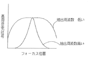
更に、フォーカス位置によってレンズの解像力は変化することがある。
図11はフォーカスの位置における解像する空間周波数が異なる例である。同図において、レンズの解像する空間周波数は無限端で3MHz、至近端では1.5MHzとする。
この場合AFのために必要な周波数特性は無限端は至近端より高いものが必要となり、至近端では無限端で必要な高い周波数特性は必要でない。至近端の必要な周波数に設定した場合は、無限端においてAF結果はピントボケが認識できてしまう場合が発生しやすい。この理由は、図6に抽出周波数が高い場合のAFの高周波成分の信号の出力とピントの位置の関係を表したように、抽出周波数の低い場合のピークの位置幅に対して抽出周波数の高い場合のピーク位置幅は狭くなるので、至近端での解像する空間周波数をもってAFの周波数特性としてもそのピークの信号が必ずしも無限端でのピーク位置とは一致しないからである。逆に無限端の必要な周波数に設定し至近端でAFを行った場合は、ボケからの応答性や合焦付近でのピーク位置検出に至近端用に設定した場合よりも時間が掛かり、安定しないといった問題が発生する。この理由は、図6に示すように信号のピークの立ち上がり方が急峻なため、空間周波数の低い至近端での空間周波数をAFの抽出周波数にするとピークから離れている場合には、空間周波数無限端に合わせてAFの周波数特性を高くしたときよりも信号変化が大きいためボケ状態からの合焦位置の検出がわかりやすく、そのため応答性が劣化するからである。また、ピーク付近の場合には、ピークの位置幅が狭いためピーク位置をオーバーシュートして安定性が欠く等の問題が発生するからである。このように、固定された所定のAF信号の周波数特性ではそれぞれについての最適な結果を得ることができない。
また、前述したようにカメラの静止画及び動画や撮像する状態、画素数、圧縮比などのカメラの撮像状態から必要なAFの解像する空間周波数が得られる場合と、レンズの焦点距離、絞り、フォーカスなどのレンズの状態から必要なAFの解像するための空間周波数特性が得られる場合とを比較し、例えばカメラの撮像状態からの周波数がレンズの状態からの必要な周波数特性よりも高い場合に、カメラの撮像状態からの周波数でAFを行ったとしてもレンズにはその高さまでの周波数数特性は必要でないだけでなく、レンズの状態からの必要な周波数特性でAFを行った場合と比較して、合焦までに時間が掛かり、安定しないといった問題が発生する。
Furthermore, the resolving power of the lens may change depending on the focus position.
FIG. 11 is an example in which the spatial frequency to be resolved at the focus position is different. In the figure, the spatial frequency resolved by the lens is 3 MHz at the infinite end and 1.5 MHz at the closest end.
In this case, the frequency characteristic required for AF needs to be higher at the infinite end than at the close end, and the high frequency characteristic required at the infinite end is not required at the close end. When set to the required frequency of the near end, if AF results it can recognize defocusing tends to occur at the infinity end. The reason for this is that, as shown in FIG. 6, the relationship between the output of the high-frequency component signal of AF when the extraction frequency is high and the focus position is high, the extraction frequency is high relative to the peak position width when the extraction frequency is low. This is because the peak position width in this case becomes narrower, and the signal of the peak does not necessarily coincide with the peak position at the infinite end even with the AF frequency characteristics having the spatial frequency to be resolved at the closest end. If you make an AF with closest end set to the required frequency of the infinity end the contrary, it takes more time than when set to a closest end to the peak position detection in the vicinity of the focal responsiveness and engagement from blurring The problem that it is not stable occurs. The reason for this is that, as shown in FIG. 6, since the signal peak rises steeply, if the spatial frequency at the close end where the spatial frequency is low is set to the AF extraction frequency , the spatial frequency is in accordance with the infinity end clarity detection of focus position from a blur state for signal change is greater than when a higher frequency characteristic of the AF, because Therefore responsiveness is deteriorated. Further, in the case of the vicinity of the peak, the peak position width is narrow, so that problems such as overshooting the peak position and lack of stability occur . As described above, it is impossible to obtain an optimum result for each of the fixed frequency characteristics of the predetermined AF signal.
In addition, as described above, when the necessary AF frequency is obtained from the camera imaging state such as the still image and moving image of the camera, the imaging state, the number of pixels, and the compression ratio, the focal length of the lens, the aperture compares the case where the spatial frequency characteristic for resolution states the necessary AF from the lens such as a focus is obtained, higher than the required frequency characteristic of the state of the frequency lens from a camera imaging state of In this case, even if AF is performed at a frequency from the imaging state of the camera, the lens does not need to have frequency characteristics up to its height, but also when AF is performed with the necessary frequency characteristics from the lens state. In comparison, there is a problem that it takes time to focus and is not stable.
以上において、装着されるレンズについてはレンズの種類やレンズの状態により解像する周波数や駆動可能な(駆動させる)最小の量が異なり、カメラについてはカメラの種類やカメラの撮影状態により解像する周波数や駆動可能な(駆動させる)最小の量が異なることを述べ、また、そのことから生じる様々な問題点について述べた。
そこで、本発明は、ピントのボケが認識できてしまう場合や、応答性が劣化し、オーバーシュートし、安定性を欠く場合に、種々の交換レンズ、そのレンズ状態及び種々のカメラとの任意の組合せ並びに任意の撮影状態(静止画又は動画、撮像する画像のサイズ、撮影画素数、撮影圧縮率、撮影画素密度、記録密度、記録画素数など)において良好な自動焦点調節を実現できる撮影装置を提供することを目的とする。
In the above, different state amount of frequency and drivable (driven thereby) minimum to resolve the type and lens For lenses in a lens that is mounted, for the camera is resolved by the photographing state of the camera type and camera The frequency and the minimum amount that can be driven (driven) are different, and various problems arising from it are described.
Therefore, the present invention can be applied to various interchangeable lenses, their lens states, and various cameras when the out-of-focus blur can be recognized, or when responsiveness deteriorates, overshoots, and lacks stability. An imaging device capable of realizing good automatic focus adjustment in any combination and any shooting state (still image or moving image, size of image to be captured, number of shooting pixels, shooting compression rate, shooting pixel density, recording density, number of recording pixels, etc.) The purpose is to provide.
上記の目的を達成するために本発明の撮影装置は、焦点調節を行うためのフォーカシング・レンズを有する交換レンズと、前記交換レンズにより結像された像を電気信号に変換する撮像素子と、前記撮像素子から得た電気信号から所定の周波数を抽出し前記抽出された電気信号に基いて前記像の合焦度を検出する合焦検出手段と、前記合焦検出手段の検出結果に基いて前記フォーカシング・レンズを駆動し焦点調節を行う焦点調節手段と、を有するカメラ部と、を有する撮像装置であって、前記交換レンズは、前記カメラ部の撮影状態から解像する空間周波数を前記カメラ部から取得し、前記カメラ部から取得した前記撮影状態から解像する空間周波数と前記交換レンズのレンズ状態における解像する空間周波数とのうち低い方の周波数に基づいて、前記フォーカシング・レンズの最小駆動量を設定する。 Imaging apparatus of the present invention to achieve the above object, an imaging device that converts the interchangeable lens and, imaged the electrical signal image by the interchangeable lens having a focusing lens for adjusting focus, and focus detection means for detecting the degree of focus of the image based on the electrical signal the extracted from the electrical signal to extract a predetermined frequency obtained from the image sensor, based on a detection result of the focus detection means an imaging apparatus having a camera unit having a focus adjustment unit that performs focus adjustment by driving the focusing lens, the interchangeable lens, the spatial frequency of resolving the shooting state of the camera unit camera Based on the lower one of the spatial frequency to be resolved from the shooting state obtained from the camera unit and the spatial frequency to be resolved in the lens state of the interchangeable lens. There are, setting the minimum amount of driving of the focusing lens.
削除 Delete
削除 Delete
削除 Delete
本発明によれば、ピントのボケが認識できてしまう場合や、応答性が劣化又はオーバーシュートにより安定性を欠く場合に、種々の交換レンズ、そのレンズ状態及び種々のカメラとの任意の組合せ並びに任意の撮影状態(静止画又は動画、撮像する画像のサイズ、撮影画素数、撮影圧縮率、撮影画素密度、記録密度、記録画素数など)において良好な自動焦点調節を実現できる。According to the present invention, when an out-of-focus blur can be recognized, or when responsiveness is deteriorated or lacks stability due to overshoot, various interchangeable lenses, their lens states, and arbitrary combinations with various cameras, and Good autofocus adjustment can be realized in any shooting state (still image or moving image, size of image to be captured, number of shooting pixels, shooting compression rate, shooting pixel density, recording density, number of recording pixels, etc.).
以下、本発明を、その実施例に基づいて説明する。 Hereinafter, the present invention will be described based on examples thereof .
図1は、本発明の一実施例の概略構成ブロック図を示す。
交換可能なレンズであるレンズ部200は、レンズマウント201a及びカメラマウント202aを介してカメラ部201に着脱される。
被写体からの光は、固定されている第1レンズ群10、変倍レンズ12、絞り14、固定されている第3レンズ群16、及び、フォーカシング・レンズ18を通って、撮像素子20の撮像面(光電変換面)に入射する。撮像素子20は、撮像面上の光学像を電気信号に変換する。撮像素子20の出力信号は、CDS回路22によりサンプル・ホールドされ、AGC回路24により所定レベルに増幅され、A/D変換器26によりディジタル信号に変換される。A/D変換器26の出力信号は、図示しないカメラ信号処理回路に供給される。
A/D変換器26の出力は、AFプリプロセス回路28に入力する。AFプリプロセス回路28は、詳細は後述するが、AF評価値を生成し、マイクロコンピュータからなるカメラ主制御回路31に供給する。主制御回路31は、AFプリプロセス回路28の出力(AF評価値)を取り込み、カメラマウント及びレンズマウントを介しレンズ主制御回路30に通信にて出力する。レンズ主制御回路30は合焦度に応じたフォーカシング速度と、AF評価値が増加するモータ駆動方向とを決定し、モータ駆動回路32を制御する。モータ駆動回路32は、主制御回路31からの指令に従ってフォーカス・モータ34を駆動し、フォーカシング・レンズ18を指定の位置に指定の速度で移動させる。これにより、AF評価値が最大になる位置に、フォーカシング・レンズ18が制御される。
レンズ主制御回路30はまた、ユーザの変倍操作に応じて、モータ駆動回路36によりズーム・モータ38を回転させ、変倍レンズ12を指定の位置まで移動させる。これにより、焦点距離を変更でき、撮影倍率が変化する。
FIG. 1 shows a schematic block diagram of an embodiment of the present invention.
A
Light from the subject passes through the fixed first lens group 10, the variable magnification lens 12, the stop 14, the fixed
The output of the A /
The lens
図2は、AFプリプロセス回路28の一例の概略構成ブロック図を示し、図3は、画面内の合焦検出領域と、合焦検出領域内の画素構成の説明図である。1フレーム又は1フィールドの画面54内に合焦検出領域56が設定される。合焦検出領域56は複数の水平ライン58からなり、各水平ライン58は複数の画素60からなる。
図2に基づいて説明する。ライン・メモリ40はA/D変換器26の出力データから、合焦検出領域56の1水平ラインの画素データP0,P1,・・・,Pnを記憶する。離散コサイン変換(DCT)回路42はライン・メモリ40に記憶される1水平ラインの画像データを直交変換し、周波数領域データF0,F1,・・・,Fnを出力する。重み付け回路44は、DCT回路42の出力に、各周波数成分がほぼ均一のレベルになるように予め決められた定数K0〜Knを乗算する。即ち、重み付け回路44は、k0×P0、K1×P1、・・・及びKn×Pnを出力する。
所定周波数成分抽出回路46は重み付け回路44の出力k0×P0、K1×P1、・・・及びKn×Pnから、主制御回路30により指令される成分のみを抽出して出力する。ライン・ピーク・ホールド回路48は、所定周波数成分抽出回路46から出力される1ライン分の出力の内の最大値をホールドし、1水平ライン毎にホールド値を次の水平ラインの最大値で更新する。
加算器50及びレジスタ52はアキュムレータを構成している。このアキュムレータは垂直方向の積分回路として機能し、ライン・ピーク・ホールド回路48の出力を累積加算する。即ち、当初、レジスタ52にはゼロをセットしておく。そして、加算器50はライン・ピーク・ホールド回路48の出力にレジスタ52の出力を加算し、加算結果をレジスタ52に書き込む。これを合焦検出領域56の全水平ライン58について実行することで、合焦検出領域の全水平ライン58の所定周波数成分の最大値の累積値がレジスタ52に格納される。レジスタ52の記憶値が、AF評価値として主制御回路30に供給される。
FIG. 2 shows a schematic block diagram of an example of the
This will be described with reference to FIG. The
The predetermined frequency
The
図4は、ライン・メモリ40、DCT回路42、重み付け回路46及び所定周波数成分抽出回路46におけるデータの変遷の一例を示す。図4(a)はライン・メモリ40に格納されるデータ列、同(b)はDCT回路42から出力されるデータ列、図4(c)は重み付け回路42の出力データ列を示す。
図4(d),(e)及び(f)は、所定周波数成分抽出回路46の出力例である。DCT回路42の出力F0〜Fnでは、F0が直流成分付近の最も低い周波数成分で、F1,F2,・・・の順で徐々に周波数が高くなり、Fnが最も高い周波数成分になる。
カメラ主制御回路31はレンズ主制御回路30に通信でカメラの識別信号を送る。これはあらかじめ決めてある番号やカメラのスペックを表すものなど識別可能な情報であればよい。カメラ主制御回路30はレンズ主制御回路31の通信からレンズの識別信号を得る。
本発明では、カメラはAFのための信号をレンズに送信する際この識別信号によってその内容を変更することができる。本実施例において映像信号からの抽出する周波数特性を変更してレンズに送信する場合について説明する。
例えば、交換可能でAFを行なうレンズが複数種類あり、それらにおいてAFの方式が異なる場合にそれぞれに合ったAF信号があらかじめ分かっている場合は、レンズの識別情報からそれぞれに合わせた信号を出力するのである。これによりどの組合せでも良好なAFを実現できる。
FIG. 4 shows an example of data transition in the
4D, 4E, and 4F are output examples of the predetermined frequency
The camera
In the present invention, when the camera transmits a signal for AF to the lens, the contents can be changed by the identification signal. It will be described to be transmitted to the lens by changing the frequency characteristic for extracting from the video signal in the present embodiment.
For example, interchangeable lens to perform AF is Ri plural kinds Ah, if the AF signal suitable for each if the AF method is different in they are known in advance, outputs the signal to suit each from the identification information of the lens To do. Thus any combination can achieve a good AF.
図12にフローを示す。S1201においてカメラ主制御回路31はレンズに識別情報を送信する。S1202においてカメラの識別情報からAF時の駆動量を判定し、S1203において決定する。
この機能により、AFを行なう際に映像信号からの抽出する周波数が異なる場合でも容易に対応することができ、良好なAFが行なえる。即ち、前出の問題(抽出する周波数が低い場合は図6のように合焦のピーク付近での信号変化が少ないためピーク位置の検出が行いにくくボケが残りやすい。一方、抽出する周波数が高い場合はボケ時の信号変化が少ないためボケからの応答性が鈍くなってしまうといった問題)は、どのカメラとレンズ組合せに対しても本実施例によって解決できる。
FIG. 12 shows the flow. In S1201, the camera
With this function, even when the frequency extracted from the video signal is different when performing AF, it is possible to easily cope with it, and good AF can be performed. That is, the above problem (when the frequency to be extracted is low, the signal position in the vicinity of the focus peak is small as shown in FIG. 6 so that it is difficult to detect the peak position and blur is likely to remain. On the other hand, the frequency to be extracted is high. In this case, the problem that the response from blurring becomes dull because the signal change at the time of blurring is small can be solved by this embodiment for any camera and lens combination.
次に、本発明の実施例2について説明する。
本実施例はレンズの状態と撮影の状態を加味し、解像する空間周波数を求め映像信号からの抽出する高周波成分の帯域を求めるものである。
図13に示されるように、撮影状態検出手段87は、静止画及び動画、撮像する画像のサイズ、画素数、圧縮率、画素密度などの撮影状態を検出し、それぞれの撮影状態はカメラ主制御回路30に入力される。また、レンズの状態はレンズ主制御回路31に入力される。例えば同じレンズ、撮像手段であっても、レンズの状態や撮影モード、圧縮率により、解像可能な空間周波数も異なってくる。撮影の状態が静止画200万画素、圧縮無しで、解像する空間周波数が10MHzとしても、レンズの状態がテレ端無限F8の場合に解像する空間周波数が0.5MHzであるとすると、AFのための映像信号の抽出する周波数は0.5MHzでよい。空間周波数が高く、抽出する周波数を高くすると合焦ピーク付近以外では信号の変化が少ないためボケ時の合焦方向が見つけにくいなどの問題があり、一方、AFのための映像信号の抽出する高周波成分の周波数帯域は低いほうが応答性がよくなるので、抽出周波数はあまり高く設定すべきではないからである。
従って、レンズが駆動すべき最小の分解能は0.5MHzでの分解能でよいことになる。駆動ピッチについては、絞りなどの状態で焦点深度が深いほど駆動量は多くなるので駆動ピッチを細かくする必要はないが、開放付近などで深度が浅い場合には単位駆動当たりのピント変化が大きくなるため駆動ピッチを細かくする。従って、最小駆動量はレンズが開放のときにその精度が求められることになる。また、解像する空間周波数が低いときは必要以上に細かくすべきではなく相応の細かさがあれば足りる。AF性能からも、解像する空間周波数から映像信号の高周波成分の抽出する周波数を変更する場合、ピークでの停止が行なえず、山の途中で止まるといった前述の問題もあるからである。このように、最小駆動ピッチと前記抽出する周波数はAFを行う際に合わせて決めておくことが必要である。これは本発明の主旨でもある。
即ち、解像する空間周波数は、レンズの特性及び撮像の状態を加味して求めることにより、どのような撮像手段におけるカメラでも、また、どのような光学情報を持つレンズとの組合せにおいても、常に最適なAFが行えるようにすることができる。
Next, a second embodiment of the present invention will be described.
In this embodiment , taking into account the state of the lens and the state of shooting, the spatial frequency to be resolved is obtained and the band of the high frequency component extracted from the video signal is obtained.
As shown in FIG. 13, the shooting state detection unit 87 detects shooting states such as still images and moving images, the size of captured images, the number of pixels, the compression rate, and the pixel density, and each shooting state is controlled by the camera main control. Input to the
Therefore, the minimum resolution to be driven by the lens may be 0.5 MHz. For driving the pitch need not be finely driving pitch since the focal depth is deep enough driving amount increases in a state such as diaphragm, focus change per unit driving becomes large when the depth or the like around the opening is shallow Therefore, the drive pitch is made fine. Therefore, the accuracy of the minimum driving amount is required when the lens is opened. In addition, when the spatial frequency to be resolved is low, it should not be made finer than necessary, and it should be fine enough . This is also because the AF performance has the above-described problem that when the frequency at which the high-frequency component of the video signal is extracted is changed from the spatial frequency to be resolved , the peak cannot be stopped and stopped in the middle of the mountain. Thus, it is necessary to determine the minimum drive pitch and the extracted frequency in accordance with AF. This is also the gist of the present invention.
That is, the spatial frequency to be resolved, by obtaining in consideration of characteristics and conditions of the imaging lens, in the camera in any imaging means, also in combination with a lens having any optical information, always it is possible to allow the optimum AF.
主制御回路30及び31は空間周波数検出機能及び抽出周波数判定機能を有し、図14、図15に示すように内蔵するROM30a、31a等に抽出周波数判定データを保有している。主制御回路30及び31は、撮像状態及びレンズ状態から内蔵ROM30a,31a等に記憶される抽出周波数判定データに従って、どの帯域の周波数成分データを抽出させるかを所定周波数成分抽出回路46に決定させる。
例えばカメラがレンズからの指示により抽出周波数を決定する場合について、図16のフローを用いて説明する。
S1601においてカメラは撮影状態を読み込み、S1602において、解像する空間周波数又は、映像信号から抽出すべき周波数をレンズに送信し、S1603においてレンズはレンズの状態を読み込み、S1604においてS1604から得られる解像する空間周波数とS1604から得られる映像信号から抽出する周波数とを比較し、S1605においてそれらの低いほうを抽出する周波数としてカメラに指示し、S1606においてカメラはその指示に従って信号を得る。S1607でレンズは求められた解像する空間周波数から最小駆動量を求め、レンズのF値の状態を加味してAFの駆動量を決定する。
The
For example, for the case where the camera determines the extraction frequency in accordance with an instruction from the lens, it will be described with reference to the flowchart of FIG. 16.
In S1601, the camera reads the shooting state. In S1602, the spatial frequency to be resolved or the frequency to be extracted from the video signal is transmitted to the lens. In S1603, the lens reads the lens state. In S1604, the resolution obtained from S1604. to compare the frequency to be extracted from a video signal obtained from the spatial frequency and S1604, instructs the camera as a frequency to extract the lower of them in S1605, the camera Ru obtain a signal according to the instruction at S1606. In step S1607, the lens obtains the minimum driving amount from the obtained spatial frequency to be resolved, and determines the AF driving amount in consideration of the F value state of the lens.
また、カメラはレンズからレンズ情報を得てもよい。レンズからレンズ情報を得る場合について図17のフローで説明する。S1701においてレンズ主制御回路31はレンズ状態を読み込み、S1702においてレンズ状態における解像する空間周波数又は映像信号からの抽出する周波数を検出し、S1703においてカメラ主制御回路30に送信し、S1704においてカメラ主制御回路30は撮影状態を読み込み、S1705において撮影状態から解像する空間周波数又は映像信号から抽出する周波数を検出し、S1703で得たレンズ状態からの情報と比較し、S1706においてそれらの低いものを抽出する周波数として信号を得る。
In addition, the camera but it may also be to obtain a lens information from the lens. For the case of obtaining the lens information from the lens that describes a flow of Figure 17. Lens
また、自動合焦手段はカメラ内部にあり、速度と方向、駆動量といったAF駆動情報をレンズに通信し、AFを行なう、いわゆる一眼レフタイプのカメラにおいても容易に応用できる。図18のフローで、これについて説明する。
S1801においてレンズ主制御回路31はレンズ状態を読み込み、S1802においてレンズ状態における解像する空間周波数または映像信号からの抽出する周波数情報を検出し、S1803においてカメラ主制御回路30に送信し、S1804においてカメラ主制御回路30は撮影状態を読み込み、S1805において撮影状態から解像する空間周波数または映像信号から抽出する周波数を検出してS1803で得たレンズ状態からの情報と比較し、S1806においてそれらの低いものを抽出する周波数として信号を得てAFを行う。
図16―18のいずれの場合も、抽出周波数判定データはレンズ情報と撮影状態における解像する空間周波数を含み、空間周波数検出機能及び抽出周波数判定機能を有しており、現在の撮影状態から解像する空間周波数を検出し、これらの検出情報から解像する1の周波数を求め、その周波数を含む帯域を選択するように所定周波数成分抽出回路46に出力する。選択する周波数帯域はこのレンズの空間周波数そのものでも構わない。上限下限を超える場合は、上限値又は下限値に設定するのはいうまでもない。
例えば、レンズ情報からワイド端・F8・無限端、撮影状態が動画,NTSCの場合、レンズ情報からは5MHz、撮像状態からは3MHzと得られるとすると、3MHz<5MHzなので、解像する周波数は3MHzと求められる。この場合は、抽出する周波数帯域を3MHzと所定周波数成分抽出回路46に指示する。このときの解像する空間周波数は解像する限界の周波数ではなく、MTFの十分な周波数であり、例えば解像限界周波数の80%程度のものである。
そうすることにより以上の例では、レンズ情報+撮像状態においてのAF結果は撮像状態のみの解像する空間周波数よりも低い周波数帯域でのAFでなく、レンズ情報+撮像情報の解像する空間周波数にあわせているためピントボケが認識できてしまうという不都合がなくなる。
Further, the automatic focusing means can be easily applied to a so-called single-lens reflex type camera that performs AF by communicating AF driving information such as speed, direction, and driving amount to the lens. This will be described with reference to the flow of FIG.
Lens
16-18 , the extracted frequency determination data includes the lens information and the spatial frequency to be resolved in the shooting state , and has a spatial frequency detection function and an extraction frequency determination function. A spatial frequency to be imaged is detected , one frequency to be resolved is obtained from the detected information , and the frequency is extracted and output to the predetermined frequency
For example , if the lens information is wide end / F8 / infinite end, the shooting state is moving image, NTSC, and if 5 MHz is obtained from the lens information and 3 MHz is obtained from the imaging state, the resolution frequency is 3 MHz because 3 MHz <5 MHz. Is required. In this case, to indicate the frequency band to be extracted 3MHz and predetermined frequency
In the example described above so doing, AF result of the lens information + image pickup state is not AF in a frequency band lower than the spatial frequency to be resolved in the imaging state only spatial frequencies resolution of lens information + imaging information Therefore, there is no inconvenience that the out-of-focus can be recognized.
10 第1レンズ群 12 変倍レンズ 14 絞り、
16 第3レンズ群 18、フォーカシング・レンズ 20 撮像素子
22 CDS回路 24 AGC回路 26 A/D変換器
28 AFプリプロセス回路 30 レンズ主制御回路
31 カメラ主制御回路 200 レンズ部 201a レンズマウント
201 カメラ部 202a カメラマウント
10 First lens group 12 Variable magnification lens 14 Aperture,
16
Claims (4)
前記交換レンズにより結像された像を電気信号に変換する撮像素子と、前記撮像素子から得た電気信号から所定の周波数を抽出し前記抽出された電気信号に基いて前記像の合焦度を検出する合焦検出手段と、前記合焦検出手段の検出結果に基いて前記フォーカシング・レンズを駆動し焦点調節を行う焦点調節手段と、を有するカメラ部と、を有する撮像装置であって、
前記交換レンズは、前記カメラ部の撮影状態から解像する空間周波数を前記カメラ部から取得し、前記カメラ部から取得した前記撮影状態から解像する空間周波数と前記交換レンズのレンズ状態における解像する空間周波数とのうち低い方の周波数に基づいて、前記フォーカシング・レンズの最小駆動量を設定することを特徴とする撮影装置。 An interchangeable lens having a focusing lens for performing focus adjustment ;
An imaging element that converts an image formed by the interchangeable lens to electrical signals, if the image based on the electrical signal the extracted from the electrical signal to extract a predetermined frequency obtained from the image sensor degree an imaging apparatus comprising: a focus detecting means for detecting, and a camera unit having a focus adjustment unit that performs focus adjustment by driving the focusing lens based on a detection result of the focus detection means,
The interchangeable lens acquires a spatial frequency resolved from the shooting state of the camera unit from the camera unit, and resolves the spatial frequency resolved from the shooting state acquired from the camera unit and the lens state of the interchangeable lens. based on the frequency of the lower of the spatial frequency, imaging device according to feature to set the minimum amount of driving of the focusing lens.
前記交換レンズにより結像された像を電気信号に変換する撮像素子と、前記撮像素子から得た電気信号から所定の周波数を抽出し前記抽出された電気信号に基いて前記像の合焦度を検出する合焦検出手段と、前記合焦検出手段の検出結果に基いて前記フォーカシング・レンズを駆動し焦点調節を行う焦点調節手段と、を有するカメラ部と、を有する撮像装置であって、An image sensor that converts an image formed by the interchangeable lens into an electric signal, and a predetermined frequency is extracted from the electric signal obtained from the image sensor, and the degree of focus of the image is determined based on the extracted electric signal. An imaging apparatus comprising: a focus detection unit that detects; and a camera unit that includes a focus adjustment unit that drives the focusing lens and performs focus adjustment based on a detection result of the focus detection unit,
前記交換レンズは、映像信号から抽出する周波数を前記カメラ部から取得し、前記カメラ部から取得した前記映像信号から抽出する周波数と前記交換レンズのレンズ状態における解像する空間周波数とのうち低い方の周波数に基づいて、前記フォーカシング・レンズの最小駆動量を設定することを特徴とする撮影装置。The interchangeable lens acquires the frequency extracted from the video signal from the camera unit, and the lower one of the frequency extracted from the video signal acquired from the camera unit and the spatial frequency to be resolved in the lens state of the interchangeable lens An imaging device, wherein a minimum driving amount of the focusing lens is set based on the frequency of the focusing lens.
前記交換レンズにより結像された像を電気信号に変換する撮像素子と、前記撮像素子から得た電気信号から所定の周波数を抽出し前記抽出された電気信号に基いて前記像の合焦度を検出する合焦検出手段と、前記合焦検出手段の検出結果に基いて前記フォーカシング・レンズを駆動し焦点調節を行う焦点調節手段と、を有するカメラ部と、を有する撮像装置であって、
前記カメラ部は、前記交換レンズのレンズ状態における解像する空間周波数を前記交換レンズから取得し、前記交換レンズから取得した前記レンズ状態における解像する空間周波数と前記カメラ部の撮影状態から解像する空間周波数とのうち低い方の周波数に基づいて、前記フォーカシング・レンズの最小駆動量を設定することを特徴とする撮影装置。 An interchangeable lens having a focusing lens for performing focus adjustment;
An image sensor that converts an image formed by the interchangeable lens into an electric signal, and a predetermined frequency is extracted from the electric signal obtained from the image sensor, and the degree of focus of the image is determined based on the extracted electric signal. An imaging apparatus comprising: a focus detection unit that detects; and a camera unit that includes a focus adjustment unit that drives the focusing lens and performs focus adjustment based on a detection result of the focus detection unit,
The camera unit obtains a spatial frequency to be resolved in the lens state of the interchangeable lens from the interchangeable lens, and resolves from the spatial frequency to be resolved in the lens state obtained from the interchangeable lens and the photographing state of the camera unit. An imaging device, wherein a minimum driving amount of the focusing lens is set based on a lower one of the spatial frequencies to be operated.
前記交換レンズにより結像された像を電気信号に変換する撮像素子と、前記撮像素子から得た電気信号から所定の周波数を抽出し前記抽出された電気信号に基いて前記像の合焦度を検出する合焦検出手段と、前記合焦検出手段の検出結果に基いて前記フォーカシング・レンズを駆動し焦点調節を行う焦点調節手段と、を有するカメラ部と、を有する撮像装置であって、An image sensor that converts an image formed by the interchangeable lens into an electric signal, and a predetermined frequency is extracted from the electric signal obtained from the image sensor, and the degree of focus of the image is determined based on the extracted electric signal. An imaging apparatus comprising: a focus detection unit that detects; and a camera unit that includes a focus adjustment unit that drives the focusing lens and performs focus adjustment based on a detection result of the focus detection unit,
前記カメラ部は、前記交換レンズのレンズ状態における解像する空間周波数を前記交換レンズから取得し、前記交換レンズから取得した前記レンズ状態における解像する空間周波数と映像信号から抽出する周波数とのうち低い方の周波数に基づいて、前記フォーカシング・レンズの最小駆動量を設定することを特徴とする撮影装置。The camera unit acquires a spatial frequency to be resolved in the lens state of the interchangeable lens from the interchangeable lens, and out of a spatial frequency to be resolved in the lens state obtained from the interchangeable lens and a frequency extracted from a video signal An imaging apparatus, wherein a minimum driving amount of the focusing lens is set based on a lower frequency.
Priority Applications (1)
| Application Number | Priority Date | Filing Date | Title |
|---|---|---|---|
| JP2004371802A JP4574345B2 (en) | 2004-12-22 | 2004-12-22 | Imaging device |
Applications Claiming Priority (1)
| Application Number | Priority Date | Filing Date | Title |
|---|---|---|---|
| JP2004371802A JP4574345B2 (en) | 2004-12-22 | 2004-12-22 | Imaging device |
Publications (3)
| Publication Number | Publication Date |
|---|---|
| JP2006178211A JP2006178211A (en) | 2006-07-06 |
| JP2006178211A5 JP2006178211A5 (en) | 2008-02-21 |
| JP4574345B2 true JP4574345B2 (en) | 2010-11-04 |
Family
ID=36732380
Family Applications (1)
| Application Number | Title | Priority Date | Filing Date |
|---|---|---|---|
| JP2004371802A Expired - Fee Related JP4574345B2 (en) | 2004-12-22 | 2004-12-22 | Imaging device |
Country Status (1)
| Country | Link |
|---|---|
| JP (1) | JP4574345B2 (en) |
Families Citing this family (3)
| Publication number | Priority date | Publication date | Assignee | Title |
|---|---|---|---|---|
| JP5087077B2 (en) * | 2007-08-29 | 2012-11-28 | パナソニック株式会社 | Interchangeable lens camera system with autofocus function |
| JP2012234152A (en) * | 2011-04-19 | 2012-11-29 | Canon Inc | Imaging apparatus and control method thereof |
| EP3789811B1 (en) * | 2019-06-27 | 2022-09-07 | Panasonic Intellectual Property Management Co., Ltd. | Imaging device |
Citations (4)
| Publication number | Priority date | Publication date | Assignee | Title |
|---|---|---|---|---|
| JP2001075005A (en) * | 1999-09-06 | 2001-03-23 | Canon Inc | Optical equipment, method for controlling it and memory medium |
| JP2001352481A (en) * | 2000-06-08 | 2001-12-21 | Canon Inc | Imaging device |
| JP2004191814A (en) * | 2002-12-13 | 2004-07-08 | Canon Inc | Autofocus device |
| JP2004258088A (en) * | 2003-02-24 | 2004-09-16 | Fuji Photo Optical Co Ltd | Autofocus system |
-
2004
- 2004-12-22 JP JP2004371802A patent/JP4574345B2/en not_active Expired - Fee Related
Patent Citations (4)
| Publication number | Priority date | Publication date | Assignee | Title |
|---|---|---|---|---|
| JP2001075005A (en) * | 1999-09-06 | 2001-03-23 | Canon Inc | Optical equipment, method for controlling it and memory medium |
| JP2001352481A (en) * | 2000-06-08 | 2001-12-21 | Canon Inc | Imaging device |
| JP2004191814A (en) * | 2002-12-13 | 2004-07-08 | Canon Inc | Autofocus device |
| JP2004258088A (en) * | 2003-02-24 | 2004-09-16 | Fuji Photo Optical Co Ltd | Autofocus system |
Also Published As
| Publication number | Publication date |
|---|---|
| JP2006178211A (en) | 2006-07-06 |
Similar Documents
| Publication | Publication Date | Title |
|---|---|---|
| US7916182B2 (en) | Imaging device and method which performs face recognition during a timer delay | |
| KR100859892B1 (en) | Optical apparatus | |
| JP4127491B2 (en) | Camera with auto focus function | |
| JP2006258944A (en) | Autofocus system | |
| JP5294647B2 (en) | Focus adjustment apparatus and control method thereof | |
| JP2008175995A (en) | Imaging apparatus | |
| JP2010139666A (en) | Imaging device | |
| JP4645413B2 (en) | Imaging device | |
| EP1672913B1 (en) | Image pickup apparatus | |
| JP2005338352A (en) | Autofocus system | |
| JP4596246B2 (en) | Auto focus system | |
| US6333761B2 (en) | Image pickup apparatus having focus detection area size dependent on aspect ratio | |
| JP5335408B2 (en) | Focus adjustment apparatus and method | |
| US8928799B2 (en) | Imaging device and imaging method to perform autofocus operation to a subject | |
| JP2957800B2 (en) | Automatic focusing device | |
| JP2015106116A (en) | Imaging apparatus | |
| US20150226934A1 (en) | Focus adjustment apparatus having frame-out preventive control, and control method therefor | |
| JP5075110B2 (en) | Focus adjustment apparatus and method | |
| JP2006215391A (en) | Autofocus system | |
| JP4574345B2 (en) | Imaging device | |
| JP2006178211A5 (en) | ||
| JP4612814B2 (en) | Automatic focusing apparatus, control method therefor, and imaging apparatus | |
| JP2006171470A (en) | Photographing apparatus | |
| JP2006162943A (en) | Automatic focusing control method and automatic focusing controller | |
| KR100650955B1 (en) | Method and apparatus for adjusting auto focus |
Legal Events
| Date | Code | Title | Description |
|---|---|---|---|
| A521 | Request for written amendment filed |
Free format text: JAPANESE INTERMEDIATE CODE: A523 Effective date: 20071221 |
|
| A621 | Written request for application examination |
Free format text: JAPANESE INTERMEDIATE CODE: A621 Effective date: 20071221 |
|
| A521 | Request for written amendment filed |
Free format text: JAPANESE INTERMEDIATE CODE: A523 Effective date: 20080116 |
|
| RD01 | Notification of change of attorney |
Free format text: JAPANESE INTERMEDIATE CODE: A7421 Effective date: 20090406 |
|
| RD04 | Notification of resignation of power of attorney |
Free format text: JAPANESE INTERMEDIATE CODE: A7424 Effective date: 20100201 |
|
| A131 | Notification of reasons for refusal |
Free format text: JAPANESE INTERMEDIATE CODE: A131 Effective date: 20100518 |
|
| A521 | Request for written amendment filed |
Free format text: JAPANESE INTERMEDIATE CODE: A523 Effective date: 20100629 |
|
| RD01 | Notification of change of attorney |
Free format text: JAPANESE INTERMEDIATE CODE: A7421 Effective date: 20100630 |
|
| TRDD | Decision of grant or rejection written | ||
| A01 | Written decision to grant a patent or to grant a registration (utility model) |
Free format text: JAPANESE INTERMEDIATE CODE: A01 Effective date: 20100817 |
|
| A01 | Written decision to grant a patent or to grant a registration (utility model) |
Free format text: JAPANESE INTERMEDIATE CODE: A01 |
|
| A61 | First payment of annual fees (during grant procedure) |
Free format text: JAPANESE INTERMEDIATE CODE: A61 Effective date: 20100818 |
|
| R150 | Certificate of patent or registration of utility model |
Free format text: JAPANESE INTERMEDIATE CODE: R150 |
|
| FPAY | Renewal fee payment (event date is renewal date of database) |
Free format text: PAYMENT UNTIL: 20130827 Year of fee payment: 3 |
|
| LAPS | Cancellation because of no payment of annual fees |