JP4572033B2 - Spinning reel rotor - Google Patents
Spinning reel rotor Download PDFInfo
- Publication number
- JP4572033B2 JP4572033B2 JP2000385193A JP2000385193A JP4572033B2 JP 4572033 B2 JP4572033 B2 JP 4572033B2 JP 2000385193 A JP2000385193 A JP 2000385193A JP 2000385193 A JP2000385193 A JP 2000385193A JP 4572033 B2 JP4572033 B2 JP 4572033B2
- Authority
- JP
- Japan
- Prior art keywords
- rotor
- cylindrical portion
- spool
- spinning reel
- inertia
- Prior art date
- Legal status (The legal status is an assumption and is not a legal conclusion. Google has not performed a legal analysis and makes no representation as to the accuracy of the status listed.)
- Expired - Fee Related
Links
Images


Description
【0001】
【発明の属する技術分野】
本発明は、ロータ、特に、スピニングリールのリール本体に回転自在に装着され、糸巻き用のスプールに釣り糸を巻き付けるためのスピニングリールのロータに関する。
【0002】
【従来の技術】
一般に、スピニングリールは、釣り竿に装着されるリール本体と、リール本体の前部に前後移動自在に装着された糸巻用のスプールと、リール本体に回転自在に装着され釣り糸をスプールに巻き付けるためのロータとを備えている。ロータは、スプールの内周側に配置される円筒部と、円筒部の後端部から前方に延びる第1及び第2アーム部と、両アーム部の先端に揺動自在に装着され釣り糸をスプールに巻き付けるベールアームとを有している。
【0003】
この種のスピニングリールのロータは、最近、アルミニウム合金やマグネシウム合金などの軽金属で製作され軽量化が図られている。
【0004】
【発明が解決しようとする課題】
前記従来の軽量化が図られたロータでは、慣性モーメントが小さくなるため、回転開始時(起動時)にロータが軽く回り始める。しかし、ロータに作用する負荷が小さい場合、ハンドルを回す手の力加減によって容易に回転速度が変化し、滑らかさに欠けて回転フィーリングが低下するという問題がある。これを防止するために、慣性力を単純に増加させるだけでは、ロータの起動に要するエネルギーが増加し、起動時の効率が損なわれる。
【0005】
本発明の課題は、軽量化を図ったロータであっても、回転フィーリングを重視する場合と、起動時の効率を重視する場合とで使い分けることができるようにすることにある。
【0006】
【課題を解決するための手段】
発明1に係るスピニングリールのロータは、スピニングリールのリール本体に回転自在に装着されるピニオンギアにナットにより固定され、糸巻き用のスプールに釣り糸を巻き付けるためのものであって、ロータ本体と、ベールアームと、慣性付与部材とを備えている。ロータ本体は、リール本体に回転自在に装着される円筒部と、円筒部の後端部から前方に延びる第1及び第2アーム部とを有している。ベールアームは、両アーム部の先端に揺動自在に装着されスプールに釣り糸を案内するものである。慣性付与部材は、ナットの外周側においてナットと離反して配置され、ロータ本体の前壁より前方でロータ本体に着脱自在に固定される部材である。
【0007】
このロータでは、ロータ本体に慣性付与部材が着脱自在に装着される。ここで、回転フィーリングを重視する場合には、慣性付与部材をロータ本体に装着する。すると、ロータの慣性モーメントが増加するので、回転フィーリングが損なわれにくくなる。また、起動時の効率を重視する場合には、慣性付与部材をロータ本体から外す。これにより、ロータの起動時にロータが軽く回り始め、起動時の効率を高く維持できる。ここでは、慣性付与部材をロータ本体に対して着脱自在にしたので、回転フィーリングを重視する場合には、慣性付与部材を装着し、起動時の効率を重視する場合には外せばよい。このため、ロータの軽量化を図っても、前記2つの場合で使い分けすることができる。
【0008】
発明2に係るスピニングリールのロータは、発明1に記載のロータにおいて、慣性付与部材は、ロータ本体にねじにより固定されるリング状の部材である。この場合には、慣性付与部材がリング状であるので、ロータの回転軸芯と同芯に配置することにより回転バランスが損なわれにくくなる。
【0009】
発明3に係るスピニングリールのロータは、発明1又は2に記載のロータにおいて、慣性付与部材は、ロータ本体の円筒部に着脱自在に装着される。この場合には、スプールの内側に配置されるロータの円筒部に慣性付与部材が配置されるので、慣性付与部材を装着しても邪魔にならない。
【0010】
発明4にかかるスピニングリールのロータは、発明3に記載のロータにおいて、円筒部は、リール本体に回転自在に装着される前壁を有し、慣性付与部材は前壁に円筒部と同芯に配置されている。この場合には、慣性付与部材が円筒部と同芯に配置されているので、慣性付与部材を装着しても回転バランスが損なわれにくくなる。
【0011】
発明5に係るスピニングリールのロータは、発明1から4のいずれかに記載のロータにおいて、スプールは円筒部の外周側に隙間をあけて配置される筒状のスカート部を有し、慣性付与部材は、円筒部とスカート部との隙間からの釣り糸の進入を防止する。この場合には、慣性付与部材によってスプールとロータとの隙間を小さくすることにより、円筒部とスカート部との隙間からの釣り糸の進入を防止でき、釣り糸がスプール軸に絡みにくくなる。
【0012】
発明6に係るスピニングリールのロータは、発明1から5のいずれかに記載のロータにおいて、慣性付与部材は、ロータ本体より比重が大きい材料で形成されている。この場合には、小さな容積で慣性モーメントを大きく増加させることができる。
【0013】
【発明の実施の形態】
〔全体構成〕
図1において、本発明の一実施形態を採用したスピニングリールは、釣り竿に装着可能なリール本体2と、リール本体2に左右軸回りに回転自在に装着されたハンドル組立体1と、ロータ3と、スプール4とを備えている。ロータ3は、ハンドル組立体1の回転に連動して回転して釣り糸をスプール4に案内するものであり、リール本体2の前部に前後軸回りに回転自在に支持されている。スプール4は、ロータ3により案内された釣り糸を外周面に巻き取るものであり、ロータ3の前部に前後軸方向に往復移動自在に配置されている。
【0014】
〔リール本体の構成〕
リール本体2は、図3に示すように、リール本体2の主部を構成し側部に開口2cを有するリールボディ2aと、リールボディ2aから斜め上前方に一体で延びるT字状の竿取付脚2bと、開口2cを塞ぐようにリールボディ2aにねじ止めされた蓋部材2dとを有している。
【0015】
リールボディ2aは、内部に開口2cに連なる機構装着用の空間を有しており、その空間内には、図2に示すように、ロータ3をハンドル組立体1の回転に連動して回転させるロータ駆動機構5と、スプール4を前後に移動させて釣り糸を均一に巻き取るためのオシレーティング機構6とが設けられている。
【0016】
リールボディ2aの前部には、図3に示すように、第1フランジ部2eと第1フランジ部2eから前方に突出する筒状部2fとが形成されている。第1フランジ部2eは、弦と円弧とからなる部分が欠落したような略半円形状であり、開口2cの前端に連なって形成されている。筒状部2fは円筒状の部分であり、その内部には、図2に示すように、ロータ3の糸繰り出し方向の回転(逆転)を禁止・解除するための逆転防止機構50のワンウェイクラッチ51が回転不能に装着されている。筒状部2fの後端部には他の部分より僅かに小径の断面視D字状の溝部2hが形成されており、溝部2hの後面は蓋部材2d装着部分が開口2cに連通して開放されている。
【0017】
蓋部材2dは、前端部に第1フランジ部2eの欠落部分の弦と円弧とからなる略半円形状に形成された第2フランジ部2gが一体形成されている。第2フランジ部2gの第1フランジ部2e及び筒状部2fの後面との接触面には、これらとの隙間をシールするための弾性体製の防水シール81が装着されている。防水シール81は、第2フランジ部2gの前面から後面にかけて第1フランジ部2eとの接触面と溝部2hの後面との接触面とに対向する位置に連続して略半円弧の帯状に形成されている。防水シール81は、第2フランジ部2gの前面に形成された略半円弧状の装着溝81aに装着されている。
【0018】
リール本体2の後部は、図2及び図3に示すように、たとえば、金属製又は合成樹脂製の保護カバー13により覆われている。保護カバー13は、リールボディ2a及び蓋部材2dの下部から背面さらに竿取付脚2bにかけてリール本体2の下部及び背面を覆うように配置されている。保護カバー13は、リール本体2にねじにより着脱自在に固定されている。保護カバー13とリール本体2との間には、合成樹脂製のスペーサ13aが介装されている。スペーサ13aは、保護カバー13とリール本体2との隙間を埋めるために介装されている。このようなスペーサ13aを介装させることで、保護カバー13を合成樹脂で製作しても、その製作誤差による隙間の変動を吸収することができる。
【0019】
〔ロータ駆動機構の構成〕
ロータ駆動機構5は、図2に示すように、ハンドル組立体1が回転不能に装着されたマスターギア11と、このマスターギア11に噛み合うピニオンギア12とを有している。
【0020】
マスターギア11は、フェースギアであり、マスターギア軸10と一体形成されている。マスターギア軸10は中心にハンドル組立体1が回転不能に係止される係止孔10aが形成された、たとえばステンレス製の中空の部材であり、その両端が、軸受を介してリールボディ2a及び蓋部材2dに回転自在に支持されている。
【0021】
ピニオンギア12は、筒状の部材であり前後方向に沿って配置されリールボディ2aに回転自在に装着されている。ピニオンギア12の前部12aはロータ3の中心部を貫通しており、この貫通部分でナット33によりロータ3と固定されている。ピニオンギア12は、軸方向の中間部と後端部とでそれぞれ軸受14a,14bを介してリールボディ2aに回転自在に支持されている。このピニオンギア12の内部をスプール軸15が貫通している。ピニオンギア12は、マスターギア11に噛み合うとともにオシレーティング機構6にも噛み合っている。
【0022】
〔ロータの構成〕
ロータ3は、ピニオンギア12に固定された円筒部30及び円筒部30の側方に互いに対向して設けられた第1及び第2ロータアーム31,32を有するロータ本体8と、両ロータアーム31,32の先端に揺動自在に装着され、釣り糸をスプール4に案内するためのベールアーム40とを有している。ロータ本体8の円筒部30と両ロータアーム31,32とは、たとえば軽量薄肉のアルミニウム合金製であり一体成形されている。
【0023】
図4に示すように、円筒部30の前部には前壁41が形成されており、前壁41の中心部には、後方に突出するボス部42が形成されている。このボス部42の中心部にはピニオンギア12に回転不能に係止される貫通孔が形成されており、この貫通孔をピニオンギア12の前部12a及びスプール軸15が貫通している。
【0024】
図4及び図5に示すように、前壁41の前面には、ロータ3に慣性モーメントを付与するための慣性付与リング(慣性付与部材の一例)44が着脱自在に装着されている。慣性付与リング44は、たとえばステンレス製であり、アルミニウム製のロータ3より比重が大きいものである。慣性付与リング44は、ロータ3の軽量化に伴って回転フィーリングが損なわれるのを防止するとともに、それを外すことにより起動時の効率を維持するために設けられており、ロータ3の回転バランスを考慮して円筒部30と同芯に、つまりスプール軸15と同芯に配置されている。慣性付与リング44は、2本のねじ45により前壁41に着脱自在に装着されている。
【0025】
ピニオンギア12の前部12aにはナット33が螺合しており、このナット33によりピニオンギア12の先端部にロータ3が回転不能に固定される。ナット33の内周側には、軸受35が配置されている。軸受35は、スプール軸15とピニオンギア12の内面との間に隙間を確保するために設けられている。ナット33及び軸受35の前面には、内周側にリップを有するシール部材36が装着されている。シール部材36の先端はスプール軸15に接触している。これによりスプール軸15からリール本体2の内部への液体の浸入を防止できる。ナット33は、リテーナ37により回り止めされている。リテーナ37は、ナット33を前方から覆うように袋状に形成されており、2本のねじ46により前壁41に着脱自在に装着されている。なお、リテーナ37の内部には12の角部を有する星形の穴が形成されており、ナット33の角部を30度ごとの位相で係止可能である。
【0026】
ボス部42に隣接して前述した逆転防止機構50が配置されている。逆転防止機構50は、図2に示すように、ワンウェイクラッチ51と、ワンウェイクラッチ51を作動状態(逆転禁止状態)と非作動状態(逆転許可状態)とに切り換える切換機構52とを有している。
【0027】
ワンウェイクラッチ51は、ピニオンギア12に内輪51aが回転不能に装着され、筒状部2fに外輪51bが回転不能に装着された内輪遊転型のローラ形のワンウェイクラッチである。内輪51aとロータ3のボス部42との間には、図4に示すように、ステンレス合金製の間隙部材43が介装されている。間隙部材43は、筒部43aと円板部43bとを有する薄肉円筒部材であり、筒部43aがボス部42の外周にはめ込まれ、円板部43bが内輪51aの前端面とボス部42との間に挟まれている。
【0028】
筒状部2fの内部において、ワンウェイクラッチ51の前方には、リップ付きの軸シール85が装着されている。軸シール85の先端リップは、間隙部材43の筒部43aの外周面に接触している。ここで、間隙部材43の内周側は、円板部43bがボス部42と内輪51aとに挟まれているので、液体が侵入しにくい。したがって、間隙部材43の外周面をシールすれば、筒状部2fの内部に液体が侵入しにくくなる。ここで、間隙部材43を設けたのは、軸シール85を直接ボス部42に接触させると、ロータ3をピニオンギア12に固定するとき、ロータ3の芯出しを正確に行わなければ、軸シール85とのシール性が悪くなる。そこで、間隙部材43を装着して軸シール85との芯出しを予め行うことで、軸シール85のシール性能を安定させることができる。
【0029】
切換機構52は、図2に示すようにストッパ軸53を有している。ストッパ軸53は、リールボディ2aに非作動姿勢と作動姿勢との間で揺動自在に装着されている。ストッパ軸53は、操作のためにリールボディ2a及び保護カバー13を貫通して後方に突出したストッパつまみ53aと、ストッパつまみ53aが固定された軸部53bと、軸部53bの先端に固定されたカム部53cとを有している。
【0030】
ストッパつまみ53aは、図3に示すように、六角穴付き止めねじ58により軸部53bに着脱自在に固定されている。ここで、ストッパつまみ53aを軸部53bに対して着脱自在にしたのは、蓋部材2dを外すために保護カバー13を外すときにストッパつまみ53aを外す必要があるからである。このストッパつまみ53aの固定に六角穴付き止めねじ58を使用することにより、ねじの頭部がないため、座繰り穴でねじの頭部を隠すことなく、釣り糸を引っ掛かりにくくすることができる。
【0031】
カム部53cはトグルばね機構59により非作動姿勢と作動姿勢とに振り分けて付勢されている。カム部53cの先端は、ワンウェイクラッチ51に係合し、ストッパ軸53の揺動によりワンウェイクラッチ51を非作動状態と作動状態とに切り換えるように構成されている。
【0032】
〔オシレーティング機構の構成〕
オシレーティング機構6は、図2に示すように、スプール軸15の略直下方に平行に配置された螺軸21と、螺軸21に沿って前後方向に移動するスライダ22と、螺軸21の先端に固定された中間ギア23とを有している。スライダ22は、螺軸21と平行に配置された2本のガイド軸24に移動自在に支持されている。スライダ22にはスプール軸15の後端が回転不能に固定されている。中間ギア23は、減速機構(図示せず)を介してピニオンギア12に噛み合っている。
【0033】
〔スプールの構成〕
スプール4は、図2に示すように、浅溝形のものであり、ロータ3の第1ロータアーム31と第2ロータアーム32との間に配置されている。スプール4は、スプール軸15の先端部にドラグ機構60を介して連結されている。スプール4は、外周に釣り糸が巻かれる糸巻胴部4aと、糸巻胴部4aの後部に一体で形成されたスカート部4bと、糸巻胴部4aの前端に設けられたフランジ部4cとを有している。
【0034】
糸巻胴部4aは、中心にボスを有する略2重の円筒状の部材であり、外周側の円筒部分の外周面はスプール軸15と平行な周面で構成されている。糸巻胴部4aは、図4に示すように、ボスに装着された2つの軸受56,57によりスプール軸15に回転自在に装着されている。スカート部4bは、糸巻胴部4aの後端部から径方向に拡がった後に後方に延びる有底円筒部材である。フランジ部4cは、糸巻胴部4aの前端部から径方向外方に一体的に形成された立ち上がり部4dと、立ち上がり部4dに着脱自在に装着された金属又はセラミック製のリング部4eとを有している。リング部4eは、糸巻胴部4aの内周面にねじ込まれたフランジ固定部材4fにより立ち上がり部4dに固定されている。
【0035】
スプール4は、スプール軸15に装着された位置決めワッシャ54に当接して位置決めされている。
【0036】
〔ドラグ機構の構成〕
ドラグ機構60は、スプール4とスプール軸15との間に装着されスプール4にドラグ力を作用させるための機構である。ドラグ機構60は、図4に示すように、ドラグ力を手で調整するためのつまみ部61と、つまみ部61によりスプール4側に押圧される複数枚のディスクからなる摩擦部62とを有している。
【0037】
つまみ部61は、スプール軸15に回転不能かつ軸方向移動自在に設けられた第1部材63と、第1部材63の軸方向前方に配置されスプール軸15に螺合する第2部材64と、第1部材63と第2部材64との間に装着された発音機構65とを有している。
【0038】
第1部材63は、円筒部63aと円筒部63aより大径のリング状の鍔部63bとを有する鍔付き円筒状の部材である。円筒部63aの内周部には、スプール軸15に回転不能に係止する小判形状の係止孔66が形成されている。第1部材63の円筒部63aの後端面が摩擦部62に当接する。第1部材63の円筒部63aと糸巻胴部4aの内側の円筒部分の内周面との間には、外部から摩擦部62側への液体の侵入を防止するためのシール板71が装着されている。シール板71は、たとえば、ステンレス製のリング部材の周囲にNBR製の皿状の弾性部材をアウトサート成形して得られたシール部材であり、外周部にリップを有している。シール板71は、スナップリング79により図5左方に付勢されている。シール板71の図6左側面には、リング状の突起部71cが形成されている。この突起部71cは、後述するカバー部材68に当接して内周側への液体の侵入を防止している。
【0039】
第2部材64は、第1部材63と対向しかつ第1部材63と相対回動自在に設けられている。第2部材64は、第1部材63のスプール軸15方向前方に並べて配置されたつまみ本体67と、つまみ本体67の外周部に先端が固定され第1部材63を内部に相対回動自在に収納するカバー部材68とを有している。
【0040】
つまみ本体67は円盤状の部材であり、前面に前方に突出した略台形状のつまみ67aが形成されている。つまみ本体67の内部には、スプール軸15の先端に螺合するナット69が回転不能かつ軸方向移動自在に装着されている。また、第2部材64とナット69との間においてスプール軸15の外周にはコイルばね70が圧縮状態で配置されている。
【0041】
カバー部材68は、段付き有底筒状の部材であり、その底部を第1部材63の円筒部63aが貫通している。また、底部にシール板71の突起部71cが当接している。カバー部材68の筒部68aは、つまみ本体67の外周面にネジ止めされている。
【0042】
カバー部材68の筒部68aの先端部とつまみ本体67との間にはOリング73が装着されている。Oリング73は、たとえばNBR製の弾性部材であり、第1部材63と第2部材64のつまみ本体67との隙間から内部に液体が侵入するのを防止するために設けられている。この隙間から液体が侵入すると、たとえシール板71を設けても、第1部材63とスプール軸15との隙間を通って摩擦部62まで水が侵入し、摩擦部62が濡れてドラグ力が変動することがある。
【0043】
摩擦部62は、第1部材63に接触するディスク91と、ディスク91に設けられたドラグ発音機構93とを有している。ディスク91は内円板部91aと、内円板部91aの外周側から後方に延びる円筒部91bと、円筒部91bの後端部から径方向外方に延びる外円板部91cとを有している。ディスク91は、内円板部91aがスプール軸15に係止され、スプール軸15に対して回転不能である。また、外円板部91cにドラグ発音機構93が装着されるとともに、グラファイト製のドラグディスク92を介してスプール4が接触している。ドラグ発音機構93は、スプール軸15とスプール4との相対回動時、つまりドラグ作動時に発音する。
【0044】
〔リールの操作及び動作〕
このスピニングリールでは、キャスティング時等の糸繰り出し時にはベールアーム40を糸開放姿勢に倒す。この結果、釣り糸は仕掛けの自重によりスプール4の先端側から順に繰り出される。
【0045】
糸巻取時には、ベールアーム40を糸巻取姿勢側に戻す。これは、ハンドル組立体1を糸巻取方向に回転させると、図示しないベール反転機構の働きにより自動的に行われる。ハンドル組立体1の回転力は、マスターギア軸10及びマスターギア11を介してピニオンギア12に伝達される。ピニオンギア12に伝達された回転力は、その前部12aからロータ3に伝達されるとともに減速機構を介してピニオンギア12に噛み合う中間ギア23によりオシレーティング機構6に伝達される。この結果、ロータ3が糸巻取方向に回転するとともにスプール4が前後に往復移動する。このとき、慣性付与リング44をロータ3の前壁41に装着したので、慣性モーメントが増加し、ロータ3の回転がスムーズになり、ロータ3の軽量化を図っても回転フィーリングが向上する。
【0046】
釣りを行っているときに、波などがリールにかかってリールが濡れることがある。この場合にも、シール板71やOリング73がドラグ機構60に装着されているので、摩擦部62に前部や後部から水が侵入しにくい。このため、一度ドラグ力を調整すれば、水濡れによるドラグ力の変動が生じにくい。
【0047】
また蓋部材2dとリールボディ2aとの間に防水シール81が設けられているので、内部の機構装着空間内への液体の侵入を防止することができる。このため、内部に海水等が入りにくくなり、塩の結晶がギアやガイド部分や軸受内部等で析出しにくくなる。
【0048】
〔他の実施形態〕
(a) 前記実施形態では、フロントドラグ型のスピニングリールを例に説明したが、リアドラグ型のスピニングリールやドラグを有さないスピニングリールやレバードラグ型のスピニングリール等の全てのスピニングリールのロータに本発明を適用できる。
【0049】
(b) 前記実施形態では、ロータ3の前壁41に慣性付与リング44を装着したが、円筒部30の外周面や内周面など、ロータ3のどのような部位に装着してもよい。ただし、ロータ3の回転バランスを考慮してロータ本体8と同芯に配置するのが好ましい。
【0050】
(c) 前記実施形態では、慣性付与部材としてリング状の慣性付与リングを例示した。しかし、慣性付与部材は、回転バランスがとれているものであれば、形状はどのようなものでもよいとともに、一体型ではなく分割されていてもよい。分割型の場合、たとえば8分割等に分割して、それぞれを着脱自在に構成し、慣性力を調整できるようにしてもよい。
【0051】
【発明の効果】
本発明によれば、慣性付与部材をロータ本体に対して着脱自在にしたので、回転フィーリングを重視する場合には、慣性付与部材を装着し、起動時の効率を重視する場合には外せばよい。このため、ロータの軽量化を図っても、前記2つの場合で使い分けすることができる。
【図面の簡単な説明】
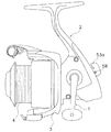
【図1】 本発明の一実施形態を採用したスピニングリールの左側面図。
【図2】 その左側面断面図。
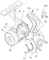
【図3】 リール本体の分解斜視図。
【図4】 スプール及びロータ中心部の断面部分図。
【図5】 ロータ前部の分解斜視図。
【符号の説明】
2 リール本体
3 ロータ
4 スプール
4b スカート部
8 ロータ本体
30 円筒部
31,32 第1及び第2ロータアーム
40 ベールアーム
41 前壁
44 慣性付与リング[0001]
BACKGROUND OF THE INVENTION
The present invention relates to a rotor, and more particularly to a spinning reel rotor that is rotatably mounted on a reel body of a spinning reel and winds a fishing line around a spool for spooling.
[0002]
[Prior art]
In general, a spinning reel includes a reel body mounted on a fishing rod, a spool for spools mounted on the front of the reel body so as to be movable back and forth, and a rotor that is rotatably mounted on the reel body and winds fishing lines around the spool. And. The rotor includes a cylindrical portion disposed on the inner peripheral side of the spool, first and second arm portions extending forward from the rear end portion of the cylindrical portion, and a swingable spool mounted on the tip of both arm portions. And a bale arm wound around.
[0003]
Recently, the rotor of this type of spinning reel is made of a light metal such as an aluminum alloy or a magnesium alloy to reduce the weight.
[0004]
[Problems to be solved by the invention]
In the conventional rotor that has been reduced in weight, the moment of inertia is reduced, so that the rotor starts to rotate lightly at the start of rotation (at the time of starting). However, when the load acting on the rotor is small, there is a problem that the rotational speed easily changes due to the force of the hand turning the handle, lacking smoothness and lowering the rotational feeling. In order to prevent this, simply increasing the inertial force increases the energy required for starting the rotor and impairs the starting efficiency.
[0005]
SUMMARY OF THE INVENTION An object of the present invention is to make it possible to use a rotor that is light in weight, depending on whether rotation feeling is important or efficiency when starting is important.
[0006]
[Means for Solving the Problems]
A spinning reel rotor according to a first aspect of the present invention is a nut fixed to a pinion gear rotatably mounted on a spinning reel reel body, and is used for winding a fishing line around a spool for spooling the rotor. An arm and an inertia imparting member are provided. The rotor body has a cylindrical portion that is rotatably mounted on the reel body, and first and second arm portions that extend forward from the rear end portion of the cylindrical portion. The bale arm is swingably attached to the ends of both arm portions and guides the fishing line to the spool. The inertia imparting member is a member that is disposed away from the nut on the outer peripheral side of the nut and is detachably fixed to the rotor body in front of the front wall of the rotor body.
[0007]
In this rotor, the inertia imparting member is detachably attached to the rotor body. Here, when importance is attached to the rotational feeling, the inertia imparting member is attached to the rotor body. Then, since the moment of inertia of the rotor increases, the rotational feeling becomes difficult to be impaired. Further, when importance is placed on the efficiency at the time of startup, the inertia imparting member is removed from the rotor body. Thereby, the rotor starts to rotate lightly at the time of starting the rotor, and the efficiency at the time of starting can be maintained high. Here, since the inertia imparting member is detachable from the rotor body, the inertia imparting member is attached when importance is attached to the rotational feeling, and the inertia imparting member is removed when importance is placed on the efficiency at the time of startup. For this reason, even if the weight of the rotor is reduced, it can be used properly in the above two cases.
[0008]
A spinning reel rotor according to a second aspect of the present invention is the rotor according to the first aspect, wherein the inertia imparting member is a ring-shaped member that is fixed to the rotor main body with a screw . In this case, since the inertia imparting member has a ring shape, the rotational balance is hardly impaired by being arranged concentrically with the rotational axis of the rotor.
[0009]
A spinning reel rotor according to a third aspect is the rotor according to the first or second aspect, wherein the inertia imparting member is detachably attached to the cylindrical portion of the rotor body. In this case, since the inertia imparting member is disposed in the cylindrical portion of the rotor disposed on the inner side of the spool, even if the inertia imparting member is attached, it does not get in the way.
[0010]
A spinning reel rotor according to a fourth aspect of the invention is the rotor according to the third aspect, wherein the cylindrical portion has a front wall rotatably mounted on the reel body, and the inertia imparting member is concentric with the cylindrical portion on the front wall. Has been placed. In this case, since the inertia imparting member is disposed concentrically with the cylindrical portion, even if the inertia imparting member is attached, the rotational balance is not easily lost.
[0011]
A spinning reel rotor according to a fifth aspect of the present invention is the rotor according to any one of the first to fourth aspects, wherein the spool has a cylindrical skirt portion arranged with a gap on the outer peripheral side of the cylindrical portion, and an inertia imparting member Prevents the fishing line from entering from the gap between the cylindrical portion and the skirt portion. In this case, by reducing the clearance between the spool and the rotor by the inertia imparting member, the fishing line can be prevented from entering from the clearance between the cylindrical portion and the skirt portion, and the fishing line is less likely to be entangled with the spool shaft.
[0012]
A spinning reel rotor according to a sixth aspect of the present invention is the rotor according to any one of the first to fifth aspects, wherein the inertia imparting member is made of a material having a specific gravity greater than that of the rotor body. In this case, the moment of inertia can be greatly increased with a small volume.
[0013]
DETAILED DESCRIPTION OF THE INVENTION
〔overall structure〕
In FIG. 1, a spinning reel employing an embodiment of the present invention includes a
[0014]
[Reel body configuration]
As shown in FIG. 3, the
[0015]
The
[0016]
As shown in FIG. 3, a front portion of the
[0017]
The
[0018]
As shown in FIGS. 2 and 3, the rear portion of the
[0019]
[Configuration of rotor drive mechanism]
As shown in FIG. 2, the rotor drive mechanism 5 includes a master gear 11 on which the
[0020]
The master gear 11 is a face gear and is integrally formed with the
[0021]
The
[0022]
[Configuration of rotor]
The
[0023]
As shown in FIG. 4, a
[0024]
As shown in FIGS. 4 and 5, an inertia applying ring (an example of an inertia applying member) 44 for applying an inertia moment to the
[0025]
A
[0026]
The aforementioned reverse
[0027]
The one-way clutch 51 is an inner ring idle type roller-type one-way clutch in which an
[0028]
A
[0029]
The
[0030]
As shown in FIG. 3, the
[0031]
The
[0032]
[Configuration of Oscillating Mechanism]
As shown in FIG. 2, the
[0033]
[Spool configuration]
As shown in FIG. 2, the
[0034]
The
[0035]
The
[0036]
[Configuration of drag mechanism]
The
[0037]
The
[0038]
The first member 63 is a cylindrical member with a flange having a
[0039]
The
[0040]
The
[0041]
The
[0042]
An O-
[0043]
The
[0044]
[Reel operation and operation]
In this spinning reel, the
[0045]
At the time of yarn winding, the
[0046]
When fishing, waves can get on the reel and the reel can get wet. Also in this case, since the
[0047]
Further, since the
[0048]
[Other Embodiments]
(A) In the above embodiment, the front drag type spinning reel has been described as an example, but the rotors of all spinning reels such as a rear drag type spinning reel, a spinning reel without a drag, and a lever drag type spinning reel are used. The present invention can be applied.
[0049]
(B) In the above embodiment, the
[0050]
(C) In the said embodiment, the ring-shaped inertia provision ring was illustrated as an inertia provision member. However, the inertia imparting member may have any shape as long as it is balanced in rotation, and may be divided instead of being integrated. In the case of the split type, for example, it may be divided into 8 sections, and each of them may be configured to be detachable so that the inertia force can be adjusted.
[0051]
【The invention's effect】
According to the present invention, since the inertia imparting member is detachable from the rotor body, when the rotation feeling is important, the inertia imparting member is attached, and when the efficiency at the start is considered important, it is removed. Good. For this reason, even if the weight of the rotor is reduced, it can be used properly in the above two cases.
[Brief description of the drawings]
FIG. 1 is a left side view of a spinning reel adopting an embodiment of the present invention.
FIG. 2 is a left side sectional view thereof.
FIG. 3 is an exploded perspective view of a reel body.
FIG. 4 is a partial sectional view of a spool and a rotor central part.
FIG. 5 is an exploded perspective view of a front portion of a rotor.
[Explanation of symbols]
2
Claims (6)
前記リール本体に回転自在に装着される円筒部と、前記円筒部の後端部から前方に延びる第1及び第2アーム部とを有するロータ本体と、
前記両アーム部の先端に揺動自在に装着され前記スプールに釣り糸を案内するベールアームと、
前記ナットの外周側において前記ナットと離反して配置され、前記ロータ本体の前壁より前方で前記ロータ本体に着脱自在に固定される慣性付与部材と、
を備えたスピニングリールのロータ。A spinning reel rotor fixed to a pinion gear rotatably attached to a reel body of a spinning reel by a nut and for winding a fishing line around a spool for spooling,
A rotor body having a cylindrical portion rotatably mounted on the reel body, and first and second arm portions extending forward from a rear end portion of the cylindrical portion;
A bail arm that is swingably attached to the ends of the both arm portions and guides the fishing line to the spool;
An inertia-giving member that is disposed away from the nut on the outer peripheral side of the nut and is detachably fixed to the rotor body in front of the front wall of the rotor body;
Spinning reel rotor with
前記慣性付与部材は前記前壁に前記円筒部と同芯に配置される、請求項3に記載のスピニングリールのロータ。The cylindrical portion has a front wall that is rotatably mounted on the reel body,
The spinning reel rotor according to claim 3, wherein the inertia imparting member is disposed concentrically with the cylindrical portion on the front wall.
前記慣性付与部材は、前記円筒部とスカート部との隙間からの釣り糸の進入を防止する、請求項1から4のいずれかに記載のスピニングリールのロータ。The spool has a cylindrical skirt portion arranged with a gap on the outer peripheral side of the cylindrical portion,
5. The spinning reel rotor according to claim 1, wherein the inertia imparting member prevents a fishing line from entering from a gap between the cylindrical portion and the skirt portion.
Priority Applications (11)
| Application Number | Priority Date | Filing Date | Title |
|---|---|---|---|
| JP2000385193A JP4572033B2 (en) | 2000-12-19 | 2000-12-19 | Spinning reel rotor |
| TW090125698A TW495343B (en) | 2000-11-13 | 2001-10-17 | Spinning reel rotor |
| KR1020010065978A KR100737885B1 (en) | 2000-11-13 | 2001-10-25 | Rotor of spinning reel |
| SG200106746A SG96656A1 (en) | 2000-11-13 | 2001-11-01 | Spinning reel rotor |
| US09/985,588 US6786442B2 (en) | 2000-11-13 | 2001-11-05 | Spinning reel rotor |
| MYPI20015116A MY129252A (en) | 2000-11-13 | 2001-11-07 | Spinning reel rotor |
| EP01309481A EP1205106B1 (en) | 2000-11-13 | 2001-11-09 | Spinning reel rotor |
| AT01309481T ATE287209T1 (en) | 2000-11-13 | 2001-11-09 | ROTOR FOR FISHING WINCH |
| DE60108462T DE60108462D1 (en) | 2000-11-13 | 2001-11-09 | Rotor for fishing winch |
| AU89373/01A AU784547B2 (en) | 2000-11-13 | 2001-11-12 | Spinning reel rotor |
| CNB011374217A CN1209959C (en) | 2000-11-13 | 2001-11-13 | Rotor of rotating wire winder |
Applications Claiming Priority (1)
| Application Number | Priority Date | Filing Date | Title |
|---|---|---|---|
| JP2000385193A JP4572033B2 (en) | 2000-12-19 | 2000-12-19 | Spinning reel rotor |
Publications (3)
| Publication Number | Publication Date |
|---|---|
| JP2002186387A JP2002186387A (en) | 2002-07-02 |
| JP2002186387A5 JP2002186387A5 (en) | 2007-12-20 |
| JP4572033B2 true JP4572033B2 (en) | 2010-10-27 |
Family
ID=18852503
Family Applications (1)
| Application Number | Title | Priority Date | Filing Date |
|---|---|---|---|
| JP2000385193A Expired - Fee Related JP4572033B2 (en) | 2000-11-13 | 2000-12-19 | Spinning reel rotor |
Country Status (1)
| Country | Link |
|---|---|
| JP (1) | JP4572033B2 (en) |
Families Citing this family (3)
| Publication number | Priority date | Publication date | Assignee | Title |
|---|---|---|---|---|
| JP4314108B2 (en) | 2003-08-20 | 2009-08-12 | 株式会社シマノ | Spinning reel |
| JP5401411B2 (en) * | 2010-07-23 | 2014-01-29 | グローブライド株式会社 | Fishing spinning reel |
| JP6979785B2 (en) * | 2017-04-26 | 2021-12-15 | 株式会社シマノ | Spinning reel |
Citations (1)
| Publication number | Priority date | Publication date | Assignee | Title |
|---|---|---|---|---|
| JP2001299160A (en) * | 2000-04-27 | 2001-10-30 | Daiwa Seiko Inc | Fishing reel |
Family Cites Families (6)
| Publication number | Priority date | Publication date | Assignee | Title |
|---|---|---|---|---|
| JPH053014Y2 (en) * | 1986-08-29 | 1993-01-25 | ||
| JP3020823B2 (en) * | 1994-12-29 | 2000-03-15 | ダイワ精工株式会社 | Spinning reel for fishing |
| JP3156908B2 (en) * | 1995-05-02 | 2001-04-16 | ダイワ精工株式会社 | Spinning reel for fishing |
| JP3695869B2 (en) * | 1996-12-03 | 2005-09-14 | 株式会社シマノ | Double-bearing reel spool |
| JPH11206283A (en) * | 1998-01-27 | 1999-08-03 | Ryobi Ltd | Spinning reel for fishing |
| JP2001292664A (en) * | 2000-04-10 | 2001-10-23 | Daiwa Seiko Inc | Fishing reel |
-
2000
- 2000-12-19 JP JP2000385193A patent/JP4572033B2/en not_active Expired - Fee Related
Patent Citations (1)
| Publication number | Priority date | Publication date | Assignee | Title |
|---|---|---|---|---|
| JP2001299160A (en) * | 2000-04-27 | 2001-10-30 | Daiwa Seiko Inc | Fishing reel |
Also Published As
| Publication number | Publication date |
|---|---|
| JP2002186387A (en) | 2002-07-02 |
Similar Documents
| Publication | Publication Date | Title |
|---|---|---|
| JP3839972B2 (en) | Spinning reel waterproof structure | |
| KR101396775B1 (en) | Spinning reel handle assembly | |
| KR100737885B1 (en) | Rotor of spinning reel | |
| JP2000083533A5 (en) | ||
| JP4804279B2 (en) | Spinning reel | |
| KR100884718B1 (en) | Seal Structure of Fishing Reel | |
| JP4553495B2 (en) | Fastening structure for fishing parts | |
| JP3372809B2 (en) | Spinning reel frame structure | |
| JPH11276042A (en) | Sealing mechanism for fishing reel | |
| JP2004141103A (en) | Spool for dual-bearing reel | |
| JP4572033B2 (en) | Spinning reel rotor | |
| JP3840008B2 (en) | Spinning reel body | |
| JP2002204640A (en) | Spool of spinning reel | |
| JP3509521B2 (en) | Drag mechanism for spinning reel | |
| JP4638716B2 (en) | Spinning reel drag knob | |
| JP2004135542A (en) | Drag mechanism of spinning reel | |
| JP3934663B2 (en) | Spinning reel waterproof structure | |
| JP3509522B2 (en) | Sounding mechanism of fishing reel | |
| JP2002204641A (en) | Drag mechanism of spinning reel | |
| JP4029027B2 (en) | Spinning reel spool | |
| JP3542291B2 (en) | Spinning reel reel body | |
| JP4141275B2 (en) | Spinning reel body | |
| JP4785293B2 (en) | Spinning reel body | |
| JP2002191270A (en) | Handle assembly of spinning reel | |
| JP4834230B2 (en) | Fishing reel drag mechanism |
Legal Events
| Date | Code | Title | Description |
|---|---|---|---|
| A521 | Written amendment |
Free format text: JAPANESE INTERMEDIATE CODE: A523 Effective date: 20071107 |
|
| A621 | Written request for application examination |
Free format text: JAPANESE INTERMEDIATE CODE: A621 Effective date: 20071107 |
|
| RD02 | Notification of acceptance of power of attorney |
Free format text: JAPANESE INTERMEDIATE CODE: A7422 Effective date: 20071107 |
|
| A977 | Report on retrieval |
Free format text: JAPANESE INTERMEDIATE CODE: A971007 Effective date: 20091217 |
|
| A131 | Notification of reasons for refusal |
Free format text: JAPANESE INTERMEDIATE CODE: A131 Effective date: 20091222 |
|
| A521 | Written amendment |
Free format text: JAPANESE INTERMEDIATE CODE: A523 Effective date: 20100208 |
|
| A02 | Decision of refusal |
Free format text: JAPANESE INTERMEDIATE CODE: A02 Effective date: 20100330 |
|
| A521 | Written amendment |
Free format text: JAPANESE INTERMEDIATE CODE: A523 Effective date: 20100614 |
|
| A911 | Transfer of reconsideration by examiner before appeal (zenchi) |
Free format text: JAPANESE INTERMEDIATE CODE: A911 Effective date: 20100707 |
|
| TRDD | Decision of grant or rejection written | ||
| A01 | Written decision to grant a patent or to grant a registration (utility model) |
Free format text: JAPANESE INTERMEDIATE CODE: A01 Effective date: 20100803 |
|
| A01 | Written decision to grant a patent or to grant a registration (utility model) |
Free format text: JAPANESE INTERMEDIATE CODE: A01 |
|
| A61 | First payment of annual fees (during grant procedure) |
Free format text: JAPANESE INTERMEDIATE CODE: A61 Effective date: 20100816 |
|
| FPAY | Renewal fee payment (event date is renewal date of database) |
Free format text: PAYMENT UNTIL: 20130820 Year of fee payment: 3 |
|
| R150 | Certificate of patent or registration of utility model |
Free format text: JAPANESE INTERMEDIATE CODE: R150 |
|
| R250 | Receipt of annual fees |
Free format text: JAPANESE INTERMEDIATE CODE: R250 |
|
| R250 | Receipt of annual fees |
Free format text: JAPANESE INTERMEDIATE CODE: R250 |
|
| R250 | Receipt of annual fees |
Free format text: JAPANESE INTERMEDIATE CODE: R250 |
|
| R250 | Receipt of annual fees |
Free format text: JAPANESE INTERMEDIATE CODE: R250 |
|
| LAPS | Cancellation because of no payment of annual fees |