JP4571237B2 - Highly transparent transmission method for wireless communication system - Google Patents
Highly transparent transmission method for wireless communication system Download PDFInfo
- Publication number
- JP4571237B2 JP4571237B2 JP52453097A JP52453097A JP4571237B2 JP 4571237 B2 JP4571237 B2 JP 4571237B2 JP 52453097 A JP52453097 A JP 52453097A JP 52453097 A JP52453097 A JP 52453097A JP 4571237 B2 JP4571237 B2 JP 4571237B2
- Authority
- JP
- Japan
- Prior art keywords
- channel
- slot
- message
- data
- frame
- Prior art date
- Legal status (The legal status is an assumption and is not a legal conclusion. Google has not performed a legal analysis and makes no representation as to the accuracy of the status listed.)
- Expired - Lifetime
Links
- 238000004891 communication Methods 0.000 title claims description 58
- 238000000034 method Methods 0.000 title claims description 32
- 230000005540 biological transmission Effects 0.000 title description 31
- 238000012937 correction Methods 0.000 claims description 27
- 230000007480 spreading Effects 0.000 claims description 4
- 238000005562 fading Methods 0.000 description 12
- 238000001514 detection method Methods 0.000 description 7
- 230000000875 corresponding effect Effects 0.000 description 6
- 238000010586 diagram Methods 0.000 description 6
- 238000012545 processing Methods 0.000 description 5
- 230000001934 delay Effects 0.000 description 3
- 230000008520 organization Effects 0.000 description 3
- 238000001228 spectrum Methods 0.000 description 3
- 238000012935 Averaging Methods 0.000 description 2
- 230000001413 cellular effect Effects 0.000 description 2
- 230000001427 coherent effect Effects 0.000 description 2
- 238000013461 design Methods 0.000 description 2
- 238000010295 mobile communication Methods 0.000 description 2
- 230000008054 signal transmission Effects 0.000 description 2
- 230000011664 signaling Effects 0.000 description 2
- 230000007958 sleep Effects 0.000 description 2
- 239000000654 additive Substances 0.000 description 1
- 230000000996 additive effect Effects 0.000 description 1
- 230000032683 aging Effects 0.000 description 1
- 238000013459 approach Methods 0.000 description 1
- 230000008859 change Effects 0.000 description 1
- 230000002596 correlated effect Effects 0.000 description 1
- 230000006735 deficit Effects 0.000 description 1
- 230000000694 effects Effects 0.000 description 1
- 238000005516 engineering process Methods 0.000 description 1
- 230000010354 integration Effects 0.000 description 1
- 230000001788 irregular Effects 0.000 description 1
- 238000012986 modification Methods 0.000 description 1
- 230000004048 modification Effects 0.000 description 1
- 230000010287 polarization Effects 0.000 description 1
- 230000005855 radiation Effects 0.000 description 1
- 230000009467 reduction Effects 0.000 description 1
- 230000005236 sound signal Effects 0.000 description 1
- 230000003595 spectral effect Effects 0.000 description 1
Images


Classifications
-
- H—ELECTRICITY
- H04—ELECTRIC COMMUNICATION TECHNIQUE
- H04L—TRANSMISSION OF DIGITAL INFORMATION, e.g. TELEGRAPHIC COMMUNICATION
- H04L1/00—Arrangements for detecting or preventing errors in the information received
- H04L1/08—Arrangements for detecting or preventing errors in the information received by repeating transmission, e.g. Verdan system
-
- H—ELECTRICITY
- H04—ELECTRIC COMMUNICATION TECHNIQUE
- H04B—TRANSMISSION
- H04B7/00—Radio transmission systems, i.e. using radiation field
- H04B7/14—Relay systems
- H04B7/15—Active relay systems
- H04B7/185—Space-based or airborne stations; Stations for satellite systems
- H04B7/1853—Satellite systems for providing telephony service to a mobile station, i.e. mobile satellite service
- H04B7/18567—Arrangements for providing additional services to the basic mobile satellite telephony service
-
- Y—GENERAL TAGGING OF NEW TECHNOLOGICAL DEVELOPMENTS; GENERAL TAGGING OF CROSS-SECTIONAL TECHNOLOGIES SPANNING OVER SEVERAL SECTIONS OF THE IPC; TECHNICAL SUBJECTS COVERED BY FORMER USPC CROSS-REFERENCE ART COLLECTIONS [XRACs] AND DIGESTS
- Y02—TECHNOLOGIES OR APPLICATIONS FOR MITIGATION OR ADAPTATION AGAINST CLIMATE CHANGE
- Y02D—CLIMATE CHANGE MITIGATION TECHNOLOGIES IN INFORMATION AND COMMUNICATION TECHNOLOGIES [ICT], I.E. INFORMATION AND COMMUNICATION TECHNOLOGIES AIMING AT THE REDUCTION OF THEIR OWN ENERGY USE
- Y02D30/00—Reducing energy consumption in communication networks
- Y02D30/70—Reducing energy consumption in communication networks in wireless communication networks
Landscapes
- Engineering & Computer Science (AREA)
- Computer Networks & Wireless Communication (AREA)
- Signal Processing (AREA)
- General Physics & Mathematics (AREA)
- Astronomy & Astrophysics (AREA)
- Aviation & Aerospace Engineering (AREA)
- Physics & Mathematics (AREA)
- Mobile Radio Communication Systems (AREA)
- Radio Relay Systems (AREA)
- Detection And Prevention Of Errors In Transmission (AREA)
- Time-Division Multiplex Systems (AREA)
- Circuits Of Receivers In General (AREA)
- Alarm Systems (AREA)
Description
発明の背景
本発明は、一般に移動体通信に関する。特に、本発明は、移動体装置が多数のサテライトと選択的に信号を交換することができるサテライト移動体通信方法及びシステムに関する。
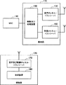
図1は、典型的セルラ移動体無線通信システムを示す。この典型的システムは、基地局110に類似したいくつのもの基地局及び移動体(mobile)120に類似したいくつもの移動体装置(mobile unit)又は移動局(mobile station)を含む。音声通信及び(又は)データ通信は、これらの装置又はこれらの装置の等価装置を使用して遂行することができる。基地局は制御及び処理装置130を含み、この装置はMSC(移動体交換センタ)140に接続され、MSCは、立ち代わって、公衆加入電話網(図示されていない)に接続される。
基地局110はセルにサービスしかつ音声チャネル・トランシーバ150によってハンドルされる複数の音声チャネルを含み、トランシーバ150は制御及び処理装置130によって制御される。また、各基地局は制御チャネル・トランシーバ160を含み、このトランシーバは2つ以上の制御チャネルをハンドルする能力を有することがある。制御チャネル・トランシーバ160は、制御及び処理装置130によって制御される。制御チャネル・トランシーバ160は、基地局又はセルの制御チャネルを通してこの制御チャネルにロックした移動体に制御情報を放送する。音声チャネル・トランシーバはトラフィック・チャネル又は音声チャネルを放送し、これらのチャネルはディジタル・チャネル位置情報を含むことができる。
移動体120が空きモードに入ると、移動体120はこれにアドレス指定されたページング・バーストの存在について基地局110のような基地局の制御チャネルを周期的に走査する。ページング・バーストは、移動体120にどのセルにロック・オン(lock on)又はキャンプ・ツー(camp to)するべきかを報せる。移動体120は、その音声及び制御チャネル・トランシーバ170で制御チャネル上の絶対及び相対情報放送を受信する。次いで、処理装置180が受信された制御チャネル情報を評価し、この情報は候補セルの特性を含みかつ移動局がどのセルにロックするべきかを決定する。受信された制御チャネル情報は、この情報が関連しているセルに関する絶対情報を含むだけでなく、またその制御チャネルが関連しているセルの直ぐ隣の他のセルに関する相対情報を含む。これら隣接セルは、周期的に走査される一方、より適当な候補があるかどうか判定するために主制御チャネルを監視する。移動体実施及び基地局実施についての特定の詳細(specifics)に関する追加情報は、1992年10月27日に出願され、P・デント(P.Dent)及びB・エクランド(B.Ekelund)に発行された「マルチモード信号処理(Multi-Mode Signal Processing)」と題する米国特許出願第07/967、027号に見付けることができ、この特許出願の全体は言及することによってその内容が本明細書に組み入れられる。察知されるように、サテライト利用(satellite-based)無線通信システムでは基地局を1つ以上のサテライトで置き換えてよい。
無線通信システム容量を増大させるために、周波数分割多元接続(Frequency Division Multiple Access;FDMA)、時分割多元接続(Time Division Multiple Access;TDMA)、及び符号分割多元接続(Code Division Multiple Access;CDMA)のようなディジタル通信及び多元接続技術が使用されると云ってよい。これらの多元接続の各々の目的は、異なる発信源(source)からの信号の宛先で、相互干渉を伴わずに異なるチャネルを分離できるように、これらの信号を共通伝送媒体上へ組み合わせることである。FDMAシステムでは、利用者は、周波数領域で無線スペクトルを共用する。各利用者は、会話全体を通して使用される周波数帯域の一部を配分される。TDMAシステムでは、利用者は、時間領域で無線スペクトルを共用する。各無線チャネル又は搬送周波数は一連のタイム・スロットに分割され、タイム・スロット中個々の利用者はシステムに配分された全周波数帯域にアクセスする(広帯域TDMA)か又はその帯域の一部にのみアクセスする(狭帯域TDMA)。各タイム・スロットは、データ源からの情報の「バースト」、例えば、音声会話のディジタル的に符号化された部分を含む。タイム・スロットは、所定持続時間を有する逐次TDMAフレームにまとめられる。各TDMAフレーム内のタイム・スロットの数は、無線チャネルを同時に共用することができる異なる利用者の数に関係する。もしTDMAフレーム内の各スロットが異なる利用者に割り当てられるならば、TDMAフレームの持続時間は、同じ利用者に割り当てられた逐次タイム・スロット間の最少量の時間である。CDMAは、FDMAとTDMAを組み合わせる。CDMAシステムでは、各利用者は、周波数時間領域に独特にアクセスするために特有の疑似ランダム利用者符号を割り当てられる。CDMA技術の例は、スペクトル拡散及び周波数ホッピングを含む。
TDMAシステムでは、同じ利用者に割り当てられた逐次タイム・スロットは搬送波上で常に連続タイム・スロットであるとは限らず、これらは利用者のディジタル・トラフィック・チャネルを構成し、このチャネルはその利用者に割り当てられた論理チャネルと考えられる。例としてGSM標準規格を使用するTDMAチャネルの組織を図2に示す。TDMAチャネルは、トラフィック・チャネルTCH及び信号チャネルSCを含む。TCHチャネルは、音声信号及び(又は)データ信号を伝送する通常料金チャネル(full-rate channel)及び半額料金チャネル(half-rate channel)を含む。信号チャネルSCは、移動体装置とサテライト(又は基地局)との間に信号情報を転送する。信号チャネルSCは、3型式の制御チャネル、すなわち、放送制御チャネル(BCCH)、多数の加入者間に共用される共通制御チャネル(CCCH)、及び単一加入者に割り当てられる専用制御チャネル(DCCH)を含む。BCCHチャネルは、周波数補正チャネル(FCH)及び同期チャネル(SCH)を含み、これらの両方共ダウンリンク・チャネルである。共通制御チャネル(CCCH)は、ダウンリンク・ページング・チャネル(PCH)及びアクセス承認(access grant;AGCH)チャネルばかりでなく、アップリンク・ランダム・アクセス・チャネル(RACH)を含む。専用制御チャネルDCCHは、高速関連制御チャネル(FACCH)、低速関連制御チャネル(SACCH)、及び独立専用制御チャネル(SDCCH)を含む。低速関連制御チャネルは、トラフィック(音声又はデータ)チャネル又は独立専用制御チャネル(SDCCH)に割り当てられる。SACCHチャネルは、電力及びフレームの調節及び制御情報を移動体装置に供給する。
放送制御チャネルの周波数補正チャネルFCHは、移動体装置に基地局に精確に同調させる情報を搬送する。放送制御チャネルの同期チャネルSCHは、移動体装置にフレーム同期データを供給する。
ランダム・アクセス・チャネルRACHは、移動体によってシステムにアクセス・リクエストするために使用される。RACH論理チャネルは、単方向アップリンク・チャネル(移動体から基地局又はサテライトへ)であり、かつ分離移動体装置によって共用される(たとえ重使用の期間中であっても、セル当たり1RACHが典型的システム内で充分である)。移動体装置は、チャネルが話中か又は空いているかどうか判定するためにRACHチャネルの状態を連続的に監視する。もしRACHチャネルが空いているならば、アクセスを望む移動体装置は、その移動体識別番号を所望電話番号と一緒に、RACH上を基地局又はサテライトへ送信する。MSCは、基地局又はサテライトからこの情報を受信し、かつ空き音声チャネルを移動局に割り当て、基地局又はサテライトを通して移動体へチャネル識別を伝送し、それであるから移動局はそれ自体を新チャネルに同調させることができる。RACHアップリンク・チャネル上の全てのタイム・スロットが、コンテンション制又は予約制のどちらかで、移動体アクセス・リクエストに使用される。予約制アクセスは、1993年10月25日に出願された「移動無線システム内でランダム・アクセスを達成する方法(Method of Effecting Random Access in a Mobile Radio System)」と題する米国特許出願第08/140、467号に説明されており、この特許出願は言及することによってその内容が本明細書に組み入れられる。RACH動作の重要な特徴は、或るダウンリンク情報の受信が要求され、それによって移動局がそれらがアップリンク上を送信したことごとくのバーストに対する実時間フィードバックを受信することである。これは、レイヤ2(Layer 2)ARQ、すなわちRACH上の自動繰返しリクエストとして知られている。ダウンリンク情報は、アップリンクに特定の層2情報を、他のダウンリンクで、搬送するのに専用された他のダウンリンク・サブチャネルのものであると考えてよい22ビットを、好適には、含む。共用チャネル・フィードバックと呼ぶことができるこの情報の流れは、RACHのスループット容量を増強し、それであるから移動局はどれかのアクセス企図のどれかのバーストが成功裡に受信されたかどうか敏速に判定することができる。図2に示されたように、このダウンリンク情報は、チャネルAGCH上を伝送される。
TDMAシステム内の信号の伝送は、バッファ・アンド・バースト(buffer-and-burst)、つまり不連続伝送モードで起こる。すなわち、各移動体装置は、その移動体装置の割り当てられた周波数でTDMA内のその割り当てられたタイム・スロット中にのみ送信又は受信する。通常料金では、例えば、移動局はスロット1中送信し、スロット2中受信し、スロット3中空き、スロット4中送信し、スロット5中受信し、スロット6中空き、次いで後続TDMAフレーム中このサイクルを繰り返す。電池式であることがある移動局を、それが送信も受信もしないタイム・スロット中電力を節約するためにスイッチ・オフする(又は「休眠(sleep)させる」ことができる。
移動性及び携帯性を向上するために、無線通信加入者は、大形アンテナ又は指向性アンテナを有する移動体装置よりも比較的小形、全方向性(したがって、あまり強力でない)アンテナを有する移動体装置を好む傾向がある。この好みのゆえに、小形の、全方向性アンテナを有する典型的移動体装置と移動体交換センタ(MSC)又はサテライトとの間の通信信号の交換のために充分な信号強度を供給することがときには困難である。この問題は、サテライト利用移動体無線通信では特に深刻である。
サテライト利用移動体無線通信システムは、部分的に重なり合う1つ以上のサテライト・ビームを使用して地球上の特定地域に無線通信サービスを提供する。各サテライト・ビームは、約1000kmまでの半径を有する。サテライトの電力制限に因り、ことごとくのビームに同時に高リンク・マージンを提供することは実行可能でない。
移動体サテライト・リンクは電力を厳しく制限されているので、通信はライシーン(Ricean)フェージングを伴う見通しチャネルに典型的に限定されている。ライシーン・フェージングは、弱い建築物反射波と一緒の、見通し経路と大地反射波との組合わせから起こる。これらのチャネルは、移動電話装置アンテナが適性に展開され、かつその装置が障害物のない位置にあるときのような、理想条件又は理想に近い条件で音声通信を達成するために、約10dB以上の通信リンク・マージンを要求する。これら理想に近い条件では、移動体装置は、入呼を検出するためにページング・チャネルを成功裡に監視することができる。移動体装置のアンテナが展開されないか又は移動体装置が障害物のある位置に(例えば、建築物内に)あるときのような、非理想条件では、大地反射波及び建築物反射波を含む反射波が支配的になる。これらの非理想条件におけるチャネルは、厳しい減衰を伴う平坦レーリー(flat Rayleigh)フェージング(最も厳しい型式のフェージング)によって特徴付けられる。このようなチャネルでは、信頼性ある音声通信又はデータ通信を達成するために30dBほど又はこれ以上のリンク・マージンが要求され、かつこの場合の移動体装置は入呼を検出するためにページング・チャネルを監視することができない。これらの非理想条件では、短メッセージ(SMS)が望ましい。サテライトの電力制限のゆえに、SMSは、移動局利用者に入呼について報せるために非理想条件で使用されるとき特に有効である。その際、移動体利用者は、その呼を受信又は返送するために位置を変えてよい。用語「リンク・マージン」又は「信号マージン」は、理想条件の下で、すなわち、相加性白色ガウス雑音(additive white Gaussian noise;AWGN)以外の障害(impairment)を持たないチャネルで要求される電力のほかに更に、適当なサービスを提供するために要求された追加電力を指す。「障害」は、信号振幅のエージング、ドップラー偏移、位相変動、信号シャドーイング(signals shadowing)又は信号ブロッケージ(signal blockage)、実施損失(implementation loss)、及びアンテナ放射パターンの異常を含む。
音声を伝送するにせよ又はデータを伝送するにせよ、特に電力を制限されたサテライト応用では、信頼性無線通信性能を保証するために信号マージンを増大させることが、しばしば望ましい。信号のマージン・リンクを増大させる既知の方法は、周波数選択性を達成するために又は(たたみ込み符号化のような)前進誤り訂正符号化(forward error correction coding)を使用するためにチャネル帯域幅を拡張すること、信号電力を増大させること、及びビット繰返し(これは前進誤り訂正符号化の或る1つの形であると見なすことができる)を含む。これらの方法の各々は、著しい制限を有する。帯域幅拡張は、典型的に、信号拡散(signal spreading)及び低ビット速度誤り訂正符号化のような既知の方法によって達成され、かつフェージングに対して低感度である信号を生じる。帯域幅拡張は、スペクトル分配効率を低下させる。更に、SMS応用では、もし音声チャネルの拡張された帯域幅がメッセージ・チャネルの帯域幅から(大きく)異なっているならば、移動体装置内に2つの別個のかつ完全な無線が(各サービス毎に1つずつ)必要とされることになり、それゆえその設計を複雑にする。また、コヒーレント・レーキ(coherent Rake)受信機又は等化器も、典型的に、遅延拡散(delay spread)を減少させるために要求され、移動体装置の設計を更に複雑にする。帯域幅拡張は、音声メセージ全体又はデータ・メッセージ全体の繰返し伝送によってまた実施されることがある。しかしながら、注目の非理想条件下では、この方法は、各繰返しが典型的に雑音フロア(noise floor)の下にあり(すなわち、充分なマージンを持たず)、高誤り率を生じかつ繰返しのコヒーレント積分を妨げると云う理由から、有効でない。
信号電力を増大させることがまた、より高いマージンを提供するために使用されることがある。これは、サテライトの電力制限のために、典型的に実行可能なアプローチではない。システムの費用を高めるのに加えて、増大した伝送電力がまた、狭い再使用マージンを備えるTDMAシステムでは特に、同一チャネル干渉を制御するのをいっそう困難にする。したがって、サテライトから移動体装置への大きな電力増強は、比較的軽使用の期間中に限って行われると云ってよい。更に、移動体装置はサテライトよりも電力をもっと制限されているので、この技術は、典型的に、サテライトから移動体装置へ一方向にのみ実行可能である。実行可能である。
(欧州特許出願第0 086 541号及び第0 212 667号に説明されたように)ビット繰返しはまた、マージンを増大させるために使用される。ビット繰返しは、特に非理想条件において、メッセージ繰返しよりも低い誤り率しか生じない。ビット繰返しは伝送遅延を起こす原因となり、この遅延は明白な理由から音声信号にとって望ましくない。しかしながら、伝送遅延は、その遅延が適度な最小限度に保たれるならば、SMS特徴のようなデータ通信にとって許容可能であることがある。ビット繰返しは、個々のビット又は個々の変調記号、又はビットのパケット又は変調記号のパケットを、全ての繰返しが連続している又は逐次TDMAフレームの同じタイム・スロット又は複数のタイム・スロット内に含まれるように、複数回伝送することによって達成される。受信機は、各繰返しからのエネルギーを積分して、より高いマージンを有する信号を作成する。上に注意したように、ビット繰返しは、メッセージの長さ次第で、著しい遅延を引き起こすおそれがある。30dB信号マージンを達成するには、各ビットを1000回繰り返さなければならないことになる。典型的短メッセージは、GSMシステム、すなわち、ヨーロッパ・ディジタル標準規格では32から64文字、米国で現在使用されているDAMPS(ディジタル高度移動電話サービス(Digital Advanced Mobile Phone Service))システムでは245文字まで、及びDECT(ディジタル・ヨーロッパ・コードレス電話(Digital European Cordless Telephone))システムでは160文字までを有する。18.64msのTDMAフレームを有し、フレーム当たり16スロットかつ114データ・ビット/スロットを備えるGSMシステムを想定すると、伝搬時間を含まない、64文字メッセージを受信するための最小遅延は、次のようになる。
64ビット×8ビット/文字×1000繰返し/ビット×18.64ms/スロット×1/114スロット/データ・ビット=84秒
このような遅延は、たとえデータ伝送であっても、極めて望ましくない。したがって、著しい遅延を伴うことなくかつ電力の著しい増大を伴うことなく増大した信号マージンで信号の伝送を図ることが無線通信システムにとって望ましいであろう。
チャネル帯域幅の拡張を要することなく増大した信号マージンで以て信号の伝送を図ることが通信システムにとって更に望ましいであろう。
TDMAフレームの構造又は組織に変化を要することなく増大した信号マージンで以て信号の伝送を図ることがTDMA通信システムにとってまた望ましいであろう。
増大した信号マージンで以て移動体装置から発信する又はサテライト又は基地局から発信するデータ・メッセージの伝送を図ることが移動無線通信システムにとって更に望ましいであろう。
データ・メッセージの伝送のために通信リンクの信号マージンを選択的に増大させることが通信システムにとって更に望ましいであろう。
発明の要約
従来の通信システム及び方法の上に挙げた制限及び他の制限は本発明によって克服され、本発明は短英数字メッセージを伝送する高透過伝送(high-penetration transmission)方法を提供し、この方法ではビット繰返し又はメッセージ繰返しと比較的小さな電力増大との組合わせによって信号マージンを増大させる。模範的実施例によれば、ビット繰返し又はメッセージ繰返しと比較的小さな電力増大との組合わせは、信号マージンを増大させるために繰返しに前面的に依存するシステムの許容不可能な遅延特性を回避する。同様に、繰返しと比較的小さな電力増大との組合わせは、信号マージンを増大させるために増大電力に前面的に依存するシステムの同一チャネル干渉問題を回避する。
本発明の模範的実施例によれば、移動無線通信システムは、移動体装置へ又はこれから英数字メッセージを伝送するために短メッセージ・サービス特徴を備える。厳しい減衰を伴うチャネルを通しての信頼性伝送を保証するために、短メッセージは、1つ以上のデータ符号語を形成するために誤り検出符号化を用いて符号化される。各符号語は、メッセージ・フレームを有するメッセージ・チャネルを通して多数回伝送される。各メッセージ・フレームは、各TDMAフレームからの又はTDMAフレームの各組からのタイム・スロットで作られる。メッセージ・チャネルは、音声伝送用電力レベルよりも大きいかつ制御情報伝送用電力レベルよりも大きい電力レベルで伝送される。メッセージ・チャネルは、放送制御チャネル又は他の適当なチャネルから取られたスロットによって形成されてよい。多数の伝送は、受信機で積分されかつ誤りを検査される。
【図面の簡単な説明】
本発明の上掲の目的、特徴、及び利点は、添付図面と関連して次の好適実施例の詳細な説明を読むならばいっそう容易に理解される。これらの図面において、
図1は模範的移動体無線通信システムのブロック図である。
図2は典型的GSMデイジタル無線通信システム内のチャネルの組織を示す線図である。
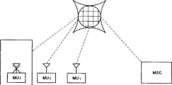
図3は本発明の信号伝送方法を実施することができるサテライト利用移動体無線通信システムの線図である。
図4は本発明の実施例による短メッセージの伝送を説明する流れ図である。
図5は本発明の実施例によるSMSスロットのバースト形式を示す線図である。
図6は本発明の実施例によるSMSサービスのフレーム形式を示す線図である。
好適実施例の詳細な説明
次の説明はサテライト利用無線通信システム内で実施される短メッセージ・サービスを目的とするが、察知されるように、本発明の原理はまた、他の型式の通信システムに応用することができる。
サテライト利用移動体無線通信システムでは、音声又はデータを伝送する通信リンクが、1つのサテライト、多数のサテライト、又は1つ以上のサテライトとPSTN(公衆交換電話網)との組合わせを通して移動局と標準電話機又は第2移動局のどちらかとの間のサテライト・ビーム上に確立されてよい。図3に示されたようなシステムは、地方エリアのような、少数の基地局しかない又は基地局がない、かつ追加基地局が実行困難である広い地理的カバレージを達成するために望ましいと云ってよい。サテライトの固有の電力制限に因り、サテライトと移動局との間の音声通信リンクは、理想条件又は理想に近い条件、すなわち、適性に展開された移動局のアンテナとの見通し通信のような条件を要求する。移動局がさえぎられている(例えば、建築物の内側にある等)とき又は移動局アンテナが適性に展開されていないときのような非理想条件では、チャネル内の大きくなった減衰のために、通信に対する電力マージン要件又は信号マージン要件がかなり増大する。(図3にMUzとして示された)このような状況では、レーリー・フェージングが満足な通信をしばしば妨げ、したがって、移動局に短英数字メッセージ送信することが望ましい。このメッセージは、例えば、加入者に入呼について通知するために使用されてよい。本発明は、著しい遅延、電力増大、又は同一チャネル干渉を伴うことなく信号マージンを増大させる効率的な技術を講じることによってメッセージの信頼性のある伝送を保証する。
説明のみの目的のためにかつ本発明の範囲を限定することなく、TDMAチャネルを使用するサテライト利用GSM無線通信システムを次の条件を示すと想定してよい。通信チャネルは見通し成分を有さず、かつ厳しい減衰を伴う平坦レリー・フェージングを受ける。技術の熟練者によって察知されるように、レーリー(又は多重路)フェージングは、サービス・エリア内の物理的構造からの反射に因って多重路波が定在波対を形成するときに起こる現象である。一緒に加算された定在波対は、不規則波フェージング構造を形成する。移動体装置が定在しているとき、この装置は定信号を受信する。しかしながら、移動体装置が運動するとき、このフェージング構造はフェージングを引き起こさせ、このフェージングは移動体装置が高速で運動するに連れて甚だしくなる。非理想レーリー・チャネルの平均信号レベルは、理想に近い見通しチャネルの信号レベルより約20〜30dB低い。
非理想条件で移動体装置への短メッセージの信頼性ある伝送を保証するためには、信号マージンを増大させなければならない。本発明によれば、ビット繰返し又はメッセージ繰返しと電力増大とを、著しい遅延を伴うことなく信号マージンを増大させるように組み合わせることができる。
知られているように、デシベル(dB)は電力比、電流比、又は電圧比を表すために使用される単位である。特に、電力比(P2/P1)は、式dB=10log(P2/P1)によってデシベルで表されることがある。10log1000=30であるから、30dBの信号マージンは1000と云う電力比である。それゆえ、この信号マージンをビット繰返しによって全面的に達成するためには、各ビットを1000回繰り返さなければならず、かつ各繰返しからの信号マージンを受信機で積分しなければならず、上掲から計算して82秒の遅延を生じる。しかしながら、15dBのマージンを達成するためには、10log31.623=15であるから、要求される電力比は31.623に過ぎない。それゆえ、30dBマージンは、15dBだけ電力を増大させかつ約31回各ビットを繰り返すことによって、提供することができる。この技術を使用すると、64文字メッセージに対するビット繰返し遅延は、(64文字×8ビット/文字×31繰返し/ビット×18.64ms/スロット×1/114スロット/ビット)約2.5秒である。結果として、ビット繰返し遅延が適度なレベルに維持され、かつ電力レベルもまた適度なレベルに維持され、それによって同一チャネル干渉を回避する。察知されるように、繰返しと電力増大との多くの異なる組合わせが、著しい遅延を伴わずにレーリー・フェージング環境内で逐次通信を達成するために可能である。更に、ディジタル信号の個々のビットを繰り返すよりはむしろ、ビットの群を繰り返した方が良いことがある。
本発明を実施するために、サテライトから移動局への電力増大を、多数の利用者にわたる電力負荷を平均することによって提供してよい。すなわち、理想に近い条件にある移動体装置によって使用される通信チャネルは、それらの電力を非理想条件にある移動体装置への電力供給を増大させるために減少させられるかもしれない。電力増大はまた時間平均することによって提供され、この場合連続TDMAフレーム内の個々のスロットは増大電力レベルで伝送される。察知されるように、サテライトから移動局への電力増大はまた、技術上知られた他の技術によって達成されることがある。
移動体装置の電力制限は、サテライトの電力制限よりもなお厳しい。それゆえ、移動体からサテライトへの通信に対して電力を増大させることはなおいっそう困難である。このような通信は、メッセージ又はメッセージに対する肯定応答を送信するために必要であることがある。本発明の1実施例によれば、移動体装置からサテライトへの電力増大は、移動体装置にランダム・アクセス・チャネルRACHの全てのタイム・スロット上で送信させることによって達成される。ビット繰返し又はメッセージ繰返しはまた、移動体装置がサテライトへ伝送する信号のマージンを更に有効に増大させることによって実施される。RACHチャネルを通しての移動体装置による肯定応答は低情報速度を有する信号によって完遂されてよいから、順方向チャネルに対してより多くの同期ビット、及びより多くのビット繰返し又はメッセージ繰返しを移動体装置の低伝送電力を補償するために使用することができる。好適には、移動体装置は、それらの繰返しを逆相関する(decorrelate)ために分離搬送周波数上で連続繰返しを伝送する。メッセージは短いので、伝送時間は短いことになり、かつ平均伝送電力はこのシステムを使用して許容可能になる。
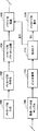
図4は、本発明の伝送方法を使用する短メッセージの伝送を説明する流れ図を示す。ステップ100で、送信当事者(sending party)が受信加入者に伝送しようとするメッセージを入力する。メッセージは、送信当事者によって移動体装置、標準電話機、コンピュータ端末、又は等価な装置を通して直接通信システムに入力されるか、又はシステムにメッセージを入力するサービス・センタのオペレータを呼び出すことによって直接入力されてよい。ステップ102で、短メッセージを含む情報ビットが送信機内に設置された符号化器によって、CRCのような誤り検出符号を用いて符号化される。符号化メッセージは1つ以上の符号語を構成し、符号語の各々が符号語ビット又は符号語記号を含む。もとより承知のように、受信機はサテライト、基地局、又は移動体装置であってよい。ステップ104で、符号化手段によって出力された符号語ビット又は符号語記号の各々をN回繰り返してNビットを含むパケットを形成するように、ビット繰返しを採用することができる。個々のビット又は記号を繰り返す代わりに、2つ以上のビット又は記号の群、又は符号語全体又はいくつかの符号語を繰り返すこともできることは、明らかである。次いで、受信機にチャネル品質を推定可能とするために、TDMAフレーム内の各スロットが繰返しビット、誤り検出符号化ビット、及び同期バーストの1つ以上のパケットを含むように、パケットが伝送される。符号化短メッセージを含む全てのビットが、このようにして伝送される。もしビット繰返し及びメッセージ繰返しが採用されるならば、いったん符号化メッセージ全体が伝送された上で、所望信号マージンを達成するために(N符号語ビットのパケットの形での)メッセージの伝送をM回繰り返すことができる。察知されるように、短メッセージをサテライト、基地局、又は移動局から送信してよいから、符号化機能及び伝送機能はこれらの装置の各々内に備えられる。また察知されるように、本発明の技術を実施するために、ビット繰返しの数N、メッセージ繰返しの数M、及びメッセージの成功裡伝送に要求された信号マージンを達成するために必要な電力増大を決定する手段が送信機内に含まれる。
ステップ108で、受信装置(すなわち、移動体装置、サテライト、基地局、又は等価装置)が、繰返し符号化メッセージ・ビット、誤り検出ビット、及びチャネル品質推定ビットを含む受信した信号をサンプルし、かつ次の形の計量和(metric sum)を発生する。
![]()
![]()
ステップ112で、受信装置に含まれた誤り検出器が送信装置で施されたCRC誤り検出符号化に基づいて誤りを検出する。もし誤りが検出されないならば、ステップ114でメッセージが受信加入者の移動体装置上に表示される。もし誤りが検出されるならば、そのメッセージは受信装置に表示されないで、利用者は表示された誤りメッセージによって又は音声信号によって誤りのあるメッセージについて注意され、かつ受信機は送信機に、下に更に詳細に説明される双方向無線プロトコルに従ってメッセージ又はそのメッセージの誤りのある部分を再伝送することをリクエストする。
本発明によれば、メッセージの繰返し伝送をメッセージの個々の部分の繰返しと組み合わせて使用してよい。すなわち、メッセージの個々の部分を多数回伝送してよく、かつそのメッセージ全体がメッセージ部分の繰返し伝送によって伝送されたとき、そのメッセージ全体を再び伝送してよい。
本発明の代表的実施例によれば、高透過短メッセージ・サービスを上に説明した伝送方法を使用して次のようにサテライト利用電気通信システム内に実施することができる。放送制御チャネルBCCHを含む搬送周波数上で、各(例えば、16スロット)フレームの第1ッスロットがその放送制御チャネルに分配される。放送制御チャネルは、51フレームにわたって実施される。パターンを繰り返す51フレームは、周波数補正チャネルFCH及び同期制御訂正チャネルSCHばかりでなく、放送及びページング・チャネルPCHを含む。サテライト・モードBCCHを伝送する搬送波は、全てのタイム・スロット内で必ずしも活性でない。特に、もし会話が所与のビームの搬送波上で現在なされていないならば、搬送波のBCCHスロットだけがエネルギーを含んでよい、すなわち、搬送波上のトラフィック・スロット及び他のスロットはエネルギーを含まないことになる。
各BCCHスロットは、好適には、搬送波のトラフィック・スロットの平均電力レベルより高い電力レベルで伝送される。好適には、BCCHの周波数補正チャネルFCH及び同期チャネルSCHは、短メッセージ・サービスに使用される。この実施例では、51スロットBCCHフレーム内の4スロットが短メッセージ・サービスに専用される。これらのSMSスロットは、フレーム1、13、26、及び40内に起こる。それゆえ、51スロットBCCHフレームにわたって、SMSスロットは12、13、14、12、12、13、14、…スロット分だけ間隔を取っており、受信機に信号強度プロファイルによってフレーム・タイミングを全面的に決定する余地を与える。4SMSスロットが残りの47BCCHスロットより高い電力レベルで伝送され、これら残りのBCCHスロットはBCCHチャネルを含む搬送波上の残りのTDMAチャネル・スロットより高い電力レベルで伝送される。察知されるように、放送制御チャネルBCCHのこの実施は、周波数補正チャネルFCHが無変調バーストでないと云うことにおいて標準GSM実施と異なる。
図5は、本発明の代表的実施例によるSMSスロット上を伝送されるバーストの書式を示す。このバーストはビーム識別ビットBEAM IDを含み、この識別ビットはサテライト及び使用されているそのビームを識別する。もし14ビットがBEAM IDに使用されるならば、16,384の特有識別子が可能である。これは、例えば、32サテライトの各々について512ビームまでの識別を識別させる。察知されるように、これらの識別子を個々の周波数上で再使用してよい。受信機は、BEAM ID情報の信号マージンを有効に増大させるために多数のSMSバーストの各々内の対応するビットを連続的に平均することができ、非理想環境においてさえもBEAM IDを判断できるようにする。
SMSバーストは、128ビット・データ符号を形成する更に2つの64ビット・データ符号DATACODEを含む。128ビット・データ符号は、1と128との間の或る1つの数の相互直交値(mutually orthogonal value)を有することできる。これらの直交値は、ビット・パターンに似た同期語であり、したがって省かれたチャネルFCH及びSCHを有効に置き換えるために周波数補正機能及び同期機能を提供する。代表的実施例によれば、もし128の相互直交値を想定するならば、各バースト内に情報の7ビットが供給される。この実施例では、各メッセージは、2回繰り返される。代わりに低い数の相互直交値を想定してもよく、かつ同じ総合データ・スループットを維持しながら、メッセージ伝送の数を減らすことができる。下に更に詳細に説明するように、誤り訂正符号化もまた使用してよい。
典型的SMSメッセージは、例えば、112ビットを含む。これらの112ビットは、情報ビット及びCRC誤り検出符号ビットを含む。112ビットを2回伝送するためには、224メッセージ・ビットを伝送しなければならない。図5に示したように、各SMSバーストは156.25ビットを含み、これらのビットは保護機能及びランプ・アップ−ダウン(ramp up/dwon)機能用8.25ビットGUARD/RAMP、6テール・ビットTAIL、及び142情報ビットを含む。142情報ビットは、14BEAM IDビット及び128データ符号ビットを含む。128データ符号ビットは7情報ビットに相当するので、7メッセージ・ビットが各SMSバースト内に伝送される。224メッセージ・ビットを送達するために、32SMSバーストが要求される。各51スロットBCCHフレーム毎に4SMSバーストがあるから、各メッセージ毎に408BCCHフレームが要求される。9.23msのフレーム長に基づいて、112ビット・メッセージが約3.77秒に送達される。察知されるように、もしサテライト・システムが121ビームを含むならば、サテライトは毎秒(121/3.77)約32メッセージを送達することができる。
上の代表的実施例によるSMSシステムを実施するために要求される電力は、次のように決定することができる。上に実施されたBCCHチャネルは、毎TDMAフレームに1BCCHバーストを生じ、それゆえ、BCCHバーストは、第16スロット毎に1回起こる。所与のBCCHバーストが起こることがある特定スロットは、好適には、16セル・パターン内でサテライト・ビームからサテライト・ビームへスタガ配置を取る。サテライトが121ビームを持つと想定すると、SMS情報を伝送する能力を有する約8ビームが所与の時刻に活性である間に、他の113ビームはトラフィック情報を伝送しつつある。先に説明したように、SMSスロットは、間隔を取ってBCCHフレームのスロット1、13、26、及び40内にある。この間隔は、異なるビーム内に12直交スタガ配置SMSフレームを考慮している。それゆえ、8ビームであってSMS情報を搬送する能力を有する同時に伝送するビームは、SMS情報を同じ時刻には伝送しない。SMSスロットは1回に1ビームのみ内で伝送され、それによって一定総合フェーズド・アレー送信機ローディング(constant total phased array transmitter loading)を維持する。
SMS信号に対するリンク・マージンは、増大電力と、128ビット・データ符号からの信号拡散と、ビット繰返し又はメッセージ繰返しと、誤り訂正符号化に因る利得との組合わせによって有効に増大される。上に説明した例に対するリンク・マージンを、符号化利得を除いて、次のように決定することができる。トラフィック・チャネルは、AWGNチャネルを通して最小7dBマージンを提供する。SMSチャネルはトラフィック・チャネルを通して9dB追加電力を使用して伝送され、AWGNチャネルを通して16dBの増大マージンをもたらす。7情報ビット用128チップ符号に因る拡散利得は追加12.6dB利得を提供し、28.6dBの増大マージンをもたらす。最後に、ソフト判断復号に関連して使用されたメッセージ繰返しが追加3dB利得を提供し、約31.6dBの合計SMSリンク・マージンをもたらす。誤り訂正符号化は追加利得を提供するから、察知されるように、本発明によるSMSシステムは、移動体装置がさえぎられる及び(又は)そのアンテナが適正に展開されないときのような非理想条件においてさえも、通信を図るために充分なリンク・マージンを提供する。
上に説明したように、本発明によるSMSシステムは、たとえSCHチャネルがSMS伝送に使用されても、同期を達成させる。本発明によれば、同期を次のように達成することができる。受信機が平均受信信号強度に基づいて電力プロファイル方法を使用してより高い電力SMSバーストを位置検出する。受信機は、各SMSバースト内の直交データ符号との相関によって、それ自体、ビット・レベルについて入信号と同期する。これらの相関は、メッセージ繰返しにわたって追加されて、メッセージ・データを信頼性を以て復号するために適当な信号対雑音比を提供する。いったん同期を達成すると、移動体装置は、47BCCHスロット中休眠しかつ4SMSスロット中目覚め、約1/204のデューティサイクルを生じる。移動体装置はまた、例えば、それが正常発信チャネルを受信することができるかどうか判定するために、各51フレーム期間にわたって追加4〜8スロット目覚めることがある。この追加の受信機活動は、約1.5のデューティサイクルを生じる。
察知されるように、本発明によるSMSシステムは他の仕方で実施されてもよく、上に説明した代表的実施例の特定詳細に限定されない。それゆえ、本発明のSMSシステムをTDMAシステム内のどれか特定のスロット又はNフレーム毎のスロットを使用して実施してよい。例えば、各サテライト・ビーム内の所与の搬送周波数上の第4フレーム毎のページング・スロットをSMSサービスを選択的に提供するために使用することができる。SMSサービスが必要でない又は所望されないとき、これらのスロットを音声トラフィックに使用することができる。この実施例では、同じ搬送波上の音声トラフィックより6dB多い電力を使用して伝送する。図6に示すように逐次SMSスロットは、13スロットSMSフレームを形成する。この実施例のSMSフレームは、周波数補正情報に使用される第1スロット及び同期情報に使用される第2スロットを有する。スロット3〜13は、データ又はページングに使用されかつ図5に示した書式のものである。各スロットは、1受信機のみに対する情報ビットを搬送する。この実施例の各ビット及び各メッセージは、3回伝送することができる。120データ・ビットで構成される典型的メッセージについては、1メッセージを送達する時間は、約11.5秒である。150ビームを有するサテライトを想定すると、13メセージを毎秒送達することができる。
本発明の更に他の態様によれば、メッセージ繰返しは、例えば、異なる周波数上で、異なる偏波上で、又は適当な時間遅延で、メッセージ又はメッセージの部分を伝送することによって、逆相関される。
本発明の伝送システムは、更に前進誤り訂正(FEC)手段を含んでよい。このような構成では、送信機は、誤り検出符号を伴う情報ビットを符号化した後、誤り訂正符号を備えた短メッセージの情報ビットを符号化する第2符号化器を備える。先に説明したようにして、メッセージが伝送されかつ受信したメッセージが復号される。論理多数決を用いる場合、ハード判断復号器を採用し、かつ論理多数決器(majority logic voter)の出力におけるビットを、(チャネルから推定したビット信頼性情報のような)追加情報を伴わずにチャネル復号器に供給する。もしソフト組合わせを使用するならば、誤り訂正符号を復号するためにソフト判断復号器を採用し、かつ計量和yjをソフト判断復号器の出力に加算し、かつその和を誤り訂正復号器に供給する。もし誤り訂正復号器の異なる出力が連続出力ビットを伝送流内で可能な限り分離することによってインタリーブされるならば、誤り訂正符号化がより有効になる。
察知されるように、ビット繰返し及びメッセージ繰返しの数が大きくなるほど、システムの性能は良くなるが、しかし遅延はますます長くなる。TDMAスロットは、同期情報又はデータのどちらかとして使用されることがある有限数のビットを有する。パケット内のビット繰返しの数(N)を増大させることは、必然的に同期ビットの数の減少を要求する。計量和は推定チャネル品質に依存し、及びチャネル品質は同期ビットの数に依存する。もしTDMAスロットがNtビットを有するならば、Ns同期ビット/スロット、かつNt−Nsデータビット毎スロットがあり、したがって、繰返しに因るビット当たり信号対雑音比の利得は約(NtNs−Ns2)/Ntである。したがって、信号対雑音比の最適利得は、Ns=Nt/2のとき起こる。しかしながら、察知されるように、同期ビット及びデータ・ビットの数の選択は、実施しようとする特定伝送方式次第である。
上に説明したように、サテライトと移動局との間にメッセージを通信するために確立されたリンクは双方向リンクである。したがって、無線プロトロルが、短メッセージ・システムのユーティリティを増強するために、サテライトと移動局との間での使用に選択されてよい。例えば、メッセージを受信する移動局がメッセージを正しく受信したかどうかを表示するために「YES」又は「NO」でサテライトに応答する簡単なプロトコルを実施することがある。代わりに、パケット又はパケットの群が群IDによって識別されかつCRC誤り訂正符号によって保護される複雑なプロトコルを実施することができる。もしCRCがメッセージは正しく受信されなかったと表示するならば、サテライトは誤りのある群を含むパケットを再送することができる。完全メッセージを再送するのに反して、この仕方では、誤りを伴うパケットのみを再伝送すればよい。それゆえ、このプロトコルを、繰返し数を最適化し、それによって遅延及び浪費サテライト電力を最少限にするために、使用することができる。
本発明によるSMSの双方向リンクはまた、課金(billing)に関して利点を備える。単方向リンクは、メッセージが正しく受信された証拠がないので、短メッセージ送達料を送信者又は受信者(recipient)に課するのを妨げる。それゆえ、短方向リンクを備えるSMSサービスは、高い加入者料金で加入者に提供されることがある。対照的に、双方向リンクはメッセージの送信者又はサービス・オペレータにメッセージが正しく受信されたかどうかを判定させるので、サービス・オペレータは各正しく受信されたメッセージのみに対する送達料で以てSMSサービスを提供することができる。
上に論じたように、より長いメッセージ、音声通信、又は30〜40dBより大きいリンク・マージンを要求する条件は、本発明の技術において許容不可能な長い遅延を生じることがある。こような場合、メッセージをサテライト又は相当するセルラ移動体交換センタ(MSC)で記憶してよい。移動体装置がより都合の良い通信チャネルの放送制御チャネル(BCCH)を読み出すことができるとき、その装置は、記憶されたメッセージについて、例えば、放送制御チャネル上のフラグによって報される。
上掲の説明は多くの特殊性を含むが、開示された代表的実施例は解説目的のみのためであって、本発明を制限するのではない。添付の請求の範囲及びこれらの適法等価事項によって明確にされたように、本発明の精神に反することがない多くの変形実施例は、技術の熟練者に容易に明らかである。Background of the Invention
The present invention generally relates to mobile communications. In particular, the present invention relates to satellite mobile communication methods and systems that allow mobile devices to selectively exchange signals with multiple satellites.
FIG. 1 shows a typical cellular mobile radiocommunication system. This exemplary system includes a number of base stations similar to
When mobile 120 enters idle mode, mobile 120 periodically scans the control channel of a base station, such as
In order to increase the capacity of a radio communication system, frequency division multiple access (FDMA), time division multiple access (TDMA), and code division multiple access (CDMA) It can be said that such digital communication and multiple access technologies are used. The purpose of each of these multiple access is to combine these signals onto a common transmission medium so that the destinations of the signals from different sources can separate different channels without mutual interference. . In an FDMA system, users share a radio spectrum in the frequency domain. Each user is allocated a portion of the frequency band used throughout the conversation. In a TDMA system, users share the radio spectrum in the time domain. Each radio channel or carrier frequency is divided into a series of time slots, during which time individual users access the entire frequency band allocated to the system (wideband TDMA) or only a part of that band. (Narrowband TDMA). Each time slot contains a “burst” of information from the data source, eg, a digitally encoded portion of a voice conversation. Time slots are grouped into sequential TDMA frames having a predetermined duration. The number of time slots in each TDMA frame is related to the number of different users that can share the radio channel simultaneously. If each slot in a TDMA frame is assigned to a different user, the duration of the TDMA frame is the minimum amount of time between successive time slots assigned to the same user. CDMA combines FDMA and TDMA. In a CDMA system, each user is assigned a unique pseudo-random user code to uniquely access the frequency time domain. Examples of CDMA techniques include spread spectrum and frequency hopping.
In a TDMA system, sequential time slots assigned to the same user are not always continuous time slots on the carrier, which constitute the user's digital traffic channel, which is the Logical channel assigned to the user. The organization of a TDMA channel using the GSM standard as an example is shown in FIG. The TDMA channel includes a traffic channel TCH and a signaling channel SC. The TCH channel includes a full-rate channel and a half-rate channel for transmitting voice signals and / or data signals. The signal channel SC transfers signal information between the mobile device and the satellite (or base station). The signaling channel SC is a type of control channel, namely a broadcast control channel (BCCH), a common control channel (CCCH) shared among a number of subscribers, and a dedicated control channel (DCCH) assigned to a single subscriber. including. The BCCH channel includes a frequency correction channel (FCH) and a synchronization channel (SCH), both of which are downlink channels. The common control channel (CCCH) includes an uplink random access channel (RACH) as well as a downlink paging channel (PCH) and an access grant (AGCH) channel. The dedicated control channel DCCH includes a high speed related control channel (FACCH), a low speed related control channel (SACCH), and an independent dedicated control channel (SDCCH). The low speed associated control channel is assigned to a traffic (voice or data) channel or an independent dedicated control channel (SDCCH). The SACCH channel provides power and frame adjustment and control information to the mobile device.
The frequency correction channel FCH of the broadcast control channel carries information that causes the mobile device to accurately tune to the base station. The broadcast control channel synchronization channel SCH supplies frame synchronization data to the mobile device.
The random access channel RACH is used by the mobile to request access to the system. The RACH logical channel is a unidirectional uplink channel (from mobile to base station or satellite) and is shared by separate mobile devices (1 RACH per cell is typical, even during periods of heavy use). Is sufficient in a dynamic system). The mobile device continuously monitors the status of the RACH channel to determine if the channel is busy or free. If the RACH channel is free, the mobile device desiring access transmits its mobile identification number along with the desired telephone number to the base station or satellite on the RACH. The MSC receives this information from the base station or satellite and assigns a free voice channel to the mobile station and transmits the channel identification to the mobile through the base station or satellite so that the mobile station makes itself a new channel. Can be tuned. All time slots on the RACH uplink channel are used for mobile access requests, either on a contention basis or on a reservation basis. Reservation-based access is described in US patent application Ser. No. 08/140, filed Oct. 25, 1993, entitled “Method of Effecting Random Access in a Mobile Radio System”. 467, the contents of which are incorporated herein by reference. An important feature of RACH operation is that some downlink information is required to be received, whereby the mobile station receives real-time feedback for bursts as they have transmitted on the uplink. This is known as
Transmission of signals within a TDMA system occurs in buffer-and-burst, i.e. discontinuous transmission mode. That is, each mobile device transmits or receives only during its assigned time slot in TDMA at the mobile device's assigned frequency. At normal rates, for example, the mobile station transmits in
In order to improve mobility and portability, wireless communication subscribers have mobiles with antennas that are relatively small, omnidirectional (and therefore less powerful) than mobile devices with large or directional antennas. There is a tendency to like the device. Because of this preference, it is sometimes necessary to provide sufficient signal strength for the exchange of communication signals between a typical mobile device with a small, omnidirectional antenna and a mobile switching center (MSC) or satellite. Have difficulty. This problem is particularly serious in satellite-based mobile radio communications.
A satellite-based mobile radio communication system provides radio communication services to specific regions on the earth using one or more satellite beams that partially overlap. Each satellite beam has a radius of up to about 1000 km. Due to satellite power limitations, it is not feasible to provide a high link margin for every beam simultaneously.
Because mobile satellite links are severely limited in power, communications are typically limited to line-of-sight channels with Ricean fading. Lycene fading results from the combination of line-of-sight and ground reflections along with weak building reflections. These channels are about 10 dB or more to achieve voice communications in ideal or near ideal conditions, such as when the mobile telephone equipment antenna is properly deployed and the equipment is in an unobstructed location. Request a communication link margin. Under these near ideal conditions, the mobile device can successfully monitor the paging channel to detect incoming calls. In non-ideal conditions, such as when the mobile device antenna is not deployed or the mobile device is in an obstructed location (eg, in a building), reflections that include ground and building reflected waves The waves become dominant. Channels in these non-ideal conditions are characterized by flat Rayleigh fading (the most severe type of fading) with severe attenuation. In such a channel, a link margin of as much as 30 dB or more is required to achieve reliable voice or data communication, and in this case the mobile device is a paging channel to detect incoming calls. Can not be monitored. In these non-ideal conditions, short message (SMS) is desirable. Because of satellite power limitations, SMS is particularly useful when used in non-ideal conditions to inform mobile station users about incoming calls. In doing so, the mobile user may change location to receive or return the call. The term “link margin” or “signal margin” refers to the power required under ideal conditions, that is, in a channel that has no impairment other than additive white Gaussian noise (AWGN). In addition, it refers to the additional power required to provide appropriate service. “Faults” include signal amplitude aging, Doppler shift, phase fluctuations, signal shadowing or signal blockage, implementation loss, and anomalies in the antenna radiation pattern.
Whether transmitting voice or transmitting data, particularly in power limited satellite applications, it is often desirable to increase the signal margin to ensure reliable wireless communication performance. Known methods for increasing the signal margin link are channel bandwidths to achieve frequency selectivity or to use forward error correction coding (such as convolutional coding). , Extending signal power, and bit repetition (which can be considered as one form of forward error correction coding). Each of these methods has significant limitations. Bandwidth expansion is typically achieved by known methods such as signal spreading and low bit rate error correction coding, and results in signals that are less sensitive to fading. Bandwidth expansion reduces spectral distribution efficiency. Furthermore, in SMS applications, if the expanded bandwidth of the voice channel is (largely) different from the bandwidth of the message channel, two separate and complete radios (for each service) are in the mobile device. One at a time), thus complicating its design. A coherent rake receiver or equalizer is also typically required to reduce delay spread, further complicating mobile device design. Bandwidth extension may also be implemented by repeated transmission of entire voice messages or data messages. However, under noticeable non-ideal conditions, this method can be used with each iteration typically under the noise floor (ie, not having sufficient margin), resulting in high error rates and coherent iterations. It is not effective because it hinders integration.
Increasing signal power may also be used to provide a higher margin. This is not typically a viable approach due to satellite power limitations. In addition to increasing system cost, the increased transmit power also makes it more difficult to control co-channel interference, especially in TDMA systems with a narrow reuse margin. Therefore, it can be said that the large power increase from the satellite to the mobile device is performed only during a relatively light use period. Furthermore, since mobile devices are more power limited than satellites, this technique is typically feasible in only one direction from the satellite to the mobile device. It is feasible.
Bit repetition (as described in European patent applications 0 086 541 and 0 212 667) is also used to increase the margin. Bit repetition results in a lower error rate than message repetition, especially in non-ideal conditions. Bit repetition causes transmission delay, which is undesirable for audio signals for obvious reasons. However, transmission delays may be acceptable for data communications such as SMS features if the delay is kept to a reasonable minimum. Bit repetition includes individual bits or individual modulation symbols, or packets of bits or packets of modulation symbols, in which all repetitions are consecutive or within the same time slot or multiple time slots of a sequential TDMA frame This is accomplished by transmitting multiple times. The receiver integrates the energy from each iteration to create a signal with a higher margin. As noted above, bit repetition can cause significant delays depending on the length of the message. To achieve a 30 dB signal margin, each bit must be repeated 1000 times. Typical short messages are GSM systems, ie 32 to 64 characters in the European digital standard, up to 245 characters in the DAMPS (Digital Advanced Mobile Phone Service) system currently used in the United States, And DECT (Digital European Cordless Telephone) systems have up to 160 characters. Assuming a GSM system with a TDMA frame of 18.64 ms and 16 slots per frame and 114 data bits / slot, the minimum delay for receiving a 64 character message without propagation time is: become.
64 bits × 8 bits / character × 1000 repetitions / bit × 18.64 ms / slot × 1/114 slot / data bit = 84 seconds
Such a delay is highly undesirable even for data transmission. Accordingly, it would be desirable for a wireless communication system to transmit a signal with an increased signal margin without significant delay and without significant increase in power.
It would be further desirable for communication systems to attempt to transmit signals with increased signal margins without requiring channel bandwidth expansion.
It would also be desirable for TDMA communication systems to attempt to transmit signals with increased signal margins without requiring changes to the structure or organization of the TDMA frame.
It would be further desirable for a mobile radio communication system to attempt to transmit data messages originating from mobile devices or originating from satellites or base stations with increased signal margin.
It would be further desirable for a communication system to selectively increase the signal margin of the communication link for transmission of data messages.
Summary of invention
The limitations and other limitations listed above for conventional communication systems and methods are overcome by the present invention, which provides a high-penetration transmission method for transmitting short alphanumeric messages, where The signal margin is increased by a combination of bit repetition or message repetition and a relatively small power increase. According to an exemplary embodiment, the combination of bit repetition or message repetition and a relatively small power increase avoids the unacceptable delay characteristics of a system that relies on repetition to increase signal margin. . Similarly, the combination of repetition and relatively small power increase avoids co-channel interference problems in systems that rely on increased power to increase signal margin.
In accordance with an exemplary embodiment of the present invention, a mobile radio communication system includes short message service features for transmitting alphanumeric messages to and from mobile devices. In order to ensure reliable transmission through the channel with severe attenuation, the short message is encoded using error detection coding to form one or more data codewords. Each codeword is transmitted multiple times through a message channel with message frames. Each message frame is made up of time slots from each TDMA frame or from each set of TDMA frames. The message channel is transmitted at a power level that is greater than the power level for transmitting voice and greater than the power level for transmitting control information. The message channel may be formed by a slot taken from a broadcast control channel or other suitable channel. Many transmissions are integrated and checked for errors at the receiver.
[Brief description of the drawings]
The foregoing objects, features and advantages of the present invention will be more readily understood when the following detailed description of the preferred embodiment is read in conjunction with the accompanying drawings. In these drawings,
FIG. 1 is a block diagram of an exemplary mobile radio communication system.
FIG. 2 is a diagram illustrating the organization of channels in a typical GSM digital wireless communication system.
FIG. 3 is a diagram of a satellite-based mobile radio communication system that can implement the signal transmission method of the present invention.
FIG. 4 is a flowchart illustrating transmission of a short message according to an embodiment of the present invention.
FIG. 5 is a diagram illustrating a burst format of an SMS slot according to an embodiment of the present invention.
FIG. 6 is a diagram showing a frame format of the SMS service according to the embodiment of the present invention.
Detailed Description of the Preferred Embodiment
Although the following description is directed to short message services implemented within a satellite based wireless communication system, it will be appreciated that the principles of the present invention can also be applied to other types of communication systems.
In a satellite-based mobile radio communication system, a communication link for transmitting voice or data is connected to a mobile station and a standard through one satellite, multiple satellites, or a combination of one or more satellites and a PSTN (Public Switched Telephone Network). It may be established on a satellite beam between either the telephone or the second mobile station. A system such as that shown in FIG. 3 would be desirable to achieve wide geographic coverage, such as in a rural area, where there are only a few base stations or no base stations and additional base stations are difficult to implement. It's okay. Due to the inherent power limitations of the satellite, the voice communication link between the satellite and the mobile station is subject to ideal or near-ideal conditions, i.e. conditions such as line-of-sight communication with an appropriately deployed mobile station antenna. Request. In non-ideal conditions, such as when the mobile station is blocked (eg inside a building) or when the mobile station antenna is not properly deployed, due to increased attenuation in the channel, Power margin requirements or signal margin requirements for communications are significantly increased. In such situations (shown as MUz in FIG. 3), Rayleigh fading often hinders satisfactory communications, and therefore it is desirable to send short alphanumeric messages to the mobile station. This message may be used, for example, to notify the subscriber about the incoming call. The present invention guarantees reliable transmission of messages by taking efficient techniques to increase signal margins without significant delay, power increase, or co-channel interference.
For illustrative purposes only and without limiting the scope of the present invention, a satellite-based GSM wireless communication system using a TDMA channel may be assumed to exhibit the following conditions: The communication channel has no line-of-sight component and is subject to flat Rally fading with severe attenuation. As will be appreciated by those skilled in the art, Rayleigh (or multipath) fading is a phenomenon that occurs when multipath waves form a standing wave pair due to reflections from physical structures within the service area. It is. The standing wave pairs added together form an irregular wave fading structure. When the mobile device is stationary, the device receives a constant signal. However, when the mobile device moves, this fading structure causes fading, which becomes more severe as the mobile device moves at high speed. The average signal level of the non-ideal Rayleigh channel is about 20-30 dB lower than the near-ideal line-of-sight signal level.
In order to guarantee reliable transmission of short messages to mobile devices in non-ideal conditions, the signal margin must be increased. According to the present invention, bit repetition or message repetition and power increase can be combined to increase the signal margin without significant delay.
As is known, decibel (dB) is a unit used to represent power ratio, current ratio, or voltage ratio. In particular, the power ratio (P2 / P1) may be expressed in decibels by the equation dB = 10 log (P2 / P1). Since 10 log1000 = 30, the signal margin of 30 dB is a power ratio of 1000. Therefore, to achieve this signal margin entirely by bit repetition, each bit must be repeated 1000 times, and the signal margin from each repetition must be integrated at the receiver, as described above. Resulting in a delay of 82 seconds. However, to achieve a 15 dB margin, 10 log 31.623 = 15, so the required power ratio is only 31.623. Therefore, a 30 dB margin can be provided by increasing the power by 15 dB and repeating each bit about 31 times. Using this technique, the bit repetition delay for a 64 character message is approximately 64 seconds (64 characters × 8 bits / character × 31 repetitions / bit × 18.64 ms / slot × 1/114 slot / bit). As a result, the bit repetition delay is maintained at a reasonable level, and the power level is also maintained at a reasonable level, thereby avoiding co-channel interference. As can be appreciated, many different combinations of repetition and power increase are possible to achieve sequential communication in a Rayleigh fading environment without significant delay. Further, it may be better to repeat a group of bits rather than repeat individual bits of a digital signal.
To implement the present invention, an increase in power from the satellite to the mobile station may be provided by averaging the power load across multiple users. That is, the communication channels used by mobile devices in near ideal conditions may be reduced to increase their power supply to mobile devices in non-ideal conditions. The power increase is also provided by time averaging, where individual slots within successive TDMA frames are transmitted at an increased power level. As will be appreciated, the power increase from the satellite to the mobile station may also be achieved by other techniques known in the art.
Mobile device power limits are still more stringent than satellite power limits. Therefore, it is even more difficult to increase power for communication from mobile to satellite. Such communication may be necessary to send a message or acknowledgment for the message. According to one embodiment of the present invention, the power increase from the mobile device to the satellite is achieved by having the mobile device transmit on all time slots of the random access channel RACH. Bit repetition or message repetition is also implemented by effectively increasing the margin of the signal that the mobile device transmits to the satellite. Acknowledgment by the mobile device over the RACH channel may be accomplished by a signal having a low information rate, so more synchronization bits and more bit repetitions or message repetitions for the forward channel It can be used to compensate for low transmission power. Preferably, the mobile device transmits successive repetitions on a separate carrier frequency to decorrelate those repetitions. Since the message is short, the transmission time will be short and the average transmitted power will be acceptable using this system.
FIG. 4 shows a flow diagram illustrating the transmission of a short message using the transmission method of the present invention. In
In
![]()
![]()
In
According to the invention, repeated transmission of messages may be used in combination with repetition of individual parts of the message. That is, an individual part of a message may be transmitted many times, and when the entire message is transmitted by repeated transmission of the message part, the entire message may be transmitted again.
According to an exemplary embodiment of the present invention, a highly transparent short message service can be implemented in a satellite based telecommunications system using the transmission method described above as follows. On the carrier frequency including the broadcast control channel BCCH, the first slot of each (for example, 16 slots) frame is distributed to the broadcast control channel. The broadcast control channel is implemented over 51 frames. The 51 frames repeating the pattern include not only the frequency correction channel FCH and the synchronization control correction channel SCH, but also the broadcast and paging channel PCH. A carrier carrying satellite mode BCCH is not necessarily active in every time slot. In particular, if no conversation is currently taking place on the carrier of a given beam, only the BCCH slot of the carrier may contain energy, i.e. traffic slots and other slots on the carrier do not contain energy. become.
Each BCCH slot is preferably transmitted at a power level higher than the average power level of the carrier traffic slot. Preferably, the BCCH frequency correction channel FCH and synchronization channel SCH are used for short message service. In this embodiment, 4 slots in a 51 slot BCCH frame are dedicated to short message service. These SMS slots occur in
FIG. 5 shows a format of a burst transmitted over an SMS slot according to an exemplary embodiment of the present invention. This burst contains a beam identification bit BEAM ID, which identifies the satellite and its beam being used. If 14 bits are used for the BEAM ID, 16,384 unique identifiers are possible. This, for example, identifies up to 512 beams for each of the 32 satellites. As can be appreciated, these identifiers may be reused on individual frequencies. The receiver can continuously average the corresponding bits in each of the multiple SMS bursts to effectively increase the signal margin of the BEAM ID information, so that the BEAM ID can be determined even in a non-ideal environment. To.
The SMS burst includes two more 64-bit data codes DATACODE that form a 128-bit data code. A 128-bit data code can have a certain number of mutually orthogonal values between 1 and 128. These orthogonal values are synchronization words that resemble bit patterns and thus provide frequency correction and synchronization functions to effectively replace the omitted channels FCH and SCH. According to an exemplary embodiment, if 128 cross-orthogonal values are assumed, 7 bits of information are provided in each burst. In this example, each message is repeated twice. Alternatively, a low number of cross-orthogonal values may be assumed and the number of message transmissions can be reduced while maintaining the same overall data throughput. Error correction coding may also be used, as described in more detail below.
A typical SMS message includes, for example, 112 bits. These 112 bits include information bits and CRC error detection code bits. To transmit 112 bits twice, 224 message bits must be transmitted. As shown in FIG. 5, each SMS burst includes 156.25 bits, which are 8.25 bit GUARD / RAMP, 6 tails for protection and ramp up / dwon functions. Bit TAIL and 142 information bits are included. The 142 information bits include 14 BEAM ID bits and 128 data code bits. Since 128 data code bits correspond to 7 information bits, 7 message bits are transmitted in each SMS burst. A 32 SMS burst is required to deliver 224 message bits. Since there are 4 SMS bursts for each 51-slot BCCH frame, a 408 BCCH frame is required for each message. Based on a frame length of 9.23 ms, a 112-bit message is delivered in approximately 3.77 seconds. As can be seen, if the satellite system includes 121 beams, the satellite can deliver about 32 messages per second (121 / 3.77).
The power required to implement the SMS system according to the above exemplary embodiment can be determined as follows. The BCCH channel implemented above results in one BCCH burst in every TDMA frame, and therefore a BCCH burst occurs once every 16th slot. A particular slot in which a given BCCH burst may occur preferably takes a staggered arrangement from satellite beam to satellite beam within a 16 cell pattern. Assuming that the satellite has 121 beams, the other 113 beams are transmitting traffic information while approximately 8 beams capable of transmitting SMS information are active at a given time. As explained earlier, the SMS slots are spaced within
The link margin for the SMS signal is effectively increased by a combination of increased power, signal spreading from a 128-bit data code, bit repetition or message repetition, and gain due to error correction coding. The link margin for the example described above can be determined as follows, excluding the coding gain. The traffic channel provides a minimum 7 dB margin through the AWGN channel. The SMS channel is transmitted using 9 dB additional power through the traffic channel, resulting in an increased margin of 16 dB through the AWGN channel. The spreading gain due to the 7 chip bits for 7 information bits provides an additional 12.6 dB gain, resulting in an increased margin of 28.6 dB. Finally, the message repetition used in connection with soft decision decoding provides an additional 3 dB gain, resulting in a total SMS link margin of approximately 31.6 dB. Since error correction coding provides additional gain, as can be seen, the SMS system according to the present invention is in non-ideal conditions such as when a mobile device is blocked and / or its antenna is not deployed properly. Even provides sufficient link margin for communication.
As explained above, the SMS system according to the present invention achieves synchronization even if the SCH channel is used for SMS transmission. According to the present invention, synchronization can be achieved as follows. The receiver locates the higher power SMS burst using a power profile method based on the average received signal strength. The receiver itself synchronizes with the incoming signal for bit level by correlation with the orthogonal data code in each SMS burst. These correlations are added over the message repetition to provide an appropriate signal to noise ratio to reliably decode the message data. Once synchronization is achieved, the mobile device sleeps during 47 BCCH slots and wakes up during 4 SMS slots, resulting in a duty cycle of approximately 1/204. The mobile device may also wake up for an additional 4-8 slots over each 51 frame period, for example, to determine if it can receive a normal outgoing channel. This additional receiver activity results in a duty cycle of about 1.5.
As will be appreciated, the SMS system according to the present invention may be implemented in other ways and is not limited to the specific details of the exemplary embodiments described above. Therefore, the SMS system of the present invention may be implemented using any particular slot in the TDMA system or every N frames. For example, a paging slot every fourth frame on a given carrier frequency in each satellite beam can be used to selectively provide SMS service. These slots can be used for voice traffic when SMS service is not needed or desired. In this embodiment, transmission is performed using 6 dB more power than voice traffic on the same carrier. As shown in FIG. 6, sequential SMS slots form a 13-slot SMS frame. The SMS frame of this embodiment has a first slot used for frequency correction information and a second slot used for synchronization information. Slots 3-13 are used for data or paging and are of the format shown in FIG. Each slot carries information bits for only one receiver. Each bit and each message in this embodiment can be transmitted three times. For a typical message consisting of 120 data bits, the time to deliver one message is about 11.5 seconds. Assuming a satellite with 150 beams, 13 messages can be delivered every second.
According to yet another aspect of the invention, message repetition is inversely correlated, for example, by transmitting a message or part of a message on different frequencies, on different polarizations, or with an appropriate time delay. .
The transmission system of the present invention may further include forward error correction (FEC) means. In such a configuration, the transmitter includes a second encoder that encodes information bits of an error detection code and then encodes information bits of a short message including an error correction code. As described above, the message is transmitted and the received message is decoded. When using logic majority, a hard decision decoder is used and the bits in the output of the majority logic voter are channel decoded without additional information (such as bit reliability information estimated from the channel) Supply to the vessel. If a soft combination is used, a soft decision decoder is employed to decode the error correction code and the metric sum y j Is added to the output of the soft decision decoder and the sum is supplied to the error correction decoder. If different outputs of the error correction decoder are interleaved by separating consecutive output bits as much as possible in the transmission stream, error correction coding becomes more effective.
As can be seen, the larger the number of bit repetitions and message repetitions, the better the system performance, but the longer the delay. A TDMA slot has a finite number of bits that may be used as either synchronization information or data. Increasing the number of bit repetitions (N) in a packet necessarily requires a reduction in the number of synchronization bits. The metric sum depends on the estimated channel quality, and the channel quality depends on the number of synchronization bits. If TDMA slot is N t N if it has bits s Sync bits / slot and N t -N s There is a slot per data bit, so the signal-to-noise ratio gain per bit due to repetition is approximately (N t N s -N s 2) / N t It is. Therefore, the optimal gain of the signal to noise ratio is N s = N t Occurs at / 2. However, as will be appreciated, the choice of the number of synchronization bits and data bits depends on the particular transmission scheme to be implemented.
As explained above, the link established for communicating messages between the satellite and the mobile station is a bi-directional link. Accordingly, a wireless protocol may be selected for use between the satellite and the mobile station to enhance the utility of the short message system. For example, a mobile station that receives a message may implement a simple protocol that responds to the satellite with “YES” or “NO” to indicate whether the message has been received correctly. Instead, a complex protocol can be implemented in which a packet or group of packets is identified by a group ID and protected by a CRC error correction code. If the CRC indicates that the message was not received correctly, the satellite can retransmit the packet containing the erroneous group. Contrary to resending a complete message, in this way, only packets with errors need to be retransmitted. Therefore, this protocol can be used to optimize the number of iterations, thereby minimizing delay and wasted satellite power.
The SMS bi-directional link according to the invention also provides advantages with respect to billing. Unidirectional links prevent a short message delivery fee from being charged to the sender or recipient because there is no evidence that the message was received correctly. Therefore, SMS services with short direction links may be offered to subscribers at high subscriber rates. In contrast, the bi-directional link allows the message sender or service operator to determine whether the message was received correctly, so that the service operator provides SMS service with a delivery fee for each correctly received message only. can do.
As discussed above, longer messages, voice communications, or conditions that require a link margin greater than 30-40 dB may cause unacceptably long delays in the techniques of the present invention. In such cases, the message may be stored at a satellite or a corresponding cellular mobile switching center (MSC). When the mobile device can read the broadcast control channel (BCCH) of the more convenient communication channel, the device is informed of the stored message, for example by a flag on the broadcast control channel.
While the above description includes many specificities, the exemplary embodiments disclosed are for illustrative purposes only and are not intended to limit the invention. Many modifications which do not depart from the spirit of the present invention will be readily apparent to those skilled in the art, as defined by the appended claims and their legal equivalents.
Claims (18)
1つ以上のデータ符号語を形成するために誤り訂正符号化を用いて伝送しようとする前記ショートメッセージを符号化するステップと、
前記符号化されたメッセージを1つ以上のデータ符号語を各々に含むパケットに分割するステップと、
前記制御スロットを含む少なくとも1つの制御チャネルを有するメッセージ・チャネルを通して、前記第2の電力レベルで複数の回数に亘り各データ符号語を伝送するステップであって、前記メッセージ・チャネルが複数のメッセージ・フレームを有し、各メッセージ・フレームが前記TDMA通信チャネルの前記各フレーム組からの1つ以上のタイム・スロットを含む前記伝送するステップと
を含む方法。A TDMA communication channel having a plurality of frame sets, each frame set including one or more frames, each frame including a plurality of time slots, and each time slot transmitting a plurality of data bits. A specific subscription through the TDMA communication channel including: a voice slot for transmitting voice information at a first power level; and a control slot for transmitting control information at a second power level higher than the first power level. A method for transmitting a short message including data information for a user to a user,
Encoding the short message to be transmitted using error correction encoding to form one or more data codewords;
Splitting the encoded message into packets each containing one or more data codewords;
Transmitting each data codeword a plurality of times at the second power level over a message channel having at least one control channel including the control slot, the message channel comprising a plurality of message channels; And transmitting each message frame including one or more time slots from each frame set of the TDMA communication channel.
1つ以上のデータ符号語を形成するために誤り訂正符号化を用いて伝送しようとする前記ショートメッセージを符号化する符号化器と、
前記符号化されたメッセージを1つ以上のデータ符号語を各々に含むパケットに分割する分割器と、
前記制御スロットを含む少なくとも1つの制御チャネルを有するメッセージ・チャネルを通して、前記第2の電力レベルで複数の回数に亘り各データ符号語を伝送する送信機であって、前記メッセージ・チャネルが複数のメッセージ・フレームを有し、各メッセージ・フレームが前記TDMA通信チャネルの前記各フレーム組からの1つ以上のタイム・スロットを含む前記送信機と
を含むシステム。A TDMA communication channel having a plurality of frame sets, each frame set including one or more frames, each frame including a plurality of time slots, and each time slot transmitting a plurality of data bits. A specific subscription through the TDMA communication channel including: a voice slot for transmitting voice information at a first power level; and a control slot for transmitting control information at a second power level higher than the first power level. A system for transmitting a short message including data information for a user to a user,
An encoder that encodes the short message to be transmitted using error correction encoding to form one or more data codewords;
A divider for dividing the encoded message into packets each containing one or more data codewords;
A transmitter for transmitting each data codeword a plurality of times at the second power level through a message channel having at least one control channel including the control slot, the message channel comprising a plurality of messages A system comprising a frame, and wherein each message frame includes one or more time slots from each frame set of the TDMA communication channel.
Applications Claiming Priority (3)
| Application Number | Priority Date | Filing Date | Title |
|---|---|---|---|
| US08/579,015 US5822310A (en) | 1995-12-27 | 1995-12-27 | High power short message service using broadcast control channel |
| US08/579,015 | 1995-12-27 | ||
| PCT/US1996/020640 WO1997024827A1 (en) | 1995-12-27 | 1996-12-23 | High-penetration transmission method for a radiocommunication system |
Publications (2)
| Publication Number | Publication Date |
|---|---|
| JP2000502866A JP2000502866A (en) | 2000-03-07 |
| JP4571237B2 true JP4571237B2 (en) | 2010-10-27 |
Family
ID=24315238
Family Applications (1)
| Application Number | Title | Priority Date | Filing Date |
|---|---|---|---|
| JP52453097A Expired - Lifetime JP4571237B2 (en) | 1995-12-27 | 1996-12-23 | Highly transparent transmission method for wireless communication system |
Country Status (8)
| Country | Link |
|---|---|
| US (1) | US5822310A (en) |
| EP (1) | EP0870377A1 (en) |
| JP (1) | JP4571237B2 (en) |
| KR (1) | KR100564861B1 (en) |
| CN (1) | CN1166105C (en) |
| AU (1) | AU708089B2 (en) |
| CA (1) | CA2241596C (en) |
| WO (1) | WO1997024827A1 (en) |
Families Citing this family (69)
| Publication number | Priority date | Publication date | Assignee | Title |
|---|---|---|---|---|
| SE504721C2 (en) * | 1994-08-19 | 1997-04-14 | Telia Ab | Device for telecommunication systems for sending short messages within the DECT system |
| ZA965340B (en) | 1995-06-30 | 1997-01-27 | Interdigital Tech Corp | Code division multiple access (cdma) communication system |
| US6046990A (en) * | 1995-11-15 | 2000-04-04 | Ericsson, Inc. | High-penetration transmission method for a radiocommunication system |
| US6414945B1 (en) | 1995-12-27 | 2002-07-02 | Ericsson Inc. | High power short message service using TDMA frames and/or broadcast control channel |
| US6314081B1 (en) | 1996-01-18 | 2001-11-06 | Ericsson Inc. | High power short message service using dedicated carrier frequency |
| US6606309B1 (en) * | 1996-11-19 | 2003-08-12 | Ericsson Inc. | Time-multiplexed short message acknowledgement systems and methods |
| US5991633A (en) * | 1997-02-07 | 1999-11-23 | Telefonaktiebolaget Lm Ericsson | Method of dynamically controlling the length of a R-- DATA messages on a random access channel |
| DE19708748B4 (en) * | 1997-02-25 | 2004-03-25 | Atx Europe Gmbh | Process and system for the provision and transmission of individualized traffic information |
| US5987322A (en) * | 1997-04-03 | 1999-11-16 | Ericsson Inc. | System specified adaptive mobile station behavior within a mobile telecommunications system |
| US5983384A (en) * | 1997-04-21 | 1999-11-09 | General Electric Company | Turbo-coding with staged data transmission and processing |
| FI109509B (en) * | 1997-06-03 | 2002-08-15 | Nokia Corp | Billing of a short message addressed to a mobile station |
| US6215762B1 (en) * | 1997-07-22 | 2001-04-10 | Ericsson Inc. | Communication system and method with orthogonal block encoding |
| US6349209B1 (en) * | 1997-09-23 | 2002-02-19 | At&T Corporation | Method for simplified telephone dialing |
| EP0915576A1 (en) * | 1997-10-30 | 1999-05-12 | ICO Services Ltd. | Transmission of notification signals to user terminals in a telecommunications network |
| DE19752197A1 (en) * | 1997-11-25 | 1999-05-27 | Siemens Ag | Transmission system for the transmission of digital signals in a radio access network |
| US6131027A (en) * | 1997-12-29 | 2000-10-10 | Motorola, Inc. | System for controlling network bandwidth |
| US6298095B1 (en) * | 1998-04-03 | 2001-10-02 | Telefonaktiebolaget Lm Ericsson (Publ) | Communicating signaling information in a cellular system that has a tight frequency reuse pattern |
| US6421357B1 (en) * | 1998-06-24 | 2002-07-16 | Ericsson Inc. | High-penetration radiocommunication system using a compact character set |
| US6850991B1 (en) * | 1998-12-22 | 2005-02-01 | Citibank, N.A. | Systems and methods for distributing information to a diverse plurality of devices |
| US6771953B1 (en) | 1998-12-31 | 2004-08-03 | At&T Corp. | Wireless centrex call transfer |
| US6654615B1 (en) | 1998-12-31 | 2003-11-25 | Albert Chow | Wireless centrex services |
| US6606493B1 (en) | 1998-12-31 | 2003-08-12 | At&T Corp. | Wireless centrex conference call deleting a party |
| US6587683B1 (en) | 1998-12-31 | 2003-07-01 | At&T Corp. | Unconditional call forwarding in a wireless centrex services system |
| US6745025B1 (en) | 1998-12-31 | 2004-06-01 | At&T Corp. | Time-of-day call forwarding in a wireless centrex services system |
| US6738615B1 (en) | 1998-12-31 | 2004-05-18 | At&T Corp. | Wireless centrex caller ID |
| US6643507B1 (en) | 1998-12-31 | 2003-11-04 | At&T Corp. | Wireless centrex automatic callback |
| US6591115B1 (en) | 1998-12-31 | 2003-07-08 | At&T Corp. | Wireless centrex call hold |
| US6819945B1 (en) | 1998-12-31 | 2004-11-16 | At&T Corp. | Wireless centrex feature activation/deactivation |
| US6574470B1 (en) | 1998-12-31 | 2003-06-03 | At&T Corp. | Programmable ring-call forwarding in a wireless centrex services system |
| US6374102B1 (en) * | 1998-12-31 | 2002-04-16 | At+T Corp. | User proactive call handling |
| US6711401B1 (en) | 1998-12-31 | 2004-03-23 | At&T Corp. | Wireless centrex call return |
| US6631258B1 (en) | 1998-12-31 | 2003-10-07 | At&T Corp. | Busy call forwarding in a wireless centrex services system |
| US6654603B1 (en) | 1998-12-31 | 2003-11-25 | At&T Corp. | Call waiting in a wireless centrex system |
| US6618600B1 (en) | 1998-12-31 | 2003-09-09 | At&T Corp. | Distinctive ringing in a wireless centrex system |
| US6606505B1 (en) | 1998-12-31 | 2003-08-12 | At&T Corp. | Wireless centrex call screen |
| US6535730B1 (en) | 1998-12-31 | 2003-03-18 | At&T Corp. | Wireless centrex conference call adding a party |
| US6307833B1 (en) * | 1999-02-16 | 2001-10-23 | Loral Cyberstar, Inc. | Rain fade mitigation in a data transmission system |
| US20020068527A1 (en) * | 1999-03-09 | 2002-06-06 | Larry William Massingill | Systems and methods for communicating messages to disadvantaged mobile user terminals |
| US6295283B1 (en) * | 1999-05-11 | 2001-09-25 | Trw Inc. | Method for providing connectionless data services over a connection-oriented satellite network by associating IP subnets with downlink beam identifiers |
| US20040228297A1 (en) * | 2000-11-17 | 2004-11-18 | Ihab Elzind | Smart antenna's for cellular modem networks |
| US20040160917A1 (en) * | 1999-06-22 | 2004-08-19 | Eliznd Ihab H. | Multibeam antenna for a wireless network |
| US6449488B1 (en) | 1999-08-25 | 2002-09-10 | Lucent Technologies Inc. | Quality of service based CDMA broadcast scheduler |
| US6766160B1 (en) | 2000-04-11 | 2004-07-20 | Nokia Corporation | Apparatus, and associated method, for facilitating authentication of communication stations in a mobile communication system |
| US7412227B2 (en) * | 2000-09-22 | 2008-08-12 | Siemens Aktiengesellschaft | Accounting of data transmission costs in a mobile radio/telephone network |
| US8199696B2 (en) * | 2001-03-29 | 2012-06-12 | Qualcomm Incorporated | Method and apparatus for power control in a wireless communication system |
| US6907028B2 (en) * | 2002-02-14 | 2005-06-14 | Nokia Corporation | Clock-based time slicing |
| US7844214B2 (en) * | 2002-03-02 | 2010-11-30 | Nokia Corporation | System and method for broadband digital broadcasting |
| US7200387B1 (en) | 2004-09-01 | 2007-04-03 | Cellco Partnership | Application invocation on a mobile station using messaging service |
| RU2303330C1 (en) * | 2006-02-13 | 2007-07-20 | Самсунг Электроникс Ко., Лтд. | Method for receiving signal in communication system with several channels for transmitting and receiving |
| DE102006038826A1 (en) * | 2006-08-18 | 2008-05-15 | Nokia Siemens Networks Gmbh & Co.Kg | Direction-dependent transmission of organizational information in a cross-system channel |
| EP2095543A1 (en) * | 2006-12-01 | 2009-09-02 | Fox Interactive Media Labs | Methods, systems, and computer program products for providing uplink collision identification |
| KR100779105B1 (en) * | 2006-12-07 | 2007-11-27 | 한국전자통신연구원 | WAN system using multi-channel with different radio wave strength and its configuration method |
| CN101159510B (en) * | 2007-11-16 | 2011-09-28 | 海能达通信股份有限公司 | Method for improving dependability of information bit transmission |
| US8988574B2 (en) | 2012-12-27 | 2015-03-24 | Panasonic Intellectual Property Corporation Of America | Information communication method for obtaining information using bright line image |
| JP2014127725A (en) * | 2012-12-25 | 2014-07-07 | Seiko Epson Corp | Demodulation method, demodulation device and electronic apparatus |
| US8922666B2 (en) | 2012-12-27 | 2014-12-30 | Panasonic Intellectual Property Corporation Of America | Information communication method |
| CN104871452B (en) | 2012-12-27 | 2018-04-27 | 松下电器(美国)知识产权公司 | Visual optical communication method and visual optical communication apparatus |
| US10951310B2 (en) | 2012-12-27 | 2021-03-16 | Panasonic Intellectual Property Corporation Of America | Communication method, communication device, and transmitter |
| US9608727B2 (en) | 2012-12-27 | 2017-03-28 | Panasonic Intellectual Property Corporation Of America | Switched pixel visible light transmitting method, apparatus and program |
| US9087349B2 (en) | 2012-12-27 | 2015-07-21 | Panasonic Intellectual Property Corporation Of America | Information communication method |
| US10523876B2 (en) | 2012-12-27 | 2019-12-31 | Panasonic Intellectual Property Corporation Of America | Information communication method |
| CN104871454B (en) | 2012-12-27 | 2018-09-28 | 松下电器(美国)知识产权公司 | Information communicating method and information-communication device |
| US10530486B2 (en) | 2012-12-27 | 2020-01-07 | Panasonic Intellectual Property Corporation Of America | Transmitting method, transmitting apparatus, and program |
| US9608725B2 (en) | 2012-12-27 | 2017-03-28 | Panasonic Intellectual Property Corporation Of America | Information processing program, reception program, and information processing apparatus |
| EP2940893B1 (en) * | 2012-12-27 | 2021-05-19 | Panasonic Intellectual Property Corporation of America | Information communication method |
| US9088360B2 (en) | 2012-12-27 | 2015-07-21 | Panasonic Intellectual Property Corporation Of America | Information communication method |
| US10303945B2 (en) | 2012-12-27 | 2019-05-28 | Panasonic Intellectual Property Corporation Of America | Display method and display apparatus |
| PL3596780T3 (en) | 2017-03-13 | 2022-01-31 | Telefonaktiebolaget Lm Ericsson (Publ) | Self-calibration of antenna array system |
| WO2020064128A1 (en) * | 2018-09-28 | 2020-04-02 | Telefonaktiebolaget Lm Ericsson (Publ) | Systems and methods for correction of beam direction due to self-coupling |
Family Cites Families (12)
| Publication number | Priority date | Publication date | Assignee | Title |
|---|---|---|---|---|
| US4309764A (en) * | 1979-06-22 | 1982-01-05 | Bell Telephone Laboratories, Incorporated | Technique for increasing the rain margin of a satellite communication system |
| US4301533A (en) * | 1979-11-27 | 1981-11-17 | Bell Telephone Laboratories, Incorporated | Technique for increasing the rain margin of a TDMA satellite communication system |
| NL8200560A (en) * | 1982-02-15 | 1983-09-01 | Philips Nv | SYSTEM FOR COMMUNICATION BY RE-MESSAGES TRANSMITTED MESSAGES AND STATIONS FOR USE IN SUCH A SYSTEM. |
| AU582332B2 (en) * | 1985-08-28 | 1989-03-16 | Nec Corporation | Communication system with variably repeated transmission of data blocks |
| EP0275118B1 (en) * | 1987-01-16 | 1993-05-19 | Nec Corporation | Tdma system and method capable of individually controlling electric power of bursts |
| FI93411C (en) * | 1992-02-24 | 1995-03-27 | Nokia Telecommunications Oy | Method for controlling a radio transmitter unit |
| US5475861A (en) * | 1992-07-01 | 1995-12-12 | Motorola, Inc. | Method for controlling transmission power in a communication system |
| US5603081A (en) * | 1993-11-01 | 1997-02-11 | Telefonaktiebolaget Lm Ericsson | Method for communicating in a wireless communication system |
| JPH0787424B2 (en) * | 1993-06-30 | 1995-09-20 | 日本電気株式会社 | Burst signal transmission system |
| JP2732783B2 (en) * | 1993-08-31 | 1998-03-30 | 沖電気工業株式会社 | Code division multiple access demodulator |
| US5822318A (en) * | 1994-07-29 | 1998-10-13 | Qualcomm Incorporated | Method and apparatus for controlling power in a variable rate communication system |
| US5563606A (en) * | 1994-10-03 | 1996-10-08 | Motorola, Inc. | Dynamic mapping apparatus for mobile unit acquisition and method therefor |
-
1995
- 1995-12-27 US US08/579,015 patent/US5822310A/en not_active Expired - Lifetime
-
1996
- 1996-12-23 EP EP96945037A patent/EP0870377A1/en not_active Withdrawn
- 1996-12-23 CA CA002241596A patent/CA2241596C/en not_active Expired - Lifetime
- 1996-12-23 KR KR1019980704999A patent/KR100564861B1/en not_active Expired - Lifetime
- 1996-12-23 CN CNB961801271A patent/CN1166105C/en not_active Expired - Lifetime
- 1996-12-23 WO PCT/US1996/020640 patent/WO1997024827A1/en not_active Ceased
- 1996-12-23 AU AU13497/97A patent/AU708089B2/en not_active Expired
- 1996-12-23 JP JP52453097A patent/JP4571237B2/en not_active Expired - Lifetime
Also Published As
| Publication number | Publication date |
|---|---|
| AU708089B2 (en) | 1999-07-29 |
| EP0870377A1 (en) | 1998-10-14 |
| WO1997024827A1 (en) | 1997-07-10 |
| CN1209237A (en) | 1999-02-24 |
| US5822310A (en) | 1998-10-13 |
| CA2241596A1 (en) | 1997-07-10 |
| KR100564861B1 (en) | 2006-08-01 |
| CA2241596C (en) | 2004-04-06 |
| CN1166105C (en) | 2004-09-08 |
| JP2000502866A (en) | 2000-03-07 |
| KR19990076872A (en) | 1999-10-25 |
| AU1349797A (en) | 1997-07-28 |
Similar Documents
| Publication | Publication Date | Title |
|---|---|---|
| JP4571237B2 (en) | Highly transparent transmission method for wireless communication system | |
| US6414945B1 (en) | High power short message service using TDMA frames and/or broadcast control channel | |
| US6046990A (en) | High-penetration transmission method for a radiocommunication system | |
| US6314081B1 (en) | High power short message service using dedicated carrier frequency | |
| EP1129527B1 (en) | High-penetration radiocommunication system using a compact character set | |
| EP0872047B1 (en) | High power short message service using tdma frames | |
| MXPA01003485A (en) | High power short message service using tdma frames and/or broadcast control channel | |
| CN1207223A (en) | High-penetration transmission method for radio communication systems |
Legal Events
| Date | Code | Title | Description |
|---|---|---|---|
| A621 | Written request for application examination |
Free format text: JAPANESE INTERMEDIATE CODE: A621 Effective date: 20031126 |
|
| A131 | Notification of reasons for refusal |
Free format text: JAPANESE INTERMEDIATE CODE: A131 Effective date: 20051129 |
|
| A977 | Report on retrieval |
Free format text: JAPANESE INTERMEDIATE CODE: A971007 Effective date: 20051021 |
|
| A601 | Written request for extension of time |
Free format text: JAPANESE INTERMEDIATE CODE: A601 Effective date: 20060106 |
|
| A602 | Written permission of extension of time |
Free format text: JAPANESE INTERMEDIATE CODE: A602 Effective date: 20060227 |
|
| RD02 | Notification of acceptance of power of attorney |
Free format text: JAPANESE INTERMEDIATE CODE: A7422 Effective date: 20060320 |
|
| A521 | Request for written amendment filed |
Free format text: JAPANESE INTERMEDIATE CODE: A523 Effective date: 20060328 |
|
| A131 | Notification of reasons for refusal |
Free format text: JAPANESE INTERMEDIATE CODE: A131 Effective date: 20060808 |
|
| A521 | Request for written amendment filed |
Free format text: JAPANESE INTERMEDIATE CODE: A523 Effective date: 20061108 |
|
| A131 | Notification of reasons for refusal |
Free format text: JAPANESE INTERMEDIATE CODE: A131 Effective date: 20070327 |
|
| A521 | Request for written amendment filed |
Free format text: JAPANESE INTERMEDIATE CODE: A523 Effective date: 20070619 |
|
| A02 | Decision of refusal |
Free format text: JAPANESE INTERMEDIATE CODE: A02 Effective date: 20070821 |
|
| A521 | Request for written amendment filed |
Free format text: JAPANESE INTERMEDIATE CODE: A523 Effective date: 20071126 |
|
| A911 | Transfer to examiner for re-examination before appeal (zenchi) |
Free format text: JAPANESE INTERMEDIATE CODE: A911 Effective date: 20080131 |
|
| A912 | Re-examination (zenchi) completed and case transferred to appeal board |
Free format text: JAPANESE INTERMEDIATE CODE: A912 Effective date: 20080221 |
|
| A521 | Request for written amendment filed |
Free format text: JAPANESE INTERMEDIATE CODE: A523 Effective date: 20100616 |
|
| A01 | Written decision to grant a patent or to grant a registration (utility model) |
Free format text: JAPANESE INTERMEDIATE CODE: A01 |
|
| A61 | First payment of annual fees (during grant procedure) |
Free format text: JAPANESE INTERMEDIATE CODE: A61 Effective date: 20100812 |
|
| FPAY | Renewal fee payment (event date is renewal date of database) |
Free format text: PAYMENT UNTIL: 20130820 Year of fee payment: 3 |
|
| R150 | Certificate of patent or registration of utility model |
Free format text: JAPANESE INTERMEDIATE CODE: R150 |
|
| R250 | Receipt of annual fees |
Free format text: JAPANESE INTERMEDIATE CODE: R250 |
|
| R250 | Receipt of annual fees |
Free format text: JAPANESE INTERMEDIATE CODE: R250 |
|
| R250 | Receipt of annual fees |
Free format text: JAPANESE INTERMEDIATE CODE: R250 |
|
| R250 | Receipt of annual fees |
Free format text: JAPANESE INTERMEDIATE CODE: R250 |
|
| EXPY | Cancellation because of completion of term |