JP4570852B2 - Semiconductor manufacturing equipment - Google Patents
Semiconductor manufacturing equipment Download PDFInfo
- Publication number
- JP4570852B2 JP4570852B2 JP2003182567A JP2003182567A JP4570852B2 JP 4570852 B2 JP4570852 B2 JP 4570852B2 JP 2003182567 A JP2003182567 A JP 2003182567A JP 2003182567 A JP2003182567 A JP 2003182567A JP 4570852 B2 JP4570852 B2 JP 4570852B2
- Authority
- JP
- Japan
- Prior art keywords
- state
- load lock
- valve
- lock chamber
- transfer robot
- Prior art date
- Legal status (The legal status is an assumption and is not a legal conclusion. Google has not performed a legal analysis and makes no representation as to the accuracy of the status listed.)
- Expired - Fee Related
Links
Images

Landscapes
- Container, Conveyance, Adherence, Positioning, Of Wafer (AREA)
Description
【0001】
【発明の属する技術分野】
本発明は、半導体装置の製造プロセスにて用いられる半導体製造装置に関する。
【0002】
【従来の技術】
一般に、半導体装置の製造プロセスにおいては、ウエハ、液晶基板、石英基板、ガラス基板等(以下、これらを単に「基板」と総称する)に対して、例えばドライエッチング処理やRIE(Reactive Ion Etching)処理のように、真空または所定ガス環境下といった減圧状態にて処理を行うことが多い。
【0003】
減圧状態にて処理を行うための半導体製造装置としては、減圧状態での処理室(減圧チャンバ室)となるプロセスチャンバと、そのプロセスチャンバに連結し減圧(真空)状態にも大気開放状態にもなるロードロックチャンバ(減圧予備室)と、そのロードロックチャンバに連結した大気開放状態のイクイップメント・フロント・エンド・モジュール室(以下「EFEM」という)とを有して構成されたものがある。この半導体製造装置において、プロセスチャンバとロードロックチャンバとの間には開閉可能な第一のゲートドアが設けられ、さらにロードロックチャンバとEFEMとの間には開閉可能な第二のゲートドアが設けられている。また、EFEM内には、例えば水平多関節アームの先端部に基板の支持部としてのフォークを備えて構成された移載ロボットが配設されており、その移載ロボットが例えばSEMI(Semiconductor Equipments and Materials International)規格でFOUP(Front Opening Unified Pod)と呼ばれている基板収納容器からの基板の取り出しや、そのFOUPへの基板の収納を行うようになっている。一方、ロードロックチャンバ内にも、基板を移載するための移載ロボットが配設されている。さらに、ロードロックチャンバ内には、その移載ロボットの基板移載方向前後に、基板を一時的に載置するためのバッファ台が設けられている。
【0004】
このような構成の半導体製造装置では、EFEM内の移載ロボットとロードロックチャンバ内の移載ロボットとが、それぞれ以下に述べるような動作を行う。
例えば、未処理の基板を移載する場合であれば、先ず、EFEM内の移載ロボットがFOUPからの基板を取り出している間に、ロードロックチャンバ内をEFEM内と同様の大気開放状態とする。そして、ロードロックチャンバ内が大気開放状態になると、第二のゲートドアを開けてロードロックチャンバとEFEMとの間を連通させる。この状態で、EFEM内の移載ロボットは、FOUPから取り出した基板をロードロックチャンバ内のバッファ台上に一旦載置する。その後は、第二のゲートドアを閉じて真空ポンプで減圧し、ロードロックチャンバ内をプロセスチャンバ内と同様の減圧(真空)状態とする。そして、ロードロックチャンバ内が減圧状態になると、第一のゲートドアを開けてロードロックチャンバとプロセスチャンバとの間を連通させ、そのロードロックチャンバ内の移載ロボットが、バッファ台上の基板をフォーク上に載置してプロセスチャンバ方向に向かって移送する。また、これとは逆に、処理済みの基板を移載する場合であれば、ロードロックチャンバ内の移載ロボットで当該基板をバッファ台上に一旦載置し、ロードロックチャンバ内を大気開放状態にした後に、第二のゲートドアを開ける。この状態で、EFEM内の移載ロボットが、バッファ台上の基板をフォーク上に載置して、EFEM内に運び入れるのである(例えば、特許文献1参照)。
【0005】
【特許文献1】
特開2003−45933号公報
【0006】
【発明が解決しようとする課題】
しかしながら、上述した従来の半導体製造装置およびその半導体製造装置に搭載される移載ロボットにおいては、次に述べるような難点がある。すなわち、上述した半導体製造装置において、ロードロックチャンバは、その内部が減圧状態と大気開放状態とを遷移する。したがって、大気開放状態から減圧状態への移行時には、ロードロックチャンバ内を排気するのに伴い、そのロードロックチャンバ内に配設された移載ロボットの胴体内が、その周囲(ロードロックチャンバ内部)の空間に比べて徐々に陽圧になる。このことは、移載ロボットの胴体内からロードロックチャンバ内へのパーティクル、オイル、ミスト等といった塵埃の流出を招いてしまうため、好ましくない。
【0007】
この点については、減圧状態での動作に対応すべく移載ロボットにシール処理等を施すことも考えられる。ところが、その場合には、特に多関節アーム等の可動部に対するシール処理等によって、移載ロボットの構成の複雑化やそれに伴う大型化を招いてしまうおそれがある。さらに、常時減圧状態で使用するのではなく、減圧状態と大気開放状態とを遷移する環境下で用いる場合には、移載ロボットの胴体内が周囲に比べて陽圧になってしまうことが避けられず、シール処理等を施しても塵埃の流出を確実に防止できるとは限らない。
【0008】
そこで、本発明は、減圧状態と大気開放状態とを遷移する環境下であっても塵埃の流出を防止し、被処理物である基板の搬送を効率よく短時間で行うことができる半導体製造装置を提供することを目的とする。
【0009】
【課題を解決するための手段】
本発明は、上記目的を達成するために案出された半導体製造装置である。すなわち、減圧プロセスチャンバに通じる開閉可能な第一のドアおよび大気開放室に通じる開閉可能な第二のドアを備えたロードロックチャンバ内に、減圧プロセスチャンバと大気開放室との間で被処理物の授受を行うための移載ロボットを配設し、ロードロックチャンバに第一のバルブを備えた排気用経路と連通させ、移載ロボットに第二のバルブを備えた排気用経路を連通させ、第一のバルブを備えた排気用経路と第二のバルブを備えた排気用経路とを1台の排気ポンプに接続させ、さらにロードロックチャンバに第三のバルブを備えたロードロックチャンバを減圧状態から大気開放状態にもどす吸気用経路を連通させ、第一のバルブ、第二のバルブおよび第三のバルブの開閉切り換え並びに排気ポンプによる排気を通じて、密封されたロードロックチャンバの内部を減圧状態にするか、あるいは大気開放状態にするかを切り換え得るように構成された半導体製造装置であって、移載ロボットは、外装パネルによって覆われた胴体を有する第一アームおよび第二アームと、これらを支持する密封支持部材とを備えており、第一アームおよび第二アームを可動可能にする回転軸のそれぞれに排気穴を設け、胴体内を減圧状態にするための排気ポートを密封支持部材に設けて第二のバルブを備えた排気用経路に連通させ、ロードロックチャンバの内部を大気開放状態から減圧状態にするにあたり、第三のバルブを閉状態に切り換え、第二のバルブを開状態に切り換え、所定時間経過後、第一のバルブを開状態に切り換えることにより、移載ロボットの胴体内部を減圧状態にした後に、ロードロックチャンバの内部を減圧状態にし、ロードロックチャンバの内部を減圧状態から大気開放状態にするにあたり、第一のバルブを閉状態に切り換え、第三のバルブを開状態に切り換え、所定時間経過後、第二のバルブを閉状態に切り換えることにより、移載ロボットの胴体内部の減圧状態を保ちつつ、ロードロックチャンバの内部を大気開放状態にすることを特徴とするものである。
【0011】
上記構成の半導体製造装置によれば、移載ロボットの胴体内を減圧状態にし得る。ここで、減圧状態とは、通常の大気圧より低い圧力の気体で満たされた空間内の状態をいい、真空状態(102Pa以上の低真空状態〜10-10Pa以下の高真空状態)をも含む。したがって、ロードロックチャンバの内部が大気開放状態から減圧状態へ遷移する場合であっても、これに先立って移載ロボットの胴体内を減圧状態にした後にロードロックチャンバ内を減圧状態にすることで、移載ロボットの胴体内がその周囲(ロードロックチャンバ内)の空間に比べて徐々に陽圧になってしまうことがない。また、ロードロックチャンバの内部が減圧状態から大気開放状態へ遷移する場合であっても、移載ロボットの胴体内部の減圧状態を保ちつつロードロックチャンバの内部を大気開放状態にすることで、移載ロボットの内部が徐々に陽圧になる。
【0012】
【発明の実施の形態】
以下、図面に基づき本発明に係る半導体製造装置について説明する。
【0013】
先ず、本発明に係る半導体製造装置について説明する。図1は、本発明に係る半導体製造装置の要部構成の一例を示す説明図である。ここで説明する半導体製造装置は、減圧状態にて処理を行うためのもので、処理前室(減圧予備室)となるロードロックチャンバ1を備えてなるものである。このロードロックチャンバ1は、プロセスチャンバとEFEMとの間に配設されたもので、プロセスチャンバに通じる開閉可能な第一のドアおよびEFEMに通じる開閉可能な第二のドアを備えている(ただし、いずれも不図示)。
【0014】
また、ロードロックチャンバ1は、配管等の接続経路2を介して、排気ポンプ3と接続されている。この排気ポンプ3は、減圧状態を作り、これを維持するためのものである。ここで、減圧状態とは、通常の大気圧より低い圧力の気体で満たされた空間内の状態をいい、真空状態(102Pa以上の低真空状態〜10-10Pa以下の高真空状態)をも含む。ただし、ロードロックチャンバ1と排気ポンプ3との間の接続経路2上には、ロードロックチャンバ1の室内を排気ポンプ3による排気を通じて減圧状態にするか、あるいは大気開放状態にするかを切り換える第一のバルブ4が設けられている。
【0015】
さらに、ロードロックチャンバ1には、プロセスチャンバとEFEMとの間で、被処理物である基板5の授受を行うための移載ロボット6が配設されている。この移載ロボット6も、接続経路2を介して排気ポンプ3と接続されている。
そして、その接続経路2上には、第一のバルブ4と同様に構成された第二のバルブ7が設けられている。また、ロードロックチャンバ1には、減圧状態から大気開放状態にもどす時のエアー吸気穴を有した吸気用経路8が連接されているとともに、その吸気用経路上に第三のバルブ9が設けられている。
【0016】
これら第一〜第三のバルブ4,7,9は、例えば電磁ソレノイドバルブからなるもので、図示しない制御部からの指示に従いつつ、減圧/大気開放状態の切り換えを行うようになっている。なお、制御部は、第一および第二のバルブ4,7の動作タイミングが予めプログラミングされたマイクロプロセッサ等によって構成することが考えられる。
【0017】
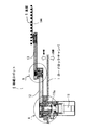
次に、ロードロックチャンバ1に配設された移載ロボット6、すなわち半導体製造装置に搭載されて用いられる移載ロボット6について、さらに詳しく説明する。この移載ロボット6が本発明に係る移載ロボットの一具体例を示すものである。図2は本発明に係る移載ロボットの概略構成例を示す断面図であり、図3および図4はその要部構成例を示す断面図である。
【0018】
図2に示すように、ここで説明する移載ロボット6は、水平多関節アームの先端部に基板5の支持部としてのフォークを備えて構成されたものである。具体的には、大別すると、移載ロボット6の駆動源として機能する例えば減速機付きの駆動モータ11と、その駆動モータ11の出力軸11aを中心にして回動自在に配された第一の水平アーム12と、その第一の水平アーム12の回動先端側に回動自在に配された第二の水平アーム13と、その第二の水平アーム13の回動先端側に配されたフォーク14と、から構成されている。そして、そのフォーク14上に基板5を載置し得るようになっている。
【0019】
これらのうち、駆動モータ11は、ロードロックチャンバ1の室外(大気側)に位置するように配設されている。また、第一および第二の水平アーム12,13とフォーク14は、ロードロックチャンバ1の室内(真空側)に位置するように配設されている。さらに、第一および第二の水平アーム12,13は、外装パネルによって覆われた胴体を有しているとともに、その胴体内に例えばタイミングベルト、プーリ、ベアリングといった回動を実現するための機構部品が配されている。
【0020】
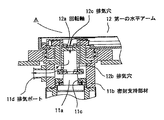
ところで、このような構成の移載ロボット6において、駆動モータ11と第一の水平アーム12との間、すなわち移載ロボット6の第一関節部Aでは、図3に示すように、駆動モータ11の出力軸11aとその駆動モータ11の密封支持部材11bとの間に密閉シール11cが設けられているとともに、密封支持部材11bに排気ポート11dが設けられており、その排気ポート11dに排気ポンプ3へ繋がる接続経路2が接続されるようになっている。また、駆動モータ11の出力軸11aに軸着された中空の回転軸12aには、その中空部を排気ポート11dが設けられた密封支持部材11bの内部空間と連通させるための排気穴12bと、同中空部を第一の水平アーム12の胴体内の空間と連通させるための排気穴12cが設けられている。
【0021】
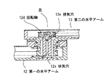
一方、第一の水平アーム12と第二の水平アーム13との間、すなわち移載ロボット6の第二関節部Bでは、図4に示すように、第一の水平アーム12と第二の水平アーム13とを回動自在に支持するための回転軸12dに、第一の水平アーム12の胴体内の空間と第二の水平アーム13の胴体内の空間とを互いに連通させるための排気穴12eが設けられている。
【0022】
なお、移載ロボット6における他の構成(例えば、各アーム12,13の胴体内に設けられた機構部品)については、従来と略同様であり、公知技術を用いて実現すればよいため、ここではその説明を省略する。
【0023】
次に、以上のように構成された半導体製造装置、特にその半導体製造装置に搭載された移載ロボット6の動作例について説明する。例えば、未処理の基板5を移載する場合であれば、EFEM内の移載ロボットが、大気開放状態のロードロックチャンバ1内のバッファ台上に当該基板5を一旦載置する。そして、その後は、ロードロックチャンバ1の第一および第二のゲートドアを閉じて、そのロードロックチャンバ1内を減圧状態にする。
【0024】
ただし、ロードロックチャンバ1の内部を減圧状態にするのにあたっては、先ず、第三のバルブ9を閉じた後、排気ポンプ3に吸引動作をさせつつ、第二のバルブ7の切り換えを行う。これにより、移載ロボット6の胴体内のみを減圧状態にする。すなわち、ロードロックチャンバ1内が減圧状態となるのに先立って、排気ポート11dからの排気により移載ロボット6の各アーム12,13の胴体内を減圧状態とする。
【0025】
そして、制御部からの指示に従いつつ、第二のバルブ7の切り換えから所定時間経過後に、第一のバルブ4の切り換えを行う。これにより、ロードロックチャンバ1内についてもプロセスチャンバ内と同様の減圧状態になる。つまり、ロードロックチャンバ1の内部が大気開放状態から減圧状態へ遷移する。なお、各バルブ4,7,9の切り換えの時間差については、排気ポンプ3の吸引能力や各アーム12,13の胴体内の容量等を基に、各アーム12,13の胴体内が十分に減圧状態となる時間を予め決定しておき、その決定結果を上記の所定時間として制御部にプログラミングしておけばよい。
【0026】
ところで、第一のバルブ4を切り換えて、ロードロックチャンバ1内を大気開放状態から減圧状態へ遷移させようとする際には、既に移載ロボット6の各アーム12,13の胴体内の空間は、ロードロックチャンバ1の室内空間よりも圧力が低い状態となっている。つまり、ロードロックチャンバ1内を排気ポンプ3で吸引し、そのロードロックチャンバ1内が大気開放状態から減圧状態へ遷移する場合であっても、移載ロボット6の胴体内がその周囲(ロードロックチャンバ1内)の空間に比べて徐々に陽圧になってしまうことがない。したがって、移載ロボット6の胴体内からロードロックチャンバ1内へ、パーティクル、オイル、ミスト等といった塵埃が流出してしまうことはない。
【0027】
そして、ロードロックチャンバ1内が減圧状態になると、第一のゲートドアを開けてロードロックチャンバ1とプロセスチャンバとの間を連通させ、そのロードロックチャンバ1内の移載ロボット6が、バッファ台上の基板5をフォーク上に載置してプロセスチャンバ方向に向かって移送する。
【0028】
一方、処理済みの基板5を移載する場合には、従来と略同様に、移載ロボット6がプロセスチャンバ内から基板5を取り出してバッファ台上に一旦載置した後、第一のゲートドアを閉じてから第一のバルブ4を閉じた後、第三のバルブ9を開け、その後、第二のバルブ7の切り換えを行い、ロードロックチャンバ1内および移載ロボット6の胴体内を大気開放状態にする。つまり、ロードロックチャンバ1が大気開放状態となった後の一定期間、排気ポート11dからの排気により移載ロボット6の胴体内の減圧状態が維持されるようにする。このときの一定期間については、各アーム12,13の胴体内の容量等を基に予め決定しておき、その決定結果を制御部にプログラミングしておけばよい。このように、第二バルブ7を開いた状態で排気ポンプ3で引きながら移載ロボット6の内部を徐々に陽圧にすることで、ロードロックチャンバ1内あるいは移載ロボット6内にある塵埃が回り込むのを防止し、最終的には第二のバルブ7を閉じて大気開放状態の圧力とする。そして、第二のゲートドアを開けると、EFEM内の移載ロボットがバッファ台上の基板5をフォーク上に載置してEFEM内に運び入れる。
【0029】
以上のように、本実施形態で説明した半導体製造装置および移載ロボット6によれば、ロードロックチャンバ1の内部が大気開放状態から減圧状態へ遷移する場合であっても、移載ロボット6の胴体内を減圧状態にし得るので、その胴体内が周囲の空間に比べて陽圧になってしまうことがない。したがって、移載ロボット6の胴体内からロードロックチャンバ1内に塵埃が流出してしまうことがなく、ロードロックチャンバ1内の基板5が汚染されるのを防止することができる。
【0030】
さらには、移載ロボット6の胴体内を減圧状態にすることによって塵埃の流出を防止しているので、例えば第一または第二関節部A,Bに対するシール処理等を厳重に施さなくても、塵埃の流出防止が実現可能となる。しかも、シール処理等によって移載ロボット6の構成の複雑化やそれに伴う大型化を招いてしまうこともないので、移載ロボット6の小型化や低コスト化等の実現も非常に容易となる。
【0031】
その上、本実施形態で説明した移載ロボット6は、減圧状態と大気開放状態とが遷移する環境下において用いて好適なものである。すなわち、本実施形態で説明した移載ロボット6を用いれば、減圧環境下と大気環境下とで兼用可能であることから、減圧環境下用のロボットと大気環境下用のロボットとをそれぞれ個別に用意する必要がない。したがって、例えば従来であれば二つのロボットが必要な場合であっても、減圧環境下と大気環境下とで兼用可能である一つの移載ロボット6を用意すれば済むので、被処理物である基板5の搬送を効率よく短時間で行うことができる。さらには、これに伴って、消費電力等の低減(省エネルギー化)が図れるとともに、半導体製造装置の小型化や低コスト化等の実現も非常に容易となる。
【0032】
また、本実施形態で説明した半導体製造装置および移載ロボット6によれば、ロードロックチャンバ1内が減圧状態となるのに先立って、移載ロボット6の胴体内を減圧状態にするようになっている。すなわち、先ず移載ロボット6の胴体内を減圧状態とし、その後にロードロックチャンバ1内を減圧状態にするというシーケンスを採用している。したがって、ロードロックチャンバ1内を減圧状態とする際には、既に移載ロボット6の胴体内が減圧状態となっていることから、確実に塵埃の流出を防止することができ、ロードロックチャンバ1内の基板5の汚染を防止する上で非常に有効なものとなる。
【0033】
なお、本実施形態では、移載ロボット6として水平多関節アームを備えたものを例に挙げて説明したが、これは単なる一例に過ぎず、一軸型、XY直交型、三次元方向に動作可能な多関節アーム型等、他の形式のものであっても全く同様に適用可能であることは勿論である。
【0034】
【発明の効果】
以上に説明したように、本発明に係る半導体製造装置によれば、移載ロボットの胴体内を減圧状態にした後にロードロックチャンバ内を減圧状態にするので、ロードロックチャンバの内部が大気開放状態から減圧状態へ遷移する場合であっても、移載ロボットの胴体内がその周囲の空間に比べて陽圧になってしまうことがない。また、移載ロボットの胴体内部の減圧状態を保ちつつロードロックチャンバの内部を大気開放状態にするので、ロードロックチャンバの内部が減圧状態から大気開放状態へ遷移する場合であっても、移載ロボットの内部が陽圧になる。したがって、減圧状態と大気開放状態とを遷移する環境下であっても、移載ロボットからの塵埃の流出を無くし、被処理物である基板の汚染を防止することができる。また、減圧状態と大気開放状態とを遷移する環境下であっても、同一の移載ロボットで基板の搬送を行うことが可能となるので、当該搬送を効率よく短時間で行うことができるようになる。
【図面の簡単な説明】
【図1】 本発明に係る半導体製造装置の要部構成の一例を示す説明図である。
【図2】 本発明に係る半導体製造装置における移載ロボットの概略構成例を示す断面図である。
【図3】 本発明に係る半導体製造装置における移載ロボットの要部構成例を示す断面図(その1)であり、図2の移載ロボットにおけるA部の拡大断面を示す図である。
【図4】 本発明に係る半導体製造装置における移載ロボットの要部構成例を示す断面図(その2)であり、図2の移載ロボットにおけるB部の拡大断面を示す図である。[0001]
BACKGROUND OF THE INVENTION
The present invention relates to a semiconductor manufacturing apparatus used in a semiconductor device manufacturing process.
[0002]
[Prior art]
In general, in a semiconductor device manufacturing process, for example, dry etching processing or RIE (Reactive Ion Etching) processing is performed on a wafer, a liquid crystal substrate, a quartz substrate, a glass substrate, and the like (hereinafter simply referred to as “substrate”). As described above, the treatment is often performed in a reduced pressure state such as a vacuum or a predetermined gas environment.
[0003]
As a semiconductor manufacturing apparatus for performing processing in a reduced pressure state, a process chamber serving as a processing chamber (a reduced pressure chamber chamber) in a reduced pressure state, and connected to the process chamber, both in a reduced pressure (vacuum) state and in an open atmosphere state And a load front chamber (hereinafter referred to as “EFEM”) that is connected to the load lock chamber and is open to the atmosphere. In this semiconductor manufacturing apparatus, a first gate door that can be opened and closed is provided between the process chamber and the load lock chamber, and a second gate door that can be opened and closed is provided between the load lock chamber and the EFEM. Yes. In the EFEM, for example, a transfer robot configured with a fork as a support portion of a substrate is disposed at the tip of a horizontal articulated arm, and the transfer robot is, for example, SEMI (Semiconductor Equipments and Materials are taken out from a substrate storage container called “FOUP (Front Opening Unified Pod)” in the standard and stored in the FOUP. On the other hand, a transfer robot for transferring a substrate is also provided in the load lock chamber. Further, a buffer base for temporarily placing the substrate is provided in the load lock chamber before and after the substrate transfer direction of the transfer robot.
[0004]
In the semiconductor manufacturing apparatus having such a configuration, the transfer robot in the EFEM and the transfer robot in the load lock chamber each perform the following operations.
For example, in the case of transferring an unprocessed substrate, first, while the transfer robot in the EFEM is taking out the substrate from the FOUP, the inside of the load lock chamber is opened to the atmosphere similar to that in the EFEM. . When the load lock chamber is opened to the atmosphere, the second gate door is opened to allow communication between the load lock chamber and the EFEM. In this state, the transfer robot in the EFEM temporarily places the substrate taken out from the FOUP on the buffer table in the load lock chamber. Thereafter, the second gate door is closed and the pressure is reduced by a vacuum pump, and the inside of the load lock chamber is brought into a reduced pressure (vacuum) state similar to that in the process chamber. When the pressure inside the load lock chamber is reduced, the first gate door is opened to allow communication between the load lock chamber and the process chamber, and the transfer robot in the load lock chamber forks the substrate on the buffer table. It is placed on top and transferred toward the process chamber. Conversely, when transferring a processed substrate, the substrate is temporarily placed on the buffer table by the transfer robot in the load lock chamber, and the load lock chamber is opened to the atmosphere. After that, open the second gate door. In this state, the transfer robot in the EFEM places the substrate on the buffer table on the fork and carries it into the EFEM (for example, see Patent Document 1).
[0005]
[Patent Document 1]
JP-A-2003-45933 gazette
[Problems to be solved by the invention]
However, the conventional semiconductor manufacturing apparatus described above and the transfer robot mounted on the semiconductor manufacturing apparatus have the following problems . That is, in the semiconductor manufacturing apparatus described above, the inside of the load lock chamber transitions between a reduced pressure state and an air release state. Therefore, at the time of transition from the open state to the decompressed state, as the inside of the load lock chamber is exhausted, the body of the transfer robot disposed in the load lock chamber is surrounded by the surroundings (inside the load lock chamber). It gradually becomes positive pressure compared to the space. This is not preferable because it causes the outflow of dust such as particles, oil, and mist from the body of the transfer robot into the load lock chamber.
[0007]
In this regard, it is conceivable that the transfer robot is subjected to a sealing process or the like so as to correspond to the operation in the reduced pressure state. However, in that case, there is a concern that the configuration of the transfer robot may become complicated and the size thereof may increase due to, for example, a sealing process for a movable part such as a multi-joint arm. In addition, when using in an environment where the reduced pressure state and the open air state are transitioned instead of being always used in a reduced pressure state, it is avoided that the body of the transfer robot becomes a positive pressure compared to the surroundings. Therefore, even if a sealing process or the like is performed, it is not always possible to reliably prevent the outflow of dust.
[0008]
Accordingly, the present invention provides a semiconductor manufacturing apparatus capable of preventing the outflow of dust even in an environment where a reduced pressure state and an open air state are transitioned, and efficiently transporting a substrate as a processing object in a short time. The purpose is to provide.
[0009]
[Means for Solving the Problems]
The present invention is a semiconductor manufacturing apparatus devised to achieve the above object. That is, in a load lock chamber provided with an openable / closable first door leading to the decompression process chamber and an openable / closable second door leading to the atmosphere release chamber, the workpiece is disposed between the decompression process chamber and the atmosphere release chamber. A transfer robot for transferring and receiving, communicating with the exhaust path having the first valve in the load lock chamber, communicating with the exhaust path having the second valve in the transfer robot, The exhaust path having the first valve and the exhaust path having the second valve are connected to one exhaust pump, and the load lock chamber having the third valve is further decompressed. communicated the intake path back open to the atmosphere from the first valve, through the exhaust gas by opening and closing switching and exhaust pump of the second valve and the third valve, sealed A semiconductor manufacturing apparatus configured to be able to switch between a vacuum state and an open state to the inside of a lock chamber, wherein the transfer robot has a first body having a body covered with an exterior panel. An arm and a second arm, and a sealing support member for supporting the arm and the second arm, each of which is provided with an exhaust hole in which the first arm and the second arm are movable so that the body is decompressed. The exhaust port is provided in the sealing support member and communicated with the exhaust path provided with the second valve, and when the interior of the load lock chamber is changed from the open state to the decompressed state, the third valve is switched to the closed state. The second valve is switched to the open state, and after a predetermined time has elapsed, the first valve is switched to the open state to reduce the pressure inside the body of the transfer robot. The inside of the load lock chamber in a reduced pressure state, upon open to the atmosphere inside the load lock chamber from the vacuum state, switches the first valve to the closed state, it switches the third valve in the open state, after a predetermined time has elapsed By switching the second valve to the closed state, the inside of the load lock chamber is opened to the atmosphere while maintaining the decompressed state inside the body of the transfer robot.
[0011]
According to the semiconductor manufacturing apparatus having the above configuration, the body of the transfer robot can be in a reduced pressure state. Here, the reduced pressure state means a state in a space filled with a gas having a pressure lower than the normal atmospheric pressure, and a vacuum state (a low vacuum state of 10 2 Pa or higher and a high vacuum state of 10 −10 Pa or lower). Is also included. Therefore, even if the inside of the load lock chamber is changed from the open state to the decompressed state , the load lock chamber can be decompressed after the body of the transfer robot is decompressed prior to this. The body of the transfer robot does not gradually become positive pressure compared to the surrounding space (inside the load lock chamber). Even when the inside of the load lock chamber is changed from the decompressed state to the open state to the atmosphere, the inside of the load lock chamber is kept open to the atmosphere while keeping the decompressed state inside the body of the transfer robot. The inside of the loading robot gradually becomes positive pressure.
[0012]
DETAILED DESCRIPTION OF THE INVENTION
A semiconductor manufacturing apparatus according to the present invention will be described below with reference to the drawings.
[0013]
First, a semiconductor manufacturing apparatus according to the present invention will be described. FIG. 1 is an explanatory view showing an example of a main configuration of a semiconductor manufacturing apparatus according to the present invention. The semiconductor manufacturing apparatus described here is for performing processing in a reduced pressure state, and includes a load lock chamber 1 serving as a pre-processing chamber (depressurized preliminary chamber). The load lock chamber 1 is disposed between the process chamber and the EFEM, and includes a first door that can be opened and closed to the process chamber and a second door that can be opened and closed to the EFEM (however, , Both not shown).
[0014]
Further, the load lock chamber 1 is connected to an exhaust pump 3 via a
[0015]
Further, the load lock chamber 1 is provided with a transfer robot 6 for transferring the substrate 5 as the object to be processed between the process chamber and the EFEM. This transfer robot 6 is also connected to the exhaust pump 3 via the
On the
[0016]
These first to third valves 4, 7, 9 are composed of, for example, electromagnetic solenoid valves, and are switched between a decompression state and an atmospheric release state in accordance with an instruction from a control unit (not shown). Note that the control unit may be configured by a microprocessor or the like in which the operation timings of the first and second valves 4 and 7 are programmed in advance.
[0017]
Next, the transfer robot 6 disposed in the load lock chamber 1, that is, the transfer robot 6 mounted and used in the semiconductor manufacturing apparatus will be described in more detail. This transfer robot 6 shows a specific example of the transfer robot according to the present invention. FIG. 2 is a cross-sectional view showing a schematic configuration example of a transfer robot according to the present invention, and FIGS.
[0018]
As shown in FIG. 2, the transfer robot 6 described here includes a fork as a support portion of the substrate 5 at the tip of the horizontal articulated arm. Specifically, roughly divided, for example, a
[0019]
Of these, the
[0020]
By the way, in the transfer robot 6 having such a configuration, as shown in FIG. 3, the
[0021]
On the other hand, between the first
[0022]
Note that other configurations of the transfer robot 6 (for example, mechanical parts provided in the bodies of the
[0023]
Next, an operation example of the semiconductor manufacturing apparatus configured as described above, particularly the transfer robot 6 mounted on the semiconductor manufacturing apparatus will be described. For example, if an unprocessed substrate 5 is to be transferred, the transfer robot in the EFEM temporarily places the substrate 5 on the buffer table in the load lock chamber 1 in the open atmosphere. After that, the first and second gate doors of the load lock chamber 1 are closed, and the inside of the load lock chamber 1 is brought into a reduced pressure state.
[0024]
However, in order to make the inside of the load lock chamber 1 in a reduced pressure state, first, the third valve 9 is closed, and then the second valve 7 is switched while the exhaust pump 3 is performing a suction operation. As a result, only the body of the transfer robot 6 is decompressed. That is, prior to the load lock chamber 1 being depressurized, the bodies of the
[0025]
Then, the first valve 4 is switched after a predetermined time has elapsed since the switching of the second valve 7 while following the instruction from the control unit. As a result, the pressure in the load lock chamber 1 is reduced as in the process chamber. That is, the inside of the load lock chamber 1 transitions from the open state to the reduced pressure state. The time difference between the switching of the valves 4, 7, 9 is sufficiently reduced in the body of each
[0026]
By the way, when the first valve 4 is switched to make the inside of the load lock chamber 1 transition from the atmospheric release state to the decompression state, the space in the body of each
[0027]
When the pressure inside the load lock chamber 1 is reduced, the first gate door is opened to allow communication between the load lock chamber 1 and the process chamber, and the transfer robot 6 in the load lock chamber 1 is placed on the buffer table. The substrate 5 is placed on the fork and transferred toward the process chamber.
[0028]
On the other hand, when the processed substrate 5 is transferred, the transfer robot 6 removes the substrate 5 from the process chamber and temporarily places it on the buffer table, after which the first gate door is opened. After the first valve 4 is closed, the third valve 9 is opened, and then the second valve 7 is switched, and the load lock chamber 1 and the body of the transfer robot 6 are opened to the atmosphere. To. That is, the decompressed state in the body of the transfer robot 6 is maintained by exhaust from the exhaust port 11d for a certain period after the load lock chamber 1 is opened to the atmosphere. The predetermined period at this time may be determined in advance based on the capacity of the arms of the
[0029]
As described above, according to the semiconductor manufacturing apparatus and the transfer robot 6 described in the present embodiment, even if the inside of the load lock chamber 1 is changed from the open air state to the reduced pressure state, the transfer robot 6 Since the body can be in a reduced pressure state, the body does not become a positive pressure compared to the surrounding space. Therefore, dust does not flow out from the body of the transfer robot 6 into the load lock chamber 1, and the substrate 5 in the load lock chamber 1 can be prevented from being contaminated.
[0030]
Furthermore, since the outflow of dust is prevented by putting the body of the transfer robot 6 in a reduced pressure state, for example, even if the sealing process or the like for the first or second joint portions A and B is not strictly performed, It is possible to prevent the outflow of dust. In addition, since the configuration of the transfer robot 6 is not complicated and does not increase in size due to the sealing process or the like, it is very easy to reduce the size and cost of the transfer robot 6.
[0031]
In addition, the transfer robot 6 described in the present embodiment is suitable for use in an environment in which a reduced pressure state and an air release state transition. That is, if the transfer robot 6 described in the present embodiment is used, it can be used in both a reduced pressure environment and an atmospheric environment. Therefore, the robot for the reduced pressure environment and the robot for the atmospheric environment are individually provided. There is no need to prepare. Therefore, for example, even if two robots are conventionally required, it is only necessary to prepare one transfer robot 6 that can be used in both a reduced pressure environment and an atmospheric environment. The substrate 5 can be transported efficiently and in a short time. Further, along with this, power consumption and the like can be reduced (energy saving), and the semiconductor manufacturing apparatus can be very easily reduced in size and cost.
[0032]
Further, according to the semiconductor manufacturing apparatus and the transfer robot 6 described in the present embodiment, the body of the transfer robot 6 is put into a reduced pressure state before the load lock chamber 1 is put into a reduced pressure state. ing. That is, a sequence is adopted in which the body of the transfer robot 6 is first decompressed and then the load lock chamber 1 is decompressed. Accordingly, when the inside of the load lock chamber 1 is brought into the decompressed state, the body of the transfer robot 6 is already in the decompressed state, so that the outflow of dust can be reliably prevented. This is very effective in preventing contamination of the inner substrate 5.
[0033]
In this embodiment, the transfer robot 6 having a horizontal articulated arm has been described as an example. However, this is merely an example, and the transfer robot 6 can operate in a single axis type, an XY orthogonal type, and a three-dimensional direction. Of course, other types such as a multi-joint arm type can be applied in exactly the same manner.
[0034]
【The invention's effect】
As described above, according to the semiconductor manufacturing apparatus according to the present invention, since the load lock chamber is decompressed after the body of the transfer robot is decompressed, the interior of the load lock chamber is open to the atmosphere. Even in the case of transition from a reduced pressure state to a negative pressure state, the body of the transfer robot does not become a positive pressure compared to the surrounding space. In addition, since the inside of the load lock chamber is opened to the atmosphere while maintaining the reduced pressure state inside the body of the transfer robot, the transfer is performed even when the inside of the load lock chamber is changed from the reduced pressure state to the open atmosphere state. The inside of the robot becomes positive pressure. Therefore, even under an environment where a reduced pressure state and an open air state are transitioned, the outflow of dust from the transfer robot can be eliminated, and contamination of the substrate as the object to be processed can be prevented. In addition, even in an environment where a reduced pressure state and an open air state are transitioned, the same transfer robot can transport the substrate, so that the transport can be performed efficiently and in a short time. become.
[Brief description of the drawings]
FIG. 1 is an explanatory diagram showing an example of a main configuration of a semiconductor manufacturing apparatus according to the present invention.
FIG. 2 is a cross-sectional view showing a schematic configuration example of a transfer robot in a semiconductor manufacturing apparatus according to the present invention.
3 is a sectional view (No. 1) showing a configuration example of a main part of a transfer robot in a semiconductor manufacturing apparatus according to the present invention, and is an enlarged cross-sectional view of a part A in the transfer robot of FIG. 2;
4 is a sectional view (No. 2) showing a configuration example of a main part of a transfer robot in the semiconductor manufacturing apparatus according to the present invention, and is an enlarged cross-sectional view of a part B in the transfer robot of FIG.
Claims (1)
前記ロードロックチャンバに第一のバルブを備えた排気用経路と連通させ、
前記移載ロボットに第二のバルブを備えた排気用経路を連通させ、
前記第一のバルブを備えた排気用経路と前記第二のバルブを備えた排気用経路とを1台の排気ポンプに接続させ、
さらに前記ロードロックチャンバに第三のバルブを備えたロードロックチャンバを減圧状態から大気開放状態にもどす吸気用経路を連通させ、
前記第一のバルブ、前記第二のバルブおよび前記第三のバルブの開閉切り換え並びに前記排気ポンプによる排気を通じて、密封された前記ロードロックチャンバの内部を減圧状態にするか、あるいは大気開放状態にするかを切り換え得るように構成された半導体製造装置であって、
前記移載ロボットは、外装パネルによって覆われた胴体を有する第一アームおよび第二アームと、これらを支持する密封支持部材とを備えており、
前記第一アームおよび前記第二アームを可動可能にする回転軸のそれぞれに排気穴を設け、前記胴体内を減圧状態にするための排気ポートを前記密封支持部材に設けて前記第二のバルブを備えた排気用経路に連通させ、
前記ロードロックチャンバの内部を大気開放状態から減圧状態にするにあたり、前記第三のバルブを閉状態に切り換え、前記第二のバルブを開状態に切り換え、所定時間経過後、前記第一のバルブを開状態に切り換えることにより、前記移載ロボットの胴体内部を減圧状態にした後に、前記ロードロックチャンバの内部を減圧状態にし、
前記ロードロックチャンバの内部を減圧状態から大気開放状態にするにあたり、前記第一のバルブを閉状態に切り換え、前記第三のバルブを開状態に切り換え、所定時間経過後、前記第二のバルブを閉状態に切り換えることにより、前記移載ロボットの胴体内部の減圧状態を保ちつつ、前記ロードロックチャンバの内部を大気開放状態にする
ことを特徴とする半導体製造装置。An object to be processed between the decompression process chamber and the atmosphere release chamber in a load lock chamber having a first door that can be opened and closed to the decompression process chamber and a second door that can be opened and closed to the atmosphere release chamber. A transfer robot is installed to send and receive
Communicating with an exhaust path comprising a first valve in the load lock chamber;
The transfer robot is connected to an exhaust path having a second valve,
Connecting the exhaust path with the first valve and the exhaust path with the second valve to one exhaust pump;
Further, the intake passage for returning the load lock chamber having the third valve to the load lock chamber from the decompressed state to the open state to the atmosphere is communicated ,
The inside of the sealed load lock chamber is brought into a decompressed state or opened to the atmosphere through opening / closing switching of the first valve, the second valve and the third valve and exhausting by the exhaust pump. A semiconductor manufacturing apparatus configured to be able to switch between,
The transfer robot includes a first arm and a second arm having a body covered with an exterior panel, and a sealing support member that supports them.
An exhaust hole is provided in each of the rotating shafts that allow the first arm and the second arm to move, and an exhaust port for reducing the pressure inside the body is provided in the sealing support member. Communicate with the exhaust path
When the inside of the load lock chamber is changed from the open state to the decompressed state, the third valve is switched to the closed state, the second valve is switched to the open state, and after the predetermined time has elapsed, the first valve is By switching to an open state, the inside of the body of the transfer robot is brought into a decompressed state, and then the inside of the load lock chamber is brought into a decompressed state,
When the inside of the load lock chamber is changed from the reduced pressure state to the atmospheric release state, the first valve is switched to the closed state, the third valve is switched to the opened state, and after the predetermined time has elapsed, the second valve is By switching to the closed state, the inside of the load lock chamber is opened to the atmosphere while maintaining the decompressed state inside the body of the transfer robot.
Priority Applications (1)
| Application Number | Priority Date | Filing Date | Title |
|---|---|---|---|
| JP2003182567A JP4570852B2 (en) | 2003-06-26 | 2003-06-26 | Semiconductor manufacturing equipment |
Applications Claiming Priority (1)
| Application Number | Priority Date | Filing Date | Title |
|---|---|---|---|
| JP2003182567A JP4570852B2 (en) | 2003-06-26 | 2003-06-26 | Semiconductor manufacturing equipment |
Publications (2)
| Publication Number | Publication Date |
|---|---|
| JP2005019684A JP2005019684A (en) | 2005-01-20 |
| JP4570852B2 true JP4570852B2 (en) | 2010-10-27 |
Family
ID=34182915
Family Applications (1)
| Application Number | Title | Priority Date | Filing Date |
|---|---|---|---|
| JP2003182567A Expired - Fee Related JP4570852B2 (en) | 2003-06-26 | 2003-06-26 | Semiconductor manufacturing equipment |
Country Status (1)
| Country | Link |
|---|---|
| JP (1) | JP4570852B2 (en) |
Families Citing this family (4)
| Publication number | Priority date | Publication date | Assignee | Title |
|---|---|---|---|---|
| JP4496541B2 (en) * | 2005-05-25 | 2010-07-07 | 株式会社安川電機 | Internal pressure explosion-proof system and scavenging method thereof |
| JP5465979B2 (en) * | 2009-10-26 | 2014-04-09 | 東京エレクトロン株式会社 | Semiconductor manufacturing equipment |
| KR102139613B1 (en) * | 2018-08-31 | 2020-07-30 | 세메스 주식회사 | Apparatus for transfer a substrate and apparatus for treating a substrate |
| JP6877480B2 (en) * | 2019-04-09 | 2021-05-26 | 株式会社荏原製作所 | A recording medium for storing a transfer device, a work processing device, a control method for the transfer device, and a program. |
Family Cites Families (6)
| Publication number | Priority date | Publication date | Assignee | Title |
|---|---|---|---|---|
| JPS6248485A (en) * | 1985-08-29 | 1987-03-03 | フアナツク株式会社 | Industrial joint type robot |
| JPH02185391A (en) * | 1989-01-11 | 1990-07-19 | Sony Corp | Articulated robot |
| JPH09131680A (en) * | 1995-11-02 | 1997-05-20 | Tokyo Electron Ltd | Transfer device for vacuum chamber |
| JPH09306972A (en) * | 1996-05-17 | 1997-11-28 | C Bui Res:Kk | Semiconductor manufacturing equipment |
| JP3322146B2 (en) * | 1996-12-27 | 2002-09-09 | 三菱電機株式会社 | Environmentally resistant industrial robot |
| JP2002270670A (en) * | 2001-12-25 | 2002-09-20 | Tokyo Electron Ltd | Vacuum processing equipment |
-
2003
- 2003-06-26 JP JP2003182567A patent/JP4570852B2/en not_active Expired - Fee Related
Also Published As
| Publication number | Publication date |
|---|---|
| JP2005019684A (en) | 2005-01-20 |
Similar Documents
| Publication | Publication Date | Title |
|---|---|---|
| TWI447838B (en) | Vacuum processing device | |
| JP2005079409A (en) | Substrate processing equipment | |
| KR20100031681A (en) | Compact board transport system with quick change robot | |
| JPH10144757A (en) | Substrate processing system | |
| JPH06211306A (en) | Substrate storage device | |
| JPH10242234A (en) | Manufacturing equipment | |
| JP4570852B2 (en) | Semiconductor manufacturing equipment | |
| WO2000042650A1 (en) | Vacuum treatment device | |
| JPWO2000042650A1 (en) | Vacuum Processing Equipment | |
| WO2006137370A1 (en) | Substrate transfer robot and processing apparatus | |
| JPH07122618A (en) | Vacuum processing device | |
| JP2006228808A (en) | Substrate transport apparatus, substrate transport method, and semiconductor manufacturing apparatus | |
| JP2004087781A (en) | Vacuum processing method and apparatus | |
| JP4432728B2 (en) | Vacuum processing equipment | |
| TW202144143A (en) | Robot, and substrate transportation system comprising same | |
| JPH10303099A (en) | Substrate processing equipment | |
| JP2011077288A (en) | Carrying device | |
| JPS61180423A (en) | Molecular beam epitaxy equipment | |
| JP2002270670A (en) | Vacuum processing equipment | |
| KR100849943B1 (en) | Buffer chamber for air pressure buffer between load lock chamber and process chamber | |
| JPH04184958A (en) | Taling-in and out method and device of content in carrier box | |
| JPH06275703A (en) | Vacuum treating apparatus | |
| JP2004071784A (en) | Clean transport device for substrate, and method for loading substrate thereon | |
| JP2009194261A (en) | Wafer conveyance system and wafer processor using wafer conveyance system | |
| JPH07297260A (en) | Cassette loading device |
Legal Events
| Date | Code | Title | Description |
|---|---|---|---|
| A621 | Written request for application examination |
Free format text: JAPANESE INTERMEDIATE CODE: A621 Effective date: 20060512 |
|
| A977 | Report on retrieval |
Free format text: JAPANESE INTERMEDIATE CODE: A971007 Effective date: 20081114 |
|
| A131 | Notification of reasons for refusal |
Free format text: JAPANESE INTERMEDIATE CODE: A131 Effective date: 20090331 |
|
| A521 | Request for written amendment filed |
Free format text: JAPANESE INTERMEDIATE CODE: A523 Effective date: 20090427 |
|
| RD02 | Notification of acceptance of power of attorney |
Free format text: JAPANESE INTERMEDIATE CODE: A7422 Effective date: 20091007 |
|
| RD04 | Notification of resignation of power of attorney |
Free format text: JAPANESE INTERMEDIATE CODE: A7424 Effective date: 20091015 |
|
| A521 | Request for written amendment filed |
Free format text: JAPANESE INTERMEDIATE CODE: A523 Effective date: 20091015 |
|
| A02 | Decision of refusal |
Free format text: JAPANESE INTERMEDIATE CODE: A02 Effective date: 20100126 |
|
| A521 | Request for written amendment filed |
Free format text: JAPANESE INTERMEDIATE CODE: A523 Effective date: 20100415 |
|
| A911 | Transfer to examiner for re-examination before appeal (zenchi) |
Free format text: JAPANESE INTERMEDIATE CODE: A911 Effective date: 20100426 |
|
| A131 | Notification of reasons for refusal |
Free format text: JAPANESE INTERMEDIATE CODE: A131 Effective date: 20100622 |
|
| A521 | Request for written amendment filed |
Free format text: JAPANESE INTERMEDIATE CODE: A523 Effective date: 20100706 |
|
| TRDD | Decision of grant or rejection written | ||
| A01 | Written decision to grant a patent or to grant a registration (utility model) |
Free format text: JAPANESE INTERMEDIATE CODE: A01 Effective date: 20100727 |
|
| A01 | Written decision to grant a patent or to grant a registration (utility model) |
Free format text: JAPANESE INTERMEDIATE CODE: A01 |
|
| A61 | First payment of annual fees (during grant procedure) |
Free format text: JAPANESE INTERMEDIATE CODE: A61 Effective date: 20100811 |
|
| FPAY | Renewal fee payment (event date is renewal date of database) |
Free format text: PAYMENT UNTIL: 20130820 Year of fee payment: 3 |
|
| R150 | Certificate of patent or registration of utility model |
Free format text: JAPANESE INTERMEDIATE CODE: R150 |
|
| R250 | Receipt of annual fees |
Free format text: JAPANESE INTERMEDIATE CODE: R250 |
|
| R250 | Receipt of annual fees |
Free format text: JAPANESE INTERMEDIATE CODE: R250 |
|
| LAPS | Cancellation because of no payment of annual fees |