JP4570044B2 - Portable electronic devices - Google Patents
Portable electronic devices Download PDFInfo
- Publication number
- JP4570044B2 JP4570044B2 JP2005192841A JP2005192841A JP4570044B2 JP 4570044 B2 JP4570044 B2 JP 4570044B2 JP 2005192841 A JP2005192841 A JP 2005192841A JP 2005192841 A JP2005192841 A JP 2005192841A JP 4570044 B2 JP4570044 B2 JP 4570044B2
- Authority
- JP
- Japan
- Prior art keywords
- cabinet
- heat
- electronic component
- heat conductive
- conductive sheet
- Prior art date
- Legal status (The legal status is an assumption and is not a legal conclusion. Google has not performed a legal analysis and makes no representation as to the accuracy of the status listed.)
- Expired - Fee Related
Links
Images


Description
本発明は、携帯電話機等の携帯型電子機器に関し、特にチューナ等の発熱部品を具えた携帯型電子機器に関するものである。 The present invention relates to a portable electronic device such as a cellular phone, and more particularly to a portable electronic device including a heat generating component such as a tuner.
近年、携帯電話機の小型化及び軽量化に伴って、携帯電話機に内蔵される電子部品の小型化が進んできている。
一方、この様な電子部品は、小型化すればするほど放熱に関して不利になるため、小型化の要求と併せて、動作時の発熱に対応できる良好な放熱構造が求められている。例えば、従来の携帯電話機の放熱構造は、携帯電話機の操作部を開閉可能に覆うカバー部材の内面に設けた放熱板と、該放熱板と熱源となる電子部品の間を接続する熱交換体とから構成される(特許文献1参照)。
On the other hand, such electronic components are disadvantageous in terms of heat dissipation as they are miniaturized. Therefore, in addition to the demand for miniaturization, a good heat dissipation structure that can cope with heat generation during operation is required. For example, a conventional mobile phone heat dissipating structure includes a heat dissipating plate provided on the inner surface of a cover member that covers the operation part of the mobile phone so as to be openable and closable, (Refer to Patent Document 1).
ところで、携帯電話機の多機能化に伴って、電話通信機能やメール送受信機能のみならず、テレビジョン放送やラジオ放送の受信機能を有するものが開発されている。テレビジョン放送やラジオ放送を受信するためのチューナアセンブリは、携帯電話機に内蔵される他の電子部品に比べて動作時の発熱量が大きいことが知られている。そこで、上記従来の放熱構造によって放熱を図ることが考えられる。 By the way, with the increase in the number of functions of mobile phones, not only a telephone communication function and a mail transmission / reception function but also a function having a reception function for television broadcasting and radio broadcasting has been developed. It is known that a tuner assembly for receiving television broadcasts and radio broadcasts generates a large amount of heat during operation as compared with other electronic components incorporated in a mobile phone. Therefore, it is conceivable to radiate heat using the conventional heat radiating structure.
しかしながら、上記従来の放熱構造において、熱交換体は熱源となる電子部品の近辺に配設されているに過ぎず、該電子部品と熱交換体とが互いに直接に接触していないため、電子部品から発生した熱は、空気層を介して熱交換体に伝えられることになる。このため、十分な放熱効果が得られず、この結果、チューナアセンブリに対向するキャビネットの一部の温度が局所的に上昇してしまうこととなり、キャビネットに触れたユーザが不快感をおぼえることがあった。
そこで本発明の目的は、電子部品の発熱によるキャビネットの局所的な温度上昇を効果的に抑制することが出来る携帯型電子機器を提供することである。
However, in the above-described conventional heat dissipation structure, the heat exchanger is only disposed in the vicinity of the electronic component that is a heat source, and the electronic component and the heat exchanger are not in direct contact with each other. The heat generated from the heat is transferred to the heat exchanger through the air layer. Therefore, a sufficient heat dissipation effect cannot be obtained, and as a result, the temperature of a part of the cabinet facing the tuner assembly locally rises, and the user who touches the cabinet may feel uncomfortable. It was.
Accordingly, an object of the present invention is to provide a portable electronic device that can effectively suppress a local temperature rise of a cabinet due to heat generation of an electronic component.
本発明に係る携帯型電子機器は、キャビネット(2)の内部に、通電によって発熱する電子部品とシート状の伝熱部材とを具え、該伝熱部材の一端が前記電子部品の表面に密着すると共に、該伝熱部材の他端が、前記電子部品よりも温度が低く且つ該電子部品から離間した位置に設置された他の構成部品の表面に密着している。 The portable electronic device according to the present invention includes an electronic component that generates heat when energized and a sheet-like heat transfer member inside the cabinet (2), and one end of the heat transfer member is in close contact with the surface of the electronic component. At the same time, the other end of the heat transfer member is in close contact with the surface of another component that is installed at a position lower in temperature than the electronic component and spaced from the electronic component.
上記本発明の携帯型電子機器において、前記電子部品から発生した熱は、伝熱部材を介して、該電子部品よりも温度が低く且つ該電子部品から離間した位置に設置された他の構成部品に熱伝導によって伝えられ、これによって該電子部品の温度が低下し、該電子部品に対向するキャビネット(2)の局所的な温度上昇が抑制される。
従って、上記本発明の携帯型電子機器によれば、電子部品の発熱によるキャビネット(2)の局所的な温度上昇を抑制することが出来る。
In the portable electronic device of the present invention, the heat generated from the electronic component is another component having a temperature lower than that of the electronic component and spaced from the electronic component via a heat transfer member. The temperature of the electronic component is lowered by this, and the local temperature rise of the cabinet (2) facing the electronic component is suppressed.
Therefore, according to the portable electronic device of the present invention, a local temperature rise of the cabinet (2) due to heat generation of the electronic component can be suppressed.
具体的構成において、前記キャビネット(2)は、一対のキャビネット半体(4)(5)を互いに接合して構成され、前記電子部品は、前記一対のキャビネット半体(4)(5)の内、一方のキャビネット半体(4)に取り付けられると共に、前記他の構成部品は、他方のキャビネット半体(5)に取り付けられており、前記伝熱部材は、前記一方のキャビネット半体(4)に取り付けられた第1熱伝導シート(71)と、前記他方のキャビネット半体(4)に取り付けられた第2熱伝導シート(72)とから構成され、第1熱伝導シート(71)の一端が前記電子部品の表面に密着すると共に、第2熱伝導シート(72)の一端が前記他の構成部品の表面に密着し、前記一対のキャビネット半体(4)(5)が互いに接合された状態で、前記第1熱伝導シート(71)の他端と第2熱伝導シート(72)との他端とが互いに重なり合って密着している。
具体的には、前記電子部品はチューナアセンブリ(42)であり、前記他の構成部品はバッテリーパック(61)である。
In a specific configuration, the cabinet (2) is formed by joining a pair of cabinet halves (4) and (5) to each other, and the electronic component is a member of the pair of cabinet halves (4) and (5). The other component is attached to the other cabinet half (5), and the heat transfer member is attached to the one cabinet half (4). And a second heat conductive sheet (72) attached to the other cabinet half (4), and one end of the first heat conductive sheet (71). Is in close contact with the surface of the electronic component, one end of the second heat conductive sheet (72) is in close contact with the surface of the other component, and the pair of cabinet halves (4) and (5) are joined together. In the state, the other end of the first heat conductive sheet (71) and the second heat conductive sheet (72) The other end overlaps and is in close contact with each other.
Specifically, the electronic component is a tuner assembly (42), and the other component is a battery pack (61).
該具体的構成によれば、前記電子部品と前記他の構成部品との間の放熱経路が、第1熱伝導シート(71)と第2熱伝導シート(72)の2枚の熱伝導シートによって形成されているため、キャビネット(2)を構成する2つのキャビネット半体(4)(5)の内、一方のキャビネット半体(4)に熱源である電子部品が設置されると共に、前記他の構成部品が他方のキャビネット半体(5)に設置されている場合にも、2つのキャビネット半体(4)(5)を完全に分離することが可能となる。 According to the specific configuration, the heat dissipation path between the electronic component and the other component is formed by two heat conductive sheets, the first heat conductive sheet (71) and the second heat conductive sheet (72). Therefore, of the two cabinet halves (4) and (5) constituting the cabinet (2), one of the cabinet halves (4) is provided with an electronic component as a heat source, and the other Even when the components are installed in the other cabinet half (5), the two cabinet halves (4) (5) can be completely separated.
又、2つのキャビネット半体(4)(5)を互いに接合した状態においては、第1熱伝導シート(71)の一端と第2熱伝導シート(72)の一端とが互いに重なり合って密着し、前記電子部品から発生した熱は、第1熱伝導シート(71)及び第2熱伝導シート(72)を介して、前記他の構成部品に伝えられることになる。
従って、上記本発明の折り畳み式携帯電話機によれば、組立性や修理時の作業性の悪化を招くことなく、簡易な構成で十分な放熱効果が得られる放熱構造が実現される。
In addition, in the state where the two cabinet halves (4) and (5) are joined to each other, one end of the first heat conductive sheet (71) and one end of the second heat conductive sheet (72) are overlapped and adhered to each other. The heat generated from the electronic component is transferred to the other components via the first heat conductive sheet (71) and the second heat conductive sheet (72).
Therefore, according to the foldable mobile phone of the present invention, a heat dissipation structure that achieves a sufficient heat dissipation effect with a simple configuration is realized without deteriorating workability during assembly and repair.
又、具体的構成において、前記一方のキャビネット半体(4)の内面には、メイン基板(41)が取り付けられると共に、前記電子部品は、該メイン基板(41)上に取り付けられたホルダ(43)内に設置されており、該電子部品が設置されるべきホルダ(43)の設置面には、弾性体からなる第1接圧パッド(73)が配備されると共に、該第1接圧パッド(73)と前記電子部品の間に、前記第1熱伝導シート(71)の一端が配備され、前記電子部品、第1熱伝導シート(71)の一端及び第1接圧パッド(73)は、該第1接圧パッド(73)が圧縮された状態で、前記ホルダ(43)の設置面と前記他方のキャビネット半体(5)の内面との間で狭圧されている。 In a specific configuration, a main board (41) is attached to the inner surface of the one cabinet half (4), and the electronic component is mounted on a holder (43) attached on the main board (41). ) And a first contact pressure pad (73) made of an elastic body is provided on the installation surface of the holder (43) where the electronic component is to be installed, and the first contact pressure pad One end of the first heat conductive sheet (71) is disposed between the electronic component, the electronic component, one end of the first heat conductive sheet (71), and the first contact pressure pad (73). The first contact pressure pad (73) is compressed between the installation surface of the holder (43) and the inner surface of the other cabinet half (5).
そして、前記メイン基板(41)上には、弾性体からなる第2接圧パッド(74)が配備されると共に、該第2接圧パッド(74)と前記他方のキャビネット半体(5)の内面との間には、前記第1熱伝導シート(71)の他端と前記第2熱伝導シート(72)の他端とが互いに重なり合って配備され、該両熱伝導シート(71)(72)の他端及び前記第2接圧パッド(74)は、該第2接圧パッド(74)が圧縮された状態で、前記他方のキャビネット半体(5)の内面と前記メイン基板(41)の間で狭圧されている。 A second contact pressure pad (74) made of an elastic body is provided on the main board (41), and the second contact pressure pad (74) and the other cabinet half (5) are arranged. Between the inner surface, the other end of the first heat conductive sheet (71) and the other end of the second heat conductive sheet (72) are arranged to overlap each other, and both the heat conductive sheets (71) (72) ) And the second contact pressure pad (74) in a state where the second contact pressure pad (74) is compressed, the inner surface of the other cabinet half (5) and the main board (41). It is narrowed between.
該具体的構成において、ホルダ(4)の設置面と前記他方のキャビネット半体(5)の内面との間隔は、組み立て誤差等によって若干変動することになるが、前記間隔の変動は、第1接圧パッド(73)の弾性変形により吸収されることになる。従って、前記電子部品と第1熱伝導シート(71)との密着状態は常に安定したものとなる。
同様に、メイン基板(41)と前記他方のキャビネット半体(5)の内面との間隔は、組み立て誤差等によって若干変動することになるが、前記間隔の変動は、第2接圧パッド(74)の弾性変形により吸収されることになる。従って、第1熱伝導シート(71)と第2熱伝導シート(72)との密着状態は常に安定したものとなる。
In this specific configuration, the interval between the installation surface of the holder (4) and the inner surface of the other cabinet half (5) will vary slightly due to assembly errors or the like. It is absorbed by the elastic deformation of the contact pressure pad (73). Therefore, the contact state between the electronic component and the first heat conductive sheet (71) is always stable.
Similarly, the distance between the main board (41) and the inner surface of the other cabinet half (5) varies slightly due to assembly errors or the like. ) Is absorbed by elastic deformation. Therefore, the contact state between the first heat conductive sheet (71) and the second heat conductive sheet (72) is always stable.
更に具体的構成において、前記第1熱伝導シート(71)は、前記第2熱伝導シート(72)を構成するシート材よりも熱伝導率の高いシート材から構成されている。 In a more specific configuration, the first heat conductive sheet (71) is made of a sheet material having a higher thermal conductivity than the sheet material constituting the second heat conductive sheet (72).
該具体的構成において、第1熱伝導シート(71)及び第2熱伝導シート(72)を構成するシート材の熱伝導率が高ければ高いほど、放熱効果は高くなるが、一般に熱伝導率の高いシート材は高価であるため、熱源である電子部品の発熱量等を考慮して十分な放熱効果が得られる場合には、該電子部品に直接に接触することのない第2熱伝導シート(72)を、第1熱伝導シート(71)を構成するシート材よりも熱伝導率の低い安価なシート材から構成することにより、コストダウンを図ることが出来る。 In the specific configuration, the higher the thermal conductivity of the sheet material constituting the first thermal conductive sheet (71) and the second thermal conductive sheet (72), the higher the heat dissipation effect. Since a high sheet material is expensive, when a sufficient heat dissipation effect is obtained in consideration of the heat generation amount of the electronic component that is a heat source, the second heat conductive sheet that does not directly contact the electronic component ( The cost can be reduced by configuring 72) from an inexpensive sheet material having a lower thermal conductivity than the sheet material constituting the first heat conductive sheet (71).
本発明に係る携帯型電子機器によれば、電子部品の発熱によるキャビネットの局所的な温度上昇を効果的に抑制することが出来る。 According to the portable electronic device according to the present invention, it is possible to effectively suppress a local temperature rise of the cabinet due to heat generation of the electronic component.
以下、本発明を折り畳み式携帯電話機に実施した形態につき、図面に沿って具体的に説明する。
図1に示す如く、本発明に係る折り畳み式携帯電話機は、第1キャビネット(1)と第2キャビネット(2)とをヒンジ機構(3)を介して互いに開閉可能に連結して構成される。
第1キャビネット(1)の表面には、液晶ディスプレイ(11)が配備されると共に、第2キャビネット(2)の表面には、複数の操作キー(21)〜(21)が配備されている。
DESCRIPTION OF THE PREFERRED EMBODIMENTS Embodiments of the present invention applied to a foldable mobile phone will be specifically described below with reference to the drawings.
As shown in FIG. 1, the foldable mobile phone according to the present invention is configured by connecting a first cabinet (1) and a second cabinet (2) to each other via a hinge mechanism (3) so as to be opened and closed.
A liquid crystal display (11) is provided on the surface of the first cabinet (1), and a plurality of operation keys (21) to (21) are provided on the surface of the second cabinet (2).
図2及び図3に示す如く、第2キャビネット(2)は、前面キャビネット半体(4)と背面キャビネット半体(5)とを互いに接合してなり、図3に示す如く、前面キャビネット半体(4)の内面には、メイン基板(41)が設置されている。
メイン基板(41)上には、テレビチューナアセンブリ(42)を保持すると共に該テレビチューナアセンブリ(42)に対するシールド機能を発揮するホルダ(43)が取り付けられており、該ホルダ(43)内に、テレビチューナアセンブリ(42)が設置されている。
ホルダ(43)のテレビチューナアセンブリ(42)が設置されるべき設置面には、後述する第1熱伝導シート(41)の一端が配備されており、該第1熱伝導シート(41)の他端が、前面キャビネット半体(4)内の中央部へ向けて伸びている。
2 and 3, the second cabinet (2) is formed by joining the front cabinet half (4) and the back cabinet half (5) to each other. As shown in FIG. A main board (41) is installed on the inner surface of (4).
On the main board (41), a holder (43) that holds the TV tuner assembly (42) and exhibits a shielding function for the TV tuner assembly (42) is attached, and in the holder (43), A TV tuner assembly (42) is installed.
One end of a first heat conductive sheet (41), which will be described later, is provided on the installation surface of the holder (43) where the TV tuner assembly (42) is to be installed. In addition to the first heat conductive sheet (41), The end extends toward the center of the front cabinet half (4).
又、背面キャビネット半体(5)の背面には、バッテリーパック(6)を収容するための収容室(52)が凹設されており、該収容室(52)の底面には、矩形状の開口(51)が開設されている。
図2に示す如く、背面キャビネット半体(5)内の中央部には、前面キャビネット半体(4)と背面キャビネット半体(5)とを互いに接合した状態において前記第1熱伝導シート(41)の他端と互いに重なることとなる位置に、後述する第2熱伝導シート(72)の一端が配備され、該第2熱伝導シート(72)の他端が、開口(51)の側部に開設されたスリット(53)を通して背面キャビネット半体(5)の外面に露出し、開口(52)を閉塞している。
A housing chamber (52) for housing the battery pack (6) is recessed in the rear surface of the rear cabinet half (5), and a rectangular shape is formed on the bottom surface of the housing chamber (52). An opening (51) is established.
As shown in FIG. 2, the first heat conductive sheet (41) is provided at the center of the back cabinet half (5) in a state where the front cabinet half (4) and the back cabinet half (5) are joined together. ) Is disposed at one end of the second heat conductive sheet (72), which will be described later, and the other end of the second heat conductive sheet (72) is connected to the side of the opening (51). It is exposed to the outer surface of the rear cabinet half (5) through the slit (53) opened in Fig. 5 and closes the opening (52).
更に、図3に示す如く、収容室(52)の底面には、品質表示ラベル(62)が貼り付けられ、該収容室(52)内にバッテリーパック(6)が収容されると共に、背面キャビネット半体(5)の背面にはバッテリーカバー(61)が取り付けられて、収容室(52)を閉塞している。 Further, as shown in FIG. 3, a quality label (62) is attached to the bottom surface of the storage chamber (52), the battery pack (6) is stored in the storage chamber (52), and the rear cabinet. A battery cover (61) is attached to the back surface of the half body (5) to close the accommodating chamber (52).
ところで、テレビチューナアセンブリ(42)は動作時の発熱量が大きいため、良好な放熱構造が必要となるが、本発明の折り畳み式携帯電話機においては、図4に示す如く、第1熱伝導シート(71)及び第2熱伝導シート(72)からなる放熱経路を介して、テレビチューナアセンブリ(42)と比較的熱容量の大きいバッテリーパック(6)とを互いに接続し、該放熱経路によってテレビチューナアセンブリ(42)の放熱構造を実現した。 By the way, since the TV tuner assembly (42) generates a large amount of heat during operation, a good heat dissipation structure is required. However, in the foldable mobile phone of the present invention, as shown in FIG. 71) and a second tuner plate (42) and a battery pack (6) having a relatively large heat capacity are connected to each other through a heat dissipation path comprising the second heat conductive sheet (72), and the TV tuner assembly ( 42) The heat dissipation structure was realized.
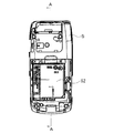
図5は、第2キャビネット(2)から図2及び図3に示すバッテリーカバー(61)及びバッテリーパック(6)を取り外した状態を示しており、図6は、図5のA−A線に沿う断面を示している。
図4及び図6に示す接合状態において、第1熱伝導シート(71)の一端は、テレビチューナアセンブリ(42)の発熱面に密着し、第2熱伝導シート(72)の一端が背面キャビネット(5)の外面に露出して、バッテリーパック(6)が設置されるべき収容室(52)の底面に密着している。
又、背面キャビネット(5)の内面に沿って伸びる第1熱伝導シート(71)の他端と、スリット(53)を通じて背面キャビネット(5)の内部に侵入し該背面キャビネット(5)の内面に沿って伸びる第2熱伝導シート(72)の他端とが、互いに重なり合って密着している。
尚、第1熱伝導シート(71)はグラファイトシートであり、第2熱伝導シート(72)は銅箔である。
FIG. 5 shows a state in which the battery cover (61) and the battery pack (6) shown in FIGS. 2 and 3 are removed from the second cabinet (2), and FIG. 6 shows a line AA in FIG. The cross section along is shown.
4 and 6, one end of the first heat conductive sheet (71) is in close contact with the heat generating surface of the TV tuner assembly (42), and one end of the second heat conductive sheet (72) is connected to the rear cabinet ( It is exposed on the outer surface of 5) and is in close contact with the bottom surface of the storage chamber (52) where the battery pack (6) should be installed.
Also, the other end of the first heat
The first heat conductive sheet (71) is a graphite sheet, and the second heat conductive sheet (72) is a copper foil.
図4及び図6に示す如く、ホルダ(43)のテレビチューナアセンブリ(42)が設置された設置面上には、第1熱伝導シート(71)の一端が配備されると共に、該第1熱伝導シート(71)の一端とホルダ(43)の設置面の間には、発泡ウレタン製の第1接圧パッド(73)が配備されている。
又、第2熱伝導シート(71)の一端が背面キャビネット半体(5)の外面に露出して、収容室(52)の底面を閉塞すると共に、他端がスリット(53)を通じて背面キャビネット半体(5)の内面に沿って伸びている。
メイン基板(41)上には、第1熱伝導シート(71)の他端と第2熱伝導シート(72)の他端とが互いに重なることとなる位置に、発泡ウレタン製の第2接圧パッド(74)が配備されている。
As shown in FIGS. 4 and 6, one end of the first heat conductive sheet (71) is disposed on the installation surface on which the TV tuner assembly (42) of the holder (43) is installed, and the first heat conduction sheet (71) is provided. A first contact pressure pad (73) made of urethane foam is disposed between one end of the conductive sheet (71) and the installation surface of the holder (43).
Also, one end of the second heat conductive sheet (71) is exposed on the outer surface of the rear cabinet half (5) to close the bottom surface of the storage chamber (52), and the other end is connected to the rear cabinet half through the slit (53). It extends along the inner surface of the body (5).
On the main substrate (41), the second contact pressure made of urethane foam is placed at a position where the other end of the first heat conductive sheet (71) and the other end of the second heat conductive sheet (72) overlap each other. A pad (74) is provided.
図6に示す接合状態において、テレビチューナアセンブリ(42)、第1熱伝導シート(71)の一端及び第1接圧パッド(73)は、該第1接圧パッド(73)が圧縮された状態で、ホルダ(43)の設置面と背面キャビネット半体(5)の内面との間に狭圧されている。
又、第1熱伝導シート(71)の他端、第2熱伝導シート(72)の他端及び第2接圧パッド(74)は、該第2接圧パッド(74)が圧縮された状態で、メイン基板(41)と背面キャビネット半体(5)の内面との間に狭圧されている。
In the joined state shown in FIG. 6, the television tuner assembly (42), one end of the first heat conductive sheet (71) and the first contact pressure pad (73) are in a state where the first contact pressure pad (73) is compressed. Thus, a pressure is applied between the installation surface of the holder (43) and the inner surface of the rear cabinet half (5).
Further, the other end of the first heat
第2キャビネット(2)の組み立て時において、ホルダ(4)の設置面と背面キャビネット半体(5)の内面との間隔は、組み立て誤差等によって若干変動することになるが、前記間隔の変動は、第1接圧パッド(73)の弾性変形により吸収され、該第1接圧パッド(73)の弾性反発力によって、テレビチューナアセンブリ(42)と第1熱伝導シート(71)との密着状態は常に安定したものとなる。
When assembling the second cabinet (2), the distance between the installation surface of the holder (4) and the inner surface of the rear cabinet half (5) will vary slightly due to assembly errors, etc. The first
同様に、メイン基板(41)と背面キャビネット半体(5)の内面との間隔は、組み立て誤差等によって若干変動することになるが、前記間隔の変動は、第2接圧パッド(74)の弾性変形により吸収され、該第2接圧パッド(74)の弾性反発力によって、第1熱伝導シート(71)と第2熱伝導シート(72)との密着状態は常に安定したものとなる。 Similarly, the interval between the main board (41) and the inner surface of the rear cabinet half (5) will slightly vary due to assembly errors, etc., but the variation in the interval will be caused by the second contact pressure pad (74). Absorbed by the elastic deformation, the contact state between the first heat conductive sheet (71) and the second heat conductive sheet (72) is always stable by the elastic repulsive force of the second contact pressure pad (74).
上記本発明の折り畳み式携帯電話機において、第1熱伝導シート(71)が前面キャビネット半体(4)に設置されると共に、第2熱伝導シート(72)が背面キャビネット半体(5)に設置されているので、修理等のために前面キャビネット半体(4)と背面キャビネット半体(5)とを分離した場合には、第1熱伝導シート(71)と第2熱伝導シート(72)とが互いに重なり合ったそれぞれの端部にて分離することになる。従って、図2及び図3に示す如く、前面キャビネット半体(4)と背面キャビネット半体(5)とを完全に分離した状態で、修理作業を行なうことが出来る。 In the foldable mobile phone of the present invention, the first heat conductive sheet (71) is installed in the front cabinet half (4) and the second heat conductive sheet (72) is installed in the rear cabinet half (5). Therefore, when the front cabinet half (4) and the back cabinet half (5) are separated for repair, etc., the first heat conduction sheet (71) and the second heat conduction sheet (72) Are separated from each other at the ends where they overlap each other. Therefore, as shown in FIGS. 2 and 3, repair work can be performed with the front cabinet half (4) and the back cabinet half (5) completely separated.
一方、接合状態においては、図4及び図6に示す如く、第1熱伝導シート(71)の一端と第2熱伝導シート(72)の一端とが互いに重なり合って密着し、テレビチューナアセンブリ(42)から発生した熱は、第1熱伝導シート(71)及び第2熱伝導シート(72)を介して、バッテリーパック(6)に伝えられることになる。
従って、上記本発明の折り畳み式携帯電話機によれば、組立性や修理時の作業性の悪化を招くことなく、簡易な構成で十分な放熱効果が得られる放熱構造が実現される。
上記本発明の折り畳み式携帯電話機のテレビチューナアセンブリ(42)及び背面キャビネット(2)の温度を実測したところ、テレビチューナアセンブリ(42)のピーク温度が3℃低下し、背面キャビネット(2)の局所的な温度上昇が抑制されることが明らかとなった。
On the other hand, in the joined state, as shown in FIGS. 4 and 6, one end of the first heat conductive sheet (71) and one end of the second heat conductive sheet (72) are overlapped and closely adhered to each other, and the TV tuner assembly (42 ) Is transmitted to the battery pack (6) through the first heat conductive sheet (71) and the second heat conductive sheet (72).
Therefore, according to the foldable mobile phone of the present invention, a heat dissipation structure that achieves a sufficient heat dissipation effect with a simple configuration is realized without deteriorating workability during assembly and repair.
When the temperature of the TV tuner assembly (42) and the back cabinet (2) of the foldable mobile phone of the present invention was measured, the peak temperature of the TV tuner assembly (42) decreased by 3 ° C, and the local temperature of the back cabinet (2) was reduced. It became clear that the typical temperature rise was suppressed.
尚、本発明の各部構成は上記実施の形態に限らず、特許請求の範囲に記載の技術的範囲内で種々の変形が可能である。例えば本実施例においては、十分な放熱効果が得られたため、第1熱伝導シート(71)としてグラファイトシートを用いると共に、グラファイトシートよりも安価で且つ熱伝導率の低い銅箔を第2熱伝導シート(72)として用いることにより、コストダウンを実現したが、第1熱伝導シート(71)及び第2熱伝導シート(72)の双方にグラファイトシートを採用することにより、更なる放熱効果の向上を図ることが出来る。 In addition, each part structure of this invention is not restricted to the said embodiment, A various deformation | transformation is possible within the technical scope as described in a claim. For example, in this embodiment, since a sufficient heat dissipation effect was obtained, a graphite sheet was used as the first heat conductive sheet (71), and a copper foil having a lower thermal conductivity and lower thermal conductivity than the graphite sheet was used as the second heat conductive sheet. Cost reduction was realized by using it as a sheet (72), but the use of graphite sheets for both the first and second heat conductive sheets (71) and (72) further improved the heat dissipation effect. Can be planned.
(1) 第1キャビネット
(2) 第2キャビネット
(3) ヒンジ機構
(4) 表面キャビネット半体
(41) メイン基板
(42) テレビチューナアセンブリ
(43) ホルダ
(5) 背面キャビネット半体
(51) 開口
(52) 収容室
(53) スリット
(6) バッテリーパック
(61) バッテリーカバー
(71) 第1熱伝導シート
(72) 第2熱伝導シート
(73) 第1接圧パッド
(74) 第2接圧パッド
(1) First cabinet
(2) Second cabinet
(3) Hinge mechanism
(4) Half surface cabinet
(41) Main board
(42) TV tuner assembly
(43) Holder
(5) Rear cabinet half
(51) Opening
(52) Containment room
(53) Slit
(6) Battery pack
(61) Battery cover
(71) 1st heat conduction sheet
(72) 2nd heat conduction sheet
(73) First contact pressure pad
(74) Second contact pressure pad
Claims (5)
前記キャビネット(2)の内部には、シート状の伝熱部材が配備され、該伝熱部材の一端が前記電子部品の表面に密着すると共に、該伝熱部材の他端が、前記電子部品よりも温度が低く且つ該電子部品から離間した位置に設置された他の構成部品の表面に密着しており、
前記キャビネット(2)は、一対のキャビネット半体(4)(5)を互いに接合して構成され、前記電子部品は、前記一対のキャビネット半体(4)(5)の内、一方のキャビネット半体(4)に取り付けられると共に、前記他の構成部品は、他方のキャビネット半体(5)に取り付けられており、前記伝熱部材は、前記一方のキャビネット半体(4)に取り付けられた第1熱伝導シート(71)と、前記他方のキャビネット半体(4)に取り付けられた第2熱伝導シート(72)とから構成され、第1熱伝導シート(71)の一端が前記電子部品の表面に密着すると共に、第2熱伝導シート(72)の一端が前記他の構成部品の表面に密着し、前記一対のキャビネット半体(4)(5)が互いに接合された状態で、前記第1熱伝導シート(71)の他端と第2熱伝導シート(72)との他端とが互いに重なり合って密着しており、
互いに重なり合った両熱伝導シート(71)(72)の他端は、前記キャビネット(2)内で圧縮された状態の挟圧パッド(74)とキャビネット(2)の内面とによって挟圧されていることを特徴とする携帯型電子機器。 In portable electronic equipment that has electronic components that generate heat when energized inside the cabinet (2),
Inside the cabinet (2), a sheet-like heat transfer member is provided, and one end of the heat transfer member is in close contact with the surface of the electronic component, and the other end of the heat transfer member is less than the electronic component. Is also in close contact with the surface of other components installed at a position where the temperature is low and away from the electronic component ,
The cabinet (2) is constructed by joining a pair of cabinet halves (4) and (5) to each other, and the electronic component is one of the pair of cabinet halves (4) and (5). The other component is attached to the other cabinet half (5), and the heat transfer member is attached to the one cabinet half (4). 1 heat conduction sheet (71) and the second heat conduction sheet (72) attached to the other cabinet half (4), and one end of the first heat conduction sheet (71) is the electronic component. The second heat conductive sheet (72) is in close contact with the surface, in close contact with the surface of the other component, and the pair of cabinet halves (4) and (5) are joined together. The other end of the first heat conductive sheet (71) and the other end of the second heat conductive sheet (72) overlap each other. Together,
The other ends of the heat conductive sheets (71) and (72) that overlap each other are pinched by the pinching pad (74) in a compressed state in the cabinet (2) and the inner surface of the cabinet (2). A portable electronic device characterized by that.
前記キャビネット(2)の内部には、シート状の伝熱部材が配備され、該伝熱部材の一端が前記電子部品の表面に密着すると共に、該伝熱部材の他端が、前記電子部品よりも温度が低く且つ該電子部品から離間した位置に設置された他の構成部品の表面に密着しており、
前記キャビネット(2)は、一対のキャビネット半体(4)(5)を互いに接合して構成され、前記電子部品は、前記一対のキャビネット半体(4)(5)の内、一方のキャビネット半体(4)に取り付けられると共に、前記他の構成部品は、他方のキャビネット半体(5)に取り付けられており、前記伝熱部材は、前記一方のキャビネット半体(4)に取り付けられた第1熱伝導シート(71)と、前記他方のキャビネット半体(4)に取り付けられた第2熱伝導シート(72)とから構成され、第1熱伝導シート(71)の一端が前記電子部品の表面に密着すると共に、第2熱伝導シート(72)の一端が前記他の構成部品の表面に密着し、前記一対のキャビネット半体(4)(5)が互いに接合された状態で、前記第1熱伝導シート(71)の他端と第2熱伝導シート(72)との他端とが互いに重なり合って密着しており、
前記一方のキャビネット半体(4)の内面には、メイン基板(41)が取り付けられると共に、前記電子部品は、該メイン基板(41)上に取り付けられたホルダ(43)内に設置されており、該電子部品が設置されるべきホルダ(43)の設置面には、弾性体からなる第1接圧パッド(73)が配備されると共に、該第1接圧パッド(73)と前記電子部品の間に、前記第1熱伝導シート(71)の一端が配備され、前記電子部品、第1熱伝導シート(71)の一端及び第1接圧パッド(73)は、該第1接圧パッド(73)が圧縮された状態で、前記ホルダ(43)の設置面と前記他方のキャビネット半体(5)の内面との間で狭圧されており、前記メイン基板(41)上には、弾性体からなる第2接圧パッド(74)が配備されると共に、該第2接圧パッド(74)と前記他方のキャビネット半体(5)の内面との間には、前記第1熱伝導シート(71)の他端と前記第2熱伝導シート(72)の他端とが互いに重なり合って配備され、該両熱伝導シート(71)(72)の他端及び前記第2接圧パッド(74)は、該第2接圧パッド(74)が圧縮された状態で、前記他方のキャビネット半体(5)の内面と前記メイン基板(41)の間で狭圧されていることを特徴とする携帯型電子機器。 In portable electronic equipment that has electronic components that generate heat when energized inside the cabinet (2),
Inside the cabinet (2), a sheet-like heat transfer member is provided, and one end of the heat transfer member is in close contact with the surface of the electronic component, and the other end of the heat transfer member is less than the electronic component. Is also in close contact with the surface of other components installed at a position where the temperature is low and away from the electronic component,
The cabinet (2) is constructed by joining a pair of cabinet halves (4) and (5) to each other, and the electronic component is one of the pair of cabinet halves (4) and (5). The other component is attached to the other cabinet half (5), and the heat transfer member is attached to the one cabinet half (4). 1 heat conduction sheet (71) and the second heat conduction sheet (72) attached to the other cabinet half (4), and one end of the first heat conduction sheet (71) is the electronic component. The second heat conductive sheet (72) is in close contact with the surface, in close contact with the surface of the other component, and the pair of cabinet halves (4) and (5) are joined together. The other end of the first heat conductive sheet (71) and the other end of the second heat conductive sheet (72) overlap each other. Together ,
A main board (41) is attached to the inner surface of the one cabinet half (4), and the electronic component is installed in a holder (43) attached on the main board (41). The first contact pressure pad (73) made of an elastic body is disposed on the installation surface of the holder (43) where the electronic component is to be installed, and the first contact pressure pad (73) and the electronic component One end of the first heat conductive sheet (71) is disposed between the electronic component, one end of the first heat conductive sheet (71), and the first contact pressure pad (73). (73) in a compressed state, the pressure is narrowed between the installation surface of the holder (43) and the inner surface of the other cabinet half (5), and on the main board (41), A second contact pressure pad (74) made of an elastic body is provided, and there is a front contact between the second contact pressure pad (74) and the inner surface of the other cabinet half (5). The other end of the first heat conductive sheet (71) and the other end of the second heat conductive sheet (72) are arranged so as to overlap each other, and the other end of the two heat conductive sheets (71) (72) and the second heat conductive sheet (72) are arranged. The contact pressure pad (74) is compressed between the inner surface of the other cabinet half (5) and the main board (41) in a state where the second contact pressure pad (74) is compressed. A portable electronic device characterized by that .
前記キャビネット(2)の内部には、シート状の伝熱部材が配備され、該伝熱部材の一端が前記電子部品の表面に密着すると共に、該伝熱部材の他端が、前記電子部品よりも温度が低く且つ該電子部品から離間した位置に設置された他の構成部品の表面に密着しており、
前記キャビネット(2)は、一対のキャビネット半体(4)(5)を互いに接合して構成され、前記電子部品は、前記一対のキャビネット半体(4)(5)の内、一方のキャビネット半体(4)に取り付けられると共に、前記他の構成部品は、他方のキャビネット半体(5)に取り付けられており、前記伝熱部材は、前記一方のキャビネット半体(4)に取り付けられた第1熱伝導シート(71)と、前記他方のキャビネット半体(4)に取り付けられた第2熱伝導シート(72)とから構成され、第1熱伝導シート(71)の一端が前記電子部品の表面に密着すると共に、第2熱伝導シート(72)の一端が前記他の構成部品の表面に密着し、前記一対のキャビネット半体(4)(5)が互いに接合された状態で、前記第1熱伝導シート(71)の他端と第2熱伝導シート(72)との他端とが互いに重なり合って密着しており、
前記第1熱伝導シート(71)は、前記第2熱伝導シート(72)を構成するシート材よりも熱伝導率の高いシート材から構成されていることを特徴とする携帯型電子機器。 In portable electronic equipment that has electronic components that generate heat when energized inside the cabinet (2),
Inside the cabinet (2), a sheet-like heat transfer member is provided, and one end of the heat transfer member is in close contact with the surface of the electronic component, and the other end of the heat transfer member is less than the electronic component. Is also in close contact with the surface of other components installed at a position where the temperature is low and away from the electronic component,
The cabinet (2) is constructed by joining a pair of cabinet halves (4) and (5) to each other, and the electronic component is one of the pair of cabinet halves (4) and (5). The other component is attached to the other cabinet half (5), and the heat transfer member is attached to the one cabinet half (4). 1 heat conduction sheet (71) and the second heat conduction sheet (72) attached to the other cabinet half (4), and one end of the first heat conduction sheet (71) is the electronic component. The second heat conductive sheet (72) is in close contact with the surface, in close contact with the surface of the other component, and the pair of cabinet halves (4) and (5) are joined together. The other end of the first heat conductive sheet (71) and the other end of the second heat conductive sheet (72) overlap each other. Together,
The portable electronic device, wherein the first heat conductive sheet (71) is made of a sheet material having a higher thermal conductivity than the sheet material constituting the second heat conductive sheet (72) .
前記キャビネット(2)の内部には、シート状の伝熱部材が配備され、該伝熱部材の一端が前記電子部品の表面に密着すると共に、該伝熱部材の他端が、前記電子部品よりも温度が低く且つ該電子部品から離間した位置に設置された他の構成部品の表面に密着しており、
前記キャビネット(2)は、一対のキャビネット半体(4)(5)を互いに接合して構成され、前記電子部品は、前記一対のキャビネット半体(4)(5)の内、一方のキャビネット半体(4)に取り付けられると共に、前記他の構成部品は、他方のキャビネット半体(5)に取り付けられており、前記伝熱部材は、前記一方のキャビネット半体(4)に取り付けられた第1熱伝導シート(71)と、前記他方のキャビネット半体(4)に取り付けられた第2熱伝導シート(72)とから構成され、第1熱伝導シート(71)の一端が前記電子部品の表面に密着すると共に、第2熱伝導シート(72)の一端が前記他の構成部品の表面に密着し、前記一対のキャビネット半体(4)(5)が互いに接合された状態で、前記第1熱伝導シート(71)の他端と第2熱伝導シート(72)との他端とが互いに重なり合って密着しており、
前記一方のキャビネット半体(4)の内面には、メイン基板(41)が取り付けられると共に、前記電子部品は、該メイン基板(41)上に取り付けられたホルダ(43)内に設置されており、該電子部品が設置されるべきホルダ(43)の設置面には、弾性体からなる第1接圧パッド(73)が配備されると共に、該第1接圧パッド(73)と前記電子部品の間に、前記第1熱伝導シート(71)の一端が配備され、前記電子部品、第1熱伝導シート(71)の一端及び第1接圧パッド(73)は、該第1接圧パッド(73)が圧縮された状態で、前記ホルダ(43)の設置面と前記他方のキャビネット半体(5)の内面との間で狭圧されており、前記メイン基板(41)上には、弾性体からなる第2接圧パッド(74)が配備されると共に、該第2接圧パッド(74)と前記他方のキャビネット半体(5)の内面との間には、前記第1熱伝導シート(71)の他端と前記第2熱伝導シート(72)の他端とが互いに重なり合って配備され、該両熱伝導シート(71)(72)の他端及び前記第2接圧パッド(74)は、該第2接圧パッド(74)が圧縮された状態で、前記他方のキャビネット半体(5)の内面と前記メイン基板(41)の間で狭圧されており、
前記第1熱伝導シート(71)は、前記第2熱伝導シート(72)を構成するシート材よりも熱伝導率の高いシート材から構成されていることを特徴とする携帯型電子機器。 In portable electronic equipment that has electronic components that generate heat when energized inside the cabinet (2),
Inside the cabinet (2), a sheet-like heat transfer member is provided, and one end of the heat transfer member is in close contact with the surface of the electronic component, and the other end of the heat transfer member is less than the electronic component. Is also in close contact with the surface of other components installed at a position where the temperature is low and away from the electronic component,
The cabinet (2) is constructed by joining a pair of cabinet halves (4) and (5) to each other, and the electronic component is one of the pair of cabinet halves (4) and (5). The other component is attached to the other cabinet half (5), and the heat transfer member is attached to the one cabinet half (4). 1 heat conduction sheet (71) and the second heat conduction sheet (72) attached to the other cabinet half (4), and one end of the first heat conduction sheet (71) is the electronic component. The second heat conductive sheet (72) is in close contact with the surface, in close contact with the surface of the other component, and the pair of cabinet halves (4) and (5) are joined together. The other end of the first heat conductive sheet (71) and the other end of the second heat conductive sheet (72) overlap each other. Together,
A main board (41) is attached to the inner surface of the one cabinet half (4), and the electronic component is installed in a holder (43) attached on the main board (41). The first contact pressure pad (73) made of an elastic body is disposed on the installation surface of the holder (43) where the electronic component is to be installed, and the first contact pressure pad (73) and the electronic component One end of the first heat conductive sheet (71) is disposed between the electronic component, one end of the first heat conductive sheet (71), and the first contact pressure pad (73). (73) in a compressed state, the pressure is narrowed between the installation surface of the holder (43) and the inner surface of the other cabinet half (5), and on the main board (41), A second contact pressure pad (74) made of an elastic body is provided, and there is a front contact between the second contact pressure pad (74) and the inner surface of the other cabinet half (5). The other end of the first heat conductive sheet (71) and the other end of the second heat conductive sheet (72) are arranged so as to overlap each other, and the other end of the two heat conductive sheets (71) (72) and the second heat conductive sheet (72) are arranged. The contact pressure pad (74) is compressed between the inner surface of the other cabinet half (5) and the main board (41) in a state where the second contact pressure pad (74) is compressed. ,
Wherein the first heat conducting sheet (71) is a portable electronic device, characterized in that it is composed of a high thermal conductivity sheet material than the sheet material constituting the second heat conducting sheet (72).
Priority Applications (1)
| Application Number | Priority Date | Filing Date | Title |
|---|---|---|---|
| JP2005192841A JP4570044B2 (en) | 2005-06-30 | 2005-06-30 | Portable electronic devices |
Applications Claiming Priority (1)
| Application Number | Priority Date | Filing Date | Title |
|---|---|---|---|
| JP2005192841A JP4570044B2 (en) | 2005-06-30 | 2005-06-30 | Portable electronic devices |
Publications (2)
| Publication Number | Publication Date |
|---|---|
| JP2007013701A JP2007013701A (en) | 2007-01-18 |
| JP4570044B2 true JP4570044B2 (en) | 2010-10-27 |
Family
ID=37751562
Family Applications (1)
| Application Number | Title | Priority Date | Filing Date |
|---|---|---|---|
| JP2005192841A Expired - Fee Related JP4570044B2 (en) | 2005-06-30 | 2005-06-30 | Portable electronic devices |
Country Status (1)
| Country | Link |
|---|---|
| JP (1) | JP4570044B2 (en) |
Families Citing this family (2)
| Publication number | Priority date | Publication date | Assignee | Title |
|---|---|---|---|---|
| CN104185402A (en) * | 2013-05-27 | 2014-12-03 | 中兴通讯股份有限公司 | Method and device for heat radiation of control terminal |
| JP6311111B2 (en) * | 2014-01-29 | 2018-04-18 | パナソニックIpマネジメント株式会社 | Heat dissipation structure |
Citations (2)
| Publication number | Priority date | Publication date | Assignee | Title |
|---|---|---|---|---|
| JPH0823467A (en) * | 1994-07-08 | 1996-01-23 | Canon Inc | Battery-driven device and camera using it |
| JP2003188569A (en) * | 2001-12-20 | 2003-07-04 | Nec Corp | Structure for coping with bedewing in electronic apparatus case |
-
2005
- 2005-06-30 JP JP2005192841A patent/JP4570044B2/en not_active Expired - Fee Related
Patent Citations (2)
| Publication number | Priority date | Publication date | Assignee | Title |
|---|---|---|---|---|
| JPH0823467A (en) * | 1994-07-08 | 1996-01-23 | Canon Inc | Battery-driven device and camera using it |
| JP2003188569A (en) * | 2001-12-20 | 2003-07-04 | Nec Corp | Structure for coping with bedewing in electronic apparatus case |
Also Published As
| Publication number | Publication date |
|---|---|
| JP2007013701A (en) | 2007-01-18 |
Similar Documents
| Publication | Publication Date | Title |
|---|---|---|
| US8325483B2 (en) | Electronic device including a heat conduction member | |
| JP5179746B2 (en) | Mobile terminal device | |
| JP4888413B2 (en) | Portable electronic device | |
| KR101881000B1 (en) | Portable terminal with crack prevention structure for display device | |
| US20070021156A1 (en) | Compact radio communications device | |
| US20130257712A1 (en) | Electronic device | |
| US20170062899A1 (en) | Electronic device | |
| US9232291B2 (en) | Mobile terminal | |
| WO2020248744A1 (en) | Housing and electronic device | |
| JP5111937B2 (en) | Portable electronic devices | |
| JP4828937B2 (en) | Wireless terminal device | |
| JP4570044B2 (en) | Portable electronic devices | |
| JP2007067743A (en) | Mobile terminal device | |
| JP2008131501A (en) | Portable terminal equipment | |
| JP2003142864A (en) | Electronic device | |
| JP5128772B2 (en) | Folding electronics | |
| JP2015015545A (en) | Portable terminal | |
| JP2011114710A (en) | Portable electronic apparatus | |
| WO2021095255A1 (en) | Portable electronic device | |
| JP4657972B2 (en) | Electronics | |
| JP2007300222A (en) | Electronic apparatus | |
| JP4541233B2 (en) | Mobile terminal device | |
| CN108429825B (en) | Electronic component and electronic device | |
| JP4455476B2 (en) | Portable device | |
| JP2008294043A (en) | Portable radio terminal |
Legal Events
| Date | Code | Title | Description |
|---|---|---|---|
| A625 | Written request for application examination (by other person) |
Free format text: JAPANESE INTERMEDIATE CODE: A625 Effective date: 20080619 |
|
| A711 | Notification of change in applicant |
Free format text: JAPANESE INTERMEDIATE CODE: A712 Effective date: 20090925 |
|
| RD03 | Notification of appointment of power of attorney |
Free format text: JAPANESE INTERMEDIATE CODE: A7423 Effective date: 20090928 |
|
| A977 | Report on retrieval |
Free format text: JAPANESE INTERMEDIATE CODE: A971007 Effective date: 20100304 |
|
| A131 | Notification of reasons for refusal |
Free format text: JAPANESE INTERMEDIATE CODE: A131 Effective date: 20100309 |
|
| A521 | Written amendment |
Free format text: JAPANESE INTERMEDIATE CODE: A523 Effective date: 20100506 |
|
| TRDD | Decision of grant or rejection written | ||
| A01 | Written decision to grant a patent or to grant a registration (utility model) |
Free format text: JAPANESE INTERMEDIATE CODE: A01 Effective date: 20100805 |
|
| A01 | Written decision to grant a patent or to grant a registration (utility model) |
Free format text: JAPANESE INTERMEDIATE CODE: A01 |
|
| A61 | First payment of annual fees (during grant procedure) |
Free format text: JAPANESE INTERMEDIATE CODE: A61 Effective date: 20100805 |
|
| FPAY | Renewal fee payment (event date is renewal date of database) |
Free format text: PAYMENT UNTIL: 20130820 Year of fee payment: 3 |
|
| R150 | Certificate of patent or registration of utility model |
Free format text: JAPANESE INTERMEDIATE CODE: R150 |
|
| LAPS | Cancellation because of no payment of annual fees |