JP4569521B2 - Driving machine - Google Patents
Driving machine Download PDFInfo
- Publication number
- JP4569521B2 JP4569521B2 JP2006143269A JP2006143269A JP4569521B2 JP 4569521 B2 JP4569521 B2 JP 4569521B2 JP 2006143269 A JP2006143269 A JP 2006143269A JP 2006143269 A JP2006143269 A JP 2006143269A JP 4569521 B2 JP4569521 B2 JP 4569521B2
- Authority
- JP
- Japan
- Prior art keywords
- push lever
- piston
- nail
- tail cover
- injection port
- Prior art date
- Legal status (The legal status is an assumption and is not a legal conclusion. Google has not performed a legal analysis and makes no representation as to the accuracy of the status listed.)
- Expired - Fee Related
Links
Images


Description
本発明は、釘やステープル等の止具を打ち込むための打込機に関するものである。 The present invention relates to a driving machine for driving a stopper such as a nail or a staple.
打込機の一形態としての空気式釘打機は、圧縮空気の押圧力によって往復動して釘を打撃するドライバビットを備えたピストンと、ハンドル部とボディの接合部付近に設けられたトリガと、前記ドライバビットによって打撃された釘を案内する射出口を備えたテールカバーと、該テールカバーにピストン軸方向に摺動可能に支持されたプッシュレバーを有し、前記トリガの引き操作と前記プッシュレバーの被打込材への押し当て動作との協働により前記ピストンを駆動して釘を木材や薄い鉄板を介して鋼板やコンクリート等の被打込材に瞬時に打ち込む工具である。
A pneumatic nailing machine as one type of driving machine includes a piston provided with a driver bit that reciprocates by a pressing force of compressed air and hits the nail, and a trigger provided in the vicinity of the joint between the handle part and the body. A tail cover having an injection port for guiding a nail hit by the driver bit, and a push lever supported on the tail cover so as to be slidable in the piston axial direction, This is a tool that drives the piston in cooperation with the pushing operation of the push lever against the driven material and instantaneously drives the nail into the driven material such as a steel plate or concrete through a wood or a thin iron plate.
ところで、釘打機を鋼板やコンクリート等の硬い被打込材への釘打ちに使用する場合には、釘の先端が被打込材に打ち込まれる際の衝撃による反動で当該釘打機が持ち上がり、釘の打ち込み不足が生じる場合がある。 By the way, when the nailing machine is used for nailing a hard workpiece such as a steel plate or concrete, the nailing machine is lifted by a reaction caused by an impact when the tip of the nail is driven into the workpiece. Insufficient nail driving may occur.
そこで、従来、鋼板やコンクリート等の硬い被打込材に対して使用する釘打機は、釘の被打込材への打ち込み時の案内時間を少しでも長くするために、図6(打込機のプッシュレバー部分の側断面図)に示すように、プッシュレバー122を2部品122A,122Bで構成し、一方の部品122Aを先端の一部が射出口122aを形成して成る円筒状の鋼材部品とし、他方の部品122Bをプレート状のプレス部品とし、両部品122A,122B同士を溶接によって結合一体化してプッシュレバー122を構成していた(例えば、特許文献1参照)。
Therefore, a conventional nailing machine used for a hard workpiece such as a steel plate or concrete is shown in FIG. 6 (Punching) in order to lengthen the guide time when the nail is driven into the workpiece. As shown in the side sectional view of the push lever portion of the machine, the
上記プッシュレバー122は、他方の部品122Bの上端部がロッド123を介してアジャスタ124に連結されており、アジャスタ124は、下方が開口するシリンダ状のプッシュレバーガイド125に上下に摺動可能に嵌合しており、スプリング126によって常時下方に付勢されている。従って、プッシュレバー122は、本体側のテールカバー121に対して上下動可能に支持されている。
The
又、プッシュレバー122の一方の部品122Aには、前記テールカバー121に形成された射出口121aに連通する射出口122aが形成されており、この射出口122aは、不図示のマガジンからテールカバー121の射出口121aへと供給された釘が打ち込まれる際に該釘を案内する機能を果たす。
One
ところで、釘を被打込材に打ち込んだ後に、該釘が被打込材に意図していた深さよりも深く入り込んでしまった場合には、アジャスタ124を回転させることによってプッシュレバー122の押込量を減らし、最適な打込量に調整することができる。尚、アジャスタ124及びこれを案内するプッシュレバーガイド125は、軽量化のためにプラスチックで構成されている。
しかしながら、図6に示すような2部品122A,122Bを溶接によって結合一体化して成るプッシュレバー122を備える釘打機においては、鋼板やコンクリート等の硬い被打込材に釘を打ち込む場合、釘が被打込材に入り込むときの抵抗が大きくなり、図7に示すように、釘106がプッシュレバー122の一方の部品122Aの射出口122a内で傾き、該部品122Aに大きな衝撃力が作用する。このようにプッシュレバー122の一方の部品122Aに大きな衝撃力が作用すると、この衝撃力が鋼材部品である当該部品122Aよりも耐久性が劣るプレス部品である他方の部品122Bやプラスチック製のアジャスタ124及びプッシュレバーガイド125に直接伝わり、これらが変形等してその耐久性が低下するという問題があった。
However, in a nailing machine including a
本発明は上記問題に鑑みてなされたもの、その目的とする処は、プッシュレバーの射出口内で止具が傾いたためにプッシュレバーに大きな衝撃力が作用しても、該プッシュレバーやこれに連なる部品に大きな衝撃力がそのまま伝達されず、これらの部品の耐久性向上を図ることができる打込機を提供することにある。 The present invention has been made in view of the above problems, and the purpose of the present invention is to connect the push lever and the push lever even if a large impact force acts on the push lever because the stopper is inclined in the injection port of the push lever. It is an object of the present invention to provide a driving machine in which a large impact force is not transmitted as it is to the parts, and durability of these parts can be improved.
上記目的を達成するため、請求項1記載の発明は、駆動源によって往復動して止具を打撃するドライバビットを備えたピストンと、ハンドル部とボディの接合部付近に設けられたトリガと、前記ドライバビットによって打撃された止具を案内する射出口を備えたテールカバーと、該テールカバーにピストン軸方向に摺動可能に支持されたプッシュレバーを有し、前記トリガの引き操作と前記プッシュレバーの被打込材への押し当て動作との協働により前記ピストンを駆動して止具を被打込材に打ち込む打込機において、前記プッシュレバーを一方の部品と他方の部品の2つに分割し、両部品を回動可能に連結したことを特徴とする。
In order to achieve the above object, the invention according to
請求項2記載の発明は、請求項1記載の発明において、前記プッシュレバーの前記部品の最大回動角をプッシュレバーの前記テールカバーに対する最大回動角よりも大きく設定したことを特徴とする。
The invention according to
請求項3記載の発明は、請求項1又は2記載の発明において、前記プッシュレバーの部品の何れか一方に袋状の嵌合凹部を形成し、該嵌合凹部に他方の部品の端部を遊嵌したことを特徴とする。
The invention according to
請求項4記載の発明は、請求項1〜3の何れかに記載の発明において、前記プッシュレバーの部品をピンで回動可能に連結したことを特徴とする。 According to a fourth aspect of the present invention, in the invention according to any one of the first to third aspects, the push lever parts are connected by a pin so as to be rotatable.
請求項1記載の発明によれば、プッシュレバーを2つの部品に分割して両部品を回動可能に連結したため、止具を打ち出してこれを被打込材に打ち込む際の抵抗が大きいために該止具がプッシュレバーの一方の部品の射出口内で傾き、該部品に大きな衝撃力が作用した場合であっても、該部品が他方の部品に対して回動して傾くため、他方の部品及びこれに連なるアジャスタ等の他の部品に大きな衝撃力がそのまま伝達されず、これらの部品の耐久性が高められる。
According to the invention described in
請求項2記載の発明によれば、プッシュレバーの部品の最大回動角をプッシュレバーのテールカバーに対する最大回動角よりも大きく設定し、請求項3記載の発明によれば、プッシュレバーの部品の何れか一方に袋状の嵌合凹部を形成し、該嵌合凹部に他方の部品の端部を遊嵌したため、一方の部品が他方の部品に対して360°どの方向にも回動可能(傾動可能)となり、該部品に作用する大きな衝撃力の他方部品やこれに連なるアジャスト等の他の部品への伝達が確実に遮断される。 According to the second aspect of the present invention, the maximum rotation angle of the push lever component is set to be larger than the maximum rotation angle of the push lever with respect to the tail cover. A bag-like fitting recess is formed in one of these, and the end of the other part is loosely fitted in the fitting recess, so that one part can rotate in any direction 360 ° with respect to the other part. Thus, the transmission of the large impact force acting on the component to the other component such as the other component and the adjustment connected thereto is reliably interrupted.
請求項4記載の発明によれば、プッシュレバーの部品をピンで回動可能に連結したため、両部品の抜けが確実に防がれる。 According to the fourth aspect of the present invention, since the parts of the push lever are connected so as to be pivotable by the pins, it is possible to reliably prevent the both parts from coming off.
以下に本発明の実施の形態を添付図面に基づいて説明する。 Embodiments of the present invention will be described below with reference to the accompanying drawings.
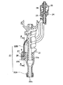
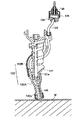
図1は本発明に係る打込機の一形態としての釘打機の破断側断面図、図2は同釘打機のプッシュレバー部分の側断面図、図3は図2のA−A線断面図、図4はプッシュレバーの射出口内で釘が傾いたときの状態を示すプッシュレバー部分の側断面図、図5は図4矢視B方向の部分断面図である。 FIG. 1 is a cutaway side sectional view of a nailing machine as an embodiment of a driving machine according to the present invention, FIG. 2 is a side sectional view of a push lever portion of the nailing machine, and FIG. 3 is a line AA in FIG. 4 is a side sectional view of the push lever portion showing a state when the nail is tilted in the injection port of the push lever, and FIG. 5 is a partial sectional view in the direction of arrow B in FIG.
先ず、図1に示す釘打機1は、側面視略横T字状の成すボディ2を備えており、このボディの上端開口部にはアッパーカバー3が気密に被着されている。又、ボディ2内には蓄圧室S1が形成されており、該ボディ2から延びるハンドル部2aの後端部には、不図示のエアホースを接続するためのエアプラグ4が設けられている。尚、当該釘打機1の不使用時には、前記エアプラグ4には図1に示すようにダストキャップ5が被着されている。
First, a
更に、ボディ2には、内部に複数本の釘6を装填することができるマガジン7が斜めに装着されるとともに、トリガ8によって上下動するプランジャ9を備えた制御バルブ10が設けられており、該制御バルブ10は、ボディ2内に形成された空気通路11と繋がっている。
Further, the
又、ボディ2内にはシリンダ12が設けられており、このシリンダ12内にはピストン13が上下摺動可能に嵌挿されている。そして、ピストン13からはドライバビット14が略垂直下方に一体に延びており、シリンダ12内はピストン13によってピストン上室S2とピストン下室S3とに区画されている。尚、シリンダ12内の底部にはピストンバンパ15が設けられている。
Further, a
更に、ボディ2とシリンダ12との間の下半部には、隔壁16によって区画された戻し空気室S4が形成されており、シリンダ12の戻し空気室S4の一部を成す部分の上下には空気孔17,18がそれぞれ周方向に複数形成されており、上方の空気孔17には、ピストン上室S2からの圧縮空気の戻し空気室S4方向への流れのみを許容する逆止弁19が備えられている。
Furthermore, a return air chamber S4 defined by a
他方、前記アッパーカバー3内には、該アッパーカバー3の天井面に対して接離するスリーブバルブ20が上下摺動可能に設けられている。即ち、このスリーブバルブ20は、シリンダ12の上端部外周とその外側に同心的に一体に形成された外筒部12aの内周に上下摺動可能に嵌合しており、シリンダ12の上端部と外筒部12aとで囲まれるリング状の空間には、スリーブバルブ20によって区画されたスリーブバルブ室S5が形成されている。そして、スリーブバルブ20は、スリーブバルブ室S5内に縮装された不図示のスプリングによって常時上方(アッパーカバー3の天井面に密着する方向)に付勢されている。
On the other hand, a
又、ボディ2の先端部には、テールカバー21と、該テールカバー21に上下方向(ピストン軸方向)に摺動可能に支持されたプッシュレバー22が設けられている。ここで、テールカバー21には、前記ドライバビット14と同軸的に垂直方向に形成された円孔状の射出口21aが形成されており、この射出口21aには前記ドライバビット14の下端部が上下に摺動可能に嵌合している。
Further, a
而して、本実施の形態では、前記プッシュレバー22は、2分割された一方の部品22Aと他方の部品22Bを回動可能に連結して構成されている。ここで、図2に詳細に示すように、一方の部品22Aは、円筒状の鋼材部品であって、これには射出口22aが前記テールカバー21に形成された射出口21aと同軸的に形成されており、その上端内周部がテールカバー21の下端部外周に傾動可能に嵌合している。
Thus, in the present embodiment, the
又、他方の部品22Bは、プレート状のプレス部品であって、鋼板を側面視略S字状にプレス成形して得られ、その上端にはロッド23を介して円柱状のアジャスタ24が連結されている。そして、このアジャスタ24は、下方が開口する円柱状のプッシュレバーガイド25に下方から上下摺動自在に嵌挿されており、該プッシュレバーガイド25との間に縮装されたスプリング26によって常時下方に付勢されている。尚、アジャスタ24とプッシュレバーガイド25は、軽量化のためにプラスチックで構成されている。
The
ここで、図2及び図3に示すように、プッシュレバー22の一方の部品22Aの上端部外周には、上方が開口する矩形ボックス状の袋状凹部22bが一体に形成されており、この袋状凹部22bに他方の部品22Bのプレート状の下端部が遊嵌されている。そして、この他方の部品22Bの下端部と一方の部品22Aに形成された袋状凹部22bとの間には、図2〜図4に示すように、前後及び左右に隙間δが形成されており、一方の部品22Aに形成された袋状凹部22bとこれに遊嵌する他方の部品22Bの下端部は、袋状凹部22bに圧入されたスプリングピン27と凸部28によって回動可能(傾動可能)に連結されるとともに、両部品22A,22Bの抜け止めがなされている。
Here, as shown in FIGS. 2 and 3, a rectangular box-shaped bag-shaped
従って、プッシュレバー22においては、一方の部品22Aが他方の部品22Bに対して360°どの方向にも回動可能(傾動可能)であって、その最大回動角(最大傾動角)は、当該プッショレバー22(部品22B)のテールカバー21に対する最大回動角(最大傾動角)よりも大きく設定されている。
Accordingly, in the
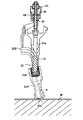
次に、以上のように構成された釘打機1の動作を図1に基づいて説明する。
Next, the operation of the nailing
図示の被打込材Wへの釘打作業に際しては、釘6をマガジン7に装填し、エアプラグ4からダストキャップ5を外した後、エアプラグ4に不図示のエアホースを繋ぐ。すると、エアコンプレッサ等の不図示の圧力供給源からエアホースを経て釘打機1のボディ2内の蓄圧室S1に圧縮空気が供給されて蓄積され、その一部は、不図示の空気通路を経て制御バルブ10内に流入し、更に空気通路11を介してスリーブバルブ室S5へ流入する。
When nailing the workpiece to be driven W shown in the figure, the
スリーブバルブ室S5へ流入した圧縮空気は、アッパーカバー3の天井面に密着しているスリーブバルブ20をアッパーカバー3の天井面に更に密着させてシリンダ12内のピストン上室S2と蓄圧室S1との連通を遮断し、蓄圧室S1内の圧縮空気のピストン上室S2への流入を防ぐため、ピストン13は静止したままの状態を保ち、釘打作業はなされない。
The compressed air that has flowed into the sleeve valve chamber S5 causes the
次に、トリッガ8の引き操作とプッシュレバー22の被打込材Wへの押し当て操作の双方がなされると、制御バルブ10内のプランジャ9が押し上げられ、スリーブバルブ室S5の圧縮空気が空気通路11を通って大気中に排出される。すると、蓄圧室S1内の圧縮空気の圧力でスリーブバルブ20が押し下げられ、シリンダ12の上部が開口すると同時にシリンダ12内のピストン上室S2と大気との連通が遮断され、蓄圧室S1の圧縮空気がシリンダ12内のピストン上室S2に流入し、ピストン13は圧縮空気の圧力で急激に下死点側に向かって下降するため、マガジン7からテールカバー21の射出口21aへと供給された釘6がドライバビット14によって打撃される。そして、ドライバビット14によって打撃された釘6は、テールカバー21の射出口21aとプッシュレバー22の一方の部品22Aに形成された射出口22aに案内されて被打込材Wに打ち込まれる。尚、ピストン13がシリンダ12内を下降して下死点に達すると、該ピストン13がピストンバンパ15に当接して該ピストンバンパ15を弾性変形させるため、このピストンバンパ15の弾性変形によって余剰エネルギーが吸収される。
Next, when both the pulling operation of the trigger 8 and the pressing operation of the
次に、トリッガ8を元に戻すか、或はプッシュレバー22を被打込材Wから離すと、プランジャ9が元に戻り、制御バルブ10内に圧縮空気が流入し、空気通路11を通ってスリーブバルブ室S5にも圧縮空気が流入し、スリーブバルブ20が押し上げられてアッパーカバー3の天井面に密着してシリンダ上室S2と蓄圧室S1との連通が遮断され、ピストン上室S2が大気に連通し、ピストン上室S2内の圧縮空気は空気通路を通って減圧及び消音されながら大気に排出される。更に、戻し空気室S4に蓄積されていた圧縮空気によってピストン13がシリンダ10内を押し上げられ、該ピストン13が急激に上死点に移動し、ピストン13及びドライバビット14は図1に示す初期状態に戻る。
Next, when the trigger 8 is returned to the original position or the
以上の工程を繰り返すことによって、マガジン7内に装填されている釘6が被打込材Wに連続的に打ち込まれていく。
By repeating the above steps, the
ところで、釘6の打込作業中にプッシュレバー22を被打込材Wに押し付けてトリガ8を引き、釘6を打ち出してコンクリート等の被打込材Wに打ち込む際、小石等に釘6が当たってしまった場合、抵抗が大きいために釘6が図4及び図5に示すように本体が大きく上方に上がるとともに、プッシュレバー22の一方の部品22Aの射出口22a内で傾き、一方の部品22Aに大きな衝撃力が作用した場合であっても、本実施の形態では、前述のようにプッシュレバー22を2つ部品22A,22Bに分割し、両部品22A,22Bをスプリングピン27と凸部28で回動可能(傾動可能)に連結したため、一方の部品22Aが他方の部品22Bに対して回動して傾き、他方の部品22Bに大きな衝撃が伝わることがない。特に、本実施の形態においては、前述のようにプッシュレバー22の一方の部品22Aが他方の部品22Bに対して360°どの方向にも回動可能(傾動可能)であって、その最大回動角(最大傾動角)が当該プッシュレバー22(部品22B)のテールカバー21に対する最大回動角(最大傾動角)よりも大きくなるようにしたため、該一方の部品22Aに作用する大きな衝撃力の他方の部品22Bやこれに連なるアジャスタ24及びプッシュレバーガイド25への伝達が確実に遮断され、これらの部品が衝撃によって変形する等の不具合が発生することがなく、それらの耐久性が高められる。
By the way, when the
尚、以上は本発明を特に空気式の釘打機に適用した形態について説明したが、本発明は、空気式以外の電動式や燃焼式の釘打機等に対しても同様に適用可能であるとともに、釘以外のピンやステープラー等の止具を打ち込むための他の任意の打込機に対しても同様に適用可能であることは勿論である。 Although the present invention has been described with respect to the embodiment in which the present invention is applied particularly to a pneumatic nailer, the present invention can be similarly applied to an electric type or combustion type nailer other than the pneumatic type. Of course, the present invention can be similarly applied to any other driving machine for driving a stopper such as a pin or a stapler other than a nail.
1 釘打機(打込機)
2 ボディ
2a ハンドル部
3 アッパーカバー
4 エアプラグ
5 ダストキャップ
6 釘(止具)
7 マガジン
8 トリガ
9 プランジャ
10 制御バルブ
11 空気通路
12 シリンダ
13 ピストン
14 ドライバビット
15 ピストンバンパ
16 隔壁
17,18 空気孔
19 逆止弁
20 スリーブバルブ
21 テールカバー
21a 射出口
22 プッシュレバー
22A 一方の部品(構材部品)
22B 他方の部品(プレス部品)
22a 射出口
22b 袋状部
23 ロッド
24 アジャスタ
25 プッシュレバーガイド
26 スプリング
27 スプリングピン
28 凸部
S1 蓄圧室
S2 ピストン上室
S3 ピストン下室
S4 戻し空気室
S5 スリーブバルブ室
W 被打込材
δ 隙間
1 Nailer (driving machine)
2
7 Magazine 8 Trigger 9
22B The other part (press part)
Claims (3)
前記プッシュレバーは一方の部品と他方の部品の少なくとも2つの部品からなり、該一方の部品と該他方の部品を回動可能に連結し、該一方の部品と該他方の部品の最大回動角を前記プッシュレバーの前記テールカバーに対する最大回動角よりも大きく設定したことを特徴とする打込機。 A piston provided with a driver bit that reciprocates by a driving source and hits a stopper, a trigger provided near the joint between the handle part and the body, and an injection port that guides the stopper hit by the driver bit A tail lever provided on the tail cover and a push lever supported on the tail cover so as to be slidable in the axial direction of the piston, and the cooperation between the pulling operation of the trigger and the pushing operation of the push lever against the driven material In the driving machine for driving the piston to drive the stopper into the driven material,
The push lever is composed of at least two parts, one part and the other part, and the one part and the other part are rotatably connected, and the maximum turning angle of the one part and the other part Is set to be larger than the maximum rotation angle of the push lever with respect to the tail cover.
Priority Applications (1)
| Application Number | Priority Date | Filing Date | Title |
|---|---|---|---|
| JP2006143269A JP4569521B2 (en) | 2006-05-23 | 2006-05-23 | Driving machine |
Applications Claiming Priority (1)
| Application Number | Priority Date | Filing Date | Title |
|---|---|---|---|
| JP2006143269A JP4569521B2 (en) | 2006-05-23 | 2006-05-23 | Driving machine |
Publications (3)
| Publication Number | Publication Date |
|---|---|
| JP2007313578A JP2007313578A (en) | 2007-12-06 |
| JP2007313578A5 JP2007313578A5 (en) | 2009-05-14 |
| JP4569521B2 true JP4569521B2 (en) | 2010-10-27 |
Family
ID=38847902
Family Applications (1)
| Application Number | Title | Priority Date | Filing Date |
|---|---|---|---|
| JP2006143269A Expired - Fee Related JP4569521B2 (en) | 2006-05-23 | 2006-05-23 | Driving machine |
Country Status (1)
| Country | Link |
|---|---|
| JP (1) | JP4569521B2 (en) |
Families Citing this family (1)
| Publication number | Priority date | Publication date | Assignee | Title |
|---|---|---|---|---|
| JP6604068B2 (en) * | 2015-07-21 | 2019-11-13 | マックス株式会社 | Driving tool |
Citations (5)
| Publication number | Priority date | Publication date | Assignee | Title |
|---|---|---|---|---|
| JPH03120989U (en) * | 1990-03-19 | 1991-12-11 | ||
| JPH0588880U (en) * | 1992-05-15 | 1993-12-03 | 日立工機株式会社 | Driving machine safety device |
| JP2000263468A (en) * | 1999-03-19 | 2000-09-26 | Hitachi Koki Co Ltd | Driving machine |
| JP2004050376A (en) * | 2002-07-23 | 2004-02-19 | Max Co Ltd | Mechanism for connecting contact member of nailing machine |
| JP2005161496A (en) * | 2003-12-04 | 2005-06-23 | Max Co Ltd | Contact nose connecting mechanism of nailing machine |
-
2006
- 2006-05-23 JP JP2006143269A patent/JP4569521B2/en not_active Expired - Fee Related
Patent Citations (5)
| Publication number | Priority date | Publication date | Assignee | Title |
|---|---|---|---|---|
| JPH03120989U (en) * | 1990-03-19 | 1991-12-11 | ||
| JPH0588880U (en) * | 1992-05-15 | 1993-12-03 | 日立工機株式会社 | Driving machine safety device |
| JP2000263468A (en) * | 1999-03-19 | 2000-09-26 | Hitachi Koki Co Ltd | Driving machine |
| JP2004050376A (en) * | 2002-07-23 | 2004-02-19 | Max Co Ltd | Mechanism for connecting contact member of nailing machine |
| JP2005161496A (en) * | 2003-12-04 | 2005-06-23 | Max Co Ltd | Contact nose connecting mechanism of nailing machine |
Also Published As
| Publication number | Publication date |
|---|---|
| JP2007313578A (en) | 2007-12-06 |
Similar Documents
| Publication | Publication Date | Title |
|---|---|---|
| JP4720656B2 (en) | Driving machine | |
| JP5509770B2 (en) | Air driving machine | |
| JP5082051B2 (en) | AIR HAMMER TOOL, AND METHOD OF ADJUSTING BATTLE FORCE OF THE AIR HAMMER TOOL | |
| JP4687572B2 (en) | Driving machine | |
| EP2199026B1 (en) | Cellular foam bumper for nailer | |
| JP4752751B2 (en) | Driving machine | |
| JP4761257B2 (en) | Fastener driving machine | |
| JP5716395B2 (en) | Driving machine | |
| JP5748104B2 (en) | Driving machine | |
| JP4569521B2 (en) | Driving machine | |
| JP4877464B2 (en) | Offset structure in contact of driving tool | |
| JP5354839B2 (en) | Floor nailing machine | |
| JP5071287B2 (en) | Pneumatic tool | |
| JP2017119330A (en) | Driving machine | |
| JP5320583B2 (en) | Driving tool | |
| JP2010023174A (en) | Driving machine for staples | |
| JP4569520B2 (en) | Driving machine | |
| JP7073197B2 (en) | Driving tool | |
| JP5257588B2 (en) | Driving machine | |
| JP2006026786A (en) | Driving machine | |
| WO2023080192A1 (en) | Work machine | |
| JP4941001B2 (en) | Staple driving driver | |
| JP4400269B2 (en) | Driving machine | |
| JPS5938999Y2 (en) | Holding device for impact driver in impact tool | |
| JP2019107723A (en) | Driving machine |
Legal Events
| Date | Code | Title | Description |
|---|---|---|---|
| RD05 | Notification of revocation of power of attorney |
Free format text: JAPANESE INTERMEDIATE CODE: A7425 Effective date: 20090126 |
|
| A521 | Written amendment |
Free format text: JAPANESE INTERMEDIATE CODE: A523 Effective date: 20090331 |
|
| A621 | Written request for application examination |
Free format text: JAPANESE INTERMEDIATE CODE: A621 Effective date: 20090331 |
|
| A977 | Report on retrieval |
Free format text: JAPANESE INTERMEDIATE CODE: A971007 Effective date: 20100708 |
|
| TRDD | Decision of grant or rejection written | ||
| A01 | Written decision to grant a patent or to grant a registration (utility model) |
Free format text: JAPANESE INTERMEDIATE CODE: A01 Effective date: 20100713 |
|
| A01 | Written decision to grant a patent or to grant a registration (utility model) |
Free format text: JAPANESE INTERMEDIATE CODE: A01 |
|
| A61 | First payment of annual fees (during grant procedure) |
Free format text: JAPANESE INTERMEDIATE CODE: A61 Effective date: 20100726 |
|
| FPAY | Renewal fee payment (event date is renewal date of database) |
Free format text: PAYMENT UNTIL: 20130820 Year of fee payment: 3 |
|
| R150 | Certificate of patent or registration of utility model |
Free format text: JAPANESE INTERMEDIATE CODE: R150 |
|
| FPAY | Renewal fee payment (event date is renewal date of database) |
Free format text: PAYMENT UNTIL: 20140820 Year of fee payment: 4 |
|
| LAPS | Cancellation because of no payment of annual fees |