JP4568761B2 - Method and apparatus for sealing - Google Patents
Method and apparatus for sealing Download PDFInfo
- Publication number
- JP4568761B2 JP4568761B2 JP2007546606A JP2007546606A JP4568761B2 JP 4568761 B2 JP4568761 B2 JP 4568761B2 JP 2007546606 A JP2007546606 A JP 2007546606A JP 2007546606 A JP2007546606 A JP 2007546606A JP 4568761 B2 JP4568761 B2 JP 4568761B2
- Authority
- JP
- Japan
- Prior art keywords
- sealing
- magnetic field
- laminate
- anvil
- packaging material
- Prior art date
- Legal status (The legal status is an assumption and is not a legal conclusion. Google has not performed a legal analysis and makes no representation as to the accuracy of the status listed.)
- Expired - Fee Related
Links
Images


Classifications
-
- B—PERFORMING OPERATIONS; TRANSPORTING
- B29—WORKING OF PLASTICS; WORKING OF SUBSTANCES IN A PLASTIC STATE IN GENERAL
- B29C—SHAPING OR JOINING OF PLASTICS; SHAPING OF MATERIAL IN A PLASTIC STATE, NOT OTHERWISE PROVIDED FOR; AFTER-TREATMENT OF THE SHAPED PRODUCTS, e.g. REPAIRING
- B29C65/00—Joining or sealing of preformed parts, e.g. welding of plastics materials; Apparatus therefor
- B29C65/02—Joining or sealing of preformed parts, e.g. welding of plastics materials; Apparatus therefor by heating, with or without pressure
- B29C65/34—Joining or sealing of preformed parts, e.g. welding of plastics materials; Apparatus therefor by heating, with or without pressure using heated elements which remain in the joint, e.g. "verlorenes Schweisselement"
- B29C65/36—Joining or sealing of preformed parts, e.g. welding of plastics materials; Apparatus therefor by heating, with or without pressure using heated elements which remain in the joint, e.g. "verlorenes Schweisselement" heated by induction
- B29C65/3604—Joining or sealing of preformed parts, e.g. welding of plastics materials; Apparatus therefor by heating, with or without pressure using heated elements which remain in the joint, e.g. "verlorenes Schweisselement" heated by induction characterised by the type of elements heated by induction which remain in the joint
- B29C65/3608—Joining or sealing of preformed parts, e.g. welding of plastics materials; Apparatus therefor by heating, with or without pressure using heated elements which remain in the joint, e.g. "verlorenes Schweisselement" heated by induction characterised by the type of elements heated by induction which remain in the joint comprising single particles, e.g. fillers or discontinuous fibre-reinforcements
- B29C65/3612—Joining or sealing of preformed parts, e.g. welding of plastics materials; Apparatus therefor by heating, with or without pressure using heated elements which remain in the joint, e.g. "verlorenes Schweisselement" heated by induction characterised by the type of elements heated by induction which remain in the joint comprising single particles, e.g. fillers or discontinuous fibre-reinforcements comprising fillers
-
- B—PERFORMING OPERATIONS; TRANSPORTING
- B29—WORKING OF PLASTICS; WORKING OF SUBSTANCES IN A PLASTIC STATE IN GENERAL
- B29C—SHAPING OR JOINING OF PLASTICS; SHAPING OF MATERIAL IN A PLASTIC STATE, NOT OTHERWISE PROVIDED FOR; AFTER-TREATMENT OF THE SHAPED PRODUCTS, e.g. REPAIRING
- B29C66/00—General aspects of processes or apparatus for joining preformed parts
- B29C66/01—General aspects dealing with the joint area or with the area to be joined
- B29C66/05—Particular design of joint configurations
- B29C66/10—Particular design of joint configurations particular design of the joint cross-sections
- B29C66/11—Joint cross-sections comprising a single joint-segment, i.e. one of the parts to be joined comprising a single joint-segment in the joint cross-section
- B29C66/112—Single lapped joints
- B29C66/1122—Single lap to lap joints, i.e. overlap joints
-
- B—PERFORMING OPERATIONS; TRANSPORTING
- B29—WORKING OF PLASTICS; WORKING OF SUBSTANCES IN A PLASTIC STATE IN GENERAL
- B29C—SHAPING OR JOINING OF PLASTICS; SHAPING OF MATERIAL IN A PLASTIC STATE, NOT OTHERWISE PROVIDED FOR; AFTER-TREATMENT OF THE SHAPED PRODUCTS, e.g. REPAIRING
- B29C66/00—General aspects of processes or apparatus for joining preformed parts
- B29C66/40—General aspects of joining substantially flat articles, e.g. plates, sheets or web-like materials; Making flat seams in tubular or hollow articles; Joining single elements to substantially flat surfaces
- B29C66/41—Joining substantially flat articles ; Making flat seams in tubular or hollow articles
- B29C66/43—Joining a relatively small portion of the surface of said articles
- B29C66/432—Joining a relatively small portion of the surface of said articles for making tubular articles or closed loops, e.g. by joining several sheets ; for making hollow articles or hollow preforms
- B29C66/4322—Joining a relatively small portion of the surface of said articles for making tubular articles or closed loops, e.g. by joining several sheets ; for making hollow articles or hollow preforms by joining a single sheet to itself
-
- B—PERFORMING OPERATIONS; TRANSPORTING
- B29—WORKING OF PLASTICS; WORKING OF SUBSTANCES IN A PLASTIC STATE IN GENERAL
- B29C—SHAPING OR JOINING OF PLASTICS; SHAPING OF MATERIAL IN A PLASTIC STATE, NOT OTHERWISE PROVIDED FOR; AFTER-TREATMENT OF THE SHAPED PRODUCTS, e.g. REPAIRING
- B29C66/00—General aspects of processes or apparatus for joining preformed parts
- B29C66/40—General aspects of joining substantially flat articles, e.g. plates, sheets or web-like materials; Making flat seams in tubular or hollow articles; Joining single elements to substantially flat surfaces
- B29C66/49—Internally supporting the, e.g. tubular, article during joining
-
- B—PERFORMING OPERATIONS; TRANSPORTING
- B29—WORKING OF PLASTICS; WORKING OF SUBSTANCES IN A PLASTIC STATE IN GENERAL
- B29C—SHAPING OR JOINING OF PLASTICS; SHAPING OF MATERIAL IN A PLASTIC STATE, NOT OTHERWISE PROVIDED FOR; AFTER-TREATMENT OF THE SHAPED PRODUCTS, e.g. REPAIRING
- B29C66/00—General aspects of processes or apparatus for joining preformed parts
- B29C66/70—General aspects of processes or apparatus for joining preformed parts characterised by the composition, physical properties or the structure of the material of the parts to be joined; Joining with non-plastics material
- B29C66/72—General aspects of processes or apparatus for joining preformed parts characterised by the composition, physical properties or the structure of the material of the parts to be joined; Joining with non-plastics material characterised by the structure of the material of the parts to be joined
- B29C66/723—General aspects of processes or apparatus for joining preformed parts characterised by the composition, physical properties or the structure of the material of the parts to be joined; Joining with non-plastics material characterised by the structure of the material of the parts to be joined being multi-layered
-
- B—PERFORMING OPERATIONS; TRANSPORTING
- B29—WORKING OF PLASTICS; WORKING OF SUBSTANCES IN A PLASTIC STATE IN GENERAL
- B29C—SHAPING OR JOINING OF PLASTICS; SHAPING OF MATERIAL IN A PLASTIC STATE, NOT OTHERWISE PROVIDED FOR; AFTER-TREATMENT OF THE SHAPED PRODUCTS, e.g. REPAIRING
- B29C66/00—General aspects of processes or apparatus for joining preformed parts
- B29C66/80—General aspects of machine operations or constructions and parts thereof
-
- B—PERFORMING OPERATIONS; TRANSPORTING
- B29—WORKING OF PLASTICS; WORKING OF SUBSTANCES IN A PLASTIC STATE IN GENERAL
- B29C—SHAPING OR JOINING OF PLASTICS; SHAPING OF MATERIAL IN A PLASTIC STATE, NOT OTHERWISE PROVIDED FOR; AFTER-TREATMENT OF THE SHAPED PRODUCTS, e.g. REPAIRING
- B29C53/00—Shaping by bending, folding, twisting, straightening or flattening; Apparatus therefor
- B29C53/36—Bending and joining, e.g. for making hollow articles
- B29C53/38—Bending and joining, e.g. for making hollow articles by bending sheets or strips at right angles to the longitudinal axis of the article being formed and joining the edges
-
- B—PERFORMING OPERATIONS; TRANSPORTING
- B29—WORKING OF PLASTICS; WORKING OF SUBSTANCES IN A PLASTIC STATE IN GENERAL
- B29C—SHAPING OR JOINING OF PLASTICS; SHAPING OF MATERIAL IN A PLASTIC STATE, NOT OTHERWISE PROVIDED FOR; AFTER-TREATMENT OF THE SHAPED PRODUCTS, e.g. REPAIRING
- B29C65/00—Joining or sealing of preformed parts, e.g. welding of plastics materials; Apparatus therefor
- B29C65/02—Joining or sealing of preformed parts, e.g. welding of plastics materials; Apparatus therefor by heating, with or without pressure
- B29C65/34—Joining or sealing of preformed parts, e.g. welding of plastics materials; Apparatus therefor by heating, with or without pressure using heated elements which remain in the joint, e.g. "verlorenes Schweisselement"
- B29C65/36—Joining or sealing of preformed parts, e.g. welding of plastics materials; Apparatus therefor by heating, with or without pressure using heated elements which remain in the joint, e.g. "verlorenes Schweisselement" heated by induction
- B29C65/3668—Joining or sealing of preformed parts, e.g. welding of plastics materials; Apparatus therefor by heating, with or without pressure using heated elements which remain in the joint, e.g. "verlorenes Schweisselement" heated by induction characterised by the means for supplying heat to said heated elements which remain in the join, e.g. special induction coils
-
- B—PERFORMING OPERATIONS; TRANSPORTING
- B29—WORKING OF PLASTICS; WORKING OF SUBSTANCES IN A PLASTIC STATE IN GENERAL
- B29C—SHAPING OR JOINING OF PLASTICS; SHAPING OF MATERIAL IN A PLASTIC STATE, NOT OTHERWISE PROVIDED FOR; AFTER-TREATMENT OF THE SHAPED PRODUCTS, e.g. REPAIRING
- B29C66/00—General aspects of processes or apparatus for joining preformed parts
- B29C66/70—General aspects of processes or apparatus for joining preformed parts characterised by the composition, physical properties or the structure of the material of the parts to be joined; Joining with non-plastics material
- B29C66/72—General aspects of processes or apparatus for joining preformed parts characterised by the composition, physical properties or the structure of the material of the parts to be joined; Joining with non-plastics material characterised by the structure of the material of the parts to be joined
- B29C66/723—General aspects of processes or apparatus for joining preformed parts characterised by the composition, physical properties or the structure of the material of the parts to be joined; Joining with non-plastics material characterised by the structure of the material of the parts to be joined being multi-layered
- B29C66/7232—General aspects of processes or apparatus for joining preformed parts characterised by the composition, physical properties or the structure of the material of the parts to be joined; Joining with non-plastics material characterised by the structure of the material of the parts to be joined being multi-layered comprising a non-plastics layer
- B29C66/72321—General aspects of processes or apparatus for joining preformed parts characterised by the composition, physical properties or the structure of the material of the parts to be joined; Joining with non-plastics material characterised by the structure of the material of the parts to be joined being multi-layered comprising a non-plastics layer consisting of metals or their alloys
-
- B—PERFORMING OPERATIONS; TRANSPORTING
- B29—WORKING OF PLASTICS; WORKING OF SUBSTANCES IN A PLASTIC STATE IN GENERAL
- B29C—SHAPING OR JOINING OF PLASTICS; SHAPING OF MATERIAL IN A PLASTIC STATE, NOT OTHERWISE PROVIDED FOR; AFTER-TREATMENT OF THE SHAPED PRODUCTS, e.g. REPAIRING
- B29C66/00—General aspects of processes or apparatus for joining preformed parts
- B29C66/80—General aspects of machine operations or constructions and parts thereof
- B29C66/81—General aspects of the pressing elements, i.e. the elements applying pressure on the parts to be joined in the area to be joined, e.g. the welding jaws or clamps
- B29C66/812—General aspects of the pressing elements, i.e. the elements applying pressure on the parts to be joined in the area to be joined, e.g. the welding jaws or clamps characterised by the composition, by the structure, by the intensive physical properties or by the optical properties of the material constituting the pressing elements, e.g. constituting the welding jaws or clamps
- B29C66/8122—General aspects of the pressing elements, i.e. the elements applying pressure on the parts to be joined in the area to be joined, e.g. the welding jaws or clamps characterised by the composition, by the structure, by the intensive physical properties or by the optical properties of the material constituting the pressing elements, e.g. constituting the welding jaws or clamps characterised by the composition of the material constituting the pressing elements, e.g. constituting the welding jaws or clamps
-
- B—PERFORMING OPERATIONS; TRANSPORTING
- B29—WORKING OF PLASTICS; WORKING OF SUBSTANCES IN A PLASTIC STATE IN GENERAL
- B29C—SHAPING OR JOINING OF PLASTICS; SHAPING OF MATERIAL IN A PLASTIC STATE, NOT OTHERWISE PROVIDED FOR; AFTER-TREATMENT OF THE SHAPED PRODUCTS, e.g. REPAIRING
- B29C66/00—General aspects of processes or apparatus for joining preformed parts
- B29C66/80—General aspects of machine operations or constructions and parts thereof
- B29C66/81—General aspects of the pressing elements, i.e. the elements applying pressure on the parts to be joined in the area to be joined, e.g. the welding jaws or clamps
- B29C66/812—General aspects of the pressing elements, i.e. the elements applying pressure on the parts to be joined in the area to be joined, e.g. the welding jaws or clamps characterised by the composition, by the structure, by the intensive physical properties or by the optical properties of the material constituting the pressing elements, e.g. constituting the welding jaws or clamps
- B29C66/8126—General aspects of the pressing elements, i.e. the elements applying pressure on the parts to be joined in the area to be joined, e.g. the welding jaws or clamps characterised by the composition, by the structure, by the intensive physical properties or by the optical properties of the material constituting the pressing elements, e.g. constituting the welding jaws or clamps characterised by the intensive physical properties or by the optical properties of the material constituting the pressing elements, e.g. constituting the welding jaws or clamps
- B29C66/81262—Electrical and dielectric properties, e.g. electrical conductivity
-
- B—PERFORMING OPERATIONS; TRANSPORTING
- B29—WORKING OF PLASTICS; WORKING OF SUBSTANCES IN A PLASTIC STATE IN GENERAL
- B29C—SHAPING OR JOINING OF PLASTICS; SHAPING OF MATERIAL IN A PLASTIC STATE, NOT OTHERWISE PROVIDED FOR; AFTER-TREATMENT OF THE SHAPED PRODUCTS, e.g. REPAIRING
- B29C66/00—General aspects of processes or apparatus for joining preformed parts
- B29C66/80—General aspects of machine operations or constructions and parts thereof
- B29C66/81—General aspects of the pressing elements, i.e. the elements applying pressure on the parts to be joined in the area to be joined, e.g. the welding jaws or clamps
- B29C66/818—General aspects of the pressing elements, i.e. the elements applying pressure on the parts to be joined in the area to be joined, e.g. the welding jaws or clamps characterised by the cooling constructional aspects, or by the thermal or electrical insulating or conducting constructional aspects of the welding jaws or of the clamps ; comprising means for compensating for the thermal expansion of the welding jaws or of the clamps
- B29C66/8187—General aspects of the pressing elements, i.e. the elements applying pressure on the parts to be joined in the area to be joined, e.g. the welding jaws or clamps characterised by the cooling constructional aspects, or by the thermal or electrical insulating or conducting constructional aspects of the welding jaws or of the clamps ; comprising means for compensating for the thermal expansion of the welding jaws or of the clamps characterised by the electrical insulating constructional aspects
- B29C66/81871—General aspects of the pressing elements, i.e. the elements applying pressure on the parts to be joined in the area to be joined, e.g. the welding jaws or clamps characterised by the cooling constructional aspects, or by the thermal or electrical insulating or conducting constructional aspects of the welding jaws or of the clamps ; comprising means for compensating for the thermal expansion of the welding jaws or of the clamps characterised by the electrical insulating constructional aspects of the welding jaws
-
- B—PERFORMING OPERATIONS; TRANSPORTING
- B29—WORKING OF PLASTICS; WORKING OF SUBSTANCES IN A PLASTIC STATE IN GENERAL
- B29C—SHAPING OR JOINING OF PLASTICS; SHAPING OF MATERIAL IN A PLASTIC STATE, NOT OTHERWISE PROVIDED FOR; AFTER-TREATMENT OF THE SHAPED PRODUCTS, e.g. REPAIRING
- B29C66/00—General aspects of processes or apparatus for joining preformed parts
- B29C66/80—General aspects of machine operations or constructions and parts thereof
- B29C66/83—General aspects of machine operations or constructions and parts thereof characterised by the movement of the joining or pressing tools
- B29C66/832—Reciprocating joining or pressing tools
- B29C66/8322—Joining or pressing tools reciprocating along one axis
-
- B—PERFORMING OPERATIONS; TRANSPORTING
- B29—WORKING OF PLASTICS; WORKING OF SUBSTANCES IN A PLASTIC STATE IN GENERAL
- B29K—INDEXING SCHEME ASSOCIATED WITH SUBCLASSES B29B, B29C OR B29D, RELATING TO MOULDING MATERIALS OR TO MATERIALS FOR MOULDS, REINFORCEMENTS, FILLERS OR PREFORMED PARTS, e.g. INSERTS
- B29K2995/00—Properties of moulding materials, reinforcements, fillers, preformed parts or moulds
- B29K2995/0003—Properties of moulding materials, reinforcements, fillers, preformed parts or moulds having particular electrical or magnetic properties, e.g. piezoelectric
- B29K2995/0008—Magnetic or paramagnetic
-
- B—PERFORMING OPERATIONS; TRANSPORTING
- B29—WORKING OF PLASTICS; WORKING OF SUBSTANCES IN A PLASTIC STATE IN GENERAL
- B29L—INDEXING SCHEME ASSOCIATED WITH SUBCLASS B29C, RELATING TO PARTICULAR ARTICLES
- B29L2009/00—Layered products
-
- B—PERFORMING OPERATIONS; TRANSPORTING
- B29—WORKING OF PLASTICS; WORKING OF SUBSTANCES IN A PLASTIC STATE IN GENERAL
- B29L—INDEXING SCHEME ASSOCIATED WITH SUBCLASS B29C, RELATING TO PARTICULAR ARTICLES
- B29L2031/00—Other particular articles
- B29L2031/712—Containers; Packaging elements or accessories, Packages
Description
本発明は、磁化可能な粒子を含む少なくとも1つの層を含む包装材料積層品の磁気ヒステリシス封止のための方法及び装置に関する。 The present invention relates to a method and apparatus for magnetic hysteresis sealing of packaging material laminates comprising at least one layer comprising magnetizable particles.
参照により本明細書に組み込む国際特許出願公開WO03/095198には、磁化可能な粒子を含む少なくとも1つの層を含む包装材料積層品が記載されている。この積層品は、たとえば液体食品パッケージを製造するために使用されるタイプのものであり、概して、紙又は厚紙(carton)の層、プラスチック及びバリアの諸層、たとえば酸素バリアなどを備える。外層の1つは、通常、熱可塑性材料の封止可能な層であり、ある積層品を別の積層品に対して封止するとき使用される。熱可塑性の層の使用は、当技術分野で周知であり、本明細書ではこれ以上述べない。 International Patent Application Publication No. WO 03/095198, which is incorporated herein by reference, describes a packaging material laminate comprising at least one layer comprising magnetizable particles. The laminate is of the type used, for example, to produce liquid food packages and generally comprises a paper or carton layer, plastic and barrier layers, such as an oxygen barrier. One of the outer layers is usually a sealable layer of thermoplastic material and is used when sealing one laminate to another laminate. The use of thermoplastic layers is well known in the art and will not be discussed further herein.
磁化可能な粒子は、たとえばマグネタイトFe3O4とすることができ、約0.5μmの平均サイズを有する可能性がある。当然ながら、他の材料及び粒子サイズもまた使用することができる。たとえばマグヘマイトFe2O3など他の材料、並びに他の(より大きい、またより小さい)粒子サイズが存在する。一部のものは、より高いシール加熱力(seal heating power)を提供する可能性がある。しかし、粒子を選択するときには注意すべきである。粒子の中には、法律により食品包装で使用することができないものもあれば、それらを製造することにより、より高いコストを必要とするものもある。現在、0.5μmより小さい粒子は、コストのかかる化学製造プロセスを必要とし、一方、より大きな粒子は、ふるいにかけること(sifting)によって機械的に製造することができる。 The magnetizable particles can be, for example, magnetite Fe 3 O 4 and can have an average size of about 0.5 μm. Of course, other materials and particle sizes can also be used. There are other materials such as maghemite Fe 2 O 3 as well as other (larger and smaller) particle sizes. Some may provide higher seal heating power. However, care should be taken when selecting the particles. Some particles cannot be used in food packaging by law, while others require higher costs by producing them. Currently, particles smaller than 0.5 μm require costly chemical manufacturing processes, while larger particles can be mechanically produced by sifting.
磁化可能な粒子は、包装材料積層品の任意の層内で、好ましくはプラスチック層の1つで分散される。別法として、スウェーデン特許出願第0501409−7号及び第0501408−9号に記載されているように、印刷用インク又はホットメルト内で付着させることができ、印刷用インク又はホットメルトは、たとえば封止ゾーン(sealing zone)内で包装材料に付着される。 The magnetizable particles are dispersed in any layer of the packaging material laminate, preferably in one of the plastic layers. Alternatively, it can be applied in a printing ink or hot melt as described in Swedish patent applications 0501409-7 and 0501408-9, the printing ink or hot melt being sealed, for example, It is attached to the packaging material in a sealing zone.
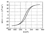
磁化可能な粒子を含む包装材料積層品は、磁気ヒステリシス損失によって生成される熱を使用して別の包装材料積層品に対して封止することができる。第1及び第2の積層品の封止ゾーン付近で交流磁界を印加することにより、磁気材料が、図1aにおけるヒステリシスループ(hysteresis loop)に従って磁化されることになる。縦軸は、材料内での磁気モーメントBを表し、横軸は、印加された磁界Hを表す。ループによって囲まれた領域(area)は、磁化可能な粒子により材料内で生成されるエネルギーを表す。これは、積層品の外側の封止可能な層を溶融し、それによってシールを作り出すために使用されることになるエネルギーであるため、ヒステリシスループ領域を最大化することにより、封止プロセスが最適化されることが理解される。 A packaging material laminate comprising magnetizable particles can be sealed against another packaging material laminate using heat generated by magnetic hysteresis losses. By applying an alternating magnetic field in the vicinity of the sealing zone of the first and second laminates, the magnetic material will be magnetized according to the hysteresis loop in FIG. 1a. The vertical axis represents the magnetic moment B in the material, and the horizontal axis represents the applied magnetic field H. The area enclosed by the loop represents the energy generated in the material by the magnetizable particles. Since this is the energy that will be used to melt the sealable layer outside the laminate and thereby create a seal, the sealing process is optimized by maximizing the hysteresis loop area It is understood that
一般に、エネルギーと封止時間は、封止プロセスを制御するための2つのパラメータである。封止エネルギーが減少される場合、封止時間を増大しなければならず、逆も同様である。同じことが、磁気ヒステリシス封止にも当てはまる。ヒステリシスループ領域を大きくすることができるほど、(積層品内の粒子の量が同じであるならば)必要とされる封止時間が短くなる。高速包装機械では、封止時間がきわめて重要である。したがって、磁気ヒステリシス封止を、たとえば誘導封止(induction sealing)又は超音波封止など他の封止技法に対する可能な代替として考慮しなければならない場合、必要とされる封止時間は、他の技法によって必要とされる時間を超えるべきでない。 In general, energy and sealing time are two parameters for controlling the sealing process. If the sealing energy is reduced, the sealing time must be increased and vice versa. The same applies to magnetic hysteresis sealing. The larger the hysteresis loop area, the shorter the required sealing time (if the amount of particles in the laminate is the same). In high speed packaging machines, sealing time is extremely important. Thus, if magnetic hysteresis sealing must be considered as a possible alternative to other sealing techniques such as induction sealing or ultrasonic sealing, the required sealing time is The time required by the technique should not be exceeded.
ヒステリシスエネルギー生成は、実質的に2つのやり方で制御することができる。 Hysteresis energy generation can be controlled in substantially two ways.
1つのやり方は、ヒステリシスループ領域を増大させることである。これは、積層品の粒子内であるレベルの磁気飽和に達するまで、印加される磁界Hを増大させることによって達成することができる。磁気飽和レベルSが図1bに示されている。しかし、飽和レベルSを超えて磁界Hを増大させても、ヒステリシスループ領域が延長されないことになる。 One way is to increase the hysteresis loop area. This can be achieved by increasing the applied magnetic field H until a certain level of magnetic saturation is reached in the particles of the laminate. The magnetic saturation level S is shown in FIG. However, even if the magnetic field H is increased beyond the saturation level S, the hysteresis loop region is not extended.
もう1つのやり方は、印加される交流磁界の周波数を増大させることである。各サイクルで、ヒステリシスループ領域に対応するエネルギー生成が生じ、単位時間当たりサイクル数を増大させることにより、生成されるエネルギーの総量が増大される。したがって、一例として、1Hzでは、1秒当たり1ループ領域のエネルギー貢献が得られ、一方、2Hzでは、1秒当たり2倍のエネルギー貢献が得られることになる。 Another way is to increase the frequency of the applied alternating magnetic field. Each cycle results in energy generation corresponding to the hysteresis loop region, and increasing the number of cycles per unit time increases the total amount of energy generated. Thus, as an example, at 1 Hz, an energy contribution of 1 loop region per second is obtained, whereas at 2 Hz, an energy contribution of 2 times per second is obtained.
この状況では、放出することができる、またその周波数帯域が公共使用に開かれている電磁放射の量を当局が規制していることについて述べるべきである。いくつかの周波数帯域間隔では、その使用が制限される。欧州では、これは現在、EMC指令によって管理される。 In this situation it should be mentioned that the authorities regulate the amount of electromagnetic radiation that can be emitted and whose frequency band is open to public use. In some frequency band intervals, its use is limited. In Europe, this is currently managed by the EMC directive.
上述のように、放出することができる放射の量に対して規制がある。許容値を超える場合、その装置又は機械は、周囲の環境から遮蔽することを必要とする。そのような遮蔽は、一般に、高周波が使用される装置又は機械を機械的にカプセル化することによって行われる。しかし、高周波装置からの放出は、その遮蔽内のどのような小さな開口を介しても離脱する可能性がより高いため、遮蔽するのがより困難であることが知られている。したがって、実際上の、また経済上の理由で、低い周波数を使用することが好ましい。現在、0.5MHzと5MHzの間の間隔が好ましい。したがって、周波数を増大させることを強いられないようにヒステリシスループ領域を最適化することが可能であることが重要である。 As mentioned above, there are restrictions on the amount of radiation that can be emitted. If the tolerance is exceeded, the device or machine needs to be shielded from the surrounding environment. Such shielding is typically done by mechanically encapsulating a device or machine in which high frequencies are used. However, emissions from high frequency devices are known to be more difficult to shield because they are more likely to detach through any small opening in the shield. Therefore, it is preferable to use a lower frequency for practical and economic reasons. Currently, an interval between 0.5 MHz and 5 MHz is preferred. Therefore, it is important to be able to optimize the hysteresis loop region so that it is not forced to increase the frequency.
本発明の一目的は、高速包装機械において、包装材料積層品を封止するために磁気ヒステリシスを使用する効率的且つ実際的なやり方を見出すことであった。他の目的は、包装材料積層品の過熱が防止される封止技法を達成することである。 One object of the present invention was to find an efficient and practical way to use magnetic hysteresis to seal packaging material laminates in high speed packaging machines. Another object is to achieve a sealing technique in which overheating of the packaging material laminate is prevented.
これらの目的は、封止ゾーン内で積層品に交流磁界を与え、それによって、磁気ヒステリシス損失を、磁化可能な粒子を含む積層品内で生成し、その損失が、封止ゾーン内で封止可能な層を実質的に溶融する熱を生み出すこと、及び、封止圧力を第1及び第2の積層品に加え、その圧力により、第1と第2の積層品が封止ゾーン内で互いに押圧され、それによって積層品を互いに封止することを含む方法によって達成されている。 These objectives provide an alternating magnetic field to the laminate within the sealing zone, thereby generating a magnetic hysteresis loss in the laminate containing magnetizable particles, and that loss is sealed within the sealing zone. Creating heat that substantially melts the possible layers, and applying a sealing pressure to the first and second laminates, which causes the first and second laminates to move together in the sealing zone. This is achieved by a method comprising pressing and thereby sealing the laminates together.
磁化可能な粒子を含む包装材料積層品に磁界を印加することは効果的であり、包装機械で通常使用される技法に比べて、同等に良好な封止技法であることが判明している。さらに、磁気ヒステリシス封止の使用により、包装材料積層品の過熱が防止される。これは、積層品が加熱されたとき、磁化可能な粒子の強磁性が徐々に途絶え始めることによる。したがって、温度上昇中には、ヒステリシスループ領域が減少することになる。したがって、材料内で生成されるエネルギーもまた減少することになる。そのようなエネルギー減少により、材料内で生成される熱もまた、減少することになる。したがって、熱が減少しつつあるため、粒子の磁化は、再び増大することが可能になり、材料内で生成される熱によって再び減少し始めるまで増大することが可能になる。したがって、温度が、ある範囲内で変動するが決してそれを超えないシステムが形成されている。磁化可能な粒子、粒子量、及び包装材料積層品の構造を適切に選択することにより、過熱の危険性が解消される。 It has been found that applying a magnetic field to a packaging material laminate comprising magnetizable particles is effective and is an equally good sealing technique compared to the techniques normally used in packaging machines. Furthermore, the use of magnetic hysteresis sealing prevents overheating of the packaging material laminate. This is due to the fact that the ferromagnetism of the magnetizable particles gradually begins to cease when the laminate is heated. Therefore, the hysteresis loop region decreases during the temperature rise. Thus, the energy generated in the material will also be reduced. Such energy reduction will also reduce the heat generated in the material. Thus, as the heat is decreasing, the magnetization of the particles can increase again and can increase until it begins to decrease again due to the heat generated in the material. Thus, a system is formed in which the temperature varies within a range but never exceeds it. By properly selecting the magnetizable particles, the amount of particles, and the structure of the packaging material laminate, the risk of overheating is eliminated.
現在の好ましい実施形態では、本方法は、磁力線の主方向が、第1の包装材料積層品を構成する平面と実質的に平行となるように、交流磁界を与えるステップを含む。このようにして、磁界が封止ゾーン内で生成され、その磁界は、高速包装機械において、業界で受け入れられる封止時間及び周波数を達成するのに十分である。磁力線の主方向が積層品平面と実質的に平行であるヒステリシスループの領域が、磁力線の主方向が積層品平面に対して実質的に垂直であるヒステリシスループの領域に実質的に等しいことが判明している。その違いは、垂直の場合における領域を得るために必要とされる磁界の方が高く、実際、ほぼ2倍である。したがって、平行の場合の方が効率的であるように思われる。 In a presently preferred embodiment, the method includes applying an alternating magnetic field such that the main direction of the magnetic field lines is substantially parallel to the plane comprising the first packaging material laminate. In this way, a magnetic field is generated in the sealing zone that is sufficient to achieve industry accepted sealing times and frequencies in high speed packaging machines. It turns out that the area of the hysteresis loop where the main direction of the magnetic field lines is substantially parallel to the laminate plane is substantially equal to the area of the hysteresis loop where the main direction of the magnetic field lines is substantially perpendicular to the laminate plane is doing. The difference is that the magnetic field required to obtain the region in the vertical case is higher, in fact almost twice. Therefore, the parallel case seems to be more efficient.
他の現在の好ましい実施形態では、本方法は、磁化可能な粒子を実質的に磁気飽和レベルに到達させるのに十分な、実質的に大きな強度の交流磁界を生成するステップを含む。上述のように、ヒステリシスループ領域を大きくすることができるほど、より多くのエネルギーが材料内で生成される。その領域は材料の磁気飽和レベルまで増大しつつあるため、材料をそのレベルに到達させるのに十分な大きな磁界を印加することが好ましい。しかし、飽和レベルを超えると領域が増大しなくなり、したがって、より強い磁界を印加する価値はない。 In other presently preferred embodiments, the method includes generating a substantially high intensity alternating magnetic field sufficient to cause the magnetizable particles to substantially reach a magnetic saturation level. As described above, the greater the hysteresis loop region, the more energy is generated in the material. Since the region is increasing to the magnetic saturation level of the material, it is preferable to apply a large magnetic field sufficient to bring the material to that level. However, beyond the saturation level, the area does not increase and is therefore not worth applying a stronger magnetic field.
他の現在の好ましい実施形態では、本発明による方法は、前記交流磁界を、少なくともシールジョー(sealing jaw)によって与えるステップを含み、そのシールジョーは、交流電源に接続された導体を備えるインダクタである。これは、誘導封止に使用される従来のインダクタの基本原理を使用することができるので、経済上の観点から優れている。 In another currently preferred embodiment, the method according to the invention comprises providing said alternating magnetic field at least by a sealing jaw, which is an inductor comprising a conductor connected to an alternating current power source. . This is superior from an economic point of view since the basic principle of conventional inductors used for inductive sealing can be used.
他の現在の好ましい実施形態では、本方法は、前記磁界を、導電性アンビルを使用することによって強めるステップを含む。他の実施形態では、本方法は、前記アンビルをシールジョーに対して反対側で設けるステップを含み、そのアンビルは、シールジョー内の電流に応答して電流を誘導することが可能であり、それによって、シールジョーによって生成される磁界を強める磁界を生成する。磁力線の平行度が増大され、シールジョーのインダクタに供給される電流を増大させることを必要とせずに、より強い磁界を得ることができる。 In another currently preferred embodiment, the method includes enhancing the magnetic field by using a conductive anvil. In another embodiment, the method includes providing the anvil on an opposite side with respect to the sealing jaw, the anvil capable of inducing current in response to the current in the sealing jaw; To generate a magnetic field that intensifies the magnetic field generated by the sealing jaws. The parallelism of the magnetic field lines is increased and a stronger magnetic field can be obtained without the need to increase the current supplied to the seal jaw inductor.
他の現在の好ましい実施形態については、追加的な添付の従属方法クレームに記載されている。 Other presently preferred embodiments are set forth in the additional appended dependent method claims.
本発明はまた、封止ゾーン内で積層品に交流磁界を与え、それによって、磁気ヒステリシス損失を、磁化可能な粒子を含む積層品内で生成する手段であって、その損失が、封止ゾーン内で封止可能な層を実質的に溶融する熱を生み出す、手段と、封止圧力を第1及び第2の積層品に加える手段であって、その圧力により、第1と第2の積層品が封止ゾーン内で互いに押圧され、それによって積層品を互いに封止する、手段とを備えることを特徴とする装置を含む。 The present invention is also a means for applying an alternating magnetic field to the laminate within the sealing zone, thereby generating a magnetic hysteresis loss in the laminate including magnetizable particles, the loss being in the sealing zone. Means for generating heat that substantially melts the sealable layer therein, and means for applying a sealing pressure to the first and second laminates, the pressure causing the first and second laminations Comprising means for pressing the articles together in a sealing zone, thereby sealing the laminates together.
本装置の現在の好ましい実施形態の少なくとも1つでは、交流磁界を与えるように適合された前記手段は、交流電源に接続された導体を備えるインダクタの形態にあるシールジョーであり、前記封止圧力を加える手段は、前記シールジョー及びアンビルである。このようにして、磁界と圧力が同じ手段によって加えられ、それらの手段は、実質的に、誘導封止に使用される従来の機器である。これらは、経済上の観点から有利である。 In at least one presently preferred embodiment of the apparatus, the means adapted to provide an alternating magnetic field is a sealing jaw in the form of an inductor comprising a conductor connected to an alternating current power source, and the sealing pressure The means for adding is the sealing jaw and the anvil. In this way, the magnetic field and pressure are applied by the same means, which are essentially conventional equipment used for inductive sealing. These are advantageous from an economic point of view.
他の現在の好ましい実施形態では、アンビルは、導電性アンビルであり、前記磁界を強めるように設けられる。前記アンビルは、シールジョー内の電流に応答して電流を誘導するように適合された導体を備え、それによって、シールジョーによって生成される磁界を強める磁界を生成する。 In another currently preferred embodiment, the anvil is a conductive anvil and is provided to enhance the magnetic field. The anvil includes a conductor adapted to induce a current in response to the current in the seal jaws, thereby generating a magnetic field that enhances the magnetic field generated by the seal jaws.
追加の現在の好ましい実施形態については、添付の従属装置クレームに記載されている。 Additional currently preferred embodiments are set forth in the accompanying dependent device claims.
以下では、本発明の現在の好ましい実施形態について、同封の図面を参照して、より詳しく述べる。 In the following, the presently preferred embodiments of the present invention will be described in more detail with reference to the enclosed drawings.
(好ましい実施形態の説明)
図2は、本発明の現在の好ましい実施形態を示す。第1及び第2の包装材料積層品10、12が、シールジョー14及びアンビル16によって、ジョイントで共に封止される。図のジョイントでは、2つの積層品が、それらの内側表面が互いに面した状態で互いに当接している。この現在の好ましい実施形態では、シールジョー14は、(積層品が、熱を生成するアルミ箔を備える)誘導封止に使用されるものと同様のインダクタである。ここでは、インダクタ14は、交流電源18に結合される。交流は、好ましくは75〜300Aの範囲内にあり、電源から必要とされる電力は、数kWである。好ましい間隔は、2〜10kWである。周波数は、好ましくはMHz範囲にあり、好ましい周波数間隔は、0.5〜5MHzである。最も好ましい間隔は、1〜4MHzである。当局の規制により一般使用について禁止される周波数は、当然ながら、実際には前記間隔から除外される。
(Description of Preferred Embodiment)
FIG. 2 illustrates a presently preferred embodiment of the present invention. The first and second packaging material laminates 10, 12 are sealed together at a joint by a sealing
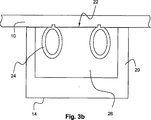
インダクタ14は、封止中に封止ゾーン内で積層品と当接することになる作用面22を有する絶縁体20を備える(図3a参照)。作用面22内には、導体24が埋め込まれ、前記導体24は、封止中に積層品と接触するように設けられる(図3b参照)。導体24は、導電材料、すなわち抵抗率の低い材料で製造され、好ましくは冷却チャネルを備える。好ましくは、導体24は、銅から製造することができる。さらに、導体24は、各端部が交流電源18に結合される開ループ(open loop)の形態を有する(図3a参照)。ループ全体は、包装材料積層品と接触するように適合される。すなわち、ループの平面が包装材料積層品の平面に対して実質的に平行である。さらに、ループは、細長いものであり、シールジョー14の長手方向延長部に沿って延びる。電流接続部が配置されるループ内の開口は、細長いシールジョー14の一端内で位置決めされる。
The
一方、絶縁体20は、透磁率特性のある、又は透磁率特性のない絶縁性の非導電材料から製造される。好ましくは、プラスチック材料又はセラミックを使用することができる。磁界の強度を高めるために、また、磁力線を導くために、透磁性材料を絶縁体20内に設けることができる。1つのやり方は、絶縁体20にフェライト粉末を与えることである。この粉末は、プラスチック絶縁体又はセラミック絶縁体の成形中に追加することができる。別のやり方は、μ=10〜2500の範囲内の透磁率値を有する材料のインサート(insert)26を使用することである。好ましくは、たとえばFerrotron(商標)、又はその範囲の上部内の値を有する材料のインサート26を、絶縁体20内で、導体24付近で設けることができる。この技法は、誘導封止技術内のものと同様である。
On the other hand, the
封止中には、シールジョー14がアンビル16と協働している(図2参照)。この実施例では、アンビル14は導電性であるが受動的である、すなわち電源に接続されない。アンビル16の一実施形態について、図2及び図4を参照して述べる。アンビル16は、封止中にシールジョー14の作用面22に面するように適合された、対応する作用面28を有する(図3bを比較されたい)。さらに、前記アンビル16は、絶縁体30から作製され、その絶縁体30は、導体32を備える。前記導体32は、導電材料、すなわち抵抗率の低い材料、好ましくは銅製である。導体32は、包装材料積層品と接触するよう適合されるように、絶縁体30の作用面28内で埋め込まれる。別法として、導体32は、包装材料積層品が導体と直接接触することから保護するために、少なくとも作用面22内で、たとえばゴムの層によって覆うことができる。さらに、導体32は、閉ループ(closed loop)の形態を有する。ループ全体は、包装材料積層品と接触するように適合される。すなわち、ループの平面が包装材料積層品の平面に対して実質的に平行である。さらに、ループは、細長いものであり、アンビルの長手方向延長部に沿って延びる。アンビル16の絶縁体30は、シールジョー14の絶縁体20と同様のものとすることができる。絶縁体30は、透磁率特性のある、又は透磁率特性のない絶縁性の非導電材料から製造される。好ましくは、プラスチック材料又はセラミックを使用することができる。透磁性材料を絶縁体30内に設けることができる。絶縁体が(プラスチック絶縁体又はセラミック絶縁体の成形中に追加された)フェライト粉末を備える、或いは、ある透磁率値を有する材料のインサート(図示せず)が使用される。インサート材料は、μ=10〜2500の範囲内の透磁率値を有することができる。好ましくは、たとえばFerrotron(商標)のインサートを使用することができる。
During sealing, the sealing
シールジョー16及びアンビル14は、封止圧力を包装材料積層品に加え、封止ゾーン内でそれらを共に押圧するように設けられる。圧力を加えるやり方は当技術分野で周知であり、本明細書ではこれ以上述べない。
2つの包装材料積層品10、12を共に封止するとき、第1の積層品10の封止可能な層34が、他方の積層品12に面して配置される。次いで、シールジョー14及びアンビル16が、積層品10、12を互いに向かって押圧する。その後で、シールジョー14の導体24に交流が供給される。電流により、積層品10、12の封止ゾーン内で磁界が生成される。磁力線は、積層品10、12の平面36に対して実質的に平行になる。磁力線の方向については、下記でさらに述べる。前記磁界は、積層品内の磁化可能な粒子に影響を及ぼし、これについては導入部内で述べられており、ヒステリシス損失によるエネルギーにより、封止可能な層34が溶融する。ヒステリシス損失によるエネルギーは、5〜50ジュールの範囲内にあり、おそらくは約10ジュールとなる。
When the two packaging material laminates 10, 12 are sealed together, the
動作中には、包装材料積層品10、12の他方の側にあるシールジョー14内のインダクタのため、電流がアンビル16内で誘導される。誘導される電流により磁界が生成され、その磁界は、シールジョー14のインダクタによって印加される磁界の強度及び方向を強めることになる。
In operation, current is induced in the
この実施形態では、磁界が印加されたとき、封止圧力が実質的に同時に加えられる。これは、封止圧力が磁界と同時に、又はわずかに前後して加えられる可能性があることを意味する。好ましくは、封止圧力は、磁界が印加される前に加えられる。別法として、いくつかの応用例では、磁界と圧力は、(別個の手段によって)別々に、且つ順次加えられてよい。第1のステップでは磁界が加えられる可能性があり、それによって積層品が加熱されたとき、第2のステップで封止圧力が加えられる。異なる手段を使用し、磁界及び封止圧力を加えることができる。 In this embodiment, the sealing pressure is applied substantially simultaneously when a magnetic field is applied. This means that the sealing pressure may be applied at the same time as the magnetic field or slightly before and after. Preferably, the sealing pressure is applied before the magnetic field is applied. Alternatively, in some applications, the magnetic field and pressure may be applied separately and sequentially (by separate means). In the first step, a magnetic field may be applied, whereby when the laminate is heated, sealing pressure is applied in the second step. Different means can be used to apply the magnetic field and sealing pressure.
封止ゾーンが封止された、すなわち封止可能な層34が溶融されたとき、磁界の印加が途絶える。好ましくは、封止圧力は、冷却するための短時間の間維持される。この時間は、100〜200ミリ秒の範囲内にあるものとすることができる。冷却手順は、他の封止技術から周知である。
When the sealing zone is sealed, i.e. the
ヒステリシス損失による放散されたエネルギーは、周波数に直接比例することが判明している。さらに、周波数と封止時間との関係は、実質的に線形であることが判明している。したがって、周波数が減少された場合、封止時間を増大しなければならないことになる。さらに、粒子濃度と封止時間との関係は、実質的に線形であることが判明している。したがって、積層品内の粒子の量が多くなると、封止時間が減少することになり、逆も同様である。 It has been found that the energy dissipated by hysteresis loss is directly proportional to frequency. Furthermore, the relationship between frequency and sealing time has been found to be substantially linear. Therefore, if the frequency is reduced, the sealing time must be increased. Furthermore, the relationship between particle concentration and sealing time has been found to be substantially linear. Therefore, as the amount of particles in the laminate increases, the sealing time decreases and vice versa.
使用することができる磁化可能な粒子は、マグネタイトFe3O4である。約0.5μmの平均粒子サイズ(Hoganasから入手される粒子、X−MP4)を用いて試行されている。結果は、肯定的である。他の材料及び粒子サイズもまた、当然ながら使用することができる。しかし、粒子を選択するときには注意すべきである。一部の種類には、法律により食品包装で使用することができないものもあれば、それらを製造することにより、より高いコストを必要とするものもある。現在、0.5μmより小さい粒子の製造は、より複雑な製造プロセスを必要とする。 A magnetizable particle that can be used is magnetite Fe 3 O 4 . Tried with an average particle size of about 0.5 μm (particles obtained from Hoganas, X-MP4). The result is positive. Other materials and particle sizes can of course also be used. However, care should be taken when selecting the particles. Some types cannot be used in food packaging by law, while others require higher costs by manufacturing them. Currently, the production of particles smaller than 0.5 μm requires a more complex manufacturing process.
述べられているタイプ(Fe3O4、粒子サイズ約0.5μm)の磁性粒子が各積層品内のポリエチレン(PE)層内に含まれる試料が作製されている。PE層内の磁性粒子の量は、約17g/m2である。2MHzの周波数を使用し、磁気飽和レベルに近い磁界強度を適用すると、2つの積層品10、12を共に適正に封止するための封止時間は、約100ミリ秒となる。磁性粒子の他の量、並びに粒子の他のサイズ及び他の包装材料積層品は、異なる封止時間、及び/又は異なる周波数を必要とすることになることを理解されたい。
Samples have been made in which magnetic particles of the stated type (Fe 3 O 4 , particle size of about 0.5 μm) are contained in a polyethylene (PE) layer in each laminate. The amount of magnetic particles in the PE layer is about 17 g / m 2 . When a frequency of 2 MHz is used and a magnetic field strength close to the magnetic saturation level is applied, the sealing time for properly sealing the two
図5は、シールジョー14、包装材料積層品10、12、アンビル16、及び封止ゾーン内の磁界の横断面を概略的に示す。横断面のため、シールジョー14の導体24、及びアンビル16の導体32は、それぞれ2つの円として示されている。これらの円内で、電流の瞬間的な方向が示されている。矢印は磁力線を表しており、包装材料積層品10、12付近の主磁力線は、包装材料積層品10、12の平面36と実質的に平行であることがわかる。さらに、アンビル16からの貢献により、シールジョー14によって生成される磁界が強められつつあることがわかる。アンビル16からの磁界を表す矢印もまた、包装材料積層品10、12の平面36と実質的に平行であり、シールジョー14の磁力線と同じ方向で導かれる。
FIG. 5 schematically shows a cross section of the magnetic field in the sealing
図6a及び図6bでは、ヒステリシスループが示されている。図6aは、上記の場合、すなわち磁界が包装材料積層品の平面と平行で印加される場合について述べ、一方、図6bは、磁界が包装材料積層品の平面に対して垂直に印加される場合について述べている。2つの領域は、実質的にサイズが同様であること、しかし図6bにおける領域を得るために必要とされる磁界の方が高く、実際、ほぼ2倍であることがわかる。したがって、磁界を包装材料積層品に対して実質的に平行に印加する方が効率的であると結論することができる。 In FIGS. 6a and 6b, a hysteresis loop is shown. Fig. 6a describes the above case, i.e. where the magnetic field is applied parallel to the plane of the packaging material laminate, while Fig. 6b shows the case where the magnetic field is applied perpendicular to the plane of the packaging material laminate. About. It can be seen that the two regions are substantially similar in size, but the magnetic field required to obtain the region in FIG. Therefore, it can be concluded that it is more efficient to apply a magnetic field substantially parallel to the packaging material laminate.
「包装材料積層品の平面と平行」という表現には、包装材料が封止ゾーン内で湾曲する場合も含めるべきである。したがって、磁力線は、湾曲に従うように、すなわち湾曲内の点のそれぞれの接線に対して実質的に平行となるように導くべきである。 The expression “parallel to the plane of the packaging material laminate” should also include the case where the packaging material is curved in the sealing zone. Thus, the magnetic field lines should be guided to follow the curvature, i.e. substantially parallel to the respective tangent of each point in the curvature.
本発明について、本発明の現在の好ましい実施形態に従って述べた。しかし、本発明は、この実施形態に限定されず、同封の特許請求の範囲内でいかなる形でも修正することが可能であることを理解されたい。 The invention has been described according to the presently preferred embodiment of the invention. However, it is to be understood that the invention is not limited to this embodiment and can be modified in any manner within the scope of the enclosed claims.
たとえば、この実施形態では、第1及び第2の積層品10、12について述べた。しかし、第1及び第2の積層品は、同じ積層品の第1及び第2の部分10、12とすることができることを理解されたい。たとえば、矩形のブランク又はウェブが、スリーブ又は管の形に形成され、重なり合うジョイント領域38内で、2つの長手方向の縁部に沿って封止されることになる。したがって、第1の積層品10は、第1の縁部に沿ってブランクの一部分を構成することになり、一方、第2の積層品12は、第2の縁部に沿ってブランクの一部分を構成することになる。図7は、管状のスリーブの形に形成されるブランクを示している。領域38は、その後で、封止されることになる重ね合わせを生み出すことになる。
For example, in this embodiment, the first and second
本封止方法は、図のジョイント、すなわち、2つの積層品が、それらの内側(又は外側)表面が互いに面した状態で互いに当接しているジョイントのようなジョイントを封止するとき使用することができる。また、一方の積層品の外側表面が他方の積層品の内側表面に当接しており、重ね合わせを形成する、重なり合うジョイントを封止するために使用することもできる。 This sealing method should be used when sealing the joints in the figure, ie joints where the two laminates are in contact with each other with their inner (or outer) surfaces facing each other. Can do. Also, the outer surface of one laminate can abut the inner surface of the other laminate and can be used to seal overlapping joints that form an overlay.
この説明では、封止圧力及び磁界が、1つの同じ装置、すなわちシールジョー14とアンビル16の対によって加えられる。しかし、圧力及び磁界は、異なる装置によって加えることができることを理解されたい。すなわち、磁界と圧力が別々に加えられる。
In this description, the sealing pressure and magnetic field are applied by one and the same device, ie, a pair of sealing
述べられている実施形態では、シールジョー14は、交流電源18に接続された導体24を備えるインダクタである。述べられているアンビル16は、導電性且つ受動的である、すなわちどの電源にも接続されないが、シールジョー14の導体24内の電流に応答して電流を誘導することが可能であるように構成される導体32を備える。しかし、アンビル16は、導電性のタイプの、しかし能動的なものとすることができることを理解されたい。したがって、シールジョー14と同じタイプのもの、すなわち交流電源に接続されることになる。シールジョー14及びアンビル16は、同じ制御及び供給するための電力システムに接続することも、別個のシステムに接続することもできる。
In the described embodiment, the sealing
他の実施形態では、アンビルは、導体として銅板の形態で構成することができる。銅板は、包装材料積層品と直接接触させることも、たとえば保護用ゴムの層によって覆うこともできる。ゴムは、少なくとも導電銅板と包装材料積層品の間に設けられることになる。すなわち、アンビルの作用面がゴム内にあることになり、包装材料が、この導電板と間接接触することになる。 In other embodiments, the anvil can be configured in the form of a copper plate as a conductor. The copper plate can be brought into direct contact with the packaging material laminate or can be covered, for example, by a layer of protective rubber. The rubber is provided at least between the conductive copper plate and the packaging material laminate. That is, the working surface of the anvil is in the rubber, and the packaging material is in indirect contact with the conductive plate.
別法として、アンビル16は、どのような導電能力もなしに製造することができる。すなわち、アンビル16は、絶縁体であり、たとえばゴム製となる。しかし、そのときには、当然ながら磁界を強めることは可能でないことになる。
Alternatively, the
Claims (13)
封止ゾーン内で前記積層品(10、12)に交流磁界を与え、それによって、磁気ヒステリシス損失を、前記磁化可能な粒子を含む前記積層品(10)内で生成し、前記損失が、前記封止ゾーン内で前記封止可能な層(34)を実質的に溶融する熱を生み出すこと、及び、
封止圧力を前記第1及び第2の積層品(10、12)に加え、前記圧力により、前記第1と第2の積層品(10、12)が前記封止ゾーン内で互いに押圧され、それによって前記積層品(10、12)を互いに封止することを特徴とし、
さらに、前記交流磁界を、少なくともシールジョー(14)によって与える工程と、
前記磁界を、導電性アンビル(16)を使用することによって強める工程と、
前記アンビル(16)を前記シールジョー(14)に対して反対側で設ける工程とを含み、
前記シールジョー(14)が、交流電源(18)に接続された導体(24)を備えるインダクタであり、
前記アンビル(16)が受動的であり、前記シールジョー(14)内の電流に応答して電流を誘導することが可能であり、それによって、前記シールジョー(14)によって生成される前記磁界を強める磁界を生成する、上記方法。A method for sealing a first packaging material laminate (10) to a second packaging laminate (12), wherein at least the first laminate (10) is at least one layer of magnetizable particles. And a sealable layer (34),
An alternating magnetic field is applied to the laminate (10, 12) in a sealing zone, thereby generating a magnetic hysteresis loss in the laminate (10) containing the magnetizable particles, the loss being Creating heat that substantially melts the sealable layer (34) in a sealing zone; and
Applying sealing pressure to the first and second laminates (10, 12), the pressure causes the first and second laminates (10, 12) to be pressed together in the sealing zone, Thereby, the laminates (10, 12) are sealed together,
And applying the alternating magnetic field by at least a sealing jaw (14);
Enhancing the magnetic field by using a conductive anvil (16);
Providing the anvil (16) on the opposite side of the sealing jaw (14),
The sealing jaw (14) is an inductor comprising a conductor (24) connected to an AC power source (18);
The anvil (16) is passive and can induce a current in response to the current in the sealing jaw (14), thereby reducing the magnetic field generated by the sealing jaw (14). A method as described above , which generates a magnetic field for strengthening .
封止ゾーン内で前記積層品(10、12)に交流磁界を与え、それによって、磁気ヒステリシス損失を、前記磁化可能な粒子を含む前記積層品(10)内で生成する手段(14)であって、前記損失が、前記封止ゾーン内で前記封止可能な層(34)を実質的に溶融する熱を生み出す、当該手段(14)と、
封止圧力を前記第1及び第2の積層品(10、12)に加える手段(14、16)であって、前記圧力により、前記第1と第2の積層品(10、12)が前記封止ゾーン内で互いに押圧され、それによって前記積層品(10、12)を互いに封止する、当該手段(14、16)とを備え、
前記交流磁界を与えるように適合された前記手段(14)が、交流電源(18)に接続された導体(24)を備えるインダクタの形態にあるシールジョー(14)であり、
導電性アンビル(16)が、前記磁界を強めるように設けられ、
前記アンビル(16)が、前記シールジョー(14)内の電流に応答して電流を誘導するように適合された導体(32)を備え、それによって、前記シールジョー(14)によって生成される前記磁界を強める磁界を生成することを特徴とする、装置。An apparatus for sealing a first packaging material laminate (10) to a second packaging laminate (12), wherein at least the first laminate (10) is at least one layer of magnetizable particles. And a sealable layer (34),
Means (14) for applying an alternating magnetic field to the laminate (10, 12) in a sealing zone, thereby generating a magnetic hysteresis loss in the laminate (10) comprising the magnetizable particles. The means (14) wherein the loss creates heat that substantially melts the sealable layer (34) in the sealing zone;
Means (14, 16) for applying a sealing pressure to the first and second laminates (10, 12), the pressure causing the first and second laminates (10, 12) to be Said means (14, 16), pressed against each other in a sealing zone, thereby sealing the laminates (10, 12) together ,
The means (14) adapted to provide the alternating magnetic field is a sealing jaw (14) in the form of an inductor comprising a conductor (24) connected to an alternating current power source (18);
A conductive anvil (16) is provided to enhance the magnetic field;
The anvil (16) comprises a conductor (32) adapted to induce a current in response to the current in the sealing jaw (14), thereby generating the sealing jaw (14). An apparatus for generating a magnetic field that enhances a magnetic field .
Applications Claiming Priority (2)
| Application Number | Priority Date | Filing Date | Title |
|---|---|---|---|
| SE0403038A SE0403038D0 (en) | 2004-12-14 | 2004-12-14 | Device and method of sealing |
| PCT/SE2005/001911 WO2006065211A1 (en) | 2004-12-14 | 2005-12-13 | Method and device for sealing |
Publications (2)
| Publication Number | Publication Date |
|---|---|
| JP2008522922A JP2008522922A (en) | 2008-07-03 |
| JP4568761B2 true JP4568761B2 (en) | 2010-10-27 |
Family
ID=33563203
Family Applications (1)
| Application Number | Title | Priority Date | Filing Date |
|---|---|---|---|
| JP2007546606A Expired - Fee Related JP4568761B2 (en) | 2004-12-14 | 2005-12-13 | Method and apparatus for sealing |
Country Status (9)
| Country | Link |
|---|---|
| US (2) | US20080110560A1 (en) |
| EP (1) | EP1833673A4 (en) |
| JP (1) | JP4568761B2 (en) |
| CN (1) | CN101080323B (en) |
| BR (1) | BRPI0518545A2 (en) |
| MX (1) | MX2007005930A (en) |
| RU (1) | RU2389607C2 (en) |
| SE (1) | SE0403038D0 (en) |
| WO (1) | WO2006065211A1 (en) |
Families Citing this family (16)
| Publication number | Priority date | Publication date | Assignee | Title |
|---|---|---|---|---|
| CN102448830B (en) * | 2009-05-29 | 2014-06-25 | 利乐拉瓦尔集团及财务有限公司 | Packaging material comprising magnetisable portions |
| DE102010060941A1 (en) * | 2010-12-01 | 2012-06-06 | Nilos Gmbh & Co. Kg | Method for connecting conveyor belts with steel cable inserts by vulcanization |
| US9370895B1 (en) * | 2012-03-22 | 2016-06-21 | Amazon Technologies, Inc. | Magnetic field induction bonding technique |
| WO2014099219A1 (en) * | 2012-12-17 | 2014-06-26 | Dow Global Technologies Llc | A multi-layered structure and a method of sealing or shaping using a multi-layered structure |
| EP3131739B1 (en) * | 2014-04-16 | 2020-10-07 | Tetra Laval Holdings & Finance SA | Induction sealing device and method of sealing a packaging material using said induction sealing device |
| WO2016083212A1 (en) | 2014-11-24 | 2016-06-02 | Tetra Laval Holdings & Finance S.A. | Simplified transversal induction sealing device |
| EP3380304A1 (en) | 2015-11-27 | 2018-10-03 | Tetra Laval Holdings & Finance S.A. | A sealing device with increased robustness |
| EP3241667B1 (en) | 2016-05-02 | 2020-07-08 | Tetra Laval Holdings & Finance S.A. | Improved induction sealing system |
| US11554555B2 (en) | 2017-05-30 | 2023-01-17 | Tetra Laval Holdings & Finance S.A. | Apparatus for sealing the top of a package for a food product and system for forming and filling a food package |
| US10899082B2 (en) | 2017-07-17 | 2021-01-26 | Tetra Laval Holdings & Finance S.A. | Inductor coil for induction welding of a packaging material |
| JP2020527519A (en) | 2017-07-18 | 2020-09-10 | テトラ ラバル ホールディングス アンド ファイナンス エス エイ | Induction seal device |
| RU184919U1 (en) * | 2018-06-13 | 2018-11-14 | Федеральное государственное бюджетное учреждение науки Институт проблем нефти и газа Сибирского отделения Российской академии наук | Device for welding ultra high molecular weight polyethylene |
| EP3620293B1 (en) | 2018-09-10 | 2021-12-08 | Tetra Laval Holdings & Finance S.A. | A method for forming a tube and a method and a packaging machine for forming a package |
| US11820540B2 (en) | 2018-09-11 | 2023-11-21 | Tetra Laval Holdings & Finance S.A. | Packaging apparatus for forming sealed packages |
| US10766672B2 (en) | 2018-12-12 | 2020-09-08 | Yeti Coolers, Llc | Insulating container |
| JP2024500201A (en) * | 2020-12-22 | 2024-01-05 | テトラ ラバル ホールディングス アンド ファイナンス エス エイ | induction heating sealing device |
Family Cites Families (19)
| Publication number | Priority date | Publication date | Assignee | Title |
|---|---|---|---|---|
| US3461014A (en) * | 1964-06-11 | 1969-08-12 | Albert L James | Magnetic induction method for heat-sealing and bonding predetermined sealing areas |
| US3730804A (en) * | 1971-07-20 | 1973-05-01 | Fifth Third Bank | Method of heat sealing a pair of closures with a magnetic susceptible material and high frequency alternating and steady magnetic fields |
| US3879247A (en) * | 1971-07-20 | 1975-04-22 | Harrington Research Corp | Method of heat sealing and holding package closure elements |
| US3802985A (en) * | 1972-01-06 | 1974-04-09 | Heller W | Heatable stratified material and manufacturing method therefor |
| AU3951678A (en) | 1977-09-13 | 1980-03-13 | Heller, William C. Jr. | Fusion bonding non-elastomeric thermoplastic elements |
| JPS60125643A (en) * | 1983-12-07 | 1985-07-04 | Kishimoto Akira | Thermal adhesion |
| US4602139A (en) * | 1984-09-28 | 1986-07-22 | Hutton Roger L | Induction bonding method and apparatus |
| JPS61242827A (en) * | 1985-04-19 | 1986-10-29 | Seidensha Denshi Kogyo Kk | Welding device for laminated cylinder member |
| SE451974B (en) * | 1985-08-22 | 1987-11-09 | Tetra Pak Ab | SET AND DEVICE FOR INDUCTION SEALING THERMOPLAST COATED PACKAGING MATERIAL INCLUDING ATMINSTONE ONE LAYER OF METAL WRAP |
| US4969968A (en) * | 1988-07-22 | 1990-11-13 | William C. Heller, Jr. | Method of inductive heating with an integrated multiple particle agent |
| SE500572C2 (en) * | 1990-10-11 | 1994-07-18 | Tetra Laval Holdings & Finance | Device for induction welding |
| US5248864A (en) | 1991-07-30 | 1993-09-28 | E. I. Du Pont De Nemours And Company | Method for induction heating of composite materials |
| US5807549A (en) * | 1993-05-21 | 1998-09-15 | Research Corporation Technologies, Inc. | Lymphocyte chemoattractant factor and uses thereof |
| JPH079591A (en) | 1993-06-23 | 1995-01-13 | Nippon Tetrapack Kk | Wrapping material |
| SE506190C2 (en) | 1996-03-20 | 1997-11-17 | Tetra Laval Holdings & Finance | Apparatus and method for induction sealing of thermoplastic coated packaging material |
| US6939477B2 (en) * | 1997-06-06 | 2005-09-06 | Ashland, Inc. | Temperature-controlled induction heating of polymeric materials |
| US6056844A (en) * | 1997-06-06 | 2000-05-02 | Triton Systems, Inc. | Temperature-controlled induction heating of polymeric materials |
| JP2000168737A (en) * | 1998-12-11 | 2000-06-20 | Toppan Printing Co Ltd | Hermetical sealing of paper container, and forming device using the same method |
| SE524370C2 (en) | 2002-05-10 | 2004-08-03 | Tetra Laval Holdings & Finance | Packaging laminate, big roll, and a layer for use with a packaging laminate |
-
2004
- 2004-12-14 SE SE0403038A patent/SE0403038D0/en unknown
-
2005
- 2005-12-13 MX MX2007005930A patent/MX2007005930A/en unknown
- 2005-12-13 JP JP2007546606A patent/JP4568761B2/en not_active Expired - Fee Related
- 2005-12-13 EP EP05815742A patent/EP1833673A4/en not_active Withdrawn
- 2005-12-13 RU RU2007126840A patent/RU2389607C2/en not_active IP Right Cessation
- 2005-12-13 CN CN2005800428121A patent/CN101080323B/en not_active Expired - Fee Related
- 2005-12-13 WO PCT/SE2005/001911 patent/WO2006065211A1/en active Application Filing
- 2005-12-13 US US11/792,070 patent/US20080110560A1/en not_active Abandoned
- 2005-12-13 BR BRPI0518545-9A patent/BRPI0518545A2/en not_active IP Right Cessation
-
2010
- 2010-12-30 US US12/982,345 patent/US8366859B2/en not_active Expired - Fee Related
Also Published As
| Publication number | Publication date |
|---|---|
| RU2389607C2 (en) | 2010-05-20 |
| US8366859B2 (en) | 2013-02-05 |
| BRPI0518545A2 (en) | 2008-11-25 |
| CN101080323A (en) | 2007-11-28 |
| EP1833673A4 (en) | 2011-09-28 |
| RU2007126840A (en) | 2009-01-27 |
| EP1833673A1 (en) | 2007-09-19 |
| CN101080323B (en) | 2010-06-16 |
| WO2006065211A1 (en) | 2006-06-22 |
| SE0403038D0 (en) | 2004-12-14 |
| MX2007005930A (en) | 2007-09-27 |
| US20080110560A1 (en) | 2008-05-15 |
| JP2008522922A (en) | 2008-07-03 |
| US20110094672A1 (en) | 2011-04-28 |
Similar Documents
| Publication | Publication Date | Title |
|---|---|---|
| JP4568761B2 (en) | Method and apparatus for sealing | |
| US3864186A (en) | Method for induction sealing packaging material | |
| JP3631268B2 (en) | Device for sealing packaging material coated with thermoplastics | |
| US4704509A (en) | Induction apparatus and method for sealing of thermoplastic coated packing material | |
| EP3131739B1 (en) | Induction sealing device and method of sealing a packaging material using said induction sealing device | |
| US10737443B2 (en) | Device and method for inductive sealing of a plurality of plies of a laminate | |
| RU2702839C2 (en) | Device and method for induction heating of packages bodies | |
| HK1075862A1 (en) | Heat-sealing device for packaging material | |
| US4371768A (en) | Arrangement for the sealing of thermoplastic-coated packing material | |
| JP3768477B2 (en) | Package or packaging material manufacturing equipment | |
| CN109263055B (en) | Induction sealing device | |
| US4571472A (en) | Device for induction welding | |
| EP0480405A1 (en) | An apparatus for induction welding | |
| US6875965B2 (en) | Multiple head induction sealer apparatus and method | |
| US3510619A (en) | Apparatus for induction heating | |
| WO2013093505A2 (en) | Apparatus and method | |
| WO2015078907A1 (en) | An induction heating device | |
| US7675009B2 (en) | Electrode for machines for electromagnetic induction welding of the layers forming a multi-layer printed circuit | |
| JP7402741B2 (en) | Fusion method and joined body | |
| SE502829C2 (en) | Induction welding device for sealing thermoplastic material base or lid onto end of packaging container | |
| JP2024500201A (en) | induction heating sealing device |
Legal Events
| Date | Code | Title | Description |
|---|---|---|---|
| RD04 | Notification of resignation of power of attorney |
Free format text: JAPANESE INTERMEDIATE CODE: A7424 Effective date: 20080716 |
|
| A131 | Notification of reasons for refusal |
Free format text: JAPANESE INTERMEDIATE CODE: A131 Effective date: 20100316 |
|
| A521 | Written amendment |
Free format text: JAPANESE INTERMEDIATE CODE: A523 Effective date: 20100526 |
|
| TRDD | Decision of grant or rejection written | ||
| A01 | Written decision to grant a patent or to grant a registration (utility model) |
Free format text: JAPANESE INTERMEDIATE CODE: A01 Effective date: 20100730 |
|
| A01 | Written decision to grant a patent or to grant a registration (utility model) |
Free format text: JAPANESE INTERMEDIATE CODE: A01 |
|
| A61 | First payment of annual fees (during grant procedure) |
Free format text: JAPANESE INTERMEDIATE CODE: A61 Effective date: 20100809 |
|
| R150 | Certificate of patent or registration of utility model |
Free format text: JAPANESE INTERMEDIATE CODE: R150 |
|
| FPAY | Renewal fee payment (event date is renewal date of database) |
Free format text: PAYMENT UNTIL: 20130813 Year of fee payment: 3 |
|
| R250 | Receipt of annual fees |
Free format text: JAPANESE INTERMEDIATE CODE: R250 |
|
| R250 | Receipt of annual fees |
Free format text: JAPANESE INTERMEDIATE CODE: R250 |
|
| R250 | Receipt of annual fees |
Free format text: JAPANESE INTERMEDIATE CODE: R250 |
|
| LAPS | Cancellation because of no payment of annual fees |