JP4566355B2 - Elevator car - Google Patents
Elevator car Download PDFInfo
- Publication number
- JP4566355B2 JP4566355B2 JP2000223315A JP2000223315A JP4566355B2 JP 4566355 B2 JP4566355 B2 JP 4566355B2 JP 2000223315 A JP2000223315 A JP 2000223315A JP 2000223315 A JP2000223315 A JP 2000223315A JP 4566355 B2 JP4566355 B2 JP 4566355B2
- Authority
- JP
- Japan
- Prior art keywords
- car
- plate
- bracket
- car panel
- bolt
- Prior art date
- Legal status (The legal status is an assumption and is not a legal conclusion. Google has not performed a legal analysis and makes no representation as to the accuracy of the status listed.)
- Expired - Lifetime
Links
Images


Description
【0001】
【発明の属する技術分野】
この発明はエレベータかごに係り、特に方形板状のプラットホーム(かご床)の三辺にカーパネル(壁板)を組み付けて側壁部を形成する型式のエレベータかごに関する。
【0002】
【従来の技術】
エレベータかごは方形板状のプラットホームの三辺をカーパネルで覆い、残りの一辺には開閉するカードアが設けられ、かつ、天井部は閉じられた箱状体であって、その屋上部に吊支索が連結されて建物の昇降路内に上下動可能に収納され、その内部の乗客等を階層間で輸送する手段である。
【0003】
従来、このエレベータかご1の三辺に形成する側壁部は、図10に示すように、方形板状のプラットホーム2の下部のフレーム3の側面に、あらかじめボルト30を所定間隔にて取り付けておき、このボルト30に長方形板状のカーパネル6の下縁に形成した略逆V字形の切欠部からなるスロット穴6aを嵌め込んで仮置きし、かご下(ピット)又はかご外の昇降路内に作業員が移って最終的なボルト締結作業を行うようになっていた。
【0004】
【発明が解決しようとする課題】
しかしながら、近時、エレベータかごは大型化する傾向にある反面、昇降路はなるべく小さく合理的に設計されるので、かごと昇降路との隙間に作業員が入り込んで作業できるのに十分なスペースがなく、作業し難くなっている。また、かごと昇降路との隙間に入り込んで作業するのは姿勢が不自然になり、とりわけ、かご下からの作業は上向き姿勢となって能率が低下するから、時間を要して工期を遅らせるなどの不都合が生じている。
【0005】
そこで、この発明は、作業員が昇降路内に入り込むことなく、かご内でカーパネルを自然な姿勢にてプラットホームに組付けることができるようにすることを目的とする。
【0006】
【課題を解決するための手段】
この発明にかかるエレベータかごは、方形板状のプラットホームの三辺の下部に固定したフレームの側面にプレートを、密接かつ平行し上部が突出する段違いで固定するとともに、該プレートに当接する溝型材からなるブラケットをカーパネルの下部背面に平行に固定し、前記プレートとブラケットとを貫通するボルト孔を穿設し、かつ、前記カーパネルの正面にはブラケットのボルト孔と対面してボルト頭が挿通可能な透孔を穿設し、エレベータかご内でボルトを前記透孔を介しボルト孔に挿通して前記プレートとブラケットを締結することにより、エレベータかご内でカーパネルの全組付け作業ができるようにしたことを特徴とする。
【0007】
したがって、作業員はエレベータかご内でカーパネル下部のブラケットをプラットホームのフレームのプレートに当て、それら両者のボルト孔を合わせてカーパネルを立設し、かつ、カーパネルの透孔からボルトをボルト孔に挿通し治具で回し込んでブラケットとプレートとを締結する。ボルト頭は透孔からブラケットの溝内に没して溝底に当接する。この透孔はキックプレートを設けることによって隠蔽されるので、意匠的な不具合はない。
【0008】
【発明の実施の形態】
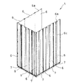
以下、この発明の実施の形態を図に基づき説明する。図1に示すように、この発明のエレベータかご1は、方形板状のプラットホームの三辺にカーパネルを立設固定して側壁部が形成される型式で、その側壁部は、所定のカーパネル6の複数枚を縦横三辺に立設して正面が開口した箱状体を形成している。カーパネル6は従来のものとは構造を異にし、カーパネル6の下部にブラケット7を結合してあり、そのブラケット7がボルト等にて、図2及び図3に示すように、かご内のプラットホーム2を固定したフレーム3の側面に固定したプレート4に連結する構造としている。
【0009】
すなわち、図2及び図3に示すように、方形板状をしたプラットホーム2を固定するフレーム3の三辺の側面に、それぞれプレート4をボルト5又は溶接にて適宜固定する。プレート4はフレーム3と密接かつ平行し上部が突出する段違いで固定する。
【0010】
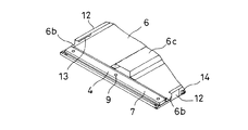
一方、プレート4に当接する溝型材からなるブラケット7をカーパネル6の下部背面に平行に固定する。ブラケット7はカーパネル6の背面に溶接等にて適宜あらかじめ固定されている。このブラケット7の両端部側のカーパネル6の側端部12,12はプレート4と干渉しないように切欠部6b,6b(図5参照)として形成してある。また、カーパネル6の背面には補強部6cが長手方向に結合され、上部には天井部に連結するためのスロット穴6aとナット6dを固定した孔が設けられている。
【0011】
そして、プレート4にはねじ孔又はナット8を固定したボルト孔が長手方向へ所定間隔で複数個にて穿設され、また、ブラケット7にはそれらに対応するボルト孔9が所定間隔で複数個にて穿設されている。さらに、カーパネル6の正面にはブラケット7のボルト挿通孔9と対面してボルト頭が挿通可能な透孔10が開設されている。
【0012】
そこで、カーパネル6をプラットホーム4の三辺に立設してエレベータかご1を形成する組付け作業に当たり、作業員はプラットホーム2内において、図2に示すように、カーパネル6の下部のブラケット7をプレート4に当て、ボルト孔9をプレート4のナット8を固定したボルト孔に合わせ、図3に示すように、カーパネル6,6の下部の透孔10からボルト11をボルト孔9及びナット8を固定したボルト孔に挿通し、治具にてボルト頭が透孔10から没するように回し込んでブラケット7の溝底に当接せしめ、ブラケット7をプレート4に締結する。
この作業によって、図1及び図8に示すように、カーパネル6はフレーム3に固定され、プラットホーム2に直交した垂直のエレベータかご1の側壁部が形成される。
【0013】
なお、カーパネル6の長手方向の両側部は互いに接面する側端部12が直角に曲げ形成されており、かつ、その側端部12には隣接どうしで互いに対面する変形長孔13とボルト14が所定間隔の複数個にて設けられている。変形長孔13は長孔の上下端部に拡径円孔を連続形成した形状である。そこで、カーパネル6を立設するまず初めに、隣接する一方の側端部12の変形長孔13の拡径円孔に、隣接して立設すべきカーパネル6の側端部12のボルト14を合わせて挿入し、図9(A)に示すように、立設すべきカーパネル6の上下動にてボルト14を長孔に移動させて位置調整を行い、かつ、図9(B)に示すように、ナット15で締め付けることで隣接するカーパネル6,6を連結する。
【0014】
このように、カーパネル6でプラットホーム2の三辺に側壁部を形成した後、透孔10を覆うキックプレート(裾板)をプラットホーム2上でカーパネル6の下部に張設して隠蔽できるから、透孔10の意匠的見地による弊害は生じない。
【0015】
なお、カーパネル6の上部の結合構造については図示しないが、上記した下部同様に構成してもよい。しかしながら、エレベータかご1の屋上部には滑車などの機器を搭載するために台が形成され、その台にて下向き作業可能な空間が確保できるから、敢えて下部と同じ構成にする必要性に乏しく、図4及び図6に示すように、従来と同じ構成で足りるのである。
【0016】
かくして、従来のカーパネルの一部に変更を加えてブラケット7を設ける一方、そのブラケット7が当接するプレート4をフレーム3に設けることで、作業員はエレベータかご1内でカーパネル6の全組付け作業を簡便迅速かつ容易に、完了することができる。
【0017】
【発明の効果】
以上説明したこの発明によれば、エレベータかごのカーパネル組付けに当たり、作業員はエレベータかご内で自然な姿勢で作業ができ、昇降路内に入り込む必要性を一切無くしたから、作業能率が向上して据え付け性も向上し、工期の短縮ができる。
【図面の簡単な説明】
【図1】本発明におけるエレベータかごの側壁部を示す背面側斜視図。
【図2】本発明におけるカーパネル組付け状態の要部背面側斜視図。
【図3】本発明におけるカーパネル組付け状態の要部正面側斜視図。
【図4】本発明におけるカーパネルの全体背面側斜視図。
【図5】図4のA部拡大図。
【図6】図4のB部拡大図。
【図7】図4のC部拡大図。
【図8】本発明におけるカーパネルとフレームとの結合部の断面図。
【図9】本発明におけるカーパネルの側端部の結合部の正面図(A)及びa−a,b−b断面図(B)。
【図10】従来例におけるカーパネル組付け状態の要部背面側斜視図。
【符号の説明】
1…エレベータかご
2…プラットホーム
3…フレーム
4…プレート
5,11…ボルト
6…カーパネル
7…ブラケット
8…ナット
9…ボルト孔
10…透孔
11…ボルト
12…側端部[0001]
BACKGROUND OF THE INVENTION
The present invention relates to an elevator car, and more particularly, to an elevator car of a type in which a side panel is formed by assembling car panels (wall boards) on three sides of a square plate platform (car floor).
[0002]
[Prior art]
The elevator car is a box-shaped body that covers the three sides of a square plate platform with a car panel, the other side has a car door that opens and closes, and the ceiling is closed. This is a means for connecting the ropes and storing them in the hoistway of the building so as to be movable up and down, and for transporting passengers and the like inside them.
[0003]
Conventionally, as shown in FIG. 10, the side walls formed on the three sides of the elevator car 1 have
[0004]
[Problems to be solved by the invention]
However, recently, elevator cars tend to be larger, but the hoistway is designed to be as small and rational as possible, so there is enough space for workers to enter the gap between the car and the hoistway. It is difficult to work. Also, working in the gap between the car and the hoistway makes the posture unnatural, and in particular, working from the bottom of the car becomes an upward posture and the efficiency decreases, so it takes time and delays the work period Inconvenience has occurred.
[0005]
Accordingly, an object of the present invention is to enable a car panel to be assembled to a platform in a natural posture within a car without allowing an operator to enter the hoistway.
[0006]
[Means for Solving the Problems]
The elevator car according to the present invention fixes a plate to a side surface of a frame fixed to the lower part of three sides of a rectangular plate-like platform, and fixes the plate in close contact and in parallel with the upper part protruding, and from a grooved material that contacts the plate. A bracket is fixed in parallel to the lower back of the car panel, a bolt hole is formed through the plate and the bracket, and a bolt head is inserted through the front of the car panel facing the bolt hole of the bracket. By drilling possible through holes, inserting bolts into the bolt holes through the through holes in the elevator car and fastening the plate and bracket so that the entire assembly of the car panel can be done in the elevator car It is characterized by that.
[0007]
Therefore, the worker puts the bracket at the bottom of the car panel in the elevator car against the plate of the platform frame, aligns the bolt holes of both of them, erects the car panel, and bolts the bolts from the through holes of the car panel. The bracket and the plate are fastened by turning them with a jig. The bolt head is immersed in the groove of the bracket from the through hole and comes into contact with the bottom of the groove. Since this through hole is concealed by providing a kick plate, there is no design defect.
[0008]
DETAILED DESCRIPTION OF THE INVENTION
Hereinafter, embodiments of the present invention will be described with reference to the drawings. As shown in FIG. 1, an elevator car 1 according to the present invention is a type in which a side wall is formed by erecting and fixing a car panel on three sides of a rectangular plate-like platform, and the side wall is a predetermined car panel. A plurality of 6 pieces are erected on three sides in the vertical and horizontal directions to form a box-like body having an open front. The
[0009]
That is, as shown in FIGS. 2 and 3, the
[0010]
On the other hand, a
[0011]
The
[0012]
Therefore, when the
By this operation, as shown in FIGS. 1 and 8, the
[0013]
Note that
[0014]
Thus, after the side wall portions are formed on the three sides of the
[0015]
In addition, although it does not show in figure about the connection structure of the upper part of the
[0016]
Thus, a part of the conventional car panel is modified and the
[0017]
【The invention's effect】
According to the present invention described above, when assembling the car panel of the elevator car, the worker can work in a natural posture in the elevator car and eliminates the need to enter the hoistway so that the work efficiency is improved. This improves installation and shortens the work period.
[Brief description of the drawings]
FIG. 1 is a rear perspective view showing a side wall portion of an elevator car according to the present invention.
FIG. 2 is a rear perspective view of a main part of the car panel assembled state according to the present invention.
FIG. 3 is a front perspective view of a main part in a car panel assembly state according to the present invention.
FIG. 4 is an overall rear perspective view of a car panel according to the present invention.
FIG. 5 is an enlarged view of a portion A in FIG.
6 is an enlarged view of a portion B in FIG.
7 is an enlarged view of a portion C in FIG.
FIG. 8 is a cross-sectional view of a joint portion between a car panel and a frame in the present invention.
FIG. 9A is a front view of a connecting portion at a side end portion of a car panel in the present invention, and FIG.
FIG. 10 is a rear perspective view of a main part of a car panel assembled state in a conventional example.
[Explanation of symbols]
DESCRIPTION OF SYMBOLS 1 ...
Claims (1)
Priority Applications (1)
| Application Number | Priority Date | Filing Date | Title |
|---|---|---|---|
| JP2000223315A JP4566355B2 (en) | 2000-07-25 | 2000-07-25 | Elevator car |
Applications Claiming Priority (1)
| Application Number | Priority Date | Filing Date | Title |
|---|---|---|---|
| JP2000223315A JP4566355B2 (en) | 2000-07-25 | 2000-07-25 | Elevator car |
Publications (2)
| Publication Number | Publication Date |
|---|---|
| JP2002046963A JP2002046963A (en) | 2002-02-12 |
| JP4566355B2 true JP4566355B2 (en) | 2010-10-20 |
Family
ID=18717428
Family Applications (1)
| Application Number | Title | Priority Date | Filing Date |
|---|---|---|---|
| JP2000223315A Expired - Lifetime JP4566355B2 (en) | 2000-07-25 | 2000-07-25 | Elevator car |
Country Status (1)
| Country | Link |
|---|---|
| JP (1) | JP4566355B2 (en) |
Cited By (1)
| Publication number | Priority date | Publication date | Assignee | Title |
|---|---|---|---|---|
| CN106044480A (en) * | 2016-07-13 | 2016-10-26 | 天津鑫宝龙电梯集团有限公司 | Elevator lift car enclosing wall structure |
Families Citing this family (3)
| Publication number | Priority date | Publication date | Assignee | Title |
|---|---|---|---|---|
| CN101948066A (en) * | 2010-08-25 | 2011-01-19 | 康力电梯股份有限公司 | Elevator car wall plate and connection structure thereof |
| CN106660749B (en) * | 2014-07-09 | 2019-04-09 | 三菱电机株式会社 | Elevator cages and its assemble method |
| CN106144613A (en) * | 2016-08-02 | 2016-11-23 | 上海松盛机器人系统有限公司 | One unfolds dish device automatically |
Citations (2)
| Publication number | Priority date | Publication date | Assignee | Title |
|---|---|---|---|---|
| JPS5348362U (en) * | 1976-09-28 | 1978-04-24 | ||
| JPH0362078U (en) * | 1989-10-23 | 1991-06-18 |
-
2000
- 2000-07-25 JP JP2000223315A patent/JP4566355B2/en not_active Expired - Lifetime
Patent Citations (2)
| Publication number | Priority date | Publication date | Assignee | Title |
|---|---|---|---|---|
| JPS5348362U (en) * | 1976-09-28 | 1978-04-24 | ||
| JPH0362078U (en) * | 1989-10-23 | 1991-06-18 |
Cited By (1)
| Publication number | Priority date | Publication date | Assignee | Title |
|---|---|---|---|---|
| CN106044480A (en) * | 2016-07-13 | 2016-10-26 | 天津鑫宝龙电梯集团有限公司 | Elevator lift car enclosing wall structure |
Also Published As
| Publication number | Publication date |
|---|---|
| JP2002046963A (en) | 2002-02-12 |
Similar Documents
| Publication | Publication Date | Title |
|---|---|---|
| WO2016006063A1 (en) | Elevator car and method for assembling same | |
| JP4566355B2 (en) | Elevator car | |
| CN216861741U (en) | Public regional TV dress escutcheon of passenger ship | |
| JPH0667061B2 (en) | Electric appliance storage board | |
| JP2005247447A (en) | Jamb of elevator | |
| JP4180246B2 (en) | Elevator car | |
| JPH11324350A (en) | Method and structure of joining skelton to infill body, and multiple dwelling house | |
| JP3015820U (en) | Mounting structure for ceiling panels of wooden buildings | |
| JPH0210222Y2 (en) | ||
| JPH08302817A (en) | Framework fixing structure | |
| JPH083521Y2 (en) | Balcony mounting structure | |
| JP2511498B2 (en) | Elevator cage structure | |
| JPH07247619A (en) | Entrance-eave-soffit panel support structure and bracket | |
| JP2000072358A (en) | Elevator car | |
| JP2000129881A (en) | Stair unit and unit building | |
| JPH0671634U (en) | Wall panel mounting structure | |
| JP2010018972A (en) | Wall panel | |
| JPH08199726A (en) | Fitting structure of ceiling panel in wooden building | |
| JPS6312235B2 (en) | ||
| JP2018090973A (en) | Building board support, construction structure of building board using the same, and construction method of building board | |
| JPH08302878A (en) | Floor structure | |
| JPH09268674A (en) | Partition wall fitting structure | |
| JPH09302939A (en) | Building unit lifting metal fixture | |
| JPH0742450A (en) | Mounting construction of bay window | |
| JPH07217047A (en) | Accessory structure |
Legal Events
| Date | Code | Title | Description |
|---|---|---|---|
| A621 | Written request for application examination |
Free format text: JAPANESE INTERMEDIATE CODE: A621 Effective date: 20070404 |
|
| TRDD | Decision of grant or rejection written | ||
| A01 | Written decision to grant a patent or to grant a registration (utility model) |
Free format text: JAPANESE INTERMEDIATE CODE: A01 Effective date: 20100713 |
|
| A01 | Written decision to grant a patent or to grant a registration (utility model) |
Free format text: JAPANESE INTERMEDIATE CODE: A01 |
|
| A61 | First payment of annual fees (during grant procedure) |
Free format text: JAPANESE INTERMEDIATE CODE: A61 Effective date: 20100804 |
|
| R150 | Certificate of patent or registration of utility model |
Ref document number: 4566355 Country of ref document: JP Free format text: JAPANESE INTERMEDIATE CODE: R150 Free format text: JAPANESE INTERMEDIATE CODE: R150 |
|
| FPAY | Renewal fee payment (event date is renewal date of database) |
Free format text: PAYMENT UNTIL: 20130813 Year of fee payment: 3 |
|
| R250 | Receipt of annual fees |
Free format text: JAPANESE INTERMEDIATE CODE: R250 |
|
| R250 | Receipt of annual fees |
Free format text: JAPANESE INTERMEDIATE CODE: R250 |
|
| R250 | Receipt of annual fees |
Free format text: JAPANESE INTERMEDIATE CODE: R250 |
|
| R250 | Receipt of annual fees |
Free format text: JAPANESE INTERMEDIATE CODE: R250 |
|
| R250 | Receipt of annual fees |
Free format text: JAPANESE INTERMEDIATE CODE: R250 |
|
| R250 | Receipt of annual fees |
Free format text: JAPANESE INTERMEDIATE CODE: R250 |
|
| R250 | Receipt of annual fees |
Free format text: JAPANESE INTERMEDIATE CODE: R250 |
|
| EXPY | Cancellation because of completion of term |