JP4566232B2 - Superconducting magnet device - Google Patents
Superconducting magnet device Download PDFInfo
- Publication number
- JP4566232B2 JP4566232B2 JP2007328998A JP2007328998A JP4566232B2 JP 4566232 B2 JP4566232 B2 JP 4566232B2 JP 2007328998 A JP2007328998 A JP 2007328998A JP 2007328998 A JP2007328998 A JP 2007328998A JP 4566232 B2 JP4566232 B2 JP 4566232B2
- Authority
- JP
- Japan
- Prior art keywords
- coil
- superconducting
- winding
- shape
- cross
- Prior art date
- Legal status (The legal status is an assumption and is not a legal conclusion. Google has not performed a legal analysis and makes no representation as to the accuracy of the status listed.)
- Expired - Fee Related
Links
Images


Description
本発明は、磁気共鳴画像診断装置(以下、MRI装置とする。)に用いる超電導磁石装置に関する。 The present invention relates to a superconducting magnet device used in a magnetic resonance imaging apparatus (hereinafter referred to as an MRI apparatus).
近年、高強度かつ高均一度で、時間的に安定した静磁界発生源として超電導磁石装置の使用が一般化している。特に、MRI装置の静磁界発生源としての普及が著しい。MRI装置に用いられる磁石では、精密でコントラストの高い人体(患者)断層像を高速で撮るため、また高機能画像取得のために、撮像空間である磁石中心における直径30〜45cm球状空間内で、0.5〜3Teslaの磁界強度、1〜10ppmの磁界均一度、0.05ppm/hの時間安定な静磁界特性が要求されている。 In recent years, the use of superconducting magnet devices has become common as a static magnetic field generation source with high strength, high uniformity, and time stability. In particular, the MRI apparatus is widely used as a static magnetic field generation source. In the magnet used in the MRI apparatus, in order to take a precise and high-contrast human (patient) tomographic image at high speed and to acquire a high-functional image, within a spherical space of 30 to 45 cm in diameter at the magnet center as an imaging space, Magnetic field strength of 0.5 to 3 Tesla, magnetic field uniformity of 1 to 10 ppm, and time-stable static magnetic field characteristics of 0.05 ppm / h are required.
これらの特性は、無損失で高電流密度が可能な超電導コイルと、超電導現象特有の永久電流モード運転を利用し、厳密な磁界均一度設計に基づいたコイル配置を採用した超電導磁石装置でしか満たせない。
それと同時に、MRI装置用磁石は、心臓ペースメーカー装着者や他の機器への磁界の影響を防止するため、磁石自体が発生する漏洩磁界を小さく抑制することが求められている。
These characteristics can only be met by a superconducting magnet device that employs a superconducting coil capable of lossless and high current density and a permanent current mode operation unique to superconducting phenomena and adopts a coil arrangement based on strict magnetic field uniformity design. Absent.
At the same time, the MRI apparatus magnet is required to reduce the leakage magnetic field generated by the magnet itself in order to prevent the influence of the magnetic field on the cardiac pacemaker wearer and other devices.
このように、MRI装置用磁石は、コイル設計にとって多くの必要条件を有するが、それを実現するコイル配置として、一般にヘルムホルツコイルが用いられている。これは、同軸に二つ以上のコイルを配置した構造となっている。従来では、そのヘルムホルツコイルを構成する各コイルは、その巻回し幅、巻回し高さが一定で、断面が略矩形形状となるように形成されていた(例えば、特許文献1参照。)。 As described above, the magnet for the MRI apparatus has many requirements for the coil design, but a Helmholtz coil is generally used as a coil arrangement for realizing it. This has a structure in which two or more coils are arranged coaxially. Conventionally, each coil constituting the Helmholtz coil is formed such that its winding width and winding height are constant and the cross section is substantially rectangular (see, for example, Patent Document 1).
一方、ヘルムホルツコイルを用いずに、単一コイルで均一磁界を得る例も示されている。この例では、その単一コイルを、略矩形形状の断面構造とするのではなく、軸方向中心部から軸方向端部にかけて、徐々にコイル外径(コイル高さ。)が大きくなるように超電導線材を巻回して形成しており、そのコイル断面形状は、略矩形形状ではなく、部分的に巻回し高さを変化させた非矩形形状としている(例えば、特許文献2参照。)。 On the other hand, an example in which a uniform magnetic field is obtained with a single coil without using a Helmholtz coil is also shown. In this example, the single coil does not have a substantially rectangular cross-sectional structure, but the superconductivity is such that the coil outer diameter (coil height) gradually increases from the axial center to the axial end. It is formed by winding a wire, and its coil cross-sectional shape is not a substantially rectangular shape but a non-rectangular shape in which the height is changed by partially winding (see, for example, Patent Document 2).
従来のMRI装置に用いる、超電導磁石装置を構成する超電導コイルは、ヘルムホルツコイルの場合では、複数の超電導コイルの断面形状が略矩形形状であったため、より起磁力が小さい、あるいは必要線材量の少ない理想コイル形状やコイル配置があっても、それを採用できなかった。そのため、高価な超電導線材を必要以上に使用してコイルを形成していた。さらに、起磁力が大きくなるにつれ、副次的に、コイルの電磁力やコイル自身によって作られる自己磁界が大きくなり、より頑強な電磁力支持や、より高性能かつ高価な超電導線材が必要となるなどの問題があった。
また、コイルの断面形状が略矩形形状であることから、コイル群を収納配置する真空断熱容器の形状にも大きな制約があった。結果的に、超電導磁石装置の外形形状にも影響を及ぼしていた。
In the case of a Helmholtz coil, the superconducting coil used in the conventional MRI apparatus, which is a superconducting magnet device, has a substantially rectangular shape in cross section of the plurality of superconducting coils. Even if there was an ideal coil shape and coil arrangement, it could not be adopted. Therefore, an expensive superconducting wire is used more than necessary to form a coil. Furthermore, as the magnetomotive force increases, the electromagnetic force of the coil and the self-magnetic field created by the coil itself increase, and more robust electromagnetic force support and higher performance and more expensive superconducting wire are required. There were problems such as.
Moreover, since the cross-sectional shape of the coil is a substantially rectangular shape, the shape of the vacuum heat insulating container in which the coil group is accommodated is also greatly restricted. As a result, the outer shape of the superconducting magnet device was also affected.
さらに、コイル断面形状が略矩形形状ではない例では、単一コイルのみにより電磁石コイルを構成する都合上、理想コイル形状やコイル配置を反映させることができず、巻線が必要でない部分にも巻線が施されたコイルとなってしまい、起磁力が小さい、あるいは必要線材量が少ないコイルを得ることは難しかった。 Furthermore, in an example in which the coil cross-sectional shape is not a substantially rectangular shape, the ideal coil shape or coil arrangement cannot be reflected because of the configuration of the electromagnetic coil by only a single coil, and winding is also performed on a portion where no winding is necessary. It becomes a coil to which a wire is applied, and it is difficult to obtain a coil having a small magnetomotive force or a small amount of required wire.
この発明は上記のような問題を解決するためになされたものであり、より起磁力が小さい、あるいは必要線材量が少ないコイルとした上で、超電導コイル内の磁束密度を均一化でき、使用する超電導線材の性能を抑え、安価な超電導磁石装置を得ることを目的とする。 The present invention has been made to solve the above-described problems, and can be used by making a coil having a smaller magnetomotive force or a smaller amount of necessary wire material and uniformizing the magnetic flux density in the superconducting coil. It aims at suppressing the performance of a superconducting wire and obtaining an inexpensive superconducting magnet device.
この発明に係わる超電導磁石装置は、所定空間をあけて対向配置された第一、第二の容器、上記第一、第二の容器内に同軸となるように配列収納され、上記第一、第二の容器の間に均一磁界を発生する、環状に巻回しされ、互いに離間して配置された複数の超電導コイルよりなる第一、第二のコイル群を備え、複数の上記超電導コイルのうち、同一の上記容器内に配置され、近接する二つの上記超電導コイルの断面形状は、略矩形形状から二つの上記超電導コイルの最近接部分となる角部を削ったような非矩形形状となるように、巻回し形成され、上記角部は巻枠またはスペーサによって構成されたものである。 The superconducting magnet device according to the present invention is arranged and accommodated so as to be coaxial in the first and second containers opposed to each other with a predetermined space therebetween, and the first and second containers. A uniform magnetic field is generated between the two containers. The first and second coil groups are formed of a plurality of superconducting coils wound in an annular shape and spaced apart from each other. Among the plurality of superconducting coils, The cross-sectional shape of the two superconducting coils arranged in the same container and adjacent to each other is a non-rectangular shape obtained by cutting off the corner portion that is the closest part of the two superconducting coils from a substantially rectangular shape. The corner portion is formed by a winding frame or a spacer.
また、この発明に係わる超電導磁石装置は、筒状開口部が設けられた容器、上記容器内に同軸となるように配列収納され、上記容器の開口部内に均一磁界を発生する、環状に巻回しされ、互いに離間して配置された複数の超電導コイルよりなるコイル群を備え、上記コイル群内で、近接する二つの上記超電導コイルの断面形状は、略矩形形状から二つの上記超電導コイルの最近接部分となる角部を削ったような非矩形形状となるように、巻回し形成され、上記角部は、巻枠またはスペーサによって構成されたものである。 The superconducting magnet apparatus according to the present invention is a container provided with a cylindrical opening, and is arranged and accommodated in the container so as to be coaxial, and generates a uniform magnetic field in the opening of the container. A plurality of superconducting coils arranged at a distance from each other, and the cross-sectional shape of the two adjacent superconducting coils in the coil group varies from a substantially rectangular shape to the closest of the two superconducting coils. It is formed by winding so as to have a non-rectangular shape such as a corner portion that is cut off, and the corner portion is constituted by a winding frame or a spacer.
この発明に係る超電導磁石装置は、所定空間をあけて対向配置された第一、第二の容器、上記第一、第二の容器内に同軸となるように配列収納され、上記第一、第二の容器の間に均一磁界を発生する、環状に巻回しされ、互いに離間して配置された複数の超電導コイルよりなる第一、第二のコイル群を備え、複数の上記超電導コイルのうち、同一の上記容器内に配置され、近接する二つの上記超電導コイルの断面形状は、略矩形形状から二つの上記超電導コイルの最近接部分となる角部を削ったような非矩形形状となるように、巻回し形成され、上記角部は巻枠またはスペーサによって構成されるため、超電導コイル内の磁束密度を均一化でき、使用する超電導線材の性能を抑え、安価な電磁石装置を製造することが可能となる。 The superconducting magnet device according to the present invention is arranged and accommodated so as to be coaxial in the first and second containers arranged opposite to each other with a predetermined space therebetween, and the first and second containers. A uniform magnetic field is generated between the two containers. The first and second coil groups are formed of a plurality of superconducting coils wound in an annular shape and spaced apart from each other. Among the plurality of superconducting coils, The cross-sectional shape of the two superconducting coils arranged in the same container and adjacent to each other is a non-rectangular shape obtained by cutting off the corner portion that is the closest part of the two superconducting coils from a substantially rectangular shape. Since the corners are formed by winding frames or spacers, the magnetic flux density in the superconducting coil can be made uniform, the performance of the superconducting wire used can be suppressed, and an inexpensive electromagnet device can be manufactured. It becomes.
また、この発明の超電導磁石装置によれば、筒状開口部が設けられた容器、上記容器内に同軸となるように配列収納され、上記容器の開口部内に均一磁界を発生する、環状に巻回しされ、互いに離間して配置された複数の超電導コイルよりなるコイル群を備え、上記コイル群内で、近接する二つの上記超電導コイルの断面形状は、略矩形形状から二つの上記超電導コイルの最近接部分となる角部を削ったような非矩形形状となるように、巻回し形成され、上記角部は、巻枠またはスペーサによって構成されされるため、超電導コイル内の磁束密度を均一化でき、使用する超電導線材の性能を抑え、安価な電磁石装置を製造することが可能となる。 Further, according to the superconducting magnet device of the present invention, a container provided with a cylindrical opening, and arranged and accommodated in the container so as to be coaxial, and generates a uniform magnetic field in the opening of the container. A coil group comprising a plurality of superconducting coils that are rotated and spaced apart from each other, and the cross-sectional shape of two adjacent superconducting coils in the coil group varies from a substantially rectangular shape to the most recent of the two superconducting coils. It is formed so as to have a non-rectangular shape in which the corner portion that is a contact portion is cut, and the corner portion is constituted by a winding frame or a spacer, so that the magnetic flux density in the superconducting coil can be made uniform. It becomes possible to suppress the performance of the superconducting wire to be used and to manufacture an inexpensive electromagnet device.
参考例1.
図1は、この発明の参考例1であるMRI装置用の超電導磁石装置を示す断面図である。図1に示すように、所定空間をあけて、外形が略円柱状の上側真空断熱容器(第一の容器に相当。)1aと下側真空断熱容器(第二の容器に相当。)1bが対向配置され、それぞれの容器内には、図中Z方向に沿う軸に対し、同軸となるよう、環状に巻回しされた複数の超電導コイルが配列収納される。二つの容器(1a、1b。)は連通管3によって繋げられ、上側真空断熱容器1aは、この連通管3によって支持される構造となっている。このような形態の超電導磁石装置は、オープン型または開放型と呼ばれる。このオープン型の超電導磁石装置の斜視図を図2に示す。図2中の、二つの容器(1a、1b。)間へ向う矢印4aは、MRI装置による撮像を行う際に、この超電導磁石装置内に、被検者(人体)を挿入する方向を示している。
Reference Example 1
FIG. 1 is a cross-sectional view showing a superconducting magnet apparatus for an MRI apparatus, which is Reference Example 1 of the present invention. As shown in FIG. 1, an upper vacuum heat insulating container (corresponding to a first container) 1a and a lower vacuum heat insulating container (corresponding to a second container) 1b having a predetermined space and having a substantially cylindrical shape are formed. A plurality of superconducting coils arranged in an annular shape so as to be coaxial with the axis along the Z direction in the figure are arranged and housed in each container. Two containers (1a, 1b) are connected by a
複数の超電導コイルは、上側、下側真空断熱容器1a、1b内の低温容器2a、2b内にそれぞれ収納される。また、低温容器2a、2b内には、超電導コイルを冷却するための液体ヘリウムが入れられる。
この例では、超電導コイル10a、11a、12a、13a(第一のコイル群に相当。)が上側真空断熱容器1a内に、同軸となるように配列収納され、同様に、超電導コイル10b、11b、12b、13b(第二のコイル群に相当。)が下側真空断熱容器1b内に、同軸となるように配列収納されている。
The plurality of superconducting coils are housed in the
In this example,
上側、下側真空断熱容器1a、1bは、低温容器2a、2bをそれぞれ収容し、低温容器2a、2bから液体ヘリウムが蒸発するのを低減する。図示していないが、低温容器2a、2bと、上側、下側真空断熱容器1a、1bの間には、液体ヘリウムの蒸発を低減するために、通常、複数の熱シールド槽が設置される。
また、低温容器2a、2b内に配置された超電導コイルは、同軸配置された図示しない巻枠に、超電導線を巻回したものである。図1のような断面構造の超電導磁石装置は、それぞれまず個別に巻回した超電導コイルを、さらに別の支持構造体を介して緻密に組み合わせることで得られる。
図1のような構成の超電導磁石装置においては、上側、下側真空断熱容器1a、1b内に収納された複数の超電導コイルによって、容器(1a、1b。)間に位置する均一磁界空間4に上向きの均一磁界を発生する。
The upper and lower vacuum
Moreover, the superconducting coil arrange | positioned in
In the superconducting magnet apparatus configured as shown in FIG. 1, a uniform
MRI装置用超電導磁石装置には、高い磁界均一度や低い漏洩磁界が要求されるが、必要となる磁界をなるべく効率良く発生させるという条件、すなわち起磁力最小あるいは必要線材量最小という条件で、厳密な最適設計を行うと、コイル形状は、例えば図1に示したような、断面が非矩形形状(言い換えると、コイル巻回し幅および巻回し高さが一定ではない形状。)となる。
また、超電導磁石装置を構成するコイルは、なるべくZ方向内側、すなわちZ=0(面)方向へ向いたがる性質を持つとともに、コイルのR方向(Z=0の面上で、Z軸から遠ざかる方向。)最大外径寸法、すなわち超電導コイル10a、10bの最外周部分は、なるべく外側(Z軸から遠ざかる方向。)へ行きたがる性質を持っている。
Superconducting magnet devices for MRI devices are required to have high magnetic field uniformity and low leakage magnetic field. However, it is strictly necessary to generate the required magnetic field as efficiently as possible, that is, under the condition of minimum magnetomotive force or minimum amount of required wire. When the optimum design is performed, the coil shape becomes a non-rectangular shape (in other words, a shape in which the coil winding width and the winding height are not constant) as shown in FIG.
In addition, the coil constituting the superconducting magnet device has the property of moving in the Z direction as much as possible, that is, in the Z = 0 (plane) direction, and from the Z axis on the R direction of the coil (Z = 0 plane). The direction of going away.) The maximum outer diameter dimension, that is, the outermost peripheral part of the
それぞれの容器(1a、1b。)内では、超電導コイル10a、10bの巻回し径が最大となっており、例えば、超電導コイル10aは、図1に示すように、その断面形状が、略扇型となるように巻回し形成されている。この形状について、図3に超電導コイル10aの断面形状拡大図を示して説明する。二つの容器(1a、1b。)の対向面に沿う方向におけるコイル巻回し高さが、対向面から遠ざかるにつれて小さくなるように、かつ、Z方向に沿うコイル巻回し幅が、コイルの最外周(最大外周。)において最大となるように形成されている。なお、巻回し高さは、Z軸上の任意の位置において、最大巻回し径から最小巻回し径をひいた寸法に相当している。
In each container (1a, 1b), the winding diameter of the
また、超電導コイルのうち、巻回し径が2番目以降に大きい超電導コイル11a、12a、13aおよび11b、12b、13bは、その断面形状が略蒲鉾型となるように巻回し形成されている。この形状について、図4に超電導コイル11aの断面形状拡大図を示して説明する。二つの容器(1a、1b。)の対向面に沿う方向におけるコイル巻回し高さが、対向面から遠ざかるにつれて小さくなるように、かつ、その巻回し幅が最大となる位置が、各コイルの最も対向面に近い側での巻回し高さの中間位置に相当するように形成されている。
In addition, among the superconducting coils, the
なお、図1および図4では、超電導コイル11a、12a、13aおよび11b、12b、13bの断面形状が、略蒲鉾型である例を示したが、超電導磁石装置を構成するコイル以外の構造体を配置する等の都合により、その構造体を回避するような形状とする場合もある。そのような場合には、図4に示したような略蒲鉾型の超電導コイル11aを、底辺位置を同じとして、頂点の位置をスライドさせて、その一部が重なるように二つ繋げて配置したような、例えば二コブ型となるように、コイルを巻回し形成することもできる。いずれの場合においても、オープン型の超電導磁石装置の場合は、これを構成する超電導コイルの断面形状は、二つの容器の対向面に沿う方向におけるコイル巻回し高さが、対向面から遠ざかるにつれて小さくなるように形成される。
1 and 4 show examples in which the cross-sectional shapes of the
図1では、例えば低温容器2a(2b)と超電導コイル10a(10b)との間に若干の隙間があるが、この隙間は超電導コイル10a(10b)の巻枠やその他必要部材を配置するためのスペースとなっており、コイルには使用できない領域である。
次に、図1の超電導コイル10aを囲む領域Aの拡大断面図を図5に示し、その巻線の様子について説明する。図1では巻枠等を省略した略図が示されていたが、図5のように、全体として形状が環状であり、最大外周に相当する辺が開放された、断面形状がコの字型である巻枠20に、超電導線材21を巻回して超電導コイル10aが形成される。
In FIG. 1, for example, there is a slight gap between the cryogenic container 2a (2b) and the superconducting coil 10a (10b), but this gap is used to arrange the winding frame of the superconducting coil 10a (10b) and other necessary members. It is a space and cannot be used for the coil.
Next, FIG. 5 shows an enlarged cross-sectional view of a region A surrounding the superconducting coil 10a of FIG. 1, and the state of the winding will be described. In FIG. 1, a schematic diagram in which the reel and the like are omitted is shown. However, as shown in FIG. 5, the overall shape is annular, and the side corresponding to the maximum outer periphery is open, and the cross-sectional shape is a U shape. A superconducting coil 10 a is formed by winding a
略扇型の断面形状の超電導コイル10aを得るには、まず、巻枠20内の底になる面(巻枠20内の最内周面。)に、絶縁層25を巻きつける。この絶縁層25は、例えば後述する層間絶縁材23と同じ絶縁材を巻枠20内に数周巻きつけることで形成することができる。次に、層間絶縁材23を絶縁層25上に配置する(絶縁層25が層間絶縁材23と同じ材質のものであれば省略することも可。)。次に、巻枠20内において、1層目の線材巻き付けスペースとなる領域を空けるように、その他の領域(巻枠20内の両サイドに位置する。)にあらかじめ用意したスペーサ22、22aを配置する。図5に示すように、巻枠20と超電導線材21とが直接接することがないように、巻枠20内の一方の側面には、必要最小限となる寸法(幅)のスペーサ22を、各層毎に同様に配置し、もう一方の巻枠20内側面には、必要となる巻回し幅を残して、他の領域を覆うように、任意に寸法を調節したスペーサ22aを配置する。スペーサ22、22aは、例えばガラスエポキシ材によって構成される。次に、超電導線材21を巻回し、1層目を巻き終えたら、層間絶縁材23を取り付ける。
In order to obtain the superconducting coil 10a having a substantially fan-shaped cross section, first, the insulating
次に、2層目のスペーサ22、22a(スペーサ22aの幅は1層目のものよりも1段階狭いものを用いる。)を配し、超電導線材21を、1層目よりも幅広となるように巻回す。なお、各層によって、必ずしも巻回し幅は異なる寸法となるのではなく、線材の太さや、得ようとするコイルの寸法によって、連続する複数の層で同じ巻回し幅となる場合があることは言うまでもない。このように、各層に配置するスペーサ22aの幅を変化させることで、線材巻き付けスペースを調節することができ、段階的に、コイルの巻回し幅(層幅。)を変えることができる。なお、巻回し幅の微調整は、巻回すピッチで調整すると良い。3層目以降についても、同様に巻回し、巻き終えたら、超電導コイル10aの表面(上部)を、絶縁材を兼ねる上部押さえ24で押さえて固定する。
Next,
また、このとき、超電導線材21間の隙間には、例えば熱硬化型の充填材(接着剤)を十分塗布しておき、コイル成形後、乾燥炉などで高温にさらし硬化させることで、超電導線材21群は、高い剛性を持った一つの剛体となる。
なお、略蒲鉾型の断面形状である超電導コイル(例えば超電導コイル11a。)を形成する場合は、まず、上述した略扇型の場合と同様に、各層によってスペーサ22aの幅を変化させることで巻回し幅(層幅。)を調節し、巻回し高さ(層数に比例する寸法。)の中間位置に相当する層で最大の巻回し幅となるように巻線を行い、さらに上層に行くにつれて、コイルの巻回し幅が狭くなるように、段階的に幅の広いスペーサを配し、巻線作業を行うことで製作可能である。
At this time, for example, a thermosetting filler (adhesive) is sufficiently applied to the gaps between the
In the case of forming a superconducting coil (for example,
上記のように、巻枠20に超電導線材21を巻回して超電導コイル10aを形成する際に、巻枠20内に、各層毎に任意の領域に線材巻き付けスペースを確保するように、その他の領域にスペーサ22、22aを配置し、スペーサ22、22aによって確保されたスペース内に超電導線材21を巻回すというコイルの製造方法を応用すれば、コイル断面に全く辺を持たない、例えば略円形の断面形状のコイルも製作することが可能である。
なお、巻枠20の断面形状は、必ずしも直線的なコの字型である必要はなく、曲線を有していてもよい。その場合は、用いるスペーサ22、22aの断面形状も、巻枠20の曲線に沿う部分については、同様の曲線を反映させた形状に加工することで、巻線作業を効率良く行うことができる。
As described above, when the
In addition, the cross-sectional shape of the winding
従来では、最初から断面が矩形形状であるコイルでしか最適化を行わなかったか、あるいは製造を容易にするなどの何らかの理由で、もともと非矩形形状だった最適コイル形状を近似的に矩形化していたために、超電導磁石装置を構成する各コイルは全て、その断面が矩形形状となるように製作されていた。そのため、より起磁力が小さい、あるいは必要線材量の少ない理想的なコイル形状やコイル配置があるにもかかわらず、それを採用していなかった。しかし、本発明では、超電導コイル10aをはじめ、他のコイルも、その断面が非矩形形状となるように、最適化された理想形状を反映するように巻回し形成されているため、効率上、最適な超電導コイルが実現でき、MRI装置用の最適な超電導磁石装置を得ることができる。 Previously, optimization was only performed for coils with a rectangular cross section from the beginning, or the optimal non-rectangular coil shape was approximately rectangularized for some reason, such as facilitating manufacturing. In addition, all the coils constituting the superconducting magnet device have been manufactured so that the cross section thereof has a rectangular shape. Therefore, although there is an ideal coil shape and coil arrangement with a smaller magnetomotive force or a small amount of required wire, it has not been adopted. However, in the present invention, the superconducting coil 10a and other coils are also wound and formed so as to reflect the optimized ideal shape so that the cross section thereof is a non-rectangular shape. An optimum superconducting coil can be realized, and an optimum superconducting magnet device for an MRI apparatus can be obtained.
なお、これら断面が非矩形形状である超電導コイルを近似的に矩形化すれば、最適計算された磁界均一度や漏洩磁界が悪化することになる。また、最初から断面が矩形形状のコイルで最適化した場合は、起磁力が小さい、あるいは必要線材量の最も少ないコイル配置は得られない。 If these superconducting coils having a non-rectangular cross section are approximately rectangularized, the optimally calculated magnetic field uniformity and leakage magnetic field are deteriorated. In addition, when the coil is optimized from the beginning with a rectangular coil, a coil arrangement with a small magnetomotive force or a minimum amount of required wire cannot be obtained.
以上、コイル断面形状を非矩形形状である略扇型または略蒲鉾型に成形することについて述べたが、超電導磁石装置を構成する全てのコイルにその形状を反映させる以外に、必要となるコイルのみ非矩形形状を反映させることもできる。例えば、複数の超電導コイルのうち、その断面形状を、矩形としても、非矩形としても大きな差が見られないようなものについては、スペース的な問題や製作の容易さなどから、いくつかのコイルを、その断面が略矩形形状となるように、一定の巻回し幅、一定の巻回し高さに巻回し形成することもできる。 As described above, the coil cross-sectional shape is described as being formed into a substantially rectangular shape or a substantially saddle shape that is a non-rectangular shape. However, only the necessary coil is required in addition to reflecting the shape in all the coils constituting the superconducting magnet device. Non-rectangular shapes can also be reflected. For example, regarding the superconducting coils whose cross-sectional shape is not rectangular or non-rectangular, there are some coils due to space problems and ease of manufacture. Can be formed to have a constant winding width and a constant winding height so that the cross section has a substantially rectangular shape.
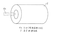
参考例2.
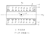
上述の参考例1では、オープン型の超電導磁石装置について説明したが、ここでは、ソレノイド型あるいは水平型と呼ばれる超電導磁石装置について説明する。図6は、ソレノイド型超電導磁石装置の外形を示す斜視図であり、図中矢印4bは、円筒状の真空遮断容器5(容器に相当する。)の、筒状開口部に、撮像時に被検者を挿入する方向を示している。図7は、ソレノイド型超電導磁石装置の断面図であり、略円筒状の真空遮断容器5には、その内部に低温容器6が配置され、その低温容器6内には、環状の超電導コイル51〜59(コイル群に相当。)が同軸となるように(Z軸に沿って。)、配列収納されている。この例では、円筒の両端部に配置された(同軸上において、コイル群の両端に位置する。)超電導コイル51、52は、その断面形状が略扇型であり、コイル群内で、同軸上における両端以外の位置に配置された超電導コイル53〜59は、その断面形状が略蒲鉾型である。
Reference Example 2
In the reference example 1 described above, the open type superconducting magnet device has been described. Here, a superconducting magnet device called a solenoid type or a horizontal type will be described. FIG. 6 is a perspective view showing the outer shape of the solenoid-type superconducting magnet device. In the figure, an arrow 4b indicates that a cylindrical opening of a cylindrical vacuum shut-off container 5 (corresponding to a container) is examined during imaging. The direction in which a person is inserted is shown. FIG. 7 is a cross-sectional view of a solenoid type superconducting magnet device. A cryogenic vessel 6 is disposed in a substantially cylindrical vacuum breaker vessel 5, and an annular superconducting coil 51-1 is placed in the cryogenic vessel 6. 59 (corresponding to the coil group) are arranged and accommodated so as to be coaxial (along the Z axis). In this example, the superconducting coils 51 and 52 disposed at both ends of the cylinder (coaxially located at both ends of the coil group) are substantially fan-shaped in cross section, and are coaxially arranged in the coil group. The superconducting coils 53 to 59 arranged at positions other than both ends in FIG.
この場合も、コイル形状の最適化において、磁界均一度および漏洩磁界の条件が厳しくなるにつれて、言い換えれば、なるべく少ない起磁力あるいは必要線材量で必要な条件を満足しようとするにつれて、コイルはなるべくR方向(円筒の軸をZ軸とすると、R方向とはZ=0(面)上の、Z軸から遠ざかる方向に相当する。)内側へ行きたがる、すなわちZ軸に向いたがるとともに、コイルのZ軸方向最大寸法、すなわち、コイル群の両端部に位置する超電導コイル51、52のコイル外側、開口端側に位置する部分は、なるべく外側へ行きたがる。
従って、最適化された超電導コイルは、真空断熱容器5の筒状開口部の内側面から遠ざかるにつれて、その巻回し幅が小さくなるように形成される。
Also in this case, in the optimization of the coil shape, as the conditions of the magnetic field uniformity and the leakage magnetic field become stricter, in other words, the coil becomes R as much as possible as it tries to satisfy the necessary condition with as little magnetomotive force or necessary wire amount as possible. Direction (when the axis of the cylinder is the Z-axis, the R direction corresponds to the direction on the Z = 0 (plane) and away from the Z-axis). The maximum dimension of the coil in the Z-axis direction, that is, the portion of the superconducting coils 51 and 52 located at both ends of the coil group, located on the coil outer side and the opening end side, wants to go as far as possible.
Therefore, the optimized superconducting coil is formed such that its winding width decreases as the distance from the inner surface of the cylindrical opening of the vacuum heat insulating container 5 increases.
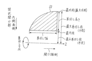
図8に超電導コイル52の断面形状拡大図を示すように、超電導磁石装置を構成する全ての超電導コイル51〜59(コイル群に相当する。)のうち、同軸上においてコイル群の両端に位置する超電導コイル51、52は、上記のような、筒状開口部の内側面から遠ざかるにつれて、その巻回し幅が小さくなるという特徴に加え、その巻回し高さが、筒状開口部の開口端に近づくにつれて大きくなるように形成され、その断面形状は略扇型となる。
As shown in the enlarged sectional view of the
また、コイル群のうち、同軸上における両端以外の位置に配置される超電導コイル53〜59は、図9に、超電導コイル53の断面形状拡大図を示すように、その巻回し高さが最大となる位置が、各コイルの、最も筒状開口部の内側面に近い側における巻回し幅の中間位置に相当し、そのコイルの断面形状が略蒲鉾型となるように形成される。
Further, in the coil group, the superconducting coils 53 to 59 arranged at positions other than both ends on the same axis have the maximum winding height as shown in the enlarged sectional view of the
次に、図10に、図7の超電導コイル52を囲む領域Bの拡大断面図を示し、その巻線の様子について説明する。参考例1と同様に、断面形状がコの字型の巻枠20に超電導線材21を巻き付けてコイルを形成するが、ここでは、巻き枠20内の片側に配置するスペーサ22bの幅が、層が増す毎に徐々に大きくなるように、1層目の巻回し幅よりも、2層目、3層目と層数が増えるにつれて、超電導線材21の巻回し幅が小さくなるように巻線作業を行い、最終的に断面形状が略扇型の超電導コイル52を得る。
Next, FIG. 10 shows an enlarged cross-sectional view of a region B surrounding the
また、断面形状が略蒲鉾型となる超電導コイル53〜59を得るには、巻枠20内の両側に配置する2つのスペーサの幅が同じになるように、かつ、層数が増す毎に徐々にスペーサ幅が大きくなるように調節し、層数が増す毎に、超電導線材21の巻回し幅が小さくなるように巻線作業を行うことで、最終的に、断面形状が中高の略蒲鉾型コイル53〜59が得られる。
このように、超電導磁石装置を構成する超電導コイル51〜59の断面形状が、最適化した略扇型または略蒲鉾型などの非矩形形状となるように、巻回し形成することで、効率上、最適な超電導コイルを実現でき、最適な超電導磁石装置が得られる。
Further, in order to obtain
Thus, by winding and forming so that the cross-sectional shape of the superconducting coils 51 to 59 constituting the superconducting magnet device is a non-rectangular shape such as an optimized substantially fan shape or substantially saddle shape, An optimum superconducting coil can be realized, and an optimum superconducting magnet device can be obtained.
参考例3.
先述の参考例1では、オープン型電磁石装置の超電導コイルを収納する容器(1a、1b。)の外形が円柱状であり、そのZ軸に沿う断面形状が図1に示すように矩形形状である例について述べたが、この参考例3では、オープン型の超電導磁石装置へ被検者を挿入する開口端をより開放的にするために、容器の対向面側の外周角部を削り取ったようなテーパー状とする例について説明する。
Reference Example 3.
In the reference example 1 described above, the outer shape of the container (1a, 1b) for housing the superconducting coil of the open type electromagnet device is cylindrical, and the cross-sectional shape along the Z-axis is rectangular as shown in FIG. Although an example has been described, in this reference example 3, in order to make the opening end into which the subject is inserted into the open superconducting magnet device more open, the outer peripheral corner on the opposite surface side of the container is scraped off. An example of a tapered shape will be described.
図11は、オープン型超電導磁石装置の断面図であり、この図において、上側、下側真空断熱容器31a、31bの対向面外周部はテーパー状となるように、それぞれ形成されている(テーパー部分を符号30で図示する。)。これにともなって、その対向面外周部に位置する超電導コイル10c、10dを、テーパー部分30の形状に沿うように、二つの容器の対向面から遠ざかるにつれて巻回し高さが大きくなるように、かつ容器の外周から軸(円柱状容器の軸に相当する。)に向かうにつれて巻回し幅が大きくなるように形成する。
また、上側、下側真空断熱容器31a、31bのテーパー部分30の形状に合わせて、低温容器32a、32bの形状もテーパーを反映させた形状とすることは言うまでもない。
FIG. 11 is a cross-sectional view of an open-type superconducting magnet device, in which the outer peripheral portions of the opposing surfaces of the upper and lower vacuum
Needless to say, the shape of the
図11の超電導コイル10dを含む領域Cの拡大断面図を図12に示し、その巻線の様子について説明する。この場合は、超電導コイル10c、10dの外形形状にテーパー形状を反映させるため、断面形状がコの字型の巻枠を用いることは不適当であり、図12に示すような、断面形状がL字型の巻枠20aを用いる。
巻線作業は、次のように行う。まず、巻枠20a内の底面(巻枠20a内の最内周面。)に絶縁層25および必要に応じて層間絶縁材23を巻き付け、その上に、二つのスペーサ22、22cを、それぞれ両側に配置する。スペーサ22は、巻枠20aの内側面(コイルの高さ方向に伸びる内側面。)に沿うように配置され、そこから1層目の超電導線材21を巻き付けるスペースを空けて、スペーサ22cを配置する。巻枠20aに沿っていない側に配置されるスペーサ22cは、テーパー形状30が反映される曲線的な面を持ち、その面は、コイルを巻き終わった段階でテーパー形状に沿うように、曲線的に加工された状態となる。
FIG. 12 shows an enlarged cross-sectional view of the region C including the
The winding work is performed as follows. First, the insulating
次に、1層目の二つのスペーサ22、22c間に超電導線材21を巻き付け、同様に、2層目、3層目と徐々に巻回し幅を小さくしつつ巻線作業を行い、巻き終わったら、テーパー形状を反映するように曲線的に加工した上部押さえ24aで、コイル表面を覆い、固定する。この段階で、超電導コイル10dは、巻枠20aと上部押さえ24aで囲まれた状態となる。コイル内に充填する熱硬化性の接着剤を用いる処理については、巻枠20aの形状にかかわらず、参考例1と同様であるので説明は省略する。
Next, the
このように、テーパー形状を反映させた外形の超電導コイル10dを形成し、下側真空断熱容器31bのテーパー部分30に位置する低温容器32b内部に配置することで、起磁力最小あるいは必要線材量最小などの条件を満たしつつ、オープン型超電導磁石装置の外形を広い間口の、開放性に優れた形状とすることができる。開放性に優れた超電導磁石装置を備えたMRI装置を得られることで、被検者の不快感や恐怖心を和らげることができる。
なお、二つの容器(31a、31b。)のうち、いずれか一方の対向面側外周部をテーパー形状とするだけでも、テーパー形状としない場合と比較して、より開放的な構造とできることは言うまでもない。
In this way, the
In addition, it cannot be overemphasized that it can be set as a more open structure compared with the case where it does not make a taper shape only by making one of the opposing surface side outer peripheral parts into a taper shape among two containers (31a, 31b.). Yes.
また、容器(31a、31b。)のテーパー部分30に配置するコイルの断面形状を、矩形ではなく略扇型に形成することで、矩形形状のコイルを配置する場合と比較すると、格段に起磁力が小さい、あるいは必要線材量の少ないコイルが実現でき、副次的に、コイルにかかる電磁力、コイル内の磁束密度などが軽減でき、支持構造体の簡素化、コスト低減、使用超電導線材の低コスト化などが実現できる。
Further, by forming the cross-sectional shape of the coil disposed in the tapered
参考例4.
次に、ソレノイド型超電導磁石装置の筒状開放部開口端をテーパー状に形成する場合について説明する。図13はソレノイド型超電導磁石装置の断面図であり、真空断熱容器(容器に相当する。)41を、その両端部において、開口部内側から開口端に向かうにつれて、筒状開口部の開口径が大きくなるようにテーパー状に形成する(テーパー部分40。)とともに、その両端部に位置する超電導コイル51a、52aを、テーパー部分40の形状に沿うように、真空断熱容器41の筒状開口部の内側面から遠ざかるにつれて、その巻回し幅が大きくなるように、かつ真空断熱容器41の最端部から開口部内側に向うにつれて、その巻回し高さが大きくなるように形成する。
Reference Example 4.
Next, a case where the cylindrical open portion opening end of the solenoid type superconducting magnet device is formed in a tapered shape will be described. FIG. 13 is a cross-sectional view of a solenoid type superconducting magnet device. The vacuum insulating container (corresponding to a container) 41 has an opening diameter of the cylindrical opening as it goes from the inside of the opening to the opening end at both ends thereof. The taper is formed so as to be large (tapered portion 40), and the
ここでは、円筒状の真空断熱容器41の両端に位置する超電導コイル51a、52aは、その断面が略矩形形状ではなく、テーパー形状を反映した、略扇型となるように形成される。図14に、図13の超電導コイル52aを囲む領域Dの拡大断面図を示す。参考例3のオープン型超電導磁石装置では、テーパー形状を反映した超電導コイル10dを形成する場合は、図12に示したような断面がL字型の巻枠20bを用いることを示したが、このソレノイド型超電導磁石装置を構成する超電導コイル51a、52aでは、テーパー面と巻回し方向との都合により、巻枠20bは、その断面形状が、テーパー形状を反映した曲線を有するレの字型に形成されたものを用いる。巻枠20bは、アルミニウムまたはステンレス等により形成され、断面形状が曲線となる部分については、あらかじめプレス加工によってテーパー部分40の形状を反映するように加工し、溶接によって直線の部分と繋ぎ合わせることで得られる。
Here, the
巻線作業では、まず、巻枠20b内に絶縁層25bを巻き付け(場合によっては、巻枠20bの曲線部分の内側全てに巻き付ける。)、さらに必要に応じて層間絶縁材23を配置し、その上に、1層目、2層目と順次超電導線材21を巻回して、断面形状が略扇型の超電導コイル52aを形成していく。この場合においても、参考例3と同様に、各層にスペーサ22、22dを配置し、そのスペーサ22、22d間の幅がコイル巻回し幅(巻幅。)となるように調整している。スペーサ22dは、テーパー部分40の形状を反映した巻枠20bの内側面に沿うように、あらかじめ一面が曲線的に加工されたものを用いる。
このように、テーパー形状40を反映させた超電導コイル51aを形成し、真空断熱容器41のテーパー部分40に位置する低温容器42内部に配置することで、参考例3と同様の効果を得ることができる。
In the winding work, first, the insulating layer 25b is wound around the winding frame 20b (in some cases, it is wound around the entire inside of the curved portion of the winding frame 20b), and the
Thus, by forming the
実施の形態1.
次に、この発明の実施の形態1について図15を参照して説明する。
一般的に、超電導コイルは、コイル内の最大磁束密度が大きくなるにつれて、クエンチ(常電導転移)のリスクが高くなるため、なるべくコイル内の最大磁束密度が小さくなるように設計するか、なるべく高い磁束密度に耐えうる超電導線材を使用する。言い換えれば、コイル内の最大磁束密度に耐えうる超電導線材が存在しなければ、MRI装置としての機能を有しないということになる。
例えば、超電導線材として比較的安価なNbTi(ニオブチタン)は、6T(テスラ)程度がほぼ限界であり、それ以上の磁束密度になると、例えばNb3Sn(ニオブ3スズ)などの超電導線材を使用せざるを得ない。しかし、現在Nb3SnはNbTiに比べて3〜5倍のコスト高となり、経済的ではない。
Embodiment 1 FIG.
Next, Embodiment 1 of the present invention will be described with reference to FIG.
In general, a superconducting coil has a higher risk of quenching (normal conduction transition) as the maximum magnetic flux density in the coil increases, so the maximum magnetic flux density in the coil should be designed to be as small as possible, or as high as possible. Use superconducting wire that can withstand the magnetic flux density. In other words, if there is no superconducting wire that can withstand the maximum magnetic flux density in the coil, it does not have a function as an MRI apparatus.
For example, NbTi (niobium titanium), which is relatively inexpensive as a superconducting wire, has a limit of about 6T (Tesla). When the magnetic flux density exceeds that, superconducting wire such as Nb3Sn (
一方、MRI装置は、さらなる高磁場化に加えて、更なるコンパクト化、開放性の向上が求められており、コイル内の最大磁束密度もそれに伴って大きくなってきているのが現状である。
このとき、各コイル内の磁束密度分布を見てみると、自己磁界によってコイル表面に近づくにつれて磁束密度が高くなる性質がある他、図15(a)にその断面図を示すように、複数のコイル70がある場合には、互いに影響を及ぼし合うことから、近接する二つのコイル70の最近接部分における磁束密度が高くなる傾向がわかる。高磁束密度となる部分は、断面形状が略矩形形状であるコイル70では、最近接部分となる角部70aに相当することが多い。
On the other hand, in addition to further increasing the magnetic field, the MRI apparatus is required to be further compact and improve the openness, and the maximum magnetic flux density in the coil is also increasing accordingly.
At this time, looking at the magnetic flux density distribution in each coil, there is a property that the magnetic flux density increases as it approaches the coil surface by the self-magnetic field, and as shown in a sectional view of FIG. In the case where the
一つのコイルは、なるべく1本(1種類)の超電導線で巻回すほうがよいため、使用する超電導線材は、最大磁束密度の値に耐えうるものを選択しなければならない。しかしながら、最大磁束密度となる角部70aは、一つのコイル内において一部の領域を占めるだけであり、それ以外の領域は、より低い磁束密度であるため、最大磁束密度に耐えうる超電導線材を用いることは、低い磁束密度の部分にとっては過剰性能になっているということができる。 Since it is better to wind one coil with one (one type) of superconducting wire as much as possible, the superconducting wire to be used must be selected to withstand the value of the maximum magnetic flux density. However, the corner portion 70a which becomes the maximum magnetic flux density occupies only a part of the region in one coil, and the other regions have a lower magnetic flux density. Therefore, a superconducting wire that can withstand the maximum magnetic flux density is used. The use can be said to be over-performing for low flux density parts.
そこで、図15(b)にコイルの断面図を示すように、近接する二つのコイル70の、最近接部分を削るように、角部70a(角に相当。)を落としたような断面形状となるように、巻回し形成した非矩形形状のコイル70bを採用することによって、断面が略矩形形状のコイル70を形成したときに、角部70aに発生していた磁束密度が大きな領域をなくし、コイル内の磁束密度をより低い値で均一化することができる。従って、使用する超電導線材の性能を抑え、安価にコイルを製作することが可能となる。
Therefore, as shown in a cross-sectional view of the coil in FIG. 15 (b), a cross-sectional shape with a corner 70a (corresponding to a corner) dropped so as to cut the closest part of two
図15(b)に示したような、断面が非矩形形状のコイル70bは、先述の参考例1〜4において示したような、断面形状が略扇型の超電導コイルを形成する場合と同じ要領で、その巻回し幅、巻回し高さを調節しつつ形成することができる。
The
その効果は、単に経済的に優れているというだけでなく、それによって生じた余裕分を高機能化(超電導磁石装置をコンパクト化すること、また、開放性に優れた外形とすることなど。)に転化することができるため、経済的かつ機能的な超電導コイルを同時に実現でき、この超電導コイルを超電導磁石装置や、他の技術に用いることができる。 The effect is not only economically superior, but also increases the function of the margin produced by it (such as making the superconducting magnet device more compact and making the outer shape more open). Therefore, an economical and functional superconducting coil can be realized at the same time, and this superconducting coil can be used for a superconducting magnet device and other technologies.
1a、31a 上側真空断熱容器
1b、31b 下側真空断熱容器
2a、2b、6、32a、32b、42 低温容器
3 連通管
4 磁界均一空間
4a、4b 矢印(被検者挿入方向)
5、41 真空断熱容器
10a、10b、10c、10d、11a、11b、12a、12b、13a、13b、51〜59 超電導コイル
20、20a、20b 巻枠
21 超電導線材
22、22a、22b、22c、22d スペーサ
23 層間絶縁材
24、24a、24b 上部押さえ
25、25b 絶縁層
30、40 テーパー部分
70 コイル(断面が略矩形形状)
70a 角部
70b コイル(断面が非矩形形状)。
1a, 31a Upper
5, 41
Claims (2)
Priority Applications (1)
| Application Number | Priority Date | Filing Date | Title |
|---|---|---|---|
| JP2007328998A JP4566232B2 (en) | 2007-12-20 | 2007-12-20 | Superconducting magnet device |
Applications Claiming Priority (1)
| Application Number | Priority Date | Filing Date | Title |
|---|---|---|---|
| JP2007328998A JP4566232B2 (en) | 2007-12-20 | 2007-12-20 | Superconducting magnet device |
Related Parent Applications (1)
| Application Number | Title | Priority Date | Filing Date |
|---|---|---|---|
| JP2003134861A Division JP4229752B2 (en) | 2003-05-13 | 2003-05-13 | Superconducting magnet device |
Publications (2)
| Publication Number | Publication Date |
|---|---|
| JP2008085376A JP2008085376A (en) | 2008-04-10 |
| JP4566232B2 true JP4566232B2 (en) | 2010-10-20 |
Family
ID=39355822
Family Applications (1)
| Application Number | Title | Priority Date | Filing Date |
|---|---|---|---|
| JP2007328998A Expired - Fee Related JP4566232B2 (en) | 2007-12-20 | 2007-12-20 | Superconducting magnet device |
Country Status (1)
| Country | Link |
|---|---|
| JP (1) | JP4566232B2 (en) |
Families Citing this family (1)
| Publication number | Priority date | Publication date | Assignee | Title |
|---|---|---|---|---|
| EP2568475A1 (en) * | 2011-09-10 | 2013-03-13 | Université Catholique De Louvain | Magnet and method for designing a magnet |
Citations (6)
| Publication number | Priority date | Publication date | Assignee | Title |
|---|---|---|---|---|
| JPH0196906A (en) * | 1987-09-28 | 1989-04-14 | Ga Technol Inc | Nuclear magnetic resonance image magnet system having a shleld and manufacture thereof |
| JPH065414A (en) * | 1992-06-22 | 1994-01-14 | Toshiba Corp | Superconducting magnet |
| JPH07508857A (en) * | 1992-04-15 | 1995-09-28 | ヒューストン・アドバンスト・リサーチ・センター | Structured coil electromagnet for magnetic resonance imaging |
| JPH08236341A (en) * | 1995-02-28 | 1996-09-13 | Hitachi Ltd | Hollow plate-like conductor laminated superconducting magnet |
| JPH08288122A (en) * | 1995-04-07 | 1996-11-01 | Oxford Magnet Technol Ltd | Improvement of mri magnet |
| JP2004275770A (en) * | 2003-03-14 | 2004-10-07 | Ge Medical Systems Global Technology Co Llc | Mri with pulsed readout magnet |
-
2007
- 2007-12-20 JP JP2007328998A patent/JP4566232B2/en not_active Expired - Fee Related
Patent Citations (6)
| Publication number | Priority date | Publication date | Assignee | Title |
|---|---|---|---|---|
| JPH0196906A (en) * | 1987-09-28 | 1989-04-14 | Ga Technol Inc | Nuclear magnetic resonance image magnet system having a shleld and manufacture thereof |
| JPH07508857A (en) * | 1992-04-15 | 1995-09-28 | ヒューストン・アドバンスト・リサーチ・センター | Structured coil electromagnet for magnetic resonance imaging |
| JPH065414A (en) * | 1992-06-22 | 1994-01-14 | Toshiba Corp | Superconducting magnet |
| JPH08236341A (en) * | 1995-02-28 | 1996-09-13 | Hitachi Ltd | Hollow plate-like conductor laminated superconducting magnet |
| JPH08288122A (en) * | 1995-04-07 | 1996-11-01 | Oxford Magnet Technol Ltd | Improvement of mri magnet |
| JP2004275770A (en) * | 2003-03-14 | 2004-10-07 | Ge Medical Systems Global Technology Co Llc | Mri with pulsed readout magnet |
Also Published As
| Publication number | Publication date |
|---|---|
| JP2008085376A (en) | 2008-04-10 |
Similar Documents
| Publication | Publication Date | Title |
|---|---|---|
| US9065306B2 (en) | Oxide superconducting coil, oxide-superconducting-coil assembly, and rotating machine | |
| CN102967835B (en) | For the spiral gradient coil of MR imaging apparatus | |
| JP4762225B2 (en) | Manufacturing method of superconducting magnet device | |
| JP6151706B2 (en) | Superconducting magnet apparatus and magnetic resonance imaging apparatus | |
| JP4566232B2 (en) | Superconducting magnet device | |
| JP4762226B2 (en) | Superconducting magnet device | |
| JP4229752B2 (en) | Superconducting magnet device | |
| JP4293341B2 (en) | Superconducting magnet device | |
| JP5295799B2 (en) | Gradient magnetic field coil, magnetic resonance imaging apparatus, and gradient magnetic field coil manufacturing method | |
| JP5224888B2 (en) | Superconducting magnet and magnet device including the same | |
| JP2010015821A (en) | Precursor for manufacturing nb3sn superconductive wire rod and method of manufacturing the same, and nb3sn superconductive wire rod | |
| JP4610449B2 (en) | Magnet device | |
| JP6138600B2 (en) | Magnetic field generator | |
| JP4703408B2 (en) | Superconducting magnet system | |
| JP5913288B2 (en) | Improved coil capable of generating a strong magnetic field and method of manufacturing the coil | |
| JP4767468B2 (en) | Shielded superconducting magnet joint | |
| JP2022133593A (en) | Superconducting electromagnet device and cooling method for superconducting electromagnet device | |
| JP6058319B2 (en) | Helical gradient coil for magnetic resonance imaging apparatus | |
| WO2015098588A1 (en) | Superconducting magnet apparatus | |
| JP6058577B2 (en) | High temperature superconducting wire and high temperature superconducting coil | |
| JP6001499B2 (en) | Magnetic resonance imaging system | |
| JP5448988B2 (en) | Superconducting magnet | |
| JP2011194136A (en) | Superconducting magnet device and magnetic resonance imaging apparatus | |
| JP2010200794A (en) | Magnetic resonance imaging apparatus | |
| JP2020078362A (en) | Superconducting magnet device or magnetic resonance imaging apparatus using the same |
Legal Events
| Date | Code | Title | Description |
|---|---|---|---|
| TRDD | Decision of grant or rejection written | ||
| A01 | Written decision to grant a patent or to grant a registration (utility model) |
Free format text: JAPANESE INTERMEDIATE CODE: A01 Effective date: 20100727 |
|
| A01 | Written decision to grant a patent or to grant a registration (utility model) |
Free format text: JAPANESE INTERMEDIATE CODE: A01 |
|
| A61 | First payment of annual fees (during grant procedure) |
Free format text: JAPANESE INTERMEDIATE CODE: A61 Effective date: 20100803 |
|
| FPAY | Renewal fee payment (event date is renewal date of database) |
Free format text: PAYMENT UNTIL: 20130813 Year of fee payment: 3 |
|
| R250 | Receipt of annual fees |
Free format text: JAPANESE INTERMEDIATE CODE: R250 |
|
| R250 | Receipt of annual fees |
Free format text: JAPANESE INTERMEDIATE CODE: R250 |
|
| LAPS | Cancellation because of no payment of annual fees |