JP4564089B2 - Method and apparatus for manufacturing polygonal paper tube - Google Patents
Method and apparatus for manufacturing polygonal paper tube Download PDFInfo
- Publication number
- JP4564089B2 JP4564089B2 JP2008511046A JP2008511046A JP4564089B2 JP 4564089 B2 JP4564089 B2 JP 4564089B2 JP 2008511046 A JP2008511046 A JP 2008511046A JP 2008511046 A JP2008511046 A JP 2008511046A JP 4564089 B2 JP4564089 B2 JP 4564089B2
- Authority
- JP
- Japan
- Prior art keywords
- core assembly
- core
- paper tube
- transfer
- paper
- Prior art date
- Legal status (The legal status is an assumption and is not a legal conclusion. Google has not performed a legal analysis and makes no representation as to the accuracy of the status listed.)
- Expired - Fee Related
Links
Images


Classifications
-
- B—PERFORMING OPERATIONS; TRANSPORTING
- B31—MAKING ARTICLES OF PAPER, CARDBOARD OR MATERIAL WORKED IN A MANNER ANALOGOUS TO PAPER; WORKING PAPER, CARDBOARD OR MATERIAL WORKED IN A MANNER ANALOGOUS TO PAPER
- B31C—MAKING WOUND ARTICLES, e.g. WOUND TUBES, OF PAPER, CARDBOARD OR MATERIAL WORKED IN A MANNER ANALOGOUS TO PAPER
- B31C3/00—Making tubes or pipes by feeding obliquely to the winding mandrel centre line
-
- Y—GENERAL TAGGING OF NEW TECHNOLOGICAL DEVELOPMENTS; GENERAL TAGGING OF CROSS-SECTIONAL TECHNOLOGIES SPANNING OVER SEVERAL SECTIONS OF THE IPC; TECHNICAL SUBJECTS COVERED BY FORMER USPC CROSS-REFERENCE ART COLLECTIONS [XRACs] AND DIGESTS
- Y10—TECHNICAL SUBJECTS COVERED BY FORMER USPC
- Y10T—TECHNICAL SUBJECTS COVERED BY FORMER US CLASSIFICATION
- Y10T428/00—Stock material or miscellaneous articles
- Y10T428/13—Hollow or container type article [e.g., tube, vase, etc.]
- Y10T428/1303—Paper containing [e.g., paperboard, cardboard, fiberboard, etc.]
Description
本発明は大韓民国特許出願第10−2005−0039872号(出願日2005年5月12日)の優先権主張出願である。 The present invention is a priority application of Korean Patent Application No. 10-2005-0039872 (filing date: May 12, 2005).
本発明は多角形紙管の製造方法及び装置に係り、より詳しくは回転するコアに螺旋状に重畳して巻き付けられた複数の紙ストリップを、コアの内部で移動する部材を利用して、コアから排出することで、より厚肉の紙管を製造することができる方法及び装置に関するものである。また、本発明は、前記の方法によって製造された断面多角形の紙管に関するものである。 The present invention relates to a method and apparatus for manufacturing a polygonal paper tube. More specifically, the present invention relates to a core using a member that moves a plurality of paper strips wound in a spiral manner on a rotating core. It is related with the method and apparatus which can manufacture a thicker paper tube by discharging | emitting from. The present invention also relates to a paper tube having a polygonal cross section manufactured by the above method.
[従来技術の文献情報]
国際出願公開第WO97/13695号、1997年4月17日公開、METHOD AND DEVICE FOR PRODUCTION
OF TUBES
大韓民国公開特許公報第2002−0038467号、2002年5月23日公開、多角紙管の製造装置
アメリカ合衆国特許第4120523号、1978年10月17日公開、POLYGONALLY WRAPPED SLEEVE
AND METHODS AND DEVICES FOR MAKING SAME
日本国特開昭50−91808号、1975年7月22日公開、角形紙管の製造方法
[Document information of prior art]
International Application Publication No. WO 97/13695, published April 17, 1997, METHOD AND DEVICE FOR PRODUCTION
OF TUBES
Korean Published Patent Publication No. 2002-0038467, published on May 23, 2002, Polygonal paper tube manufacturing apparatus United States Patent No. 4120523, published on October 17, 1978, POLYGONALLY WRAPED SLEEVE
AND METHODS AND DEVICES FOR MAKING SAME
Japanese Laid-Open Patent Publication No. Sho 50-91808, published on July 22, 1975, manufacturing method of rectangular paper tube
最近、従来に利用された木材や合成樹脂で製造されたパレットの代わりに、紙で製造されたパレットが開発され、貨物の運送に利用されている。通常、紙パレットは、貨物が載せられる上板と、前記上板の下面に付着され上板を支持する支持部材とから構成される。紙パレットの支持部材としては、四角断面を有する紙管が多く使用される。 Recently, paper-made pallets have been developed instead of pallets made of wood or synthetic resin, which have been used in the past, and are used to transport cargo. Usually, a paper pallet is composed of an upper plate on which cargo is placed and a support member that is attached to the lower surface of the upper plate and supports the upper plate. A paper tube having a square cross section is often used as a support member for the paper pallet.
従来に知られた四角断面を有する紙管の製造方法及び装置は、下記の特許文献等を含み、多くの文献に公開されている。国際出願公開第WO97/13695号、大韓民国公開特許公報公開第2002−0038467号、及び日本特開昭50−91808号に公開された四角紙管の製造方法や装置はいずれも同一原理を利用した方法及び装置である。前記特許文献に公開された角形紙管の製造装置は、回転する断面四角形のコアに、予め接着剤が塗布された複数の紙ストリップを供給して、コアの外周面に巻き付ける。また、従来の装置は、コアと同一角速度でコアの回転軸を中心に回転する複数のローラを備えており、また、前記複数のローラは、コアの外周面に巻き付けられたストリップを加圧しながらコアの長手方向に同時に回転することになっている(コアの長手方向に垂直である回転軸を中心に回転するようになっている)。すなわち、従来の角形紙管の製造装置は、前記複数のローラが、コアに巻き付けられた紙ストリップ(紙管)を加圧しながらコアの長手方向に回転するとき、ローラと紙管外側面との間に発生する摩擦力がコアと紙管の内側面との間に発生する摩擦力より大きい場合、コアに巻き付けられた紙管がコアから分離され、コアの長手方向に排出される原理を利用したものである。 Conventionally known methods and apparatuses for manufacturing a paper tube having a square cross section include the following patent documents and the like, and are published in many documents. The rectangular paper tube manufacturing method and apparatus disclosed in International Application Publication No. WO 97/13695, Republic of Korea Publication Patent Publication No. 2002-0038467 and Japanese Patent Application Laid-Open No. 50-91808 are all methods using the same principle. And device. The rectangular paper tube manufacturing apparatus disclosed in the patent document supplies a plurality of paper strips coated with an adhesive in advance to a rotating core having a quadrangular cross section and winds the core around the outer peripheral surface of the core. In addition, the conventional apparatus includes a plurality of rollers that rotate around the rotation axis of the core at the same angular velocity as the core, and the plurality of rollers pressurize the strip wound around the outer peripheral surface of the core. It is supposed to rotate at the same time in the longitudinal direction of the core (it is designed to rotate around a rotation axis perpendicular to the longitudinal direction of the core). That is, in the conventional square paper tube manufacturing apparatus, when the plurality of rollers rotate in the longitudinal direction of the core while pressing a paper strip (paper tube) wound around the core, the roller and the outer surface of the paper tube Uses the principle that the paper tube wound around the core is separated from the core and discharged in the longitudinal direction of the core when the friction force generated between them is larger than the friction force generated between the core and the inner surface of the paper tube It is a thing.
一方、アメリカ合衆国特許第4120523号に開示された四角紙管の製造方法は、連続的に成形されて排出される円形の紙管を複数の成形ローラで四角形になるように順次成形して製造する方法である。 On the other hand, in the method for manufacturing a square paper tube disclosed in US Pat. No. 4,120,523, a circular paper tube that is continuously formed and discharged is sequentially formed into a square shape by a plurality of forming rollers. It is.
前述した文献に公開された四角紙管の製造方法及び装置は、いずれも一定厚さ以上の角形紙管、例えば5mm以上の厚さを有する断面四角形の紙管を螺旋状に重畳して巻き付けて連続的に製造することが難しい。 The method and apparatus for manufacturing a square paper tube disclosed in the above-mentioned literatures all involve winding a rectangular paper tube having a certain thickness or more, for example, a paper tube having a square cross section having a thickness of 5 mm or more in a spiral manner. Difficult to produce continuously.
第1方法、すなわち回転する角形のコアに複数の紙ストリップを巻き付け、この巻き付けられた外周面を複数のローラで加圧しながらコアから紙管を分離して角形紙管を製造する方法は、紙管の厚さが厚いほど、ローラと紙管間の摩擦力を大きくするために、ローラーの加圧力を大きくしなければならないが、ローラーの加圧力を大きくすればするほど、コアと紙管内部面間の摩擦力が大きくなり、コアから紙管の分離がさらに難しくなるという問題点がある。第2方法、すなわち円形の紙管を成形して四角形の紙管を製造する方法は、円周長さと四角周長さが正確に一致することができないから、理論的に正確な形状の四角形を作ることができなく、紙管の厚さが一定の厚さ以上になれば、内側に巻き付けられたストリップと外側に巻き付けられたストリップとの間に隙間が増加し、成形の際に形状が歪む問題点がある。 A first method, that is, a method of manufacturing a rectangular paper tube by winding a plurality of paper strips around a rotating rectangular core and separating the paper tube from the core while pressing the wound outer peripheral surface with a plurality of rollers, The thicker the tube, the greater the force applied to the roller to increase the frictional force between the roller and the paper tube, but the greater the roller pressure, the more the core and paper tube There is a problem in that the frictional force between the surfaces increases and it becomes more difficult to separate the paper tube from the core. The second method, that is, the method of manufacturing a circular paper tube by forming a circular paper tube cannot accurately match the circumferential length and the square circumferential length. If it cannot be made and the thickness of the paper tube exceeds a certain thickness, the gap increases between the strip wound inside and the strip wound outside, and the shape is distorted during molding. There is a problem.
また、従来の角形紙管の製造装置は、材料を節減するために、段ボールストリップで角形紙管を製造しようとする場合、段ボールの皺部が損傷するため、段ボールストリップを利用した角形紙管を製造することができない欠点があった。 In addition, in the conventional square paper tube manufacturing apparatus, when a square paper tube is manufactured with a corrugated cardboard strip in order to save the material, the corrugated cardboard strip is damaged. There were drawbacks that could not be produced.
本発明は、前記のような従来の角形紙管の製造方法及び装置が持っている問題点を解決するためのものである。すなわち、本発明の目的は、コアに螺旋状にストリップを重畳して巻き付けることにより、連続的な紙管の生産が可能であり、生産性が高く、同時に厚肉の高強度角形紙管を生産する方法及び装置を提供することである。また、本発明は、段ボールストリップを利用して角形紙管を製造する方法及び装置を提供することを他の目的とする。 The present invention is to solve the problems of the above-described conventional square paper tube manufacturing method and apparatus. That is, the object of the present invention is to produce a continuous paper tube by winding a strip in a spiral shape around the core, which is highly productive and at the same time produces a thick, high-strength rectangular paper tube. It is an object to provide a method and apparatus. Another object of the present invention is to provide a method and an apparatus for manufacturing a square paper tube using a cardboard strip.
また、本発明のさらに他の目的は、本発明の方法によって生産された強度の優れた角形紙管を提供することである。 Still another object of the present invention is to provide a square paper tube with excellent strength produced by the method of the present invention.
本発明の一側面では、断面多角形の紙管の製造方法が提供される。本発明による断面多角形の紙管の製造方法は、最下層のストリップ以外に予め接着剤が塗布された複数の紙ストリップを多角形断面の回転するコアの外周面に螺旋状に重畳して巻き付ける巻き付け工程と、少なくとも一部がストリップが巻き付けられる前記コアの外周面から連続的に露出してコアの長手方向に移動するようにコアの内部に設置された移送部材を、コアの外周面に巻き付けられた前記最下層のストリップの内面に接触させることにより、コアに巻き付けられた複数のストリップを長手方向に連続的に移送する移送工程と、を含むことを特徴とする。 In one aspect of the present invention, a method of manufacturing a paper tube having a polygonal cross section is provided. In the method for manufacturing a polygonal cross section paper tube according to the present invention, a plurality of paper strips previously coated with an adhesive in addition to the lowermost layer strip are spirally superimposed on the outer peripheral surface of a rotating core having a polygonal cross section. A winding member, and a transfer member installed at the inside of the core so as to move continuously in the longitudinal direction of the core while being continuously exposed from the outer peripheral surface of the core, at least a part of which is wound with the strip, is wound around the outer peripheral surface of the core A transfer step of continuously transferring a plurality of strips wound around the core in the longitudinal direction by contacting the inner surface of the lowermost strip.
本発明による紙管の製造方法は、従来の角形紙管製造方法とは異なり、コアに巻き付けられて形成された紙管の外側面を加圧して、コアから紙管を分離させるものではなく、コアに巻き付けられて形成された紙管の内側面と接触する移送部材をコアの自由端側に連続的に移動させることにより、螺旋状に重畳してコアに巻き付けられる紙管を連続的にコアから分離する点で独創的な方法である。 Unlike the conventional square paper tube manufacturing method, the paper tube manufacturing method according to the present invention does not separate the paper tube from the core by pressurizing the outer surface of the paper tube wound around the core, By continuously moving the transfer member that contacts the inner surface of the paper tube that is wound around the core to the free end side of the core, the paper tube that is wound around the core in a spiral manner is continuously cored. It is an ingenious method in that it separates from.
また、コアから紙管の分離をより容易にするために、本発明による紙管の製造方法において、前記移送工程は、前記コアと同一角速度で回転するフレームに設置された加圧手段で、巻き付けられた複数のストリップにおける、前記移送手段が接触する位置の上面を同時に加圧しながら行うことが好ましい。本発明の方法に使用される移送部材としては、移送ベルト、移送ギア、移送スクリューを使用することができ、コアの外周面から一部が露出して長手方向に移動するようにコアの内部に設置される。 In addition, in order to further facilitate separation of the paper tube from the core, in the paper tube manufacturing method according to the present invention, the transfer step is wound by a pressurizing means installed on a frame rotating at the same angular velocity as the core. In the plurality of strips formed, it is preferable that the upper surface of the position where the transfer means contacts is simultaneously pressed. As the transfer member used in the method of the present invention, a transfer belt, a transfer gear, or a transfer screw can be used, and a part of the outer peripheral surface of the core is exposed and moved in the longitudinal direction so as to move in the longitudinal direction. Installed.
本発明の他の側面では、断面多角形の紙管の製造装置が提供される。本発明による断面多角形の紙管の製造装置は、フレームと、最下層のストリップ以外に予め接着剤が塗布された複数の紙ストリップが外周面に螺旋状に重畳して巻き付けられるように、一端が前記フレームに回転可能に支持され、他端は自由端とされ、外周面が所定の多角形を有する細長型コア組立体と、前記コア組立体を回転させるための動力を提供する第1駆動手段と、前記第1駆動手段の動力を受けて前記コア組立体に伝達する第1伝動手段と、少なくとも一部がストリップが巻き付けられた前記コア組立体の外周面から露出するように前記コア組立体に設置される部材であって、動力を受けて、前記部材の露出する部分が前記コア組立体の自由端側に移動するように設けられ、前記コア組立体の外周面に巻き付けられる複数のストリップのうち、前記最下層のストリップの内面に、連続的に露出する前記部分が接触して、コア組立体に巻き付けられる複数のストリップを連続的にコア組立体の自由端側に移送させる移送部材と、前記移送部材の前記部分をコア組立体の外周面から連続的に露出させるための動力を提供する第2駆動手段と、前記第2駆動手段の動力を受けて前記移送部材に伝達する第2伝動手段とを含むことを特徴とする。 In another aspect of the present invention, an apparatus for manufacturing a paper tube having a polygonal cross section is provided. The apparatus for manufacturing a polygonal cross-section paper tube according to the present invention has one end so that a plurality of paper strips coated with an adhesive in addition to the frame and the lowermost layer strip are spirally wound around the outer peripheral surface. Is rotatably supported by the frame, the other end is a free end, and an outer peripheral surface having a predetermined polygonal shape, and a first drive that provides power for rotating the core assembly Means, first transmission means that receives power from the first drive means and transmits the power to the core assembly, and the core assembly so that at least a part thereof is exposed from the outer peripheral surface of the core assembly around which the strip is wound. It is a member installed in a three-dimensional structure, and is provided with power so that an exposed portion of the member moves to a free end side of the core assembly, and is wound around an outer peripheral surface of the core assembly. Stri A transfer member for continuously transferring a plurality of strips wound around the core assembly to the free end side of the core assembly by contacting the continuously exposed portion with the inner surface of the lowermost layer strip A second drive means for providing power for continuously exposing the portion of the transfer member from the outer peripheral surface of the core assembly; and a second drive means for receiving the power of the second drive means and transmitting the power to the transfer member. And 2 transmission means.
本発明によれば、前記コア組立体に設置された移送部材が、コア組立体が回転するにしたがって外周面に螺旋状に巻き付けられる複数の紙ストリップのうち、最下層の紙ストリップをコア組立体の自由端側に移送させる。本発明による角形紙管の製造装置は、巻き付けられた紙管の外周面をローラーで加圧して、コアから紙管の内周面がスライドして排出されるようにする従来の角形紙管の製造装置とは異なり、移送部材が巻き付けられた角形紙管の内周面と接触して、コアの自由端側に押し出して排出させるようになっているので、コアと角形紙管間の摩擦力が小さくなり、より厚肉の紙管を製造することができることになる。すなわち、コア組立体の外周面から連続的に露出する移送部材の部分が最下層の紙ストリップの内面と接触することによって発生する摩擦力によって、コア組立体の外周面に巻き付けられた複数の紙ストリップ紙管をコア組立体の自由端側に排出させることで、紙管を製造できるようになる。 According to the present invention, the transfer member installed in the core assembly includes the lowermost paper strip among the plurality of paper strips spirally wound around the outer peripheral surface as the core assembly rotates. It is moved to the free end side. An apparatus for manufacturing a square paper tube according to the present invention is a conventional square paper tube which presses the outer peripheral surface of a wound paper tube with a roller so that the inner peripheral surface of the paper tube slides and is discharged from the core. Unlike the manufacturing equipment, it contacts the inner peripheral surface of the rectangular paper tube around which the transfer member is wound, and is pushed out to the free end side of the core to be discharged, so the frictional force between the core and the rectangular paper tube Becomes smaller, and a thicker paper tube can be manufactured. That is, a plurality of papers wound around the outer peripheral surface of the core assembly by the frictional force generated by the portion of the transfer member continuously exposed from the outer peripheral surface of the core assembly coming into contact with the inner surface of the lowermost paper strip. The paper tube can be manufactured by discharging the strip paper tube to the free end side of the core assembly.
また、本発明による紙管を製造する装置は、片面段ボールストリップを使用して角形紙管を製造することができる利点がある。従来の角形紙管の製造装置は、コアに巻き付けられた紙ストリップの外周面を加圧するようになっているから、角形紙管の製造の際に、片面段ボールストリップを使用すれば、段ボールストリップの皺部(波型に形成された部分)が損傷するため、段ボールストリップを使用することができない。しかし、本発明による角形紙管の製造装置は、コア組立体の内部に設置され、コア組立体の外周面から連続的に露出する移送部材の部分が、コア組立体に巻き付けられた段ボールストリップと接触して、巻き付けられた紙管をコア組立体の自由端側に押し出すことで、コア組立体から排出させるようになっているので、段ボールストリップの皺部が損傷しない。 In addition, the apparatus for manufacturing a paper tube according to the present invention has an advantage that a square paper tube can be manufactured using a single-sided cardboard strip. Since the conventional square paper tube manufacturing apparatus pressurizes the outer peripheral surface of the paper strip wound around the core, if a single-sided cardboard strip is used when manufacturing the square paper tube, Corrugated cardboard strips cannot be used due to damage to the buttocks (corrugated part). However, the square paper tube manufacturing apparatus according to the present invention includes a corrugated cardboard strip that is installed inside the core assembly, and the portion of the transfer member that is continuously exposed from the outer peripheral surface of the core assembly is wound around the core assembly. By contacting and pushing out the wound paper tube to the free end side of the core assembly, the corrugated portion of the cardboard strip is not damaged.
また、本発明による断面多角形の紙管の製造装置において、前記第1伝動手段は、前記第1駆動手段から動力を受けて回転するように前記フレームに回転可能に支持され、長手方向に貫通孔が形成された中空の第1回転軸と、一側が前記第1回転軸に連結され、他側が前記コア組立体に連結されたカップリング部材とを含み、前記第2伝動手段は、前記第2駆動手段から動力を受けて回転するように、前記第1回転軸の貫通孔に挿入され、回転可能に第1回転軸に支持された第2回転軸と、前記第2回転軸の回転動力を前記移送部材に伝達するための第3伝動手段とを含むことを特徴とする。すなわち、コア組立体を回転させるための駆動手段(モーター)の動力を伝達するための第1回転軸を中空にし、移送手段を駆動するための駆動手段(サーボモーター)の動力を伝達するための第2回転軸を前記第1回転軸の中空に回転可能に設置して、紙管の製造装置の大きさを減らし、安定的な動力伝達を可能にする。 Also, in the paper tube manufacturing apparatus having a polygonal cross section according to the present invention, the first transmission means is rotatably supported by the frame so as to rotate by receiving power from the first driving means, and penetrates in the longitudinal direction. A hollow first rotating shaft having a hole formed therein; a coupling member having one side connected to the first rotating shaft and the other side connected to the core assembly; and the second transmission means includes the first rotating shaft A second rotating shaft that is inserted into the through-hole of the first rotating shaft and is rotatably supported by the first rotating shaft so as to rotate by receiving power from the two driving means; and the rotating power of the second rotating shaft And a third transmission means for transmitting to the transfer member. That is, the first rotating shaft for transmitting the power of the driving means (motor) for rotating the core assembly is made hollow, and the power of the driving means (servo motor) for driving the transfer means is transmitted. The second rotating shaft is rotatably installed in the hollow of the first rotating shaft to reduce the size of the paper tube manufacturing apparatus and enable stable power transmission.
また、本発明による断面多角形の紙管の製造装置において、前記移送部材は、移送ベルトを使用するか、移送ギアを使用するか、移送スクリューを使用することができる。移送ベルトを移送部材として使用する場合、一対の移送ベルトをそれぞれコア組立体の対向する外周面から長手方向に一部が露出するように設置し、露出した一部がコア組立体の自由端側に移動するように設置する。また、前記第3伝動手段は、前記第2回転軸に対して直角に前記カップリング部材に回転可能に設置された第3回転軸と、前記第2回転軸の動力を前記第3回転軸に伝達するために、第2及び第3回転軸にそれぞれ設置されてかみ合う一対の傘歯車と、前記第3回転軸の回転動力を前記一対の移送ベルトに伝達するための第4伝動手段とをさらに含む。 In the paper tube manufacturing apparatus according to the present invention, the transfer member may use a transfer belt, a transfer gear, or a transfer screw. When using a transfer belt as a transfer member, each of the pair of transfer belts is installed so that a part is exposed in the longitudinal direction from the opposing outer peripheral surface of the core assembly, and the exposed part is the free end side of the core assembly. Install to move to. The third transmission means includes a third rotating shaft rotatably installed on the coupling member at a right angle to the second rotating shaft, and the power of the second rotating shaft is used as the third rotating shaft. A pair of bevel gears installed on and engaged with the second and third rotating shafts respectively for transmission, and a fourth transmission means for transmitting the rotational power of the third rotating shafts to the pair of transfer belts; Including.
移送ベルトを移送部材として使用する場合、コア組立体の四角棒コアに移送ベルトの移動を案内するための一対の移送案内部材を固定して剛性を大きくするか、上部及び下部コアに移送ベルトを設置し、上部及び下部コアの間隔を調節することにより、製造される紙管の幅を容易に変更することができる。 When a transfer belt is used as a transfer member, a pair of transfer guide members for guiding the movement of the transfer belt is fixed to the rectangular core of the core assembly to increase rigidity, or the transfer belt is attached to the upper and lower cores. The width of the manufactured paper tube can be easily changed by installing and adjusting the distance between the upper and lower cores.
単一の四角棒コアと移送案内部材を使用してコア組立体を構成する場合、前記コア組立体は、一端が前記カップリング部材に固定される長い四角棒コアと、前記四角棒コアの対向する両側面に固定された一対の長い移送案内部材とを含み、前記それぞれの移送案内部材は四角棒コアの幅より大きな幅を有し、四角棒部材の両側面に固定されたベース部と、前記ベース部の幅方向の両端から一定距離だけ離隔して対向するベース部側に平行に突出し、長手方向に一定長さだけ伸びた上側及び下側案内羽部とを備え、前記一対の移送ベルトは、前記一対の移送案内部材の対向する上側及び下側案内羽部にそれぞれかけられて設置され、前記第4伝動手段は、前記コア組立体の四角棒コアの固定端側に回転可能に設置され、上部移送ベルトがかけられた上部ベルト駆動軸及び下部移送ベルトがかけられた下部ベルト駆動軸と、コア組立体の移送案内部材の自由端に一定距離だけ離隔して回転可能にそれぞれ固定され、上部移送ベルトがかけられた上部アイドルローラー及び下部移送ベルトがかけられた下部アイドルローラーと、前記上部及び下部ベルト駆動軸にそれぞれ前記第3回転軸の回転動力を伝達するためのギアとを含むことを特徴とする。 When a core assembly is configured using a single square bar core and a transfer guide member, the core assembly includes a long square bar core, one end of which is fixed to the coupling member, and an opposite of the square bar core. A pair of long transfer guide members fixed to both side surfaces, each of the transfer guide members having a width larger than the width of the square bar core, and a base portion fixed to both side surfaces of the square bar member; A pair of transfer belts, comprising upper and lower guide blades projecting in parallel to opposite base portions spaced apart from each other in the width direction of the base portion by a certain distance and extending in the longitudinal direction by a certain length; Are installed on the upper and lower guide blades facing each other of the pair of transfer guide members, and the fourth transmission means is rotatably installed on the fixed end side of the square bar core of the core assembly. And the upper transfer belt is broken The upper belt drive shaft and the lower belt drive shaft on which the lower transfer belt is hung are fixed to the free end of the transfer guide member of the core assembly so as to be rotatable by a predetermined distance, and the upper transfer belt is hung. And a lower idle roller on which an upper idle roller and a lower transfer belt are hung, and a gear for transmitting rotational power of the third rotary shaft to the upper and lower belt drive shafts, respectively.
上部コアと下部コアを使用してコア組立体を構成する場合、前記コア組立体は、前記カップリング部材に一端が固定された長い上部コアと、前記上部コアから一定距離だけ離隔して前記カップリング部材に一端が固定された長い下部コアを含み、前記一対の移送ベルトは、それぞれ上部及び下部コアを長手方向に取り囲むように設置されており、前記第4伝動手段は、前記上部及び下部コアのそれぞれの固定端側に回転可能に設置され、上部移送ベルトがかけられた上部ベルト駆動軸及び下部移送ベルトがかけられた下部ベルト駆動軸と、前記上部及び下部コアのそれぞれの自由端に回転可能に設置され、上部移送ベルトがかけられた上部アイドルローラー及び下部移送ベルトがかけられた下部アイドルローラーと、前記上部及び下部ベルト駆動軸にそれぞれ前記第3回転軸の回転動力を伝達するための伝動手段とを含むことを特徴とする。 When a core assembly is configured using an upper core and a lower core, the core assembly includes a long upper core having one end fixed to the coupling member, and a cup spaced apart from the upper core by a certain distance. The ring member includes a long lower core having one end fixed to the ring member, and the pair of transfer belts are installed so as to surround the upper and lower cores in the longitudinal direction, respectively, and the fourth transmission means includes the upper and lower cores. The upper belt drive shaft on which the upper transfer belt is hung, the lower belt drive shaft on which the lower transfer belt is hung, and the respective free ends of the upper and lower cores are rotatably installed on the fixed end sides of the upper and lower cores. An upper idler roller with an upper transfer belt and a lower idler roller with a lower transfer belt installed thereon, and the upper and lower belts Characterized in that it comprises a transmission means for transmitting the rotational power of each of the third rotating shaft to shaft.
移送ギアを移送部材として使用する場合、少なくとも一対の移送ギアをコア組立体の長手方向に対して垂直に設置された回転軸を中心に回転するように設置するとともにコア組立体の外周面の対向部から一部が露出するように設置する。また、前記第3伝動手段は、前記第2回転軸に対して直角に前記カップリング部材に回転可能に設置された第3回転軸と、前記第2回転軸の動力を前記第3回転軸に伝達するために、第2及び第3回転軸にそれぞれ設置されてかみ合う一対の傘歯車と、前記第3回転軸の回転動力を前記一対の移送ギアに伝達するための第5伝動手段とをさらに含む。 When a transfer gear is used as a transfer member, at least a pair of transfer gears are installed so as to rotate around a rotation shaft installed perpendicular to the longitudinal direction of the core assembly and face the outer peripheral surface of the core assembly. Install so that a part is exposed from the part. The third transmission means includes a third rotating shaft rotatably installed on the coupling member at a right angle to the second rotating shaft, and the power of the second rotating shaft is used as the third rotating shaft. A pair of bevel gears installed on and engaged with the second and third rotating shafts respectively for transmission, and fifth transmission means for transmitting the rotational power of the third rotating shafts to the pair of transfer gears; Including.
移送スクリューを移送部材として使用する場合、前記コア組立体の外周面から長手方向に一部が露出するように複数の移送スクリューのそれぞれの一端を前記カップリング部材に回転可能に設置し、他端を前記コア組立体に回転可能に固定設置する。また、前記第3伝動手段は、前記第2回転軸に設置された駆動ギアと、前記駆動ギアとかみ合うように、前記それぞれの移送スクリューの一端に固定設置された複数の従動ギアとを含む。 When using a transfer screw as a transfer member, one end of each of the plurality of transfer screws is rotatably installed on the coupling member such that a part of the core assembly is exposed in the longitudinal direction from the outer peripheral surface of the core assembly. Is fixed to the core assembly so as to be rotatable. The third transmission means includes a drive gear installed on the second rotating shaft and a plurality of driven gears fixedly installed at one ends of the respective transfer screws so as to mesh with the drive gear.
また、本発明に他の断面多角形の紙管の製造装置は、コア組立体の自由端が搖れることを防止して装置を安全に運転し、コア組立体の自由端にスリップなしに紙管を排出するとともに、排出される紙管の多角形を維持するための手段をさらに含む。前記の目的を達成するために、本発明による断面多角形の紙管の製造装置は、前記フレームに支持され、コア組立体と同一角速度で回転するように設置され、前記コア組立体の自由端側に排出される複数のストリップの巻き付けられた紙管が通過するための貫通孔が形成された中空の第4回転軸と、前記中空の第4回転軸に固定され、前記コア組立体の自由端に巻き付けられた複数のストリップのうち、最上層ストリップの上面を対称的に加圧するための加圧手段とをさらに含む。前記加圧手段は、一定圧力で紙管を加圧するように、弾性部材によって支持されることが好ましい。 Further, according to another aspect of the present invention, there is provided a paper tube manufacturing apparatus having a polygonal cross-section, which prevents the free end of the core assembly from being twisted, operates the apparatus safely, and does not slip on the free end of the core assembly. Means are further included for discharging the tube and maintaining the polygon of the discharged paper tube. To achieve the above object, a paper tube manufacturing apparatus having a polygonal cross section according to the present invention is supported by the frame and installed to rotate at the same angular velocity as the core assembly, and the free end of the core assembly. A hollow fourth rotating shaft formed with a through-hole through which a paper tube wound with a plurality of strips discharged to the side passes, and the core assembly is freely fixed to the hollow fourth rotating shaft. Pressure means for symmetrically pressing the upper surface of the uppermost layer strip among the plurality of strips wound around the end is further included. The pressurizing means is preferably supported by an elastic member so as to pressurize the paper tube at a constant pressure.
また、本発明による断面多角形の紙管の製造装置は、コア組立体の自由端に連続的に製造されて排出される紙管を適当な長さに切断するための紙管カッティング手段をさらに備えている。紙管カッティング手段は、前記コア組立体の長手方向に移動可能に前記フレームに設置されたベースと、前記コア組立体の長手方向に対して垂直方向に移動可能に前記ベースに設置されたカッターとを含む。前記カッターは、回転する円形の刃または鋸の刃を使用することが好ましい。また、紙管カッティング手段は、前記ベースに支持され、前記コア組立体と同一角速度で回転するように設置され、前記コア組立体の自由端側に排出される複数のストリップの巻き付けられた紙管が通過するための貫通孔が形成された中空の第4回転軸をさらに含むことが好ましい。 The apparatus for manufacturing a paper tube having a polygonal cross section according to the present invention further comprises a paper tube cutting means for cutting the paper tube continuously manufactured and discharged at the free end of the core assembly into an appropriate length. I have. The paper tube cutting means includes a base installed on the frame so as to be movable in the longitudinal direction of the core assembly, and a cutter installed on the base so as to be movable in a direction perpendicular to the longitudinal direction of the core assembly. including. The cutter is preferably a rotating circular blade or a saw blade. The paper tube cutting means is supported by the base, is installed so as to rotate at the same angular velocity as the core assembly, and is a paper tube around which a plurality of strips are discharged to the free end side of the core assembly. It is preferable to further include a hollow fourth rotating shaft in which a through-hole for passing through is formed.
本発明のさらに他の側面によれば、本発明による断面多角形の紙管の製造方法によって製造された紙管を提供する。特に、本発明の方法によって製造された紙管において、紙管を製造するために使用される複数の紙ストリップは少なくとも一つの片面段ボールストリップを含むことを特徴とする。 According to still another aspect of the present invention, there is provided a paper tube manufactured by the method for manufacturing a paper tube having a polygonal cross section according to the present invention. In particular, in a paper tube manufactured by the method of the present invention, the plurality of paper strips used to manufacture the paper tube is characterized in that it includes at least one single-sided cardboard strip.
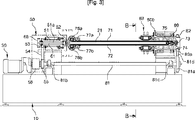
図1は本発明の一実施形態による断面多角形の紙管の製造装置の斜視図、図2は図1に示す製造装置に複数の紙ストリップが巻き付けられる状態を示す平面図、図3は図2のA−A線に沿って取った断面図である。 FIG. 1 is a perspective view of a paper tube manufacturing apparatus having a polygonal cross section according to an embodiment of the present invention, FIG. 2 is a plan view showing a state in which a plurality of paper strips are wound around the manufacturing apparatus shown in FIG. It is sectional drawing taken along the AA line of 2. FIG.
図1〜図3を参照すれば、本実施形態による断面多角形の紙管の製造装置100は、フレーム10と、フレーム10に一端が回転可能に支持され、他端が自由端として配置されたコア組立体20と、予め接着剤が塗布されるとともにコア組立体20に螺旋状に重畳して巻き付けられた複数の紙ストリップ(細長い紙片)a、b、c、d、e、fを、コア組立体20の自由端側に連続的に移送させるための移送部材とを含む。本実施形態において、移送部材は一対の移送ベルト71、72を含む。
1 to 3, a paper
図2を参照すれば、コア組立体20は、細長型であり、その断面の外郭は四角形である。コア組立体20が第1駆動手段30から動力を受けて回転するとき、コア組立体20の外周面に、最下層の紙ストリップa以外に、予め接着剤が塗布された複数のストリップb、c、d、e、fが螺旋状に重畳して巻き付けられる。図2において、未説明符号91はストリップに接着剤を塗布するための接着剤供給装置、92は接着剤塗布ローラーである。図3を参照すれば、フレーム10には、コア組立体20を回転させるための動力を提供するための第1駆動手段30と、第1駆動手段30の動力を受けてコア組立体20に伝達するための第1伝動手段50とが備えられている。また、図2を参照すれば、フレーム10には、一対の移送ベルト71、72に動力を提供するための第2駆動手段40と、第2駆動手段40の動力を受けて一対の移送ベルト71、72に伝達するための第2伝動手段60とが備えられている。第1駆動手段30及び第2駆動手段40はモーターを使用することが好ましく、特に第2駆動手段は、成形されて排出される紙管94の速度とコア組立体20の回転速度をフィードバックして紙管94の排出速度を制御するために、サーボモーターを使用することがより好ましい。
Referring to FIG. 2, the
また、本実施形態の紙管の製造装置100は、コア組立体20と同一角速度で回転するように、フレーム10に第4回転軸80が設置されている。第4回転軸80は、コア組立体20の自由端側に連続的に排出される紙管200が通過するための貫通孔80aが形成されている。中空の第4回転軸80の一端には、コア組立体20の自由端が搖れることを防止し、コア組立体20の自由端側に紙管200がスリップなしに排出され、紙管の四角形を維持するように加圧するための加圧手段83が設置されている。加圧手段83は、第4回転軸80に固定され、第4回転軸と同一角速度で回転することになっており、一対の移送ベルト71、72によってコア組立体20の自由端側に連続的に排出される角形紙管200の対向側面を対称的に加圧するようになっている。加圧手段83が固定された中空の第4回転軸80をコア組立体20と同一角速度で回転させるための動力を伝達するために、第2中空回転軸80の一端には従動プーリー82が固定されている。また、フレーム10には、従動プーリー82に動力を伝達するための動力軸81が一対のベアリング81b、81cに支持され、第1駆動手段30に連結されている。また、動力軸81の一端には、従動プーリー82に動力を伝達する駆動プーリー81aが固定され、駆動プーリー81aと従動プーリー82はタイミングベルト81dを介して連結されている。駆動プーリー81aと従動プーリー82の直径を適切に決定することで、コア組立体20と第4回転軸80の回転角速度を同一にすることができる。
Further, in the paper
図3を参照すれば、第1駆動手段30から動力を受けてコア組立体20を回転させるための動力を伝達するための第1伝動手段50が点線内に概略的に示されている。第1伝動手段50は、フレーム10にベアリングによって回転可能に支持され、貫通孔51aが形成された中空の第1回転軸51と、一側が第1回転軸51に連結され、他側にコア組立体20が固定されたカップリング部材52を含む。第1回転軸51とカップリング部材52とコア組立体20は、回転中心が一致するように一体に固定されているので、同一角速度で回転する。中空の第1回転軸51の他端にはプーリー53が固定され、プーリー53は第1駆動手段30の回転軸に連結されたプーリー55とベルト54を介して連結される。未説明符号56は減速機である。モーター30が回転すれば、プーリー55、ベルト54、プーリー53、第1回転軸51、カップリング部材52を介してコア組立体20に回転動力が伝達されることにより、コア組立体20が回転するようになっている。また、モーター30が回転すれば、伝動軸81、プーリー81a、ベルト81d、プーリー82、中空の第4回転軸80を介して加圧手段83に回転動力が伝達され、加圧手段が紙管200を加圧しながらコア組立体20と同一角速度で回転するようになっている。
Referring to FIG. 3, first transmission means 50 for receiving power from the first drive means 30 and transmitting power for rotating the
図2を参照すれば、第2駆動手段40から動力を受けた後、コア組立体に設置された一対の移送ベルト71、72を駆動するための動力を伝達するための第2伝動手段60が点線内に概略的に示されている。図3を参照すれば、第2伝動手段60は、第1回転軸51の貫通孔51aに挿入され、回転可能にベアリングによって支持された第2回転軸61と、第2回転軸61の回転動力を移送ベルト71、72に伝達するための第3伝動手段とを備えている。図3のH−H線に沿って取った断面図である図9を参照すれば、第3伝動手段は、第2回転軸61に対して直角にカップリング部材52に回転可能に設置された第3回転軸62と、第2回転軸61の動力を直角に配置された第3回転軸62に伝達するために第2回転軸61の端部に設置された傘歯車63と、傘歯車63に直角に動力を伝達するようにかみ合って第3回転軸62に設置された傘歯車64とを含む。また、第3伝動手段は、第3回転軸62の動力をコア組立体20に設置された一対の移送ベルト71、72に伝達するための第4伝動手段を含む。
Referring to FIG. 2, the second transmission means 60 for transmitting power for driving the pair of
図3及び図3のC−C線に沿って取った断面図である図4を参照すれば、コア組立体20は、長い四角棒コア21と、前記四角棒コア21の対向する両側面に固定された一対の長い移送案内部材22とを含む。四角棒コア21の一端はカップリング部材52に固定され、他端は自由端として第4回転軸80の貫通孔80aに挿入されている。それぞれの移送案内部材22は、四角棒コア21の両側面に固定されるための長いベース部22aと、ベース部22aから伸びた上側及び下側案内羽部22a、22cとを備える。ベース部22aは、四角棒コア21の幅より大きな幅を有し、四角棒コア21の両側面に複数のボルト23で固定されている。上側及び下側案内羽部22a、22cは、ベース部22bの幅方向への両端から一定距離だけ離隔して対向するベース部22bに向かって平行に突出して長手方向に一定長さに伸びている。上部移送ベルト71には一対の移送案内部材22の上側案内羽部22aが挿入され、下部移送ベルト72には一対の移送案内部材22の下側案内羽部22cが挿入されている。
Referring to FIG. 4, which is a cross-sectional view taken along the line CC of FIGS. 3 and 3, the
図3、図9及び図8を参照すれば、第3回転軸62に伝達される回転動力を一対の移送ベルト71、72に伝達するための第4伝動手段は、上部及び下部ベルト駆動軸76a、76bと上部及び下部アイドルローラー73、74を含む。上部及び下部ベルト駆動軸76a、76bは、四角棒コア21の固定端側に回転可能に設置されている。上部及び下部アイドルローラー73、74は、移送案内部材22の自由端に一定距離だけ離隔して回転可能にそれぞれ固定されている。上部及び下部ベルト駆動軸76a、76bは、四角棒コア21に固定された一対のブラケット26、27にそれぞれベアリングを介して設置される。環状の上部ベルト71は上部ベルト駆動軸76aを取り囲み、内側に挿入された上側案内羽部22aに案内されて上部アイドルローラー73にかけられている。また、環状の下部ベルト72は下部ベルト駆動軸76bを取り囲み、内側に挿入された下側案内羽部22cによって案内されて下部アイドルローラー74にかけられている。すなわち、上部移送ベルト71は、上部ベルト駆動軸76aと上部アイドルローラー73にかけられ、移送案内部材22の上側案内羽部22aが両側から挿入されており、下部移送ベルト72は、下部ベルト駆動軸76bと下部アイドルローラー74にかけられ、移送案内部材22の下側案内羽部22cが両側から挿入されており、回転時に互いに干渉しないようになっている。
Referring to FIGS. 3, 9 and 8, the fourth transmission means for transmitting the rotational power transmitted to the third
また、図9及び図3のI−I線に沿って取った断面図である図8を参照すれば、第4伝動手段は、第3回転軸62の回転動力を上部及び下部ベルト駆動軸76a、76bにそれぞれ伝達するためのギア65、66、67、68を備える。本実施形態においては、伝動手段としてギアを使用したが、ベルトとプーリーを使用してもかまわない。第3回転軸62の一端に固定されたギア65は、下部ベルト駆動軸76bの一端に固定されたギア66とかみ合っており、下部ベルト駆動軸76bの他端に固定されたギア67は上部ベルト駆動軸76aの一端に固定されたギア68とかみ合っている。よって、ギア65がいずれかの一方向に回転する場合、上部及び下部ベルト駆動軸76a、76bは互いに反対方向に回転するようになっている。したがって、ギア65の回転方向を適切に調節することで、紙ストリップが巻き付けられて当該紙ストリップに接触することになる上部移送ベルト71の、上側案内羽部22aの上部に位置して外側に露出する部分と、紙ストリップが巻き付けられて当該紙ストリップに接触することになる下部移送ベルト72の、下側案内羽部22cの下部に位置して外側に露出する部分とを、コア組立体の自由端側に移動させることができる。
Also, referring to FIG. 8, which is a cross-sectional view taken along the line II in FIGS. 9 and 3, the fourth transmission means transmits the rotational power of the third
本実施形態において、案内羽部22a、22cの外側に位置する上部移送ベルト71と下部移送ベルト72の各部分が、本発明における顕著な特徴である、少なくとも一部がストリップが巻き付けられた前記コア組立体の外周面から露出するように前記コア組立体に設置された移送部材における、露出する部分に相当する。移送ベルト71、72が動力を受けて回転することにより、移送ベルトの露出部分はコア組立体20の自由端側に移動することになり、自由端側に移動する移送ベルト71、72の部分は、コア組立体20の外周面に複数の紙ストリップが螺旋状に巻き付けられて形成される角形紙管200の内周面と連続的に接触して紙管200をコア組立体20の自由端に排出させることになる。
In the present embodiment, each of the
図3を参照すれば、四角棒コア21に回転可能に固定されたアイドルローラー77a、77bは、それぞれ上部ベルト71と下部ベルト72の張力を調節するように移動可能になされている。コア組立体20の自由端側に回転可能に設置されたアイドルローラー75は、下部ベルト72の移動を案内して張力を調節するためのものである。自由端側の上部ベルト71の移動案内と張力調節は下部アイドルローラー74の位置を調節することでなし得る。
Referring to FIG. 3, the idle rollers 77a and 77b fixed to the
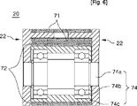
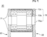
図5は図3のD−D線に沿って取った断面図であって、アイドルローラー75が移送案内部材22のベース部22bにベアリングを介して回転可能に設置された状態を示している。図6は図3のE−E線に沿って取った断面図であって、下部アイドルローラー74に下部ベルト72がかけられており、移送案内部材22のベース部22bにベアリングを介して回転可能に設置された状態を示している。図7は図3のF−F線に沿って取った断面図であって、上部アイドルローラー73に上部ベルト71がかけられており、移送案内部材22のベース部22bにベアリングを介して回転可能に設置された状態を示している。
FIG. 5 is a cross-sectional view taken along the line DD in FIG. 3 and shows a state in which the
図1、図10及び図11を参照すれば、本実施形態の加圧手段83は、上部移送ベルト71及び下部移送ベルト72の露出した面に対して向き合うように、コア組立体20の上側及び下側に対称的に設置された一対のアイドルベルト85を含む。一対のアイドルベルト85は、一対のアイドルローラー86にかけられて循環回転するようになっている。一対のアイドルローラー86はブラケット89に固定されており、ブラケット89は、ガイド棒84によって上下方向に移動可能に拘束されたハウジング87に設置されている。本実施形態において、紙管200の外側面を押す面圧を高めるために、アイドルベルト85を使用したが、ローラー又はスライディングプレートを使用することもできる。また、ブラケット89は、中空の第4回転軸80の端部に形成されたフランジ部80bに固定されたリニアガイド88によって案内されて上下に調節できるようになっている。また、ガイド棒84にはスプリング84aが挿入されるので、一定圧力で成形された紙管の上面を加圧するようになっている。
Referring to FIGS. 1, 10, and 11, the pressurizing
以下、図2及び図3を参照して本実施形態による紙管の製造装置の作動について説明する。 The operation of the paper tube manufacturing apparatus according to this embodiment will be described below with reference to FIGS.
図2に示すように、最下層のストリップを除き、予め接着剤が塗布された複数のストリップをコア組立体20の外周面に一定傾斜角度に重畳して付着させる。ついで、第1駆動手段30及び第2駆動手段40であるモーターを同時に適切な速度比で回転させれば、第1伝動手段50の作動によってコア組立体20が回転するとともに、第2伝動手段60の作動によって、コア組立体20に設置された上部及び下部移送ベルト71、72の露出部分がコア組立体20の自由端に向かって循環して移動する。よって、コア組立体20の外周面に付着された複数の紙ストリップが螺旋状に巻き付けられるとともに、最下層ストリップの内面と接触する上部及び下部移送ベルト71、72によって、コア組立体20に巻き付けられたストリップ200(紙管)が当該コア組立体20の自由端側に移送される。よって、連続的にストリップが巻き付けられて紙管が形成されながら自由端側に排出される。この際に、自由端側に設置された加圧手段によって紙管の上面を加圧すれば、上部及び下部移送ベルト71、72と、これらに接触する紙管の内面との間に生じる摩擦力をさらに大きくでき、紙管の内面と移送ベルトとの間にスリップを生じさせることなく、紙管を円滑に排出できる。
As shown in FIG. 2, a plurality of strips previously coated with an adhesive are attached to the outer peripheral surface of the
図12は本発明の他の実施形態による断面多角形の紙管の製造装置を説明する斜視図、図13は図12に示す実施形態の平面図、図14は図12に示す実施形態の正面図である。 12 is a perspective view for explaining a paper tube manufacturing apparatus having a polygonal cross section according to another embodiment of the present invention, FIG. 13 is a plan view of the embodiment shown in FIG. 12, and FIG. 14 is a front view of the embodiment shown in FIG. FIG.
図1に示す実施形態は、移送ベルトの移動を案内するための一対の移送案内部材を、コア組立体の四角棒コアに固定して剛性を高くしているが、本実施形態のコア組立体は、上部及び下部コアに移送ベルトを設置して上部及び下部コアの間隔を調節して、製造される紙管の幅を容易に変更できるようにした点で、図1に示す実施形態とは違いがある。 In the embodiment shown in FIG. 1, a pair of transfer guide members for guiding the movement of the transfer belt is fixed to the rectangular bar core of the core assembly to increase the rigidity. 1 is different from the embodiment shown in FIG. 1 in that a transfer belt is installed on the upper and lower cores and the distance between the upper and lower cores is adjusted so that the width of the manufactured paper tube can be easily changed. There is a difference.
図12〜図14を参照すれば、本実施形態のコア組立体120は、カップリング部材52に一端が固定された長い上部コア121と、上部コア121から一定距離だけ離隔し、一端がカップリング部材52に固定された長い下部コア122とを含む。本実施形態において、図9に示す第3回転軸62に伝達される回転動力を上部及び下部移送ベルト71、72に伝達するための第4伝動手段として、図1に示す実施形態と同様に、上部及び下部ベルト駆動軸76a、76bと上部及び下部アイドルローラー73、74を備える。上部及び下部ベルト駆動軸76a、76bはそれぞれ上部及び下部コア121、122の固定端側に回転可能に設置され、上部及び下部アイドルローラー73、74はそれぞれ上部及び下部コア121、122の自由端側に回転可能に設置されている。環状の上部ベルト71は、上部ベルト駆動軸76aと上部アイドルローラー73に掛けられており、上部コア121を長手方向に取り囲むコンベヤー状に設置されている。また、環状の下部ベルト72も下部ベルト駆動軸76bと下部アイドルローラー74に掛けられており、下部コア122を長手方向に取り囲むコンベヤー状に設置されている。本実施形態において、第3回転軸62の回転動力を上部及び下部ベルト駆動軸76a、76bにそれぞれ伝達するための伝動手段は、一対の伝動ベルト167、168と複数のプーリー165、166、169、170を含む。プーリー165、166は第3回転軸62の両端に固定されている。プーリー169は下部ベルト駆動軸76bに連結され、プーリー170は上部移送ベルト71の回転方向を転換するための媒介物であって、上部ベルト駆動軸76aに固定されたギア172とプーリー170に固定されたギア171とを介して、上部ベルト駆動軸76aに動力を伝達する。すなわち、上部移送ベルト71における上部コア121の外側面121aを覆う部分と、下部移送ベルト72における下部コア122の外側面122aを覆う部分とが、同時にコア組立体120の自由端側に移動するようにするために、プーリー170の回転方向を切り替えることによって動力を上部ベルト駆動軸76aに伝達する一対のかみ合ったギア171、172が、上部ベルト駆動軸76aとプーリー170の軸にそれぞれ設置されている。
Referring to FIGS. 12 to 14, the
本実施形態において、上部コア121の外側面121aに位置する上部移送ベルト71の部分と下部コア122の外側面122aに位置する下部移送ベルト72の部分とが、本発明の顕著な特徴である、少なくとも一部がストリップが巻き付けられるコア組立体の外周面から露出するようにコア組立体に設置された移送部材における、露出する部分に相当する。移送ベルト71、72が動力を受けて回転することにより、移送ベルト71、72の露出部分はコア組立体20の自由端側に移動することになり、移送ベルト71、72はコア組立体120の外周面に複数の紙ストリップが螺旋状に巻き付けられて形成される角形紙管200の内周面と連続的に接触して、紙管200をコア組立体120の自由端側に移送させることになる。
In this embodiment, the portion of the
また、本実施形態の紙管の製造装置は、カップリング部材52に固定された上部コア121と下部コア122間の間隔を調節することができるようになっているので、製造しようとする紙管の幅を変更することができる。すなわち、カップリング部材52にはリニアガイド153が設置されており、上部コア12と下部コア122はリニアガイド153に移動可能に設置された一対のブラケット154、155にそれぞれ固定されている。
Further, the paper tube manufacturing apparatus of this embodiment can adjust the distance between the
また、本実施形態の紙管の製造装置は、コア組立体120の自由端に連続的に製造されて排出される紙管を適当な長さに切断するための紙管カッティング手段130をさらに備えている。紙管カッティング手段130は、コア組立体120の長手方向に移動可能にフレーム10に設置されたベース131と、コア組立体120の長手方向に対して垂直方向に移動可能に前記ベースに設置されたカッター132とを含む。フレーム10には、ベース131を移動させるための動力を提供するためのモーター146と、ベース131の移動を案内するための一対のリニアガイド144とが設置されている。ベース131は、紙管の切断の際に、モーター146の軸に設置されたボールスクリュー145によって紙管が排出される速度と同一速度で移動するようになっている。
The paper tube manufacturing apparatus according to the present embodiment further includes a paper tube cutting means 130 for cutting the paper tube continuously manufactured and discharged from the free end of the
また、ベース131には、カッター132を紙管の排出方向に対して垂直方向に移送させるためのベッド133が設置されており、ベッド133には垂直移送ガイド140が設置されている。ベッド133の上部には、移送板139が装着されており、装着板139の上部にはカッター132とカッター132を駆動するためのモーター134が装着されている。カッター132とモーター134は、紙管の切断中に微細に紙管の排出方向に移動できるようにリニアガイドを備えた装着板139に設置されている。図示のように、カッター132は回転する円形の刃又は鋸の刃を使用することが好ましい。
The
また、紙管カッティング手段130はベース131に支持されるもので、コア組立体120と同一角速度で回転するように設置され、コア組立体120の自由端側に排出される紙管が通過するための貫通孔146aが形成された中空の第4回転軸146をさらに含む。図示しなかったが、第4回転軸には、排出される紙管を切断するとき、紙管の端部がカッターによって押されることを防止するための装置が設置される。
The paper tube cutting means 130 is supported by the
本実施形態の紙管の製造装置の作動は、コア組立体120の自由端に排出される紙管を紙管カッティング手段130で切断することを除き、図1に示す実施形態の紙管の製造装置の作動と同様であるのでその説明は省略する。
The operation of the paper tube manufacturing apparatus of this embodiment is the same as that of the embodiment shown in FIG. 1 except that the paper tube discharged to the free end of the
図15は本発明のさらに他の実施形態による断面多角形の紙管の製造装置を説明する概略図、図16は図15のQ−Q線に沿って取った断面図、図17は図15のR−R線に沿って取った断面図、図18は図15のS−S線に沿って取った断面図である。 FIG. 15 is a schematic diagram for explaining an apparatus for manufacturing a polygonal cross-section paper tube according to still another embodiment of the present invention, FIG. 16 is a cross-sectional view taken along line QQ in FIG. 15, and FIG. FIG. 18 is a cross-sectional view taken along line S-S in FIG. 15.
本実施形態の紙管の製造装置が図1に示す紙管の製造装置と違う点は、紙管の移送部材としてコア組立体20に設置された移送ギア79a、79b、79d、79eを使用した点である。本実施形態のコア組立体20は、一端がカップリング部材52に固定された長い四角棒コア21と、四角棒コア21の対向する両側面に固定された一対の長い移送案内部材22とを含む。それぞれの移送案内部材22は、四角棒コア21の幅より大きな幅を有し、四角棒コア21の両側面に固定されたベース部22bと、前記ベース部22bの幅方向の両端から一定距離だけ離隔して、対向するベース部22bに向かって平行に突出して長手方向に一定長さだけ伸びた上側及び下側案内羽部22a、22cとを備えている。一対の移送ギア79a、79bは、それらの歯先円がそれぞれ移送案内部材22より外側に突出するように、案内羽部22a、22cが設けられていない移送案内部材22の自由端側の端部に回転可能に設けられている。ギア79cは、隣合う一対の移送ギア79d、79eに動力を伝達するための伝動ギアである。
The paper tube manufacturing apparatus of this embodiment is different from the paper tube manufacturing apparatus shown in FIG. 1 in that transfer gears 79a, 79b, 79d, and 79e installed in the
図9に示す第3回転軸62の回転動力を移送ギア79a、79bに伝達するための伝動手段は、四角棒コア21の固定端側に回転可能に設置されたベルト駆動軸76と、ベルト駆動軸76に第3回転軸62の回転動力を伝達するための図示しないギアと、コア組立体20の自由端に設置されたベルト従動軸77と、ベルト駆動軸76とベルト従動軸77を連結するベルト75と、ベルト従動軸77に固定されて移送ギア79aとかみ合うように設置されたギア78とから構成される。
The transmission means for transmitting the rotational power of the third
本実施形態において、移送案内部材22より外側に突出したそれぞれの移送ギア79a、79b、79c、79dの歯先円部分が、本発明の顕著な特徴である、少なくとも一部がコア組立体のストリップが巻き付けられる外周面から露出するようにコア組立体に設置された移送部材における、露出する部分に相当する。ベルト75の動力を受けて移送ギア79a、79b、79c、79dが回転することにより、移送案内部材22より外側に突出した歯先円部分がコア組立体20の自由端側に移動することになり、歯先円部分は、コア組立体120の外周面に複数の紙ストリップが螺旋状に巻き付けられて形成される角形紙管の内周面と連続的に接触して、紙管をコア組立体20の自由端側に移送させることになる。
In this embodiment, the tip of each
図19は本発明のさらに他の実施形態による断面多角形の紙管の製造装置を説明する概略図、図20は図19のN−N線に沿って取った断面図、図21は図19のP−P線に沿って取った断面図、図22は図19のT−T線に沿って取った断面図である。 FIG. 19 is a schematic view for explaining an apparatus for manufacturing a polygonal cross-section paper tube according to still another embodiment of the present invention, FIG. 20 is a cross-sectional view taken along line NN of FIG. 19, and FIG. FIG. 22 is a cross-sectional view taken along the line TT in FIG. 19, and FIG. 22 is a cross-sectional view taken along the line TT in FIG.
本実施形態の紙管の製造装置が図1に示す紙管の製造装置と違う点は、紙管の移送部材として、コア組立体20に設置された移送スクリューを使用した点である。
The difference between the paper tube manufacturing apparatus of the present embodiment and the paper tube manufacturing apparatus shown in FIG. 1 is that a transfer screw installed in the
図19及び図20を参照すれば、本実施形態のコア組立体320は、一端がカップリング部材52に固定され、他端が自由端である長い四角棒コア321を含み、四角棒コア321のカップリング部材52に連結された部分から四つの角部が長手方向に一定長さだけ除去されている。また、それぞれの移送スクリュー322、323、324、325は、四角棒コア321の除去された四つの角部にそれぞれ挿入され、外周面の一部が外部に露出するように設置され、一端は前記カップリング部材52に回転可能に設置され、他端は四角棒コア321の除去されなかった部分にそれぞれ回転可能に設置されている。図示されていないが、それぞれの移送スクリュー322、323、324、325の外周面にはネジ部が形成されている。図21を参照すれば、カップリング部材321に固定されたそれぞれの移送スクリュー322、323、324、325の端部には従動ギア326、327、328、329がそれぞれ固定されている。それぞれのギアの中央には、第2回転軸61の端部に固定された駆動ギア61aがかみ合うように設置されている。また、本実施形態の紙管の製造装置において、加圧手段383は紙管の角部を加圧するためのテーパーローラ384を使用するという点で、図1に示す実施形態の加圧手段83と違いがある。
19 and 20, the
本実施形態においては、四角棒コア321の除去された角に回転可能に設置された移送スクリュー322、323、324、325の外周面に形成され、紙管の内側面と接するネジ部が、本発明の顕著な特徴である、少なくとも一部がコア組立体のストリップが巻き付けられる外周面から露出するようにコア組立体に設置された移送部材における、露出する部分に相当する。駆動ギア61aから動力を受けて移送スクリュー322、323、324、325が回転することにより、移送スクリューのネジ部がコア組立体20の自由端側に移動するとともに、角形紙管200の内周面と連続的に接触して紙管をコア組立体20の自由端側に移送させることになる。
In the present embodiment, a screw portion that is formed on the outer peripheral surface of the transfer screws 322, 323, 324, and 325 rotatably installed at the corner from which the
図22は皺(波型に形成された部分)がストリップの長手方向に平行な片面段ボールストリップを使用して角形紙管を製造する状態の説明図である。図2及び図22を参照すれば、本発明による方法と装置を利用すれば、コア組立体20にライナー原紙a、e、fと片面段ボールb、c、dを図示の順に配置して角形紙管を製造することができる。本発明による装置は、コア組立体の内部から外部に露出した移送部材の一部がコア組立体の自由端側に移動するようにになっているので、段ボールストリップの皺を損傷せずに紙管を製造することができる。本実施形態では片面段ボールストリップを使用しているが、これに限定されるものではなく、両面段ボールストリップを使用することもできる。また、片面段ボールの皺(波型の)中間紙の方向を反対に(成形される角形紙管の内側面に向かうようにして)して、紙管を製造することもできる。
FIG. 22 is an explanatory view of a state in which a square paper tube is manufactured using a single-sided cardboard strip whose ridges (portions formed in a corrugated shape) are parallel to the longitudinal direction of the strip. 2 and 22, when the method and apparatus according to the present invention is used, the liner base papers a, e, and f and the single-sided cardboards b, c, and d are arranged in the order shown in the drawing in the
本発明によれば、回転するコアに螺旋状に重畳して巻き付けられた複数の紙ストリップを、コアの内部で移動する移送部材によってコアから排出することで、より厚肉の紙管を製造することができることになる。また、本発明によれば、厚肉の角形紙管を製造することができるので、強度に優れた角形紙管を提供することになる。また、本発明によれば、片面段ボールからなる紙ストリップで角形紙管を製造しても段ボールの皺が損傷しないようにすることができる。 According to the present invention, a thicker paper tube is manufactured by discharging a plurality of paper strips wound in a spiral manner on a rotating core from the core by a transfer member that moves inside the core. Will be able to. Further, according to the present invention, since a thick square paper tube can be manufactured, a square paper tube excellent in strength is provided. Further, according to the present invention, even when a square paper tube is manufactured with a paper strip made of single-sided corrugated cardboard, the corrugated cardboard can be prevented from being damaged.
本発明によって、螺旋状に重畳して巻き付けて紙管を連続的に生産することにより、生産性に優れ、厚くて強度に優れた角形紙管を提供することになれば、強度に優れた紙パレットを安価で提供することができることになる。強度に優れた紙パレットを提供すれば、重量物の運送に使用された木材パレットを紙パレットで取り替えることができるので、伐木を減少させることで環境の保存にも寄与することになる。 According to the present invention, if a paper tube is continuously produced by being spirally overlapped and wound to provide a square paper tube having excellent productivity and being thick and excellent in strength, A pallet can be provided at low cost. By providing a paper pallet with excellent strength, it is possible to replace the wood pallet used to transport heavy objects with a paper pallet, which contributes to environmental conservation by reducing the number of felled trees.
先に説明し、図面に示す本発明の実施形態は本発明の技術的思想を限定するものとして解釈されてはいけない。本発明の保護範囲は請求範囲に記載した事項によってだけ制限され、本発明の技術分野で通常の知識を持った者であれば、本発明の技術的思想を多様な形態に改良ないし変更することが可能である。したがって、このような改良ないし変更は、通常の知識を持った者に自明なものである限り、本発明の保護範囲に属するものである。 The embodiments of the present invention described above and shown in the drawings should not be construed as limiting the technical idea of the present invention. The scope of protection of the present invention is limited only by the matters described in the claims, and those skilled in the technical field of the present invention can improve or change the technical idea of the present invention into various forms. Is possible. Therefore, such improvements or modifications are within the protection scope of the present invention as long as they are obvious to those having ordinary knowledge.
10 フレーム、20 コア組立体、30 第1駆動手段、40 第2駆動手段、50 第1伝動手段、60 第2伝動手段、70 移送部材、80 第4回転軸。 10 frame, 20 core assembly, 30 first driving means, 40 second driving means, 50 first transmission means, 60 second transmission means, 70 transfer member, 80 fourth rotating shaft.
Claims (20)
少なくとも一部がストリップが巻き付けられた前記コアの外周面から連続的に露出して前記コアの長手方向に移動するように前記コアの内部に設置された移送部材を、前記コアの外周面に巻き付けられた前記最下層のストリップの内面に接触させることによって、前記コアに巻き付けられた前記複数の紙ストリップを長手方向に連続的に移送する移送工程と、を含むことを特徴とする断面多角形の紙管の製造方法。In addition to the lowermost layer strip, a winding step in which a plurality of paper strips coated with an adhesive in advance are spirally superimposed on the outer peripheral surface of a rotating core having a polygonal cross section, and
A transfer member installed inside the core is wound around the outer peripheral surface of the core so as to be continuously exposed from the outer peripheral surface of the core around which at least a part is wound and moved in the longitudinal direction of the core. A transfer step of continuously transferring the plurality of paper strips wound around the core in a longitudinal direction by contacting an inner surface of the lowermost strip, which is formed on the lowermost layer. Paper tube manufacturing method.
前記複数の紙ストリップの少なくとも一つは片面段ボールストリップであることを特徴とする、請求項1に記載の断面多角形の紙管の製造方法。The transfer step is performed while simultaneously pressing the upper surfaces of the portions of the plurality of paper strips wound around which the transfer member is in contact by a pressurizing unit installed on a frame that rotates at the same angular velocity as the core.
The method of manufacturing a paper tube having a polygonal cross section according to claim 1, wherein at least one of the plurality of paper strips is a single-sided cardboard strip.
最下層のストリップ以外に、予め接着剤が塗布された複数の紙ストリップが、外周面に螺旋状に重畳して巻き付けられるように、一端が前記フレームによって回転可能に支持され、他端が自由端とされ、外周面が所定の多角形を有する細長型のコア組立体と、
前記コア組立体を回転させるための動力を提供する第1駆動手段と、
前記第1駆動手段の動力を受けて前記コア組立体に伝達する第1伝動手段と、
少なくとも一部が前記複数の紙ストリップが巻き付けられた前記コア組立体の外周面から露出するように前記コア組立体に設置される部材であって、動力を受けて、前記部材の露出する部分が前記コア組立体の自由端側に移動するように設けられ、前記コア組立体の外周面に巻き付けられる前記複数の紙ストリップのうち、前記最下層のストリップの内面に、連続的に露出する前記部分が接触して、前記コア組立体に巻き付けられる前記複数の紙ストリップを連続的に前記コア組立体の前記自由端側に移送する移送部材と、
前記移送部材の前記部分を、コア組立体の外周面から連続的に露出させるための動力を提供する第2駆動手段と、
前記第2駆動手段の動力を受けて前記移送部材に伝達する第2伝動手段と、を含むことを特徴とする断面多角形の紙管の製造装置。Frame,
Besides lowermost strip, a plurality of paper strips previously adhesive is applied is, as wound et be superimposed helically on the outer peripheral surface, one end of which it is rotatably supported by the frame, the free other end An elongated core assembly having an end and an outer peripheral surface having a predetermined polygon;
First driving means for providing power for rotating the core assembly;
First transmission means for receiving power from the first drive means and transmitting the power to the core assembly;
A member installed on the core assembly so that at least a part thereof is exposed from the outer peripheral surface of the core assembly around which the plurality of paper strips are wound, and the exposed portion of the member receives power. Of the plurality of paper strips that are provided to move to the free end side of the core assembly and are wound around the outer peripheral surface of the core assembly, the portion that is continuously exposed on the inner surface of the lowermost strip A plurality of paper strips wound around the core assembly and continuously transferring the paper strip to the free end side of the core assembly;
Second driving means for providing power for continuously exposing the portion of the transfer member from the outer peripheral surface of the core assembly;
And a second transmission means for receiving the power of the second drive means and transmitting it to the transfer member.
前記第2伝動手段は、前記第2駆動手段から動力を受けて回転するように、前記第1回転軸の貫通孔に挿入され、回転可能に第1回転軸に支持された第2回転軸と、前記第2回転軸の回転動力を前記移送部材に伝達するための第3伝動手段と、を含むことを特徴とする請求項3に記載の断面多角形の紙管の製造装置。The first transmission means is rotatably supported by the frame so as to rotate by receiving power from the first drive means, and has a hollow first rotation shaft having a through hole formed in a longitudinal direction, and one side of the first transmission means A coupling member coupled to the first rotating shaft and coupled to the core assembly on the other side;
The second transmission means is inserted into a through-hole of the first rotation shaft so as to rotate by receiving power from the second drive means, and a second rotation shaft rotatably supported by the first rotation shaft. 4. The apparatus for manufacturing a paper tube having a polygonal cross section according to claim 3, further comprising: third transmission means for transmitting rotational power of the second rotating shaft to the transfer member.
前記第3伝動手段は、前記第2回転軸に対して直角に前記カップリング部材に回転可能に設置された第3回転軸と、前記第2回転軸の動力を前記第3回転軸に伝達するために、第2及び第3回転軸にそれぞれ設置されてかみ合う一対の傘歯車と、前記第3回転軸の回転動力を前記一対の移送ベルトに伝達するための第4伝動手段と、をさらに含むことを特徴とする請求項4に記載の断面多角形の紙管の製造装置。The transfer member is installed so that a part of the transfer member is exposed in the longitudinal direction from the outer peripheral surface of the core assembly, and the exposed part of the core assembly faces the free end side of the core assembly. Including a pair of transfer belts installed on the outer peripheral surface;
The third transmission means transmits the power of the second rotating shaft to the third rotating shaft, and a third rotating shaft that is rotatably installed on the coupling member at a right angle to the second rotating shaft. For this purpose, it further includes a pair of bevel gears installed on and engaged with the second and third rotating shafts respectively, and a fourth transmission means for transmitting the rotational power of the third rotating shafts to the pair of transfer belts. The apparatus for manufacturing a paper tube having a polygonal cross section according to claim 4.
前記第3伝動手段は、前記第2回転軸に対して直角に前記カップリング部材に回転可能に設置された第3回転軸と、前記第2回転軸の動力を前記第3回転軸に伝達するために、第2及び第3回転軸にそれぞれ設置されてかみ合う一対の傘歯車と、前記第3回転軸の回転動力を前記一対の移送ギアに伝達するための第5伝動手段と、をさらに含むことを特徴とする請求項4に記載の断面多角形の紙管の製造装置。The transfer member is installed to rotate about a rotation shaft installed perpendicular to the longitudinal direction of the core assembly, and a part of the transfer member is exposed from the facing portion of the outer peripheral surface of the core assembly. Including a pair of installed transfer gears;
The third transmission means transmits the power of the second rotating shaft to the third rotating shaft, and a third rotating shaft that is rotatably installed on the coupling member at a right angle to the second rotating shaft. For this purpose, it further includes a pair of bevel gears installed on and engaged with the second and third rotating shafts, respectively, and fifth transmission means for transmitting the rotational power of the third rotating shaft to the pair of transfer gears. The apparatus for manufacturing a paper tube having a polygonal cross section according to claim 4.
前記第3伝動手段は、前記第2回転軸に設置された駆動ギアと、前記駆動ギアとかみ合うように、前記それぞれの移送スクリューの一端に固定設置された複数の従動ギアと、を含むことを特徴とする請求項4に記載の断面多角形の紙管の製造装置。One end of the transfer member is rotatably installed on the coupling member, and the other end is fixedly installed on the core assembly so that a part of the transfer member is exposed in the longitudinal direction from the outer peripheral surface of the core assembly. A plurality of transfer screws,
The third transmission means includes a drive gear installed on the second rotating shaft and a plurality of driven gears fixedly installed at one ends of the respective transfer screws so as to mesh with the drive gear. The apparatus for producing a paper tube having a polygonal cross section according to claim 4.
前記中空の第4回転軸に固定され、前記コア組立体の自由端に巻き付けられた前記複数の紙ストリップのうち、最上層のストリップの上面を対称的に加圧するための加圧手段と、をさらに含むことを特徴とする請求項5ないし7のいずれか1項に記載の断面多角形の紙管の製造装置。A through-hole that is supported by the frame and is installed so as to rotate at the same angular velocity as the core assembly and through which the paper tubes wound with the plurality of paper strips discharged to the free end side of the core assembly pass. A hollow fourth rotating shaft formed with:
Pressurizing means for symmetrically pressing the upper surface of the uppermost strip among the plurality of paper strips fixed to the hollow fourth rotating shaft and wound around the free end of the core assembly; The apparatus for manufacturing a paper tube having a polygonal cross section according to any one of claims 5 to 7, further comprising:
前記一対の移送ベルトは、前記移送案内部材の対向する上側及び下側案内羽部にそれぞれ巻き付けられるように設置され、
前記第4伝動手段は、前記コア組立体の四角棒コアの固定端側に回転可能に設置され、上部移送ベルトがかけられた上部ベルト駆動軸及び下部移送ベルトがかけられた下部ベルト駆動軸と、コア組立体の移送案内部材の自由端に一定距離だけ離隔して回転可能にそれぞれ固定され、上部移送ベルトがかけられた上部アイドルローラー及び下部移送ベルトがかけられた下部アイドルローラーと、前記上部及び下部ベルト駆動軸にそれぞれ前記第3回転軸の回転動力を伝達するためのギアと、を含むことを特徴とする請求項5に記載の断面多角形の紙管の製造装置。The core assembly includes a long rectangular bar core having one end fixed to the coupling member, and a pair of long movement guide member fixed to the opposite sides of the rectangular rod core, before KiUtsuri feed guide Each of the members has a width larger than the width of the square bar core, a base portion fixed to both side surfaces of the square bar member, and a base that is spaced apart from both ends of the base portion in the width direction by a certain distance. The upper and lower guide wings project in parallel to the part side and extend by a certain length in the longitudinal direction,
The pair of transport belts is disposed on the upper and lower guide wing portions opposing the front KiUtsuri feed guide member so as to be respectively wound,
The fourth transmission means is rotatably installed on the fixed end side of the square bar core of the core assembly, and an upper belt drive shaft on which an upper transfer belt is hung and a lower belt drive shaft on which a lower transfer belt is hung An upper idler roller on which an upper transfer belt is hung and a lower idler roller on which a lower transfer belt is hung, each of which is rotatably fixed to a free end of a transfer guide member of the core assembly by a predetermined distance; And a gear for transmitting the rotational power of the third rotary shaft to the lower belt drive shaft and a polygonal cross-section paper tube manufacturing apparatus according to claim 5.
前記一対の移送ベルトはそれぞれ上部及び下部コアを長手方向に取り囲むように設置され、
前記第4伝動手段は、前記上部及び下部コアそれぞれの固定端側に回転可能に設置され、上部移送ベルトがかけられた上部ベルト駆動軸及び下部移送ベルトがかけられた下部ベルト駆動軸と、前記上部及び下部コアそれぞれの自由端に回転可能に設置され、上部移送ベルトがかけられた上部アイドルローラー及び下部移送ベルトがかけられた下部アイドルローラーと、前記上部及び下部ベルト駆動軸にそれぞれ前記第3回転軸の回転動力を伝達するための伝動手段と、を含むことを特徴とする請求項5に記載の断面多角形の紙管の製造装置。The core assembly includes a long upper core having one end fixed to the coupling member, and a long lower core having one end fixed to the coupling member at a predetermined distance from the upper core,
The pair of transfer belts are respectively installed so as to surround the upper and lower cores in the longitudinal direction,
The fourth transmission means is rotatably installed on the fixed end side of each of the upper and lower cores, and an upper belt drive shaft on which an upper transfer belt is hung and a lower belt drive shaft on which a lower transfer belt is hung, and An upper idler roller on which an upper transfer belt is hung, a lower idler roller on which a lower transfer belt is hung, and a third idler on each of the upper and lower belt drive shafts. 6. The apparatus for manufacturing a paper tube having a polygonal cross section according to claim 5, further comprising transmission means for transmitting rotational power of the rotary shaft.
前記中空の第4回転軸に固定され、前記コア組立体の自由端に巻き付けられた前記複数の紙ストリップのうち、最上層ストリップの上面を対称的に加圧するための加圧手段と、をさらに含むことを特徴とする請求項13に記載の断面多角形の紙管の製造装置。A through hole through which the paper tube around which the plurality of paper strips wound is supported by the frame and rotated at the same angular velocity as the core assembly and discharged to the free end side of the core assembly passes. A hollow fourth rotating shaft formed with a hole;
Pressurizing means for symmetrically pressurizing the upper surface of the uppermost strip among the plurality of paper strips fixed to the hollow fourth rotating shaft and wound around the free end of the core assembly; The apparatus for manufacturing a paper tube having a polygonal cross section according to claim 13, comprising:
前記紙管カッティング手段は、前記ベースに支持され、前記コア組立体と同一角速度で回転するように設置され、前記コア組立体の自由端側に排出される前記複数の紙ストリップの巻き付けられた紙管が通過するための貫通孔が形成された中空の第5回転軸をさらに含むことを特徴とする請求項14に記載の断面多角形の紙管の製造装置。The pressurizing unit is installed symmetrically on the surface side of the core assembly on which the upper belt and the lower belt are installed, and is supported by an elastic member so as to pressurize the upper surface of the wound strip with a constant pressure. Including
The paper tube cutting means is supported by the base, is installed so as to rotate at the same angular velocity as the core assembly, and is a paper around which the plurality of paper strips are discharged to the free end side of the core assembly. The apparatus for producing a paper tube having a polygonal cross section according to claim 14, further comprising a hollow fifth rotating shaft formed with a through hole for allowing the tube to pass therethrough.
前記一対の移送ギアは、前記移送案内部材の案内羽部が除去された自由端に外周面の一部がそれぞれ移送案内部材の幅より上部に突出するように回転可能に固定され、
前記第5伝動手段は、前記四角棒コアの固定端側に回転可能に設置されたベルト駆動軸と、前記ベルト駆動軸に前記第3回転軸の回転動力を伝達するためのギアと、前記移送案内部材の自由端に設置されたベルト従動軸と、前記ベルト駆動軸とベルト従動軸を連結する伝動ベルトと、前記ベルト従動軸に固定され、前記移送ギアとかみ合うように設置されたギアとを含むことを特徴とする請求項6に記載の断面多角形の紙管の製造装置。The core assembly includes a long rectangular bar core is one end is fixed to said coupling member, and a pair of long movement guide member fixed to the opposite sides of the rectangular rod core, before KiUtsuri feed Each of the guide members has a width larger than the width of the square bar core, a base portion fixed to both side surfaces of the square bar member, and a base that is spaced apart from the both ends in the width direction of the base portion by a certain distance. The upper and lower guide wings projecting parallel to the part side and extending by a certain length in the longitudinal direction,
Transfer gear before Symbol a pair, said part of the outer circumferential surface on the free end of the guide wing portions are removed in the transfer guide member is rotatably fixed so as to protrude from the upper width of the respective movement guide member,
The fifth transmission means includes a belt drive shaft rotatably installed on the fixed end side of the square bar core, a gear for transmitting the rotational power of the third rotary shaft to the belt drive shaft, and the transfer A belt driven shaft installed at the free end of the guide member, a transmission belt connecting the belt drive shaft and the belt driven shaft, and a gear fixed to the belt driven shaft and installed to mesh with the transfer gear. The apparatus for manufacturing a paper tube having a polygonal cross section according to claim 6.
前記中空の第4回転軸に固定され、前記コア組立体の自由端に巻き付けられた前記複数の紙ストリップのうち、最上層ストリップの上面を対称的に加圧するための加圧手段と、をさらに含むことを特徴とする請求項17に記載の断面多角形の紙管の製造装置。A through hole through which the paper tube around which the plurality of paper strips wound is supported by the frame and rotated at the same angular velocity as the core assembly and discharged to the free end side of the core assembly passes. A hollow fourth rotating shaft formed with a hole;
Pressurizing means for symmetrically pressurizing the upper surface of the uppermost strip among the plurality of paper strips fixed to the hollow fourth rotating shaft and wound around the free end of the core assembly; The apparatus for manufacturing a paper tube having a polygonal cross section according to claim 17.
前記移送スクリューは、前記四角棒コアの除去された角部にそれぞれ挿入され、外周面の一部が外部に露出するように設置され、一端が前記カップリング部材に回転可能に設置され、他端は四角棒コアにそれぞれ回転可能に設置されることを特徴とする請求項7に記載の断面多角形の紙管の製造装置。The core assembly includes a long rectangular bar core, one end of which is fixed to the coupling member, and four corners are removed from the portion connected to the coupling member of the rectangular bar core by a certain length in the longitudinal direction. And
The transfer screw is inserted into each of the removed corners of the square bar core, installed so that a part of the outer peripheral surface is exposed to the outside, one end is rotatably installed on the coupling member, and the other end The apparatus for manufacturing a paper tube having a polygonal cross section according to claim 7, wherein each is installed rotatably on each square bar core.
前記中空の第4回転軸に固定され、前記コア組立体の自由端に巻き付けられた前記複数の紙ストリップのうち、最上層ストリップの上面を対称的に加圧するための加圧手段と、をさらに含むことを特徴とする請求項19に記載の断面多角形の紙管の製造装置。A through hole through which the paper tube around which the plurality of paper strips wound is supported by the frame and rotated at the same angular velocity as the core assembly and discharged to the free end side of the core assembly passes. A hollow fourth rotating shaft formed with a hole;
Pressurizing means for symmetrically pressurizing the upper surface of the uppermost strip among the plurality of paper strips fixed to the hollow fourth rotating shaft and wound around the free end of the core assembly; 20. The apparatus for manufacturing a paper tube having a polygonal cross section according to claim 19.
Applications Claiming Priority (2)
| Application Number | Priority Date | Filing Date | Title |
|---|---|---|---|
| KR20050039872 | 2005-05-12 | ||
| PCT/KR2006/001664 WO2006121253A1 (en) | 2005-05-12 | 2006-05-03 | Method and apparatus for producing paper tube having polygonal cross section, and paper tube manufactured by the method |
Publications (2)
| Publication Number | Publication Date |
|---|---|
| JP2008540183A JP2008540183A (en) | 2008-11-20 |
| JP4564089B2 true JP4564089B2 (en) | 2010-10-20 |
Family
ID=37396728
Family Applications (1)
| Application Number | Title | Priority Date | Filing Date |
|---|---|---|---|
| JP2008511046A Expired - Fee Related JP4564089B2 (en) | 2005-05-12 | 2006-05-03 | Method and apparatus for manufacturing polygonal paper tube |
Country Status (10)
| Country | Link |
|---|---|
| US (2) | US20080060747A1 (en) |
| EP (2) | EP1883528A4 (en) |
| JP (1) | JP4564089B2 (en) |
| KR (1) | KR100746170B1 (en) |
| CN (1) | CN101171123B (en) |
| AU (1) | AU2006244804B2 (en) |
| BR (1) | BRPI0610230A2 (en) |
| MX (1) | MX2007014184A (en) |
| RU (1) | RU2393092C2 (en) |
| WO (1) | WO2006121253A1 (en) |
Families Citing this family (19)
| Publication number | Priority date | Publication date | Assignee | Title |
|---|---|---|---|---|
| KR100746170B1 (en) | 2005-05-12 | 2007-08-03 | 주식회사 다인기술 | Method and apparatus for producing paper tube having polygonal cross section, and paper tube manufactured by the method |
| KR100734891B1 (en) * | 2007-04-05 | 2007-07-03 | 주식회사 무진네오테크 | Manufacturing device of spiral plate for underground anchor and rock bolt |
| KR100975518B1 (en) * | 2009-12-21 | 2010-08-11 | 송시영 | Paper strip |
| CN102285152B (en) * | 2011-08-18 | 2013-02-20 | 黄平 | Equipment for manufacturing square paper pipe |
| CN103373001A (en) * | 2012-04-26 | 2013-10-30 | 王仁泉 | Full-automatic auger-type heteromorphism paper tube manufacturing equipment |
| US9756991B2 (en) | 2013-02-21 | 2017-09-12 | The Procter & Gamble Company | Fibrous cores |
| CA2902033A1 (en) | 2013-02-21 | 2014-08-28 | The Procter & Gamble Company | A method of manufacturing fibrous cores |
| WO2014130440A1 (en) | 2013-02-21 | 2014-08-28 | The Procter & Gamble Company | Fibrous cores |
| CN103317775B (en) * | 2013-07-08 | 2015-11-25 | 吴江久升纸业有限公司 | Pipe in paper tube supporting and shaping |
| PL3099481T3 (en) * | 2014-01-29 | 2018-08-31 | Futura S.P.A. | Equipment and method for the production of cardboard tubes |
| CN104085133B (en) * | 2014-07-08 | 2017-03-15 | 上海绿顺包装机械有限公司 | A kind of stacked paper square tube shaped device of continuous winding |
| US11167512B2 (en) * | 2015-01-20 | 2021-11-09 | Jonathan C. Fragoso | Manufacturing apparatus |
| CN104897881B (en) * | 2015-05-04 | 2016-06-29 | 浙江三信智能机械科技有限公司 | A kind of control device for controlling paper tube to rotate |
| KR101875521B1 (en) | 2016-06-30 | 2018-08-09 | 송현민 | Adhensives application unit for paper pipe package in automatic process system |
| KR101701721B1 (en) | 2016-06-30 | 2017-02-02 | 송현민 | Automatic process system for paper pipe package |
| CN113165301A (en) | 2018-10-13 | 2021-07-23 | 亚历山大·斯洛克 | Package maker |
| IT201900015500A1 (en) | 2019-09-03 | 2021-03-03 | Montrade S P A | SPIRAL TUBE SHAPE AND MECHANISM FOR FORMING A TAPE MATERIAL IN THE SHAPE OF A SPIRAL WINDED TUBE |
| CN112277388B (en) * | 2020-09-16 | 2022-08-26 | 青岛科技大学 | Automatic processing and packaging device for squeezable paper straws |
| CN113211878B (en) * | 2021-04-02 | 2022-06-17 | 东莞市立韵精密金属科技有限公司 | Device for preparing spiral winding type smoke pipe by utilizing torsion |
Family Cites Families (60)
| Publication number | Priority date | Publication date | Assignee | Title |
|---|---|---|---|---|
| US1319455A (en) * | 1919-10-21 | Corrugated-paper tube | ||
| US663438A (en) * | 1900-01-22 | 1900-12-11 | James J Hinde | Method of forming curved articles from celluform board. |
| US726894A (en) * | 1901-02-04 | 1903-05-05 | J W Sefton Mfg Company | Paper mailing-tube. |
| US2016273A (en) * | 1934-09-14 | 1935-10-08 | Harry N Atwood | Built-up composite cellular structure |
| US2738153A (en) * | 1952-03-29 | 1956-03-13 | Signode Steel Strapping Co | Composite pallet |
| US2709400A (en) * | 1952-10-22 | 1955-05-31 | Paramount Paper Tube Corp | Tube winding machines |
| US3068934A (en) * | 1954-01-15 | 1962-12-18 | Nicolet Ind Inc | Apparatus for producing helical air cell pipe covering |
| US2788840A (en) * | 1954-01-15 | 1957-04-16 | Nicolet Ind Inc | Method for producing pipe covering and the like |
| US2777501A (en) * | 1954-07-30 | 1957-01-15 | Nat Fibre Glass Co Inc | Apparatus for continuously forming plastic tubing |
| US2877150A (en) * | 1955-05-11 | 1959-03-10 | Marion E Wilson | Method of manufacturing pipes, conduits, and the like |
| US2893296A (en) * | 1956-05-17 | 1959-07-07 | Joseph T Yovanovich | Apparatus for winding tubes |
| US2955791A (en) * | 1957-02-15 | 1960-10-11 | Crown Zellerbach Corp | Pallet |
| US3216457A (en) * | 1962-04-18 | 1965-11-09 | Phillips Petroleum Co | Laminated tubular article and method of making same |
| US3410473A (en) * | 1966-08-22 | 1968-11-12 | Robert M. Petrie | Corrugated bodies and method of forming same |
| US3623929A (en) * | 1966-10-07 | 1971-11-30 | Int Paper Co | Method for producing spiral wound container |
| GB1101889A (en) * | 1966-12-16 | 1968-01-31 | Martin Ferrey Ltd | Containers made of corrugated fibrous sheet material |
| US3538817A (en) * | 1968-10-28 | 1970-11-10 | Brown Products Inc | Apparatus for forming spiral tubing |
| US3616062A (en) * | 1969-02-28 | 1971-10-26 | Kimberly Clark Co | Bias-crosslaying apparatus with mandrel conforming belt |
| JPS4942034B1 (en) * | 1969-12-25 | 1974-11-12 | ||
| AU462320B2 (en) * | 1970-10-08 | 1975-06-05 | W. A. Mckenzie | Improvements in and relating toa method and apparatus for forming flexible tubing and flexible tubing formed thereby |
| JPS5142724B1 (en) | 1970-10-12 | 1976-11-17 | ||
| US3697029A (en) * | 1970-12-23 | 1972-10-10 | Owens Illinois Inc | Supporting pad for a pallet |
| JPS5221434B2 (en) * | 1971-08-17 | 1977-06-10 | ||
| GB1491206A (en) * | 1973-11-08 | 1977-11-09 | Atomic Energy Authority Uk | Catalyst bodies |
| JPS5091808A (en) | 1973-12-21 | 1975-07-22 | ||
| US3910171A (en) * | 1974-03-14 | 1975-10-07 | Continental Can Co | Polygonal shaped container body forming apparatus |
| AT352518B (en) * | 1974-05-20 | 1979-09-25 | Saul Franz J | METHOD OF MANUFACTURING A REEL REEL |
| US3960624A (en) * | 1974-11-13 | 1976-06-01 | Continental Can Company, Inc. | Method of fabricating tubular bodies |
| AT368447B (en) * | 1975-03-25 | 1982-10-11 | Saul Franz J | METHOD AND DEVICE FOR PRODUCING A PARTICULARLY FOLDABLE COLLAPSE WITH A POLYGONAL CROSS-SECTION |
| DE2643089C3 (en) * | 1976-09-24 | 1983-04-21 | Automation Industrielle S.A., 1896 Vouvry | Device for producing a deformable tube |
| ES225949Y (en) | 1977-01-26 | 1977-07-16 | Montajes Electronicos Dorcas, S. A. | IMPROVED SECURITY CLOSURE. |
| JPS5530944A (en) * | 1978-08-24 | 1980-03-05 | Nangoku Pulp Kogyo Kk | Method of making speciallpurpose processed paper and cloth by wormmlike cylindrical belt conveyor system |
| FR2512733B1 (en) * | 1981-09-14 | 1987-05-07 | Abzac Sa Cartonnages | METHOD AND MACHINE FOR MANUFACTURING CARDBOARD TUBE BY HELICOIDAL WINDING AND TUBES OBTAINED THEREBY |
| US4441948A (en) * | 1981-10-28 | 1984-04-10 | Macmillan Bloedel Limited | Method and apparatus for constructing multiple layer corrugated board containers |
| US4563377A (en) * | 1983-02-14 | 1986-01-07 | Finsen S.P.A. | High-strength tubular beam of folded corrugated cardboard |
| SE450482B (en) * | 1986-01-24 | 1987-06-29 | Fred Atterby | LOAD STALL CONSISTING OF BASIC PARTS AND CROSSING ROWS |
| JPH01299171A (en) * | 1988-05-26 | 1989-12-01 | Mitsuya Tekko Kk | Machine for manufacturing paper tube and device for rotatingly drawing out paper tube |
| US4917660A (en) * | 1988-11-25 | 1990-04-17 | Eastman Kodak Company | Apparatus for producing cylindrical filters |
| US5797832A (en) * | 1991-02-22 | 1998-08-25 | Visy Paper Pty Ltd | Apparatus and method for forming lightweight pallets |
| US5106356A (en) * | 1991-05-30 | 1992-04-21 | Sonoco Products Company | Method and apparatus for the manufacture of paperboard tubes having controlled outside diameter |
| US5301610A (en) * | 1993-04-30 | 1994-04-12 | E. I. Du Pont De Nemours And Company | Method and apparatus for making spiral wound sleeves for printing cylinders and product thereof |
| US5468207A (en) * | 1993-06-14 | 1995-11-21 | Newell Operating Company | Method and apparatus of manufacturing a paint roller |
| TW255875B (en) * | 1993-06-14 | 1995-09-01 | Yoshii Hisashi | |
| US5873806A (en) * | 1993-10-08 | 1999-02-23 | Fabio Perini, S.P.A. | Machine for producing cardboard or similar tubes, with means for cutting the tube into sections of predetermined lengths |
| US5494215A (en) * | 1994-06-22 | 1996-02-27 | Sonoco Products Company | Easy-open container having directionally-oriented label tear |
| SE9503560D0 (en) | 1995-10-11 | 1995-10-11 | Ingmar Andreasson | Pallet |
| USD395534S (en) * | 1995-12-04 | 1998-06-23 | The Servants Inc. | Corrugated pallet |
| US5833592A (en) * | 1996-07-17 | 1998-11-10 | Sonoco Products Company | Method and apparatus for enhancing seam unifority in spirally wound tubes |
| DE19654119A1 (en) * | 1996-12-23 | 1998-06-25 | Thiele Matthias Dipl Betriebsw | Spiral winding machine for polygonal sleeves |
| US5944252A (en) * | 1997-03-18 | 1999-08-31 | Connelly Containers, Inc. | Corrugated board container and method of making the same |
| US6027439A (en) * | 1998-02-23 | 2000-02-22 | Sweetheart Cup Company, Inc. | Two-piece paperboard lids having spiral-wound side wall and non-circular geometries, and methods of making the same |
| US6899039B2 (en) * | 1998-10-29 | 2005-05-31 | John R. Perazzo | Method and associated system for manufacturing reinforced paperboard pallet runners |
| US6656104B1 (en) * | 1999-11-22 | 2003-12-02 | Mark Forrester | Method and apparatus for winding spooled materials |
| JP2001277381A (en) * | 2000-04-03 | 2001-10-09 | Kakusupa:Kk | Paper tube manufacturing device and method |
| US6558777B2 (en) * | 2000-11-29 | 2003-05-06 | Daizen Kabushiki Kaisha | Corrugated cardboard plates, method of and apparatus for making the same |
| KR20020038467A (en) | 2001-09-19 | 2002-05-23 | 갑 기 김 | Polygon paper pipe making machine |
| FR2844135A1 (en) | 2002-09-03 | 2004-03-05 | Corning Inc | Organic light emitting diode with a stacked structure incorporates an inorganic layer with an imprinted periodic structure scaled to the wavelength of the emitting layer, for use in display screens |
| US20040096604A1 (en) * | 2002-11-18 | 2004-05-20 | Sonoco Development, Inc. | Wound multi-layer tube having one or more embossed plies |
| KR100746170B1 (en) | 2005-05-12 | 2007-08-03 | 주식회사 다인기술 | Method and apparatus for producing paper tube having polygonal cross section, and paper tube manufactured by the method |
| US20060280883A1 (en) * | 2005-06-14 | 2006-12-14 | Sonoco Development, Inc. | Wound sandwich tube with corrugated shell |
-
2006
- 2006-05-02 KR KR1020060039731A patent/KR100746170B1/en active IP Right Grant
- 2006-05-03 CN CN200680016018.4A patent/CN101171123B/en not_active Expired - Fee Related
- 2006-05-03 WO PCT/KR2006/001664 patent/WO2006121253A1/en active Application Filing
- 2006-05-03 BR BRPI0610230-1A patent/BRPI0610230A2/en not_active IP Right Cessation
- 2006-05-03 MX MX2007014184A patent/MX2007014184A/en active IP Right Grant
- 2006-05-03 AU AU2006244804A patent/AU2006244804B2/en not_active Ceased
- 2006-05-03 RU RU2007142780/12A patent/RU2393092C2/en not_active IP Right Cessation
- 2006-05-03 EP EP06757624A patent/EP1883528A4/en not_active Withdrawn
- 2006-05-03 JP JP2008511046A patent/JP4564089B2/en not_active Expired - Fee Related
- 2006-05-03 EP EP11004841.0A patent/EP2366538B1/en not_active Not-in-force
-
2007
- 2007-11-09 US US11/937,927 patent/US20080060747A1/en not_active Abandoned
-
2011
- 2011-12-22 US US13/335,765 patent/US8337375B2/en not_active Expired - Fee Related
Also Published As
| Publication number | Publication date |
|---|---|
| RU2007142780A (en) | 2009-06-20 |
| AU2006244804B2 (en) | 2009-10-08 |
| US20120090771A1 (en) | 2012-04-19 |
| EP1883528A1 (en) | 2008-02-06 |
| JP2008540183A (en) | 2008-11-20 |
| US20080060747A1 (en) | 2008-03-13 |
| BRPI0610230A2 (en) | 2010-06-08 |
| KR20060117201A (en) | 2006-11-16 |
| KR100746170B1 (en) | 2007-08-03 |
| CN101171123A (en) | 2008-04-30 |
| US8337375B2 (en) | 2012-12-25 |
| EP2366538B1 (en) | 2014-03-12 |
| MX2007014184A (en) | 2008-01-21 |
| CN101171123B (en) | 2011-04-06 |
| EP1883528A4 (en) | 2010-06-02 |
| EP2366538A1 (en) | 2011-09-21 |
| WO2006121253A1 (en) | 2006-11-16 |
| AU2006244804A1 (en) | 2006-11-16 |
| RU2393092C2 (en) | 2010-06-27 |
Similar Documents
| Publication | Publication Date | Title |
|---|---|---|
| JP4564089B2 (en) | Method and apparatus for manufacturing polygonal paper tube | |
| US4306928A (en) | Process for making adhesive tape | |
| US6735933B2 (en) | Method and apparatus for axial feed of ribbon material | |
| US10000351B2 (en) | Splicer device | |
| CN106553383B (en) | The manufacturing device of label body is laminated | |
| CN108100726B (en) | Winding mechanism of winding machine | |
| EP2200764B1 (en) | Core winder with magnetic support for the winding spindle | |
| JP5006006B2 (en) | Paper sheet cutting device | |
| CN201592916U (en) | Belt conveying mechanism | |
| CN112313163B (en) | Machine and method for providing coreless rolls of material used in sheet form, in particular of food-grade aluminium | |
| CN211208232U (en) | Iron core plane winder | |
| US6726142B2 (en) | Twist controlling device, rotatable nip and axial feed system | |
| US6382950B1 (en) | Coil winding machine | |
| KR100975518B1 (en) | Paper strip | |
| CN214875782U (en) | Cardboard sticky tape wind | |
| CN111002613A (en) | Winding ring device, winding device and tire bead winding system | |
| KR100712130B1 (en) | Polygon paper tube made of corrugated cardboard wound helically and paper pallet using the polygon paper tube | |
| CN220575986U (en) | Sheet slitting device with single cutting shaft | |
| CN218878864U (en) | Winding device for rewinding machine | |
| JP4316346B2 (en) | Transmission belt manufacturing method | |
| CN220316819U (en) | Paper feeding structure for paper folding machine | |
| CN219504831U (en) | Film rolling and slicing device | |
| EP3981586A1 (en) | Drive unit and apparatus for manufacturing of spiral tubes | |
| CN220664366U (en) | Adjustable traction type adhesive film rewinding machine | |
| CN210029402U (en) | Test paper gluing and cutting integrated processing device |
Legal Events
| Date | Code | Title | Description |
|---|---|---|---|
| A977 | Report on retrieval |
Free format text: JAPANESE INTERMEDIATE CODE: A971007 Effective date: 20100218 |
|
| A131 | Notification of reasons for refusal |
Free format text: JAPANESE INTERMEDIATE CODE: A131 Effective date: 20100316 |
|
| A521 | Written amendment |
Free format text: JAPANESE INTERMEDIATE CODE: A523 Effective date: 20100610 |
|
| TRDD | Decision of grant or rejection written | ||
| A01 | Written decision to grant a patent or to grant a registration (utility model) |
Free format text: JAPANESE INTERMEDIATE CODE: A01 Effective date: 20100713 |
|
| A01 | Written decision to grant a patent or to grant a registration (utility model) |
Free format text: JAPANESE INTERMEDIATE CODE: A01 |
|
| A61 | First payment of annual fees (during grant procedure) |
Free format text: JAPANESE INTERMEDIATE CODE: A61 Effective date: 20100729 |
|
| FPAY | Renewal fee payment (event date is renewal date of database) |
Free format text: PAYMENT UNTIL: 20130806 Year of fee payment: 3 |
|
| R150 | Certificate of patent or registration of utility model |
Ref document number: 4564089 Country of ref document: JP Free format text: JAPANESE INTERMEDIATE CODE: R150 Free format text: JAPANESE INTERMEDIATE CODE: R150 |
|
| R250 | Receipt of annual fees |
Free format text: JAPANESE INTERMEDIATE CODE: R250 |
|
| R250 | Receipt of annual fees |
Free format text: JAPANESE INTERMEDIATE CODE: R250 |
|
| R250 | Receipt of annual fees |
Free format text: JAPANESE INTERMEDIATE CODE: R250 |
|
| R250 | Receipt of annual fees |
Free format text: JAPANESE INTERMEDIATE CODE: R250 |
|
| R250 | Receipt of annual fees |
Free format text: JAPANESE INTERMEDIATE CODE: R250 |
|
| R250 | Receipt of annual fees |
Free format text: JAPANESE INTERMEDIATE CODE: R250 |
|
| R250 | Receipt of annual fees |
Free format text: JAPANESE INTERMEDIATE CODE: R250 |
|
| LAPS | Cancellation because of no payment of annual fees |