JP4563178B2 - Equipment for manufacturing denture parts - Google Patents
Equipment for manufacturing denture parts Download PDFInfo
- Publication number
- JP4563178B2 JP4563178B2 JP2004545712A JP2004545712A JP4563178B2 JP 4563178 B2 JP4563178 B2 JP 4563178B2 JP 2004545712 A JP2004545712 A JP 2004545712A JP 2004545712 A JP2004545712 A JP 2004545712A JP 4563178 B2 JP4563178 B2 JP 4563178B2
- Authority
- JP
- Japan
- Prior art keywords
- data
- denture
- mapping
- generation
- measurement
- Prior art date
- Legal status (The legal status is an assumption and is not a legal conclusion. Google has not performed a legal analysis and makes no representation as to the accuracy of the status listed.)
- Expired - Fee Related
Links
Images


Classifications
-
- A—HUMAN NECESSITIES
- A61—MEDICAL OR VETERINARY SCIENCE; HYGIENE
- A61C—DENTISTRY; APPARATUS OR METHODS FOR ORAL OR DENTAL HYGIENE
- A61C13/00—Dental prostheses; Making same
- A61C13/0003—Making bridge-work, inlays, implants or the like
- A61C13/0004—Computer-assisted sizing or machining of dental prostheses
-
- A—HUMAN NECESSITIES
- A61—MEDICAL OR VETERINARY SCIENCE; HYGIENE
- A61C—DENTISTRY; APPARATUS OR METHODS FOR ORAL OR DENTAL HYGIENE
- A61C9/00—Impression cups, i.e. impression trays; Impression methods
- A61C9/004—Means or methods for taking digitized impressions
- A61C9/0046—Data acquisition means or methods
- A61C9/0053—Optical means or methods, e.g. scanning the teeth by a laser or light beam
-
- A—HUMAN NECESSITIES
- A61—MEDICAL OR VETERINARY SCIENCE; HYGIENE
- A61C—DENTISTRY; APPARATUS OR METHODS FOR ORAL OR DENTAL HYGIENE
- A61C9/00—Impression cups, i.e. impression trays; Impression methods
- A61C9/004—Means or methods for taking digitized impressions
- A61C9/0093—Workpiece support
Abstract
Description
本発明は、とりわけ表面写像及びその生成のための装置を使用している義歯部品を製造するための装置及び方法、並びに、歯の表面の写像及び/又は生成のための表面写像及びその生成のための装置に関する。 The invention relates to a device and a method for manufacturing a denture part, in particular using a surface mapping and a device for its generation, as well as a surface mapping and its generation for mapping and / or generation of a tooth surface. It relates to a device for.
本発明と共に利用できるか、又は本発明と組み合わせることのできる基礎的な技術が、公開文献DE 4439307 A1、DE 19721688 A1及びWO 02/39056 A1に開示されている。これらの公開文献は、一方では、表面写像及びその生成のための装置と、表面写像及びその生成のための方法に関する最も密接した先行技術としてここに引用され、また他方では、本発明が全ての形態においてこれらの技術と共に使用し、組み合わせることが可能であり、そしてその限りでは本発明が有利に発展及び/又は改善され、この点に本発明の目的が少なからぬ知見で含まれることから、本明細書の全範囲に取り入れている。 Basic techniques that can be used with or combined with the present invention are disclosed in the published documents DE 4439307 A1, DE 19721688 A1 and WO 02/39056 A1. These publications are cited here on the one hand as the closest prior art on the surface mapping and the device for its generation and the method for the surface mapping and its generation, and on the other hand the present invention Can be used and combined with these techniques in form, and to the extent that the present invention has been advantageously developed and / or improved, this point includes the subject matter of the present invention with considerable knowledge. Included in the entire scope of the specification.
WO 02/39056 A1は、本発明の理解と設計に役に立つか、又は少なくとも有利となる有用及び/又は本質的なかなりの情報を明らかにしている。そのため、WO 02/39056 A1は以下に広い範囲にわたって引用されている。 WO 02/39056 A1 reveals a considerable amount of useful and / or essential information useful or at least advantageous for understanding and designing the present invention. For this reason, WO 02/39056 A1 is cited over a wide range below.
WO 02/39056 A1の初版にあって、その技術的な教示は、工程及び/又はコストを最適化するための装置を備えた表面写像及び生成のための装置を創出するという目的を達成している。 In the first edition of WO 02/39056 A1, the technical teaching achieves the objective of creating a surface mapping and production device with a device for optimizing the process and / or cost. Yes.
WO 02/39056 A1によれば、工程及び/又はコストを最適化するための装置が、原料再生装置を含むこと、及び/又は、使用されるレーザー光の強度の自動制御装置を含むことが好適に提案されている。代替又は追加として、工程及び/又はコストを最適化するための装置が、とりわけ露光のためのパルスレーザーを有しており、異なる位置又は観察点を示す二つのハーフフレームが判定されるように設計されていることが好ましい。 According to WO 02/39056 A1, it is preferred that the device for optimizing the process and / or cost includes a raw material recycling device and / or an automatic control device for the intensity of the laser light used Has been proposed. Alternatively or additionally, the device for optimizing the process and / or costs has a pulsed laser for exposure, especially designed to determine two half-frames showing different positions or observation points It is preferable that
特に歯の表面データを得るためのWO 02/39056 A1による表面写像装置の代替又は追加され得るその他の形態は、工程及び/又はコストを最適化するための装置が、マッチング地点での干渉誤差を判定することによる測定工程を実行するための装置を含むこと、及び/又は、とりわけCCDチップである画像記録装置の列がシャインプフルーク角を考慮して測定テーブルの移動方向に垂直に並ぶように配列されていることである。 Another form of surface mapping device according to WO 02/39056 A1 in particular for obtaining tooth surface data is that the device for optimizing the process and / or cost can reduce interference errors at the matching point. Including a device for carrying out the measuring process by determination and / or so that the row of image recording devices, in particular CCD chips, is aligned perpendicular to the direction of movement of the measuring table, taking into account the Scheimpfluk angle It is arranged.
とりわけ歯の表面データを得るためのWO 02/39056 A1に応じた表面写像装置のその他のバリエーションは、工程及び/又はコストを最適化するための装置が、特に三次元顎データを保管するための装置、及び/又は、上顎と下顎の咬合姿勢をシミュレートするための装置を含むことである。 Other variations of the surface mapping device according to WO 02/39056 A1 in particular for obtaining tooth surface data are devices for optimizing the process and / or costs, especially for storing three-dimensional jaw data A device and / or a device for simulating the occlusal posture of the upper and lower jaws.
表面写像装置のとりわけ機械的な形態は、図3と4及び/又は図5、6と7並びにこれらに関する説明の開示内容に従う。 Particularly mechanical forms of the surface mapping device are in accordance with the disclosure content of FIGS. 3 and 4 and / or FIGS.
さらに、特に義歯を製造するための表面写像及び生成のための装置において、工程及び/又はコストを最適化するための装置が、製造及びプロテーゼを載置するための少なくとも一つの残根を最適に準備するための装置、及び/又は、上顎と下顎の咬合姿勢を考慮するための装置を含むことが好ましい。 Furthermore, especially in the apparatus for surface mapping and generation for manufacturing dentures, the apparatus for optimizing the process and / or cost optimizes at least one residual root for mounting the manufacturing and prosthesis. It is preferable to include a device for preparing and / or a device for considering the upper and lower jaw occlusal posture.
WO 02/39056 A1による表面写像及び/又は生成のための方法は、上記に詳述した装置の一つ又は複数を使用していること、あるいは相応に類似する機能を果たすことによって特徴づけられる。 The method for surface mapping and / or generation according to WO 02/39056 A1 is characterized by the use of one or more of the devices detailed above, or by performing correspondingly similar functions.
最後に、WO 02/39056 A1により、とりわけ歯のデータのためのICカード及び/又は数箇所に分けて配置されたデータ記憶装置によって特徴づけられる患者データ保管システムも創出されている。 Finally, WO 02/39056 A1 has also created a patient data storage system characterized by an IC card for dental data and / or a data storage device arranged in several places.
WO 02/39056 A1の各知見は、以下にさらに詳細に説明される。 Each finding of WO 02/39056 A1 is explained in more detail below.
WO 02/39056 A1の、ある一つの知見は、上記に述べられ、ここに引用された刊行物に記載された、以下に簡略化して「スキャナー」ないし「スキャン」と呼ばれるような表面写像技術、その装置及びその方法に基づいて、例えば研削機と組み合わせた原料再生について提案している。このスキャナーは、研削機と適切な電子データ処理システムと共に、とりわけ金又はプラチナ義歯の製造のためのCAD−CAM装置を構成する。原料再生は、例えば使用される研削機に金又はプラチナ塵/屑を吸い込むための装置を備え付けることにより、好適に実現することができる。原料である金又はプラチナの高価格に鑑みると、金又はプラチナ義歯を製造するための相当なコストの削減がこれにより有利に達成される。 One finding of WO 02/39056 A1 is the surface mapping technique described in the above and described in the publications cited herein, for simplicity, referred to below as "scanner" or "scan", Based on the apparatus and the method, for example, a material recycling in combination with a grinding machine is proposed. This scanner, together with a grinding machine and a suitable electronic data processing system, constitutes a CAD-CAM device, especially for the production of gold or platinum dentures. Raw material regeneration can be suitably realized, for example, by providing a grinder to be used with a device for sucking gold or platinum dust / dust. In view of the high price of the raw material gold or platinum, a considerable cost reduction for producing gold or platinum dentures is thereby advantageously achieved.
WO 02/39056 A1の別の知見によれば、上述の刊行物に開示されたスキャナー技術はさらに改善される。 According to another finding of WO 02/39056 A1, the scanner technology disclosed in the above-mentioned publications is further improved.
第一には、この改善は、WO 02/39056 A1によれば、レーザー光の強度を自動調整することによって達成される。その際には、とりわけ測定される[省略された言葉]の反射率が、例えばCCDチップにより受け取られた光の強度を介して演算される。それから、演算結果に基づいて、レーザー光の強度が再調整される。この形態例の改善点は、これにより測定シグナルのアンダーシューティング又はオーバーシューティングに基づく測定誤差が減少することにある。WO 02/39056 A1は、上述の説明による装置にも方法にも関連するものである。 First, this improvement is achieved according to WO 02/39056 A1 by automatically adjusting the intensity of the laser light. In that case, among other things, the measured [abbreviated word] reflectivity is calculated, for example, via the intensity of the light received by the CCD chip. Then, the intensity of the laser light is readjusted based on the calculation result. The improvement of this embodiment is that it reduces measurement errors due to undershooting or overshooting of the measurement signal. WO 02/39056 A1 relates to both the apparatus and the method according to the above description.
第二には、スキャナー技術は、WO 02/39056 A1の範囲内において、二つの組み合わされたハーフフレームから成るカメラ/CCDチップのフルフレームの代わりに、二つの異なった観察点を示すハーフフレームが分析されることによって速度上昇がなされ、それにより改善される。異なった観察点は、写像される歯の表面及びこの表面を記録するための装置(例えば、CCDチップを備えたカメラ、又はCCDチップのみ)の異なった相対的位置から成る。 Secondly, the scanner technology, within the scope of WO 02/39056 A1, replaces the full frame of a camera / CCD chip consisting of two combined half frames with a half frame showing two different observation points. Analysis increases the speed and thereby improves it. The different observation points consist of different relative positions of the tooth surface to be mapped and the device for recording this surface (for example a camera with a CCD chip or only a CCD chip).
とりわけ前述の改善について言えることであるが、一般的に使用されている走査技術は、使用されるレーザーがストロボスコープ効果と同じようにパルス化して制御され、例えば歯やそのモデルのような写像される表面を備えるオブジェクトを載せたテーブルが、とりわけ連続的に動かされることにより改良される。オブジェクトは、一つのパルスレーザー光線による短い露光時間の間では静止しているように見え、この位置でカメラにより記録され得るため、オブジェクトとカメラの各々の相対的位置からパルスレーザー光線によってスナップショット又は「静止画像」が作成される。とりわけ、各個々のレーザーインパルスが、ハーフフレームの記録と連繋していることが好ましい。 This is especially true for the improvements described above, where commonly used scanning techniques are controlled by pulsing the laser used in the same way as the stroboscopic effect, such as mapping teeth and their models. The table with the object with the surface is improved, in particular by being moved continuously. The object appears to be stationary during a short exposure time with one pulsed laser beam and can be recorded by the camera at this position, so a snapshot or “stationary” from the relative position of the object and the camera by the pulsed laser beam. An “image” is created. In particular, each individual laser impulse is preferably linked to half-frame recording.
WO 02/39056 A1によるスキャナー技術のもう一つの改善点は、算出された測定パラメータの様々な空間的な歪みを修正する測定工程にある。その際には、物体は複数の異なった観察点から測定される。そして、測定は、マッチングアルゴリズムにより統合される。この統合の際にオブジェクトの様々な地点で生じる干渉誤差は、全ての空間方向の偏差を判定するというようにして解析される。この偏差からは測定誤差が結果として生じ、そしてこの測定誤差からはさらに全ての空間方向と空間回転の測定パラメータが演算される。これらの測定パラメータは、その後に、電子データ処理システムでの引き続きの測定において自動的に考慮され、そのため、高い測定精度が好ましく実現される。これに関するその他の詳細は、図1に表された実施例から明らかになる。 Another improvement of the scanner technology according to WO 02/39056 A1 lies in the measurement process which corrects various spatial distortions of the calculated measurement parameters. In that case, the object is measured from a plurality of different observation points. Measurements are then integrated by a matching algorithm. Interference errors that occur at various points of the object during this integration are analyzed in such a way that all spatial deviations are determined. This deviation results in a measurement error, and from this measurement error all further spatial direction and spatial rotation measurement parameters are calculated. These measurement parameters are then automatically taken into account in subsequent measurements in the electronic data processing system, so that high measurement accuracy is preferably achieved. Other details in this regard will become apparent from the embodiment shown in FIG.
また、より以前の先行技術に応じたスキャナー技術は、WO 02/39056 A1により、例えば、カメラ配列がシャインプフルーク角を考慮して、写像されるオブジェクトが上面に取り付けられた測定テーブルの移動方向に垂直となるように、CCDチップ(又は一般的に表面画像写像装置)が配列されることによって改善される。これに関するその他の詳細は、図2の実施例で説明される。これにより、例えば歯を測定するための測定フィールドのより優れた活用が成し遂げられる。その際には、通常の商用チップが正方形でないことに注意を払うべきである。 In addition, according to WO 02/39056 A1, the scanner technology corresponding to the earlier prior art, for example, the moving direction of the measurement table in which the object to be mapped is mounted on the upper surface in consideration of the Scheimpfluk angle It is improved by arranging CCD chips (or generally surface image mapping devices) so that they are perpendicular to each other. Other details in this regard are described in the embodiment of FIG. This achieves better utilization of the measurement field, for example for measuring teeth. In doing so, it should be noted that ordinary commercial chips are not square.
そのほかさらに、周知のスキャナー技術は、WO 02/39056 A1に応じて、オブジェクトキャリアー、オブジェクト及び/又はカメラの移動軸と回転軸が、WO 02/39056 A1の教示が例えば歯の表面写像の分野に用いられれば、顎に存在する全てのアンダーカットの判定が可能となるように定められ、配列されることにより改善され得る。これによれば、全自動の測量/測定−計画が使用可能になるという利点がある。 In addition, the known scanner technology is based on WO 02/39056 A1, in accordance with WO 02/39056 A1, the movement and rotation axes of the object carrier, object and / or camera, the teaching of WO 02/39056 A1 is for example in the field of tooth surface mapping. If used, it can be improved by being defined and arranged to allow determination of all undercuts present in the jaw. This has the advantage that a fully automatic survey / measure-plan can be used.
WO 02/39056 A1の別の知見によれば、様々な電子データ処理モジュールは、例えば歯科学の異なる分野において有効に用いられる。 According to another finding of WO 02/39056 A1, various electronic data processing modules are used effectively in different fields of dentistry, for example.
そうして、WO 02/39056 A1は、例えば、三次元顎データ、とりわけ表面データの保管に適した制御装置として、専門的なソフトウェアを有する、スタンダード・コンピュータの形式の電子データ処理システムを備えたスキャナー技術を創出している。この保管は、従来のギプスモデル形式のようなデータ保管形態の代わりとして利用されるものである。歯科学の多くの分野では、従来、非常に大きな保管スペースが必要となる患者のギプスモデルを10年間になるまで保管しておくことが必要であった。しかしながら、このデータの電子保管によれは、スペース需要に関する是正が達成されるだけでなく、より早くより簡単でよりコストの安い保管データの利用もまた可能となる。従って、例えば以前の健康な歯の表面の三次元測定データを写像して、データ保管することが可能である。これは、例えば、歯を取り替えなければならないような数年後に、保管されたデータに基づきその表面を研削技術により製造することが可能な義歯の形態で、歯を復元することを可能とする。 Thus, WO 02/39056 A1 is equipped with an electronic data processing system in the form of a standard computer with specialized software, for example as a control device suitable for storage of three-dimensional jaw data, especially surface data Creating scanner technology. This storage is used as an alternative to a data storage form such as the conventional cast model format. In many fields of dentistry, it has traditionally been necessary to store patient cast models that require very large storage space for up to 10 years. However, electronic storage of this data not only achieves corrections for space demands, but also allows for faster, simpler and cheaper use of stored data. Thus, for example, it is possible to map and store the previous three-dimensional measurement data of the healthy tooth surface. This makes it possible, for example, to restore the teeth in the form of a denture whose surface can be produced by grinding techniques based on the stored data after several years when the teeth have to be replaced.
顎/歯列データの電子保管は、しかしながら他の様々な点においても有効に活用することができる。そのため、このデータは、適切な電子データ処理システムにより上顎と下顎の咬合姿勢のシミュレーションを可能にする。これは、とりわけ、まず初めに下顎が測定され、そして咬合記録装置(歯を噛み合わせている間、患者の口腔内をコピーする)が下顎上に載置されて再度測定されることにより生成される。これにより、咬合状態における上下顎両方の歯の表面が検出される。これら両方のデータレコードは、別々又は一緒に映像化することができ、そしてそれに関する全ての、例えば定性的又は定量的な(間隔測定又は容積測定の形式で)歯科医療の分析が実施され得る。補足のために、完全な上顎も測定され、そして咬合記録装置と例えばマッチング・ソフトウェアによって空間的に参照される。全く同じように、噛合動作は、顎の動作の記録と咬合記録装置を用いてコンピュータでシミュレートすることができる。上顎と下顎からの測定データの参照は、CAD−CAM技術と関連する義歯のモジュレーションのために活用することができる。 Electronic storage of jaw / dentition data, however, can be used effectively in various other ways. Therefore, this data enables simulation of the maxillary and mandibular occlusal posture with an appropriate electronic data processing system. This is generated, inter alia, by first measuring the lower jaw and then measuring the occlusal recorder (which copies the patient's mouth while the teeth are engaged) placed on the lower jaw and measured again. The Thereby, the surface of both the upper and lower jaw teeth in the occlusal state is detected. Both these data records can be imaged separately or together and all, eg qualitative or quantitative (in the form of interval measurements or volume measurements) dentistry analysis can be performed. For supplementation, the complete upper jaw is also measured and spatially referenced by an occlusal recorder and eg matching software. In exactly the same way, the meshing motion can be simulated with a computer using a jaw motion recording and biting recording device. Reference to measurement data from the maxilla and mandible can be utilized for denture modulation associated with CAD-CAM technology.
WO 02/39056 A1のその他のバリエーションとしては、顎整形外科処置のための特別な調整によっても上顎と下顎の咬合姿勢をシミュレート可能とするために、制御装置として適切なソフトウェアを有するスタンダード・コンピュータのような電子データ処理システムが備え付けられたスキャナー技術が提案されている。例えば、歯列矯正用ブラケットのための処置計画にあっては、ソフトウェアを用いて、歯のグループである歯列を個々の歯まで細分化することによりシミュレートすることができる。そのようなグループ/個々の歯は可動であり、最終姿勢をシミュレートすることができる。これは、必要とするスペースが歯槽突起上に存在するか否か、及び、処置の後の咬合がどのように見えるかという質問への回答を可能にする。その他のモジュール式に組み合わせることのできる電子データ処理/ソフトウェア−装置により、処置のモニタリングが可能である。所定時間の経過後に、顎は再度繰り返してスキャンすることができる。それから、時間的に相前後して連続する記録は、編集された「フィルム」として再生することができる。これは、実際の処置経過と計画された処置との比較及び修正の決定/実行を可能にする。そのような一連の記録は、さらにデータ保管することができ、例えば訴訟の際の証拠提出をより容易に行うことが可能となる。また、鑑定人や健康保険会社とのコミュニケーションもより容易に、迅速になる。 As another variation of WO 02/39056 A1, a standard computer having software suitable as a control device in order to be able to simulate the occlusal posture of the upper jaw and the lower jaw even by special adjustment for jaw orthopedic surgery There has been proposed a scanner technology equipped with an electronic data processing system. For example, in a treatment plan for an orthodontic bracket, it can be simulated by subdividing a dentition, which is a group of teeth, into individual teeth using software. Such group / individual teeth are movable and can simulate the final posture. This allows an answer to the question of whether the required space exists on the alveolar process and how the occlusion after the procedure will look. Other modular modular electronic data processing / software devices allow treatment monitoring. After a predetermined time, the jaw can be scanned again and again. Then, recordings that are continuous in time can be reproduced as an edited “film”. This allows comparison of the actual course of treatment with planned actions and determination / execution of corrections. Such a series of records can be further stored, for example, making it easier to submit evidence during a lawsuit. In addition, communication with appraisers and health insurance companies is easier and faster.
その他のWO 02/39056 A1の知見にあっては、例えば顎外科処置のための特別な調整によっても上顎と下顎の咬合姿勢をシミュレート可能とするために、電子データ処理システム/電子制御装置(例えば、ソフトウェアによる)が備え付けられたスキャナー技術が提案されている。このWO 02/39056 A1の知見の範囲では、とりわけ、適切なマッチング・ソフトウェアを用いた歯槽骨の測定データ(例えば、コンピュータ断層撮影法で演算される)の適合が提案されている。処置計画(例えば、顎の手術)は、例えばソフトウェアで歯列、顎及び歯槽骨が歯/顎部分グループに(個々の歯まで)細分化されることによりシミュレートされる。グループ/個々の歯は可動であり、最終姿勢をシミュレートすることができる。これは、必要とするスペースが存在するか否か、及び、患者が処置後にどのように見えるかという質問への回答を可能にする。その他の電子データ処理/ソフトウェア−モジュールが、この場合に処置のモニタリングのために適用される。所定時間の経過後に、その時々で現在の状態がスキャンされる。その時間にわたる記録は、編集された「フィルム」として再生することができる。実際の処置経過は、計画された処置と比較することができ、場合によっては、この比較から必要な修正を導き出すことができる。このWO 02/39056 A1の知見は、インプラントの計画及びシミュレーションを好適に可能とする。その他の利点としては、万一の訴訟の際における証拠提出を軽減するためのデータ保管された一連の記録や、鑑定人及び健康保険会社との容易で迅速なコミュニケーションが挙げられる。 In other knowledge of WO 02/39056 A1, for example, an electronic data processing system / electronic control device (in order to be able to simulate the occlusal posture of the upper jaw and the lower jaw even by special adjustment for jaw surgery, For example, scanner technology with software) has been proposed. In the range of knowledge of WO 02/39056 A1, the adaptation of alveolar bone measurement data (e.g. computed by computed tomography) using, inter alia, appropriate matching software has been proposed. A treatment plan (eg, jaw surgery) is simulated by, for example, software subdividing the dentition, jaws and alveolar bone into tooth / jaw subgroups (up to individual teeth). Group / individual teeth are movable and can simulate the final posture. This allows the answer to the question of whether there is a required space and how the patient will look after treatment. Other electronic data processing / software modules are applied in this case for treatment monitoring. After a predetermined time, the current state is scanned from time to time. The recording over that time can be played back as an edited “film”. The actual course of treatment can be compared to the planned treatment, and in some cases the necessary corrections can be derived from this comparison. This knowledge of WO 02/39056 A1 makes it possible to plan and simulate implants. Other benefits include a series of data archives to reduce the submission of evidence in case of litigation and easy and quick communication with appraisers and health insurance companies.
最後に、WO 02/39056 A1の範囲においては、さらに、人に関係するあらゆる健康や病気データを含む例えばICカードのような患者データ記憶媒体が提案されている。そのような個人的なデータ記憶媒体は、とりわけデータ記憶媒体へのアクセス装置によってアクセス可能な膨大なデータ量を保管するための散在した蓄積装置を含む管理及び保管システムに統合することができる。そのようにして、例えば、歯の表面の三次元の顎及び個々の歯のデータと個々の歯の内部構造、並びに、取り付けられる義歯の生成データ(材料と、例えば研削データ)が含まれ得る歯科患者基本データも保管することができ、容易に自由に利用することができる。それに加えて、さらに健康保険データ、デジタルX線写真、以前及び現在の担当医師、及び、一般的に患者の全カルテが蓄積される。WO 02/39056 A1の技術的な教示の範囲では、そのほかさらに、専門的な読み取り及び分析のための装置が提案され、事情によってはシステムに統合することができる。それにより、例えば患者側での二重の保管、健康保管会社のための優れたトレースバックの可能性、及び、住所変更の際においてもデータを自由に利用できることが、利点として達成される。 Finally, in the scope of WO 02/39056 A1, a patient data storage medium such as an IC card has been proposed which further contains all health and illness data relating to people. Such personal data storage media can be integrated into a management and storage system that includes inter alia scattered storage devices for storing vast amounts of data that can be accessed by access devices to the data storage media, among others. In that way, for example, a dental that may include three-dimensional jaw and individual tooth data on the tooth surface and individual tooth internal structure, as well as generation data (materials and grinding data, for example) of the dentures to be attached. Patient basic data can also be stored and used easily and freely. In addition, health insurance data, digital radiographs, previous and current physicians, and generally the entire patient record are accumulated. In addition to the technical teaching of WO 02/39056 A1, a device for professional reading and analysis is proposed and can be integrated into the system depending on the circumstances. Thereby, for example, double storage on the patient side, the possibility of excellent traceback for a health care company, and the ability to freely use the data even when changing addresses are achieved as advantages.
WO 02/39056 A1の対象は、そのほかさらに、既に根本的に上述したようなパルス化された測定を実現するための、その他のバリエーション/形態に向けられる。 The subject of WO 02/39056 A1 is further directed to other variations / forms in order to realize pulsed measurements as already fundamentally mentioned above.
これに関する表面写像装置又は機器は、例えばリニアテーブル、CCDカメラ、フレームグラバーカード及びレーザー線モジュールから成る。レーザー線は、データを得るために常時オブジェクトに投射される。測定テーブルは、所定の測定配置(レーザー線とCCDチップ)のもとで徐々にオブジェクトを動かす。各ステップの後に測定が行われる。 Surface mapping devices or equipment in this regard consist of, for example, a linear table, a CCD camera, a frame grabber card and a laser line module. The laser line is always projected onto the object to obtain data. The measurement table moves the object gradually under a predetermined measurement arrangement (laser line and CCD chip). Measurements are taken after each step.
これに関する従来の詳細な経過は次の通りである。:測定テーブルがスタート位置に移動して、停止する。画像の「ぶれ」により測定が不正確とならないよう、オブジェクトは、静止していなければならない。次に、CCDカメラが一列の読み取りを行い(フルフレーム)、シグナルをフレームグラバーカードに転送する。続いて、テーブルが加速される(スタートランプ)。その後、テーブルが再び減速され、予め定められた位置に停止する(ブレーキランプ)。そして、CCDカメラが次の一列の読み取りを行う。この全工程は、遮光された状態で行われる。レーザーダイオードは、シグナルが過変調しないように、所定の出力でのみ高度に制御される。 The conventional details regarding this are as follows. : The measurement table moves to the start position and stops. The object must be stationary so that the measurement does not become inaccurate due to “blurring” of the image. Next, the CCD camera reads one row (full frame) and transfers the signal to the frame grabber card. Subsequently, the table is accelerated (start ramp). Thereafter, the table is decelerated again and stops at a predetermined position (brake lamp). Then, the CCD camera reads the next row. All the steps are performed in a light-shielded state. The laser diode is highly controlled only at a given power so that the signal does not overmodulate.
WO 02/39056 A1によれば、レーザー線がストロボスコープのように測定オブジェクトに投射されること、すなわちレーザー線の形をとった光フラッシュが規則的にオブジェクト上に投じられることは、その当時革新的なことであった。測定テーブルは、所定の測定配置(レーザー線、CCDカメラ)のもとで連続的にオブジェクトを動かす。測定は、各光フラッシュと同時に行われる。とりわけ、測定テーブルは、フラッシュ制御と適合する制御/管理された速度で移動する。フラッシュは、とりわけ規則的な間隔(時間又はテーブルの移動距離)で放射され、そして同時に、CCDチップのハーフフレームが読み取られる。このシグナルは、フレームグラバーカードに転送され、専門のソフトウェアにより分析される。フラッシュの時間は非常に短く、これにより連続的なテーブル移動によって生じ得る「ぶれ」を無視することができる。 According to WO 02/39056 A1, the fact that a laser beam is projected onto a measurement object like a stroboscope, that is, that a light flash in the form of a laser beam is regularly cast on the object is an innovation at that time It was a natural thing. The measurement table moves the object continuously under a predetermined measurement arrangement (laser line, CCD camera). The measurement is performed simultaneously with each optical flash. Among other things, the measurement table moves at a controlled / managed speed compatible with flash control. The flash is emitted, inter alia, at regular intervals (time or table travel), and at the same time half-frames of the CCD chip are read. This signal is transferred to a frame grabber card and analyzed by specialized software. The flush time is very short, so that “blurring” that can be caused by successive table movements can be ignored.
WO 02/39056 A1からの形態例では、テーブルのスタート及びブレーキ時間が取り除かれ、また光フラッシュがハーフフレームで読み取られ得るように素早く行われるため、測定工程が要素5に関して速められる。その他の利点としては、単に規則的な送りのみを保証するだけでよく、正確な停止位置を調節する必要がないことから、制御装置がより安価な構成で設計できるということが挙げられる。そのほかさらに、この技術革新は、制御、調整及び構成要素のためのソフトウェアを考慮して実現され、あるいは既に実現されていることから、従来の光学機械による配置を引き続いて使用/活用できるという有利性がある。さらに、使用されるフラッシュは、以前に使用していたレーザーシグナルに比べてはるかに高い集中性を持つことが有利であり、それにより、測定が明るい間でも行うことができ、また測定空間を遮光する必要が無くなって、作業とそのコスト、及び、とりわけ測定オブジェクトを交換する際に必要となる時間が、著しく短縮されることとなる。
In the embodiment from WO 02/39056 A1, the measurement process is speeded up with respect to
既に上記に説明された「ストロボスコープレーザー」等のテーマの技術的な記述に加えて、WO 02/39056 A1の範囲には、そのほかさらに、その概念並びに具体的な形態と作動方法において、組み合わせ及び夫々単独でも保護に値し、保護に適すると判断される機械的実施が含まれる。 In addition to the technical description of themes such as “stroboscopic lasers” already described above, the scope of WO 02/39056 A1 further includes combinations and in terms of its concept and specific form and method of operation. Each includes mechanical implementations that are worthy of protection and are deemed suitable for protection.
とりわけ、EP 98115809.0による義歯を製造するための装置の技術状況と比較すると、WO 02/39056 A1では、対応する装置を製造において劇的に安くし、またその機能をより確実なものにする多くの概念と形態とを、その内容として含んでいる。さらに、WO 02/39056 A1のこれらの知見では、有利で好ましい発展及びDE 4439307 A1とDE 19721688 A1で開示された技術の組み合わせを提示している。ここで、これらの技術の全内容は、EP 98115809.0の公開文献の内容と全く同じように、同一の記述の反復を回避するためという点で、詳しくここに引用することで本明細書の全内容に取り入れている。個々の特徴及び特徴の組み合わせは、強制的又は排他的ではないが、とりわけ上記に詳述したストロボスコープ技術と組み合わせることができる。 In particular, compared to the technical status of the device for manufacturing dentures according to EP 98115809.0, WO 02/39056 A1 offers a lot of features that make the corresponding device dramatically cheaper in manufacture and make its function more reliable. It includes concepts and forms as its contents. Furthermore, these findings of WO 02/39056 A1 present advantageous and favorable developments and a combination of the techniques disclosed in DE 4439307 A1 and DE 19721688 A1. Here, the entire contents of these techniques are incorporated herein by reference in detail, in order to avoid repetition of the same description, exactly as the contents of the published document of EP 98115809.0. Incorporated. Individual features and combinations of features are not mandatory or exclusive, but can be combined with the stroboscopic techniques detailed above, among others.
本発明は、義歯部品を製造するための装置及び方法におけるさらなる改善をその目的としている。尚、本発明は、例えば、PCT/DE 01/04177(国際公開番号WO 02/39056 A1)に由来する上記の説明を基礎とし、及び/又は、該説明と組み合わせられるものであり、一方、そのような基礎又は組み合わせには制限されるものではない。 The present invention aims at a further improvement in the apparatus and method for manufacturing denture parts. The present invention is based on and / or combined with the above description derived from, for example, PCT / DE 01/04177 (International Publication No. WO 02/39056 A1) Such foundations or combinations are not limited.
この目的を達成するために、本発明によって、とりわけ、
−部分又は全自動によるインレープレパレーションの境界判定のための装置及び方法、並びに、
−複雑な義歯設計物を製造するための装置及び方法
が提案されている。
In order to achieve this object, the present invention provides, inter alia,
An apparatus and method for boundary determination of inlay preparation in part or fully automatic, and
-Devices and methods for producing complex denture designs have been proposed.
本発明による装置及び方法の利点は、とりわけ工程及び/又はコストを最適化することにある。 The advantage of the device and method according to the invention is, inter alia, to optimize the process and / or costs.
とりわけ、そしてまず第一に、これに制限されるものではないが、本発明の個々の知見では、EP 98115809.0及びWO 02/39056 A1における技術的な教示に対する技術的な改善が提案されている。ここで、本発明による義歯部品を製造するための装置及び方法は、とりわけ上記の先行技術の基礎及び/又はそれとの組み合わせなしでも実現することができ、それゆえ保護価値のあるということが、再度強調される。 In particular, and first of all, but not limited thereto, individual findings of the present invention propose technical improvements to the technical teachings in EP 98115809.0 and WO 02/39056 A1. Here again, the apparatus and method for manufacturing a denture part according to the invention can be realized without, inter alia, the basis of the prior art described above and / or in combination therewith and is therefore of protective value again. To be emphasized.
本発明による義歯部品を製造するための装置及び方法は、独立した請求項に記載されている。その他の有利で好ましい発明の形態は、個々の請求項とその組み合わせから明らかになる。 The device and method for manufacturing a denture part according to the invention are described in the independent claims. Other advantageous and preferred embodiments will become apparent from the individual claims and combinations thereof.
とりわけ、本発明は、
残根又はインプラント支柱のような少なくとも一つの義歯土台オブジェクト及びその周辺の三次元データを写像するための装置、並びに、
義歯土台オブジェクトの三次元データを取り入れた、義歯部品をデータを用いて生成及び製造するための装置
を備えた表面写像及び/又は生成のための装置を創出しているものであり、
そこではさらに、
義歯土台オブジェクト上に押しつけられる義歯部品の挿入方向を演算及び/又は決定するための装置、及び、義歯部品の前に義歯土台オブジェクト上に押しつけられ、この押しつけのための挿入方向とは異なった義歯部品の所要の挿入方向を生じさせるための支台部品を算定及び製造するための装置が備えられ、
義歯部品をデータを用いて生成及び製造するための装置が支台部品の三次元データを取り入れて生成及び製造するように設計されている。
Among other things, the present invention
An apparatus for mapping at least one denture base object, such as a residual root or an implant post, and its surrounding three-dimensional data; and
Creating a surface mapping and / or generating device with a device for generating and manufacturing denture parts using the data, incorporating the three-dimensional data of the denture base object,
There, further
A device for calculating and / or determining the insertion direction of a denture part pressed on a denture base object, and a denture that is pressed on a denture base object before the denture part and is different from the insertion direction for this pressing A device for calculating and manufacturing the abutment part for producing the required insertion direction of the part;
An apparatus for generating and manufacturing denture parts using data is designed to generate and manufacture by taking three-dimensional data of abutment parts.
その発展としては、そのほかさらに、形状、位置及び姿勢において少なくとも二つの義歯土台オブジェクトの三次元データを互いに組み合わせるために設計された結合装置が備えられていること、及び、義歯部品を製造するための装置が、全ての関連する義歯土台オブジェクトのために一つの共通の義歯部品を製造するように設計されていることが好ましい。 The development further includes a coupling device designed to combine the three-dimensional data of at least two denture base objects with each other in shape, position and orientation, and for producing denture parts. The device is preferably designed to produce a common denture part for all relevant denture base objects.
その他に、各義歯土台オブジェクト及び/又は各支台部品の形状、位置及び/又は姿勢を写像するために、コンタクト無しに作動する写像装置が含まれていれば好ましい。 In addition, in order to map the shape, position, and / or posture of each denture base object and / or each abutment part, it is preferable that a mapping device that operates without contact is included.
本発明のもう一つ他の有利な形態においては、測定データ、三次元データ及びそのデータレコード、保管データ及び/若しくは基準データ並びに/又はそのデータレコード、さらには挿入方向の検出及び/又は決定及び/又は生成及び/又は組み合わせのために、そこにプロセッサー装置、蓄積装置、インターフェース及び制御装置が割り当てられているか、又はその中にプロセッサー装置、蓄積装置、インターフェース及び制御装置が含まれている電子処理装置が備えられていることが、提案されている。代替又は追加として、WO 02/39056 A1による装置が含まれていること、及び/又は、CAD/CAM装置が含まれていることが、好適に提案され得る。 In another advantageous form of the invention, measurement data, three-dimensional data and its data records, storage data and / or reference data and / or its data records, and also detection and / or determination of the insertion direction and Electronic processing to which processor devices, storage devices, interfaces and control devices are assigned, or contain processor devices, storage devices, interfaces and control devices, for generation and / or combination It is proposed that a device is provided. As an alternative or addition, it can be suitably proposed that the device according to WO 02/39056 A1 is included and / or that a CAD / CAM device is included.
本発明の範囲内においては、そのほかさらに、長距離データ通信装置が含まれていることが提案され得る。これにより、写像装置及び生成装置及び/又は製造装置が、局地的に互いに離れて配置可能となり、その際にはとりわけ局地的に互いに離れて配置された写像装置の多数が、中央統括された生成装置と連繋される。 Within the scope of the present invention, it may be further proposed that a long-range data communication device is included. As a result, the mapping device and the generation device and / or the manufacturing device can be arranged locally apart from each other, and in this case, in particular, many of the mapping devices arranged locally apart from each other are centralized. Connected to the generator.
この発明により、そのほかさらに、表面写像及び/又は生成のための方法が提案されており、それによれば、残根又はインプラント支柱のような義歯土台オブジェクト及びその周辺から三次元データが写像され、それからこの義歯土台オブジェクトの三次元データに基づいて、その上に押しつけられる義歯部品が製造される。ここで、この義歯部品の製造の前には、義歯土台オブジェクト上への義歯部品の挿入方向が演算及び/又は決定される。また、この義歯土台オブジェクトの三次元データに基づいて、義歯部品の所要の挿入方向とは異なった義歯土台オブジェクト上への挿入方向を有する支台部品が算定及び製造される。そして、支台部品上に押しつけるに適した義歯部品が、その三次元データに基づき、データに従って生成及び製造される。 According to the invention, a method for surface mapping and / or generation is further proposed, according to which three-dimensional data is mapped from a denture base object such as a residual root or an implant post and its surroundings, and then Based on the three-dimensional data of the denture base object, a denture part to be pressed thereon is manufactured. Here, before the production of the denture part, the insertion direction of the denture part on the denture base object is calculated and / or determined. Further, based on the three-dimensional data of the denture base object, an abutment part having an insertion direction on the denture base object different from the required insertion direction of the denture part is calculated and manufactured. And the denture part suitable for pressing on an abutment part is produced | generated and manufactured according to data based on the three-dimensional data.
その際には、そのほかさらに、少なくとも二つの義歯土台オブジェクトの三次元データが、形状、位置及び姿勢において互いに相対して写像されること、及び、全ての関連する義歯土台オブジェクトのために一つの共通の義歯部品がデータに従って生成及び製造され、その際にはとりわけ少なくとも二つの義歯土台オブジェクトの三次元データが、形状、位置及び姿勢において互いに相対して個々に写像され、それから組み合わされることが、好適に提案され得る。 In addition, the 3D data of at least two denture base objects are mapped relative to each other in shape, position and orientation, and one common for all relevant denture base objects. The denture parts are preferably generated and manufactured according to the data, in particular when the three-dimensional data of at least two denture base objects are individually mapped and then combined relative to each other in shape, position and orientation Can be proposed.
さらに、本発明による表面写像及び/又は生成のための装置にあっては、各義歯土台オブジェクト及び/若しくは各支台部品の形状、位置並びに/又は姿勢の写像がコンタクト無しに行われること、及び/又は、WO 02/39056 A1による装置が用いられることが、提案され得る。 Furthermore, in the apparatus for surface mapping and / or generation according to the present invention, the mapping of the shape, position and / or orientation of each denture base object and / or each abutment part is performed without contact, and It may be proposed that an apparatus according to WO 02/39056 A1 is used.
その他の好ましい形態においては、測定データ、三次元データ及びそのデータレコード、保管データ及び/若しくは基準データ並びに/又はそのデータレコード、並びに挿入方向が、とりわけ測定装置及び/又は蓄積装置の中から用いられ、その際には、とりわけ組み立て式部品のデータがデータバンクの中から用いられることが提案され得る。 In other preferred forms, measurement data, three-dimensional data and its data records, stored data and / or reference data and / or its data records, and insertion direction are used, among other things, from the measuring device and / or the storage device. In that case, it can be proposed that, inter alia, the data of the assembled parts is used from the data bank.
そのほかさらに、本発明の好ましい範囲においては、CAD/CAM方法が含まれていること、及び/又は、オブジェクト及びとりわけその三次元データとそのデータレコードの写像が、長距離データ通信の中間切替を用いて、支台部品及び/又は義歯部品の製造箇所から局地的に離れて行われ、その際には、とりわけ写像が多くの場所で長距離データ通信により中央統括された写像[正しくは:生成]及び/又は製造に連繋されていることが、含まれている。 Furthermore, within the preferred scope of the present invention, the CAD / CAM method is included and / or the mapping of the object and in particular its three-dimensional data and its data record uses intermediate switching of long distance data communication. The mapping is performed locally away from the production site of the abutment part and / or the denture part, in which case the mapping is centralized by long-distance data communication in many places [Correctly: generation And / or being linked to manufacturing.
表面写像及び/又は生成のための装置の上述の形態との組み合わせで、又はそれだけ単独でも、本発明は、さらに、そこに部分又は全自動によるインレープレパレーションの境界判定のための装置が備えられているような、及び/又は、そこに複雑な義歯設計物を製造するための装置が備えられているような表面写像及び/又は生成のための装置が作り出されている。 In combination with the above-described form of apparatus for surface mapping and / or generation, or by itself, the present invention further comprises an apparatus for boundary determination of partial or fully automatic inlay preparation. A device for surface mapping and / or generation has been created, such as, and / or provided with devices for producing complex denture designs.
同じように、本発明による上述の表面写像及び/又は生成のための方法は、夫々単独又は上記に説明したバリエーションとの組み合わせで、部分又は全自動によるインレープレパレーションの境界判定のための方法ステップを備えるような、及び/又は、複雑な義歯設計物を製造するための方法ステップを備えるような表面写像及び/又は生成のための方法を含んでいる。 Similarly, the method for surface mapping and / or generation described above according to the invention is a method step for boundary determination of partial or fully automatic inlay preparations, either alone or in combination with the variations described above. And / or a method for surface mapping and / or generation including method steps for manufacturing complex denture designs.
さらに、本発明は、この詳細な説明及び特別な形態に基づいて添付された図面中に、又は一般的な説明の形式で公開されているその他のバリエーションや知見を含んでいる。全てのこれらのバリエーションや知見は、その時々で、一方ではそれだけ単独で公開されており、また他方ではその他の知見やバリエーションとの各組み合わせに分けられて公開されていると判断することができ、そして個々の各バリエーションや各知見、及び知見とバリエーションの各組み合わせは、この公開により、特許付与のための基礎を形成するものである。 Furthermore, the present invention includes other variations and findings that are disclosed in the accompanying drawings based on this detailed description and special forms, or in the form of general descriptions. It can be determined that all these variations and findings are published from time to time, on the one hand, alone, and on the other hand, they are published separately for each combination with other knowledge and variations, And each individual variation and each knowledge, and each combination of knowledge and variation form the basis for patent grant by this publication.
個々の図にあっては、同一の若しくは類似の又は同一に作用する若しくは類似に作用する部分は、同一の引用符号が与えられるか、又は、同一の引用符号と比較可能に表されており、これにより、その部分自体、並びに、その組み合わせ、働き及び作用の仕方が、単に図面の図の観察のみ、その比較及び/又は後述の説明からも、場合によっては単独で、たとえ個々の図の間及び/又は図と文章の間の関連が明確に記述又は表現されていないとしても、当業者にとって容易に明らかになる。
[発明を実施するための最良の形態]
In the individual figures, identical or similar or identically or similarly acting parts are given the same reference signs or are represented in a comparable manner with the same reference signs, As a result, the part itself, as well as its combination, operation and manner of operation, may be singly, in some cases alone, even between individual figures, only from observation of the figures of the drawings, comparison and / or the following description. And / or even if the relationship between figures and text is not clearly described or expressed, it will be readily apparent to those skilled in the art.
[Best Mode for Carrying Out the Invention]
はじめに、WO 02/39056 A1の開示内容による技術的な教示が、図1から図12を引用して、とりわけ関連する装置及び方法の働き、並びに、義歯を製造する際の原理を理解するために説明されている。このWO 02/39056 A1による技術は、夫々本発明の各知見を実現するために強制的に適用されなければならないものではないが、本発明の各知見のための基礎として役に立ち、また本発明と組み合わせることができる。本発明は、その各知見によりWO 02/39056 A1による技術なしでもその他の技術と組み合わせて実現及び使用することが可能である。 First, the technical teaching according to the disclosure of WO 02/39056 A1, with reference to FIGS. 1 to 12, in particular to understand the operation of the relevant apparatus and method and the principle in producing dentures Explained. This technique according to WO 02/39056 A1 does not have to be applied compulsorily in order to realize each knowledge of the present invention, but serves as a basis for each knowledge of the present invention. Can be combined. The present invention can be realized and used in combination with other technologies without the technology according to WO 02/39056 A1, based on the respective findings.
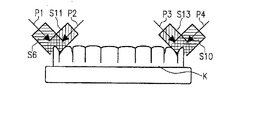
図1と図2では、顎Kの走査が、平面図と正面図で概略的に明示されている。例えば、五つの測定ストリップS1、S2、S3、S4及びS5が、隣り合って写像される。五つの測定ストリップS1〜S5は、図1aにおいて線影をつけて表され、図1bでは形態を分かり易くするために省略された領域Bにおいて部分的に重なり合う。ここで、図1bは、単に顎Kの正面図における測定ストリップS1〜S5の位置及び矢印Pによる走査光線の方向を明らかにするためだけに役立つものである。部分的に重なり合った領域Bは、マッチング方法により個々の測定ストリップのデータを組み合わせることで、顎Kの全体像を作ることを可能にする。 In FIG. 1 and FIG. 2, the scanning of the jaw K is schematically shown in plan and front views. For example, five measurement strips S1, S2, S3, S4 and S5 are mapped next to each other. The five measurement strips S1 to S5 are represented with line shadows in FIG. 1a and partially overlap in a region B which is omitted in FIG. Here, FIG. 1b serves only to clarify the position of the measuring strips S1 to S5 in the front view of the jaw K and the direction of the scanning beam by the arrow P. FIG. The partially overlapping region B makes it possible to create an overall image of the jaw K by combining the data of the individual measurement strips by a matching method.
図1cと図1dでは、WO 02/39056 A1による上述の技術のバリエーションが、同様に平面図と正面図で示されている。この方法及び対応する装置においては、単にいわゆるハーフフレームから成る測定ストリップS6、S7、S8、S9、S10、S11、S12及びS13が生成され、これにより、図1a及び図1bによるバリエーションに比べてより多くの測定ストリップが生成され、処理されることとなるが、しかしながら、これらの測定ストリップは明らかに少ないデータ量で扱われる。測定ストリップS6〜S13の位置は、図1cの平面図において、顎Kに関して表されている。照射方向は、一例として、図1dの測定ストリップS6、S11、S13及びS10に対して、矢印P1、P2、P3及びP4により概略的に示されている。図1cにおいては、各隣接する測定ストリップの部分的に重なり合った領域Bが、再び線影を付けて記入されている。個々の測定ストリップの照射方向が、先行技術に対して変更されていることにより、単にハーフフレームのみを使用し、先行技術に比べて少ないデータ量及び処理量で扱われるが、より詳細な顎Kのデータを得ることができる。 In FIGS. 1c and 1d, variations of the above-described technique according to WO 02/39056 A1 are likewise shown in plan and front views. In this method and corresponding apparatus, measuring strips S6, S7, S8, S9, S10, S11, S12 and S13, which are simply so-called half-frames, are generated, which is more than the variation according to FIGS. 1a and 1b. Many measurement strips will be generated and processed, however, these measurement strips are clearly handled with a small amount of data. The positions of the measuring strips S6 to S13 are represented with respect to the jaw K in the plan view of FIG. The irradiation direction is schematically indicated by arrows P1, P2, P3 and P4 as an example for the measurement strips S6, S11, S13 and S10 of FIG. In FIG. 1c, a partially overlapping region B of each adjacent measurement strip is again marked with a shadow. The irradiation direction of the individual measuring strips has been changed with respect to the prior art, so that only half frames are used and the amount of data and processing is reduced compared to the prior art, but a more detailed jaw K Data can be obtained.
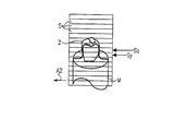
図2aでは、歯Zの形状を持つ個々の測定オブジェクトが、測定ポットM上に取り付けられているように、概略的に斜視図で示されている。ここで、測定オブジェクトを測定ポットM上に取り付けるために、測定ポットMは粘土で満たされており、ここに歯Zがその下方端(視認不可)で差し込まれる。 In FIG. 2 a, individual measurement objects having the shape of teeth Z are shown schematically in perspective view, as mounted on a measurement pot M. Here, in order to mount the measurement object on the measurement pot M, the measurement pot M is filled with clay, and the tooth Z is inserted here at its lower end (not visible).
図2c[正しくは:図2b]では、この測定オブジェクトZのために、測定ストリップ又は測定ラインSの位置が概略的に表されており、また図2cは、単に一つの測定地点Dxのみが得られる一つの測定ストリップ又は一つの測定ラインSxのためのシグナルグラフを示している。図2bでは、ほかに読み取り方向(ライン方向)が矢印A1で記入されている。例えばCCDチップ又はその他の各カメラ装置により構成され得る画像写像装置としてのチップCは、全ての測定ストリップ又は測定ラインSの総和により形成される。 In FIG. 2c [Correctly: FIG. 2b], for this measurement object Z, the position of the measurement strip or measurement line S is schematically represented, and FIG. 2c shows only one measurement point Dx. 2 shows a signal graph for one measurement strip or one measurement line Sx. In FIG. 2b, the reading direction (line direction) is additionally indicated by an arrow A1. For example, a chip C as an image mapping device which can be constituted by a CCD chip or other camera devices is formed by the sum of all measurement strips or measurement lines S.
WO 02/39056 A1による一つの測定ストリップ又は一つの測定ラインにおいては、図2bと2cに類似した表現で示されている図2dと2eが明示しているように、例えばDy1とDy2又はDzaからDznのような多数の測定地点が得られる。そこでは、読み取り方向は、図2dにおける矢印A2に従い、またチップC並びに測定ストリップ又は測定ラインSの位置は、上述の先行技術に対して90度回転している。この配置によって、測定ラインSyでは、二つの測定地点Dy1とDy2が得られる。測定ラインSzでの測定においては、多数の測定地点Dza〜Dznでさえも得られる。それから、評価するために、とりわけソフトウェアによって、先行技術の場合と同じような(図2b参照)チップ配列が再演算され、シミュレートされる。それによって、先行技術と同様の読み取り方向においては、配列又はライン毎に、初めに地点1、次に地点2等々というように、計算上得ることのできる多くの測定地点が含まれることとなる。このWO 02/39056 A1による知見では、単にハーフフレームのみを用いることによる僅かな消費で、非常に多くの情報が得られ、このため精度はWO 02/39056 A1を通じ、従来の先行技術に比べてさらに上昇する。
In one measuring strip or one measuring line according to WO 02/39056 A1, for example from Dy1 and Dy2 or Dza, as shown in FIGS. 2d and 2e, which are shown in a representation similar to FIGS. 2b and 2c, A large number of measurement points such as Dzn are obtained. There, the reading direction follows the arrow A2 in FIG. 2d, and the position of the tip C and the measuring strip or measuring line S is rotated by 90 degrees with respect to the prior art described above. With this arrangement, two measurement points Dy1 and Dy2 are obtained in the measurement line Sy. In the measurement on the measurement line Sz, even a large number of measurement points Dza to Dzn are obtained. Then, for evaluation, a chip array similar to that of the prior art (see FIG. 2b) is recomputed and simulated, especially by software. As a result, in the same reading direction as in the prior art, each array or line includes many measurement points that can be calculated, such as
図3とその部分拡大図である図4においては、レーザー光線Lが発射されるレーザー光学機器4を備えた表面写像装置1が示されている。オブジェクトを起点とした矩形のビューフィールドF[正しくは:H]とレーザー光線Lとの交点により、測定フィールドFが規定される。測定される各オブジェクトは、この測定フィールドFを通過することとなる。この詳細は、たとえその他の特徴を表す目的でそこにそれ以上示されていないとしても、図5、6と7による形態に対して有効である。記述の反復を回避するという点で、下記の図5、6と7を取り扱う際においては、そのことについてそれ以上言及しなくとも、この技術がそこで適用可能であることは、当業者により当然に認識され、また理解され得る。
In FIG. 3 and FIG. 4, which is a partially enlarged view thereof, a
以下では、形態が同一又は比較可能である限りにおいて、記述の反復を回避するために図5、6及び7も引用される。 In the following, FIGS. 5, 6 and 7 are also cited to avoid repetition of the description as long as the forms are identical or comparable.
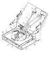
測定フィールドFの「通過」は、リニアガイド83(又は、図5と6における引用符号4’)により行われる。とりわけ歯のような複数の個々のオブジェクトを測定フィールドFに位置決め可能とするために、回転プレート33(又は、図5、6及び7における引用符号5)は各測定ポット84の移送が可能となるように回転する。(図5においては、測定ポットは引用符号8で記される。)。図3においては、一例として、単に二つだけの測定ポット84が示されているが(図5において、例えば、単に二つの測定ポット8が示されているのと同様に)、例えば全部合わせて七個が取り付け可能である。
The “passing” of the measurement field F is performed by the linear guide 83 (or
歯が備え付けられた測定ポット84(又は、図5における8)が測定フィールドFに到着すると、大きな回転プレート33(又は、図5、6及び7における5)の回転が停止する。従って、回転プレート33(又は、図5、6及び7における5)は、個々の歯が備え付けられたポット84(又は、図5における8)及び/又は下記に論じられる顎の位置決めをするためだけに利用される。測定は、上記に詳述したように、リニアベアリング83又は4’(図5における)上での測定テーブル53の直線移動によって行われる。
When the measuring pot 84 (or 8 in FIG. 5) equipped with teeth arrives at the measuring field F, the rotation of the large rotating plate 33 (or 5 in FIGS. 5, 6 and 7) stops. Thus, the rotating plate 33 (or 5 in FIGS. 5, 6 and 7) is only for positioning the pot 84 (or 8 in FIG. 5) with individual teeth and / or the jaws discussed below. Used for The measurement is performed by linear movement of the measurement table 53 on the
その移動の結果として、測定される歯の一側面だけを臨む測定ストリップが生じる。その他の視角からその他の測定ストリップを取得可能とするために、測定領域に在るポット84(又は、図5における8)は、個々の測定の間に自身の軸の周りを回転することができる。これは、例えばポット84(又は、図5における8)が各測定の間に自身の軸の周りを夫々45度ずつ自転するのであれば、八つの観察点が得られることとなる。従って、そのような場合では、異なった観察点から八つの測定ストリップが生じる。得られた表面情報の一部は、いくつかの測定ストリップにおいて見られる。これらの部分的に重なった領域を用いることにより、例えば上記に詳述したマッチング・ソフトウェアの形式による適切な装置又は方法を用いて、個々の測定ストリップの合成により、完全な個々の歯の三次元表面画像を、高い測定精度で生成することができる。 As a result of the movement, a measuring strip is produced which faces only one side of the tooth to be measured. In order to be able to obtain other measurement strips from other viewing angles, the pot 84 (or 8 in FIG. 5) in the measurement region can rotate around its own axis during individual measurements. . For example, if the pot 84 (or 8 in FIG. 5) rotates 45 degrees around its own axis during each measurement, eight observation points are obtained. Thus, in such a case, eight measurement strips are generated from different observation points. Some of the surface information obtained can be found in several measurement strips. By using these partially overlapping areas, a complete individual tooth three-dimensional, for example by synthesis of individual measurement strips, using an appropriate device or method in the form of the matching software detailed above. A surface image can be generated with high measurement accuracy.
これらのデータによって、ここですでに、歯冠の内部データレコードを研削加工することができる。この個々の歯冠の研削に加えて、複数の個々の歯もブリッジにまとめることができる。ブリッジを研削可能とするために、複数の個々の歯冠の空間的な位置が、互いに相対して、できるだけ迅速に把握されなければならない。そのために、個々の歯と同じようにして、顎モデルが測定される。このため顎モデルは、図5での回転プレート5内に設けられた追加の回転プレート26上に置かれる。
With these data, the internal data record of the crown can already be ground here. In addition to this individual crown grinding, a plurality of individual teeth can also be combined into a bridge. In order to be able to grind the bridge, the spatial position of a plurality of individual crowns must be known as quickly as possible relative to each other. For this purpose, the jaw model is measured in the same way as for individual teeth. For this purpose, the jaw model is placed on an additional
その結果は、図8の画像において見ることができる。測定ストリップの方向は、五つの白い線(符号I1、I2とI3が付けられ、残りは単に線のみで記されている。)として認識され得る。この測定結果には、全ての顎のデータが含まれていないが、しかしながら、個々の残根のデータを用いてこれを自動的に作成可能とするだけの、十分に多くのデータが含まれている。 The result can be seen in the image of FIG. The direction of the measuring strip can be recognized as five white lines (labeled I1, I2 and I3, the rest are simply marked with lines). This measurement does not include all jaw data, however, it contains enough data to make it possible to automatically create it using individual residual root data. Yes.
その後で、データを照合する検索ソフトウェアが、適切な装置又は方法を伴って始動する。その結果は、図9の画像で示される。このデータレコードは、顎モデルにおける左上の第一の歯及びその次の間隙の後の歯の、両方が明瞭となっているものであって、参照された個々の歯を表している。 Thereafter, the search software that collates the data is started with the appropriate device or method. The result is shown in the image of FIG. This data record is clear of both the upper left first tooth in the jaw model and the tooth after the next gap, representing the referenced individual tooth.
以下では、その他の改善点が表現及び詳述される。 In the following, other improvements are expressed and detailed.
平面から視た斜視図である図5並びに同一の装置の底面から視た斜視図を示す図6及び図7に関して、回転プレート5は、個々の歯のための異なった測定ポット8を、レーザー測定位置(図3参照)に移動させるために役に立つ。この回転プレート5は、摩擦ホイール15(図6参照)により動かされる。この摩擦ホイール15は、スプリングプレート24(図6参照)により、前面を回転プレート5に押しつけられる。これにより、摩擦ホイール15のゴム表面又はゴム材料は均等に摩耗する。
With reference to FIG. 5 which is a perspective view seen from the plane and FIGS. 6 and 7 which show a perspective view seen from the bottom of the same device, the
回転プレート5の位置は、エンコーダディスク28によって定められる。この場合にあっては、ディスクは、必要な停止位置を正確に位置決めするためのスリット100を備えた金属板28(図6参照)により構成される。スリット100は、光バリアー装置33(図6参照)により検出される。制御ソフトウェアは、適切な装置又は方法に従って、光遮断シグナルを評価し、テーブル又はプレート5を始動/停止させる。回転プレート5は、個々の歯のための七つの位置/ポットを備えている。作業が七つ以上のプレパレーション/歯となる場合には(最多で顎当り14つが可能である。)、作業は2バッチで走査され得る。
The position of the
上記に詳述した装置の利点;
−非常に有利な製造費用
−どこでも使用可能であること
−摩耗がないこと
−静かな作動
−正確な位置の知識
Advantages of the device detailed above;
-Very advantageous production costs-Can be used everywhere-No wear-Quiet operation-Accurate location knowledge
摩擦ホイール15の代替として、例えばベルトプーリー又は歯状ベルトも用いることができる。
As an alternative to the
その他の措置により、外枠構造の値下げもさらに達成され得る。そのために、機器/装置の外枠は、二つのガイドロッド83(図3及び4参照)上に置かれる。従って、機器の完全な外枠は、単に二つの側面部分2(図3及び4参照)、ガイドロッド83(図3及び4参照)並びに光学プレート(図5)のみから構成される。機械を用いてリニアロッドガイドを製造することによって生じる不正確さは、ソフトウェア(例えば、いわゆる「検査テーブル」による)により調整される。精密スピンドル94(図3及び4参照)は、移動テーブルのレーザー配置のある側面に取り付けられている。それにより、スピンドルの角度誤差の影響は減少する。この形態例の利点は、安価な製造コスト、高い精度、非常に軽少な輸送重量及びより小型の構造にある。 By other measures, the price reduction of the outer frame structure can be further achieved. For this purpose, the outer frame of the device / device is placed on two guide rods 83 (see FIGS. 3 and 4). Thus, the complete outer frame of the device consists solely of two side portions 2 (see FIGS. 3 and 4), a guide rod 83 (see FIGS. 3 and 4) and an optical plate (FIG. 5). Inaccuracies caused by manufacturing a linear rod guide using a machine are adjusted by software (eg, via a so-called “test table”). A precision spindle 94 (see FIGS. 3 and 4) is mounted on the side of the moving table where the laser is located. Thereby, the influence of the spindle angle error is reduced. The advantages of this embodiment are low manufacturing costs, high accuracy, very light transport weight and a smaller structure.
WO 02/39056 A1以前の先行技術に対するその他の改善点は、レーザーダイオードの電気的な保護のためになされ得る。そのために、レーザー光学機器、レーザーダイオード及びレーザーダイオード用の駆動電子機器は、一緒に金属ケース内に収納されている。このことから、とりわけ外側からの静電気チャージに対するダイオードのより良い保護、及び、修理における迅速な交換が、利点として生み出される。 Other improvements over prior art prior to WO 02/39056 A1 can be made for electrical protection of the laser diode. For this purpose, the laser optical device, the laser diode and the driving electronics for the laser diode are housed together in a metal case. From this, better protection of the diode, especially against external electrostatic charges, and quick replacement in repairs are produced as advantages.
さらに、先行技術に対するWO 02/39056 A1により、顎モデルを調節する際の改善が可能である。測定される顎モデルを最適に調節可能とするために、テンプレート54(図5参照)が必要である。顎モデルには様々な直径のものがあるため(例えば、子供や大人のための)、その大きさに応じて合わせなければならない。この目的のために、例えば三つの異なった調節輪郭I、II及びIIIが、テンプレート54が好適に形成される透明なプレキシガラスディスクに彫り込まれるか、又はほかに適切に塗装される。
In addition, WO 02/39056 A1 over the prior art allows improvements in adjusting the jaw model. In order to be able to adjust the jaw model to be measured optimally, a template 54 (see FIG. 5) is required. There are jaw models of various diameters (for example, for children and adults), so they must be adjusted according to their size. For this purpose, for example, three different adjustment contours I, II and III are engraved on the transparent plexiglass disc on which the
そのほかさらに、個々のポットが例えば45度ずつ回転する際に、その他の改善が達成され得る。回転プレート5(図5、6及び7)は、個々の測定ポット8を摩擦ホイール15前の測定位置に運ぶ。回転プレート5が回転している間は、摩擦ホイール15へのポット8の摩擦接触が自動的に生み出される。特筆すべき点は、反対ホイール7が全て金属から成るにもかかわらず、摩擦ホイール15がゴムから成るか、又は少なくともゴムの回転表面を有していることである。これには、より少ないコスト、より容易な製造並びに長い耐用年数という利点がある。
In addition, other improvements can be achieved when the individual pots are rotated, for example, by 45 degrees. The rotating plate 5 (FIGS. 5, 6 and 7) carries the
WO 02/39056 A1のその他の知見が、図10により説明される。この図では、夫々研削された部分101aと歯の残留領域101bから成る三つの残根が示されている。研削は歯科医によって手で行われ、必然的に、複数の隣り合って並んだ個々の歯及びその残根101の観察において形状、位置及び大きさが異なったものとなる、アンダーカット102が生じる。
Other findings of WO 02/39056 A1 are illustrated by FIG. In this figure, three residual roots , each consisting of a
図10の左側に示された残根101において破線で表されている設計されたプロテーゼ103を、残根上に組み付けるために、まず第一に、少なくとも一つの残根101のために、矢印Eによる挿入又は取付方向で正確に残根101の上方へ押し入れられ得る、いわゆるキャップ104が製造される。キャップ104を残根101上に押し入れる際には、その他の押し付けがそれ以上できなくなることから、キャップ104がアンダーカット102を満たすことは不可能となる。本実施例の場合にあっては、三つの残根101が隣り合って並んでおり、夫々隣接したキャップ104を夫々ウェブ105を用いて繋ぎ合せることによって、当該の三つのキャップ104が一つのブリッジにまとめられる。
In order to assemble the designed
全てのキャップ104を全体として設計する際には、ここで、図10において右側の残根101で示されているように、例えばその他の残根101に関して一つの残根101が傾いた状態であることによっても形成されるアンダーカット102を最小限に抑える、最適な挿入又は取付方向が算定されなければならない。
When all the
このことは、残根101から得られた三次元データを用いて、前もって演算することが可能である。そのためには、本明細書で既に詳述されているように、三次元データレコードが、WO 02/39056 A1によるスキャンによって生成され、この三次元データレコードが最適な挿入又は取付方向を算出するためのモデル演算のために利用される。WO 02/39056の方法によるこの知見では、順に異なった押付方向が基礎として用いられ、夫々の演算結果に対して、アンダーカット102に起因する「デッドスペース」が算出される。最適な挿入方向Aは、最も小さな「デッドスペース」を持つバリエーションが決定されることによって得られる。
This can be calculated in advance using the three-dimensional data obtained from the remaining
とりわけ残りの残根101の傾斜状態によるが、歯科医による処置の不正確さによっても、歯の残留領域101bとの関係で、キャップが、所々で0mmの壁厚を持たなければならない場合を生じる。そのような場合においては、原則的にプロテーゼを製造することが不可能である。さらなる処置のためには、まず最初に、作業が有益な結果に結びつくかが不確かな、時間及び費用のかかる当該の残根101の再処置を行わなければならない。
In particular, depending on the inclination state of the remaining
アンダーカット又は「デッドスペース」102を最小限に抑えるためのWO 02/39056 A1による挿入方向Eの最適化に加えて、WO 02/39056 A1は、プロテーゼを製造するための処置方法をさらに改善するために利用することができる。写像された(スキャンされた)三次元データを用いることにより、アンダーカット又は「デッドスペース」102の顕著な減少及び製造されるプロテーゼのフィットと安定性の改善を、より容易にもたらす残根の再処置手段を、担当歯科医に推奨することができる。そのためには、WO 02/39056 A1による方法の有効範囲が、一つの残根101又は複数の残根101の組み合わせが写像された三次元データレコードに関して、残根/複数の残根の形状が変更可能であるという条件のもとで、キャップ104、とりわけブリッジ106となるように繋ぎ合わされた複数のキャップ104のための最適な取付方向が演算される、という範囲に及ぶこととなる。それにより、WO 02/39056 A1による方法及びシステムは、キャップ104又はブリッジ106の製造及び取り付けのための目下の状況への調整を算定するためだけでなく、プロテーゼを最適化するために目下の状況を変更するためにも役に立つ。この方法及びシステムにおいては、例えば、再処置のための特別に色付けされた領域を有する残根を表示し、歯科研究所と歯科医との間での対話の基礎として活用されるグラフィックディスプレイが含まれていることが提案されている。
In addition to optimizing insertion direction E with WO 02/39056 A1 to minimize undercuts or “dead space” 102, WO 02/39056 A1 further improves the treatment method for manufacturing prostheses Can be used for. By using the mapped (scanned) 3D data, the residual roots can be re- created more easily resulting in a significant reduction in undercuts or “dead space” 102 and improved prosthesis fit and stability. Treatment measures can be recommended to the attending dentist. To that end, the effective range of the method according to WO 02/39056 A1 changes the shape of the residual root / multiple residual roots with respect to a three-dimensional data record in which one
そのほかさらに、上述した特徴を備えるWO 02/39056 A1により、とりわけ処置結果を、残根を適切に研削する歯科医に、又はキャップ/歯冠/ブリッジを作成する歯科研究所に明確に分類することを含む、品質保証の可能性が好適につくり出される。それにより、不正確なフィットの場合に誰が責任を負うかという問題を、初めて明らかにすることが可能となる。そのほかさらに、その際には、あらゆる初期データ及び状態間のデータを欠陥なしに極めて容易に、及び、いつでも繰り返しアクセス可能にデータ保管できることが、好適に利用され得る。 In addition, according to WO 02/39056 A1 with the above-mentioned features, in particular the treatment results can be clearly classified to the dentist who properly grinds the residual root or to the dental laboratory which creates the cap / crown / bridge The possibility of quality assurance including is preferably created. This makes it possible for the first time to reveal the question of who is responsible for an inaccurate fit. In addition, in that case, it can be preferably used that all initial data and data between states can be stored very easily without any defects and repeatedly accessible at any time.
図10に関して上述された方法及びそのバリエーションは、これらの方法を実行可能にする相応に組み立てられた装置と同等であり、そのため、その一般及び特別の特徴における方法の説明から、当業者が容易かつ即座に理解されるような装置も、本明細書において開示されていると見なされる。 The methods described above with respect to FIG. 10 and variations thereof are equivalent to correspondingly assembled devices that enable these methods to be performed, so that those skilled in the art will be able to easily and from the description of the method in its general and special features. Devices that are readily understood are also considered disclosed herein.
WO 02/39056 A1のその他の知見は、反対咬合(上顎から下顎へ)を考慮したプロテーゼの噛合面の自動生成に関する。図11及び12で明らかにされた実施例では、以下に説明されるステップが提案されている。:
[1.]
咬合状況がシミュレートされるまでの、上顎206と下顎207の調整ジョイント201を備えた噛合シミュレータ又は咬合機200へのはめ込み及び調節(図11による)。上顎206と下顎207の支持盤202/202aと203/203aは、検出可能な空間的位置を持っている。さらに、支持盤202/202aと203/203aは、例えば夫々定義されたゼロ位置又は互いに相対するゼロ位置を持っている。各支持盤202/202aと203/203aは、二つの部分から成り、夫々、咬合機200に固定して設けられる支持基盤202a又は203a、及び夫々に上顎206又は下顎207が取り付けられる顎支持盤202又は203から構成されている。
[2.]
例えば六つの自由度の読み取り/記録:
二つの可能性:−目盛りの手動の読み取り
−測定センサの読み取り
咬合機200により、支持盤202/202aと203/203a、すなわち実際には夫々支持基盤202a又は203aの最適な/正しい姿勢が、上顎206と下顎207を考慮して演算される(図11による)。これは、そのために咬合機200に付設された目盛り(図示省略)により、又は位相角センサ(図支省略)により自動的に行われる。なお、注意すべきことは、咬合機200が六つの自由度で互いに相対した上顎206と下顎207の調整を好適に可能とすることである。
[3.]
支持盤205の空間的位置が測定システムに対して又はスキャナーのデータシステムに既知である際の、上顎モデル206又は下顎モデル207を備えた相応の顎支持盤202又は203の、支持基盤202aと203aに類似したスキャナーの支持盤205へのはめ込み(図12による)。
[4.]
それから、ソフトウェアにより参照づけが行われる。
[5.]
−データバンクからの噛合面(例えば、切歯)のための提案
−反対咬合状況へのデータバンクモデルの自動調整
−カバーデータでの接触地点の検索
−噛合面と内部データの組み合わせ
Other findings of WO 02/39056 A1 relate to the automatic generation of the occlusal surface of the prosthesis taking into account the opposite occlusion (upper jaw to lower jaw). In the embodiment disclosed in FIGS. 11 and 12, the steps described below are proposed. :
[1. ]
Fitting and adjustment of the
[2. ]
For example, reading / recording six degrees of freedom:
Two possibilities:-manual reading of the scale
-Reading of the measuring sensor The
[3. ]
Support bases 202a and 203a of a corresponding
[4. ]
Then, referencing is performed by software.
[5. ]
-Proposals for mating surfaces (eg, incisors) from the data bank-Automatic adjustment of the data bank model to the opposite occlusion situation-Search for contact points in the cover data-Combination of the mating surface and internal data
代替として:明瞭に表現された顎の部分のスキャンと、咬合姿勢を生成するためのこの部分データレコードを用いたその後の上顎と下顎のマッチングによる、顎姿勢の「明確に表現された」検出。 Alternative: “Clearly expressed” detection of jaw posture by scanning a clearly expressed jaw part and then matching the upper and lower jaws using this partial data record to generate an occlusal posture.
図11と12に関して上述されたWO 02/39056 A1の知見も、当業者が上記の説明に基づいて一般又は特別の特徴における適切な装置を容易に判別することから、方法及び装置に関して開示されていると判断される。 The knowledge of WO 02/39056 A1 described above with respect to FIGS. 11 and 12 is also disclosed with respect to the method and apparatus since those skilled in the art will readily determine the appropriate apparatus in general or special features based on the above description. It is judged that
本発明は、記述及び表現が、一例として当業者に簡単に理解されるように、夫々の知見に関してより詳細に、以下のように説明される。さらに、当業者は、特別の説明無しで、既述及び図面に表され、同様に本明細書の発明の重要な開示内容の一部をなすものである先行技術を総覧して、有利性のある組み合わせ並びに細部の設計及び作用を知得することとなる。そのほかに、本発明による装置と方法の類似性は、同じ目的のために役立つ装置及び方法のための夫々別々の記述及び表現が必要とされずに、全文章内容から当業者に明らかになる。しかしながら、後述された本発明の個々の知見は、とりわけ上述した先行技術、特にWO 02/39056 A1と強制的に組み合わされずに、その他の各適切な技術とも置き換えられ得るということが重要である。従って、機械による走査、その他の光学的走査システム及びその方法を使用した表面写像技術並びにその他の各適切な走査技術は、本発明の個々の知見と組み合わせることができる。とりわけ義歯部品の造形に関係する材料加工のためには、研削技術の他に、例えば鋳造技術、レーザー焼結等々のような別の技術も本発明の個々の知見に関して利用することができる。 The present invention is described in more detail below with respect to their respective findings, so that the description and representation will be readily understood by those skilled in the art by way of example. Further, those skilled in the art will be able to review the prior art which is represented in the description and drawings without special explanation, and which also forms part of the important disclosure of the invention of this specification. One knows the combination and details of the design and operation. In addition, the similarities between the apparatus and method according to the present invention will become apparent to those skilled in the art from the full textual content without requiring separate descriptions and expressions for the apparatus and method which serve the same purpose. However, it is important that the individual findings of the present invention described below can be replaced notably with the prior art described above, in particular with WO 02/39056 A1, but with each other suitable technique. Accordingly, mechanical scanning, other optical scanning systems and surface mapping techniques using the method, and each other suitable scanning technique can be combined with the individual findings of the present invention. In particular, for material processing related to the shaping of denture parts, in addition to grinding techniques, other techniques such as casting techniques, laser sintering etc. can also be used in connection with the individual findings of the invention.
本発明によれば、その最初の知見において、とりわけ部分又は全自動によるインレープレパレーションの境界判定のためと、さらに引き続いて義歯部品としてインレーを製造するための装置及び方法が提案されている。これに関する装置は、下記の説明とそこで示された図面の図から当業者に容易に明らかとなる。 According to the present invention, in its first knowledge, an apparatus and a method for determining the boundary of an inlay preparation, in particular partially or fully automatically, and subsequently for producing an inlay as a denture part have been proposed. The apparatus in this regard will be readily apparent to those skilled in the art from the following description and the drawings shown therein.
上述の義歯部品つまりインレーの、CAD/CAM方法による製造においては(類似したその他の義歯部品が全く同じようにカバーされる)、インレーのために歯科医によって準備された残根の三次元表面データレコードを、ソフトウェアを用いて、製造されるインレーと残りの歯の物質の間の境界が走る場所が自動的に判定されるように解析するということに、とりわけ困難性がある。図13と14の比較から明らかであるように、プレパレーションの鋭角な境界は、インレープレパレーションに特有である。以下に記述された発明に応じた方法、並びに、その方法から当業者に容易に明らかとなる相応の装置は、この境界の自動的な判定と切離しを内容として含んでいる。 In the manufacture of the above-mentioned denture parts or inlays by CAD / CAM method (other similar denture parts are covered in exactly the same way), residual root three-dimensional surface data prepared by the dentist for the inlay There are particular difficulties in analyzing the records using software to automatically determine where the boundary between the manufactured inlay and the remaining dental material runs. As is apparent from a comparison of FIGS. 13 and 14, the sharp boundary of the preparation is unique to inlay preparation. The method according to the invention described below, and the corresponding device that will be readily apparent to those skilled in the art, include the automatic determination and separation of this boundary.
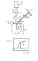
すでに、WO 02/39056 A1又はDE 19721688 A1による先行技術のような例えばレーザーを用いた測定方法においては、評価されるカメラチップ上の光シグナルは、上述した方法のための本質的な情報を含んでいる。:図13に示されているように、レーザー線が窩縁を含まない表面部分に接している間は、レーザー光線の全ての幅が反射される。図13では、レーザー光源LQからの光線幅LBを有するレーザー光線LSが衝突する歯の表面を備えた歯Zが示されている。反射した光線RSは、その際に幅LBR1を有し、この幅で検出装置としてのCCDチップCCDに衝突する。しかしながら、図14から見て取れるように、レーザー光線LSが窩縁に衝突する場合では、僅かにレーザー光線LSの幅LBS2の部分だけが、反射した光線RSとしてCCDチップCCDへ反射される。例えば、窩縁Kで反射した光線RSの幅LBS2は、窩縁を含まない表面部分での反射状況に関して、対応するシグナル図が夫々図13と14の下半分に示されているように、LBR2=1/2LBR1である。これに関するシグナル図がまた夫々図13と14の下半分に示されているように、評価されるシグナルの波形は全く同じように変化する。:表面(図13参照)においては対称的なガウス曲線が表され、窩縁の領域においては、表面の走査に起因する(図13の場合に類似)シグナル1、表面で穴の境界に到達した際に得られるシグナル2、及び、直接に穴の境界で又はとりわけ表面の窩洞ZKで得られる(図14の場合に類似)シグナル3のシグナル波形が概略的に示された図15で見られるように、シグナルは非対称的に推移する。幅の変化とシグナル波形からの情報は、窩縁Kの実際の境界を最適に算定するために処理することができる。上述した方法を用いて様々な立体角からこの窩縁Kを何度も測定することによって、これらの情報は、マッチング方法を用いて相互に調査し、窩縁領域で平均化することによりその最終的な形で決定することができる。
Already in measuring methods using eg lasers, such as prior art according to WO 02/39056 A1 or DE 19721688 A1, the light signal on the camera chip to be evaluated contains essential information for the method described above. It is out. : As shown in FIG. 13, the entire width of the laser beam is reflected while the laser line is in contact with the surface portion that does not include the fossa edge. FIG. 13 shows a tooth Z having a tooth surface on which a laser beam LS having a light beam width LB from the laser light source LQ collides. The reflected ray RS has a width LBR1 at that time, and collides with a CCD chip CCD as a detection device with this width. However, as can be seen from FIG. 14, in the case where the laser beam LS collides with the fossa edge, only a part of the width LBS2 of the laser beam LS is reflected to the CCD chip CCD as the reflected beam RS. For example, the width LBS2 of the ray RS reflected at the fossa K is related to the reflection situation at the surface portion not including the fossa, as shown in the corresponding signal diagrams in the lower half of FIGS. 13 and 14, respectively. = 1/2 LBR1. As the signal diagram for this is also shown in the lower half of FIGS. 13 and 14, respectively, the waveform of the signal to be evaluated varies in exactly the same way. : Symmetrical Gaussian curves are represented on the surface (see Fig. 13), and in the region of the fossa, signal 1 due to scanning of the surface (similar to the case in Fig. 13)
この方法によりスキャンされた、その三次元データレコードが例えば適切な表面三角測量方法によりさらに処理されたインレーの窩洞の三次元データレコードは、特徴として、少なくとも三つ以上の頂点により表現される表面を含んでいる。これらの表面は、図16のグラフィックが具体的に示されているように、共通の窩縁又は地点により繋がれている。部分又は全自動による境界判定と切離しのための上述の方法は、ここで、プレパレ−ションの境界が平均以上の強い曲率又は角度を示すという演繹的な情報により行われる。 A 3D data record of an inlay cavity that has been scanned by this method and whose 3D data record has been further processed, for example, by a suitable surface triangulation method, is characterized by a surface represented by at least three or more vertices. Contains. These surfaces are connected by a common fossa edge or point, as specifically illustrated in the graphic of FIG. The above-described method for partial or fully automatic boundary determination and separation is now performed with a priori information that the boundary of the preparation exhibits a strong curvature or angle above average.
ここで表面データレコードの全ての地点において、平均的な地点標準部位(ノーマル)が全ての隣接している表面データレコードから演算されれば、その後に表面データレコードの標準部位から地点標準部位を相違解析することにより、曲率値が決定され得る。次のステップでは、隣接関係を見つけることによって、様々な判断基準に関する値を増やし、分類する。この判断基準により、例えば繋がっているラインに関する隣接関係を築くことが可能である。それにより、自動的な窩縁判定のための基礎土台が築かれている。 Here, if the average point standard part (normal) is calculated from all adjacent surface data records at all points in the surface data record, then the point standard part is different from the standard part of the surface data record. By analyzing, the curvature value can be determined. The next step is to increase and classify values for various criteria by finding adjacencies. Based on this criterion, for example, it is possible to establish an adjacency relationship regarding connected lines. As a result, a basic foundation for automatic rim determination is laid.
ソフトウェアによって、窩縁はここで最適に分析、判定され、そして、図17と18の方法ステップ図で概略的に示されているように、一本の連続した窩縁線に繋ぎ合わされる。その後のインレーの製造には、窩縁線内側にある表面セグメントだけが活用される。 By means of the software, the fossils are optimally analyzed and determined here and joined to a single continuous fossa line as schematically shown in the method step diagrams of FIGS. Only the surface segments inside the foveal line are utilized for subsequent inlay manufacturing.
図17の(1.)では、インレー用に準備された歯の窩洞ZK及びその境界若しくは窩縁Kを有する残根プレパレーションSPのデータレコードが、実際では全体として三次元データレコード、つまり残根プレパレーションの三次元データによる表現が問題となるが、簡略化のために単に側面図で概略的に示されている。 In (1.) of FIG. 17, the data record of the tooth cavity ZK prepared for the inlay and the residual root preparation SP having the boundary or the peripheral edge K is actually a three-dimensional data record, that is, the residual root. Although the representation of the preparation by three-dimensional data is a problem, it is schematically shown in a side view for simplicity.
図17の(2.)では、境界又は窩縁Kの判定と切離しのステップが単に概略的に図示されており、ここでは、ステップ(1.)からの三次元データレコードが再び二次元の表現で表されている。その際に、窩縁の検出は、例えば図13から図16について詳述され、それらの図に示されているようにして行われる。 In FIG. 17 (2), the step of determining and separating the boundary or fossa K is schematically illustrated, where the 3D data record from step (1.) is again represented in 2D. It is represented by In doing so, the detection of the fossa edge is performed as described in detail in FIGS. 13 to 16, for example.
さらに、図18では、ステップ(3.)が、簡略化のために完全な三次元データレコードを二次元的な表現として、概略的に図示されている。ここでは、例えばデータバンク−噛合面KFをインポートすることにより、製造される後のインレーの欠けている面が、他の点に関してインレーの形状と寸法を定める準備された歯の窩洞ZKデータに付加えられる。このステップでは、例えばデータバンクに蓄積された噛合面データ(例えば、下顎の第四番目の臼歯に対する)が全データレコードにインポートされるか、あるいは、歯科医による処置前に測定された本来の歯のデータ又は歯科技巧士によりインレー用に個別にワックス内でモデル化された噛合面がインポートされる。 Further, in FIG. 18, step (3.) is schematically illustrated as a two-dimensional representation of a complete three-dimensional data record for simplicity. Here, for example, by importing the data bank-mating surface KF, the missing surface of the inlay after it is manufactured is attached to the prepared tooth cavity ZK data that defines the shape and dimensions of the inlay with respect to other points. Added. In this step, for example, the occlusal surface data stored in the data bank (for example, for the fourth molar of the lower jaw) is imported into all data records, or the original tooth measured before treatment by the dentist. Or meshing surfaces individually modeled in wax for inlays by a dental technician.
図18の(4.)は、噛合面KFと歯の窩洞ZKの夫々の三次元データレコードの代わりに二次元の概略図が示されており、このステップでは、インポートされた噛合面KFのデータが準備された歯の窩洞ZKに結び合わされる。噛合面データは、例えばマッチングアルゴリズムによる自動的な調整機能により、最適に境界に合わせられ、境界上に配置される。 FIG. 18 (4) shows a two-dimensional schematic diagram instead of the respective three-dimensional data records of the meshing surface KF and the tooth cavity ZK. In this step, the imported meshing surface KF data is shown. Are tied to the prepared tooth cavity ZK. The meshing surface data is optimally aligned with the boundary by, for example, an automatic adjustment function using a matching algorithm, and is arranged on the boundary.
最後に、図18のステップ(5.)では、噛合面のモーフィングと余剰分の切り取りが行われ、これにより、完成したインレーデータレコードISが得られる。このインレーデータレコードISは、簡略化のために、完全な三次元データを備える実際のデータレコードに対する単なる二次元的な表現として示されている。噛合面は、例えばモーフィングによって反対咬合に適合させることができる。得られた三次元データレコードは、インレー部分のCNC製造のために活用することができる。その際には、研削工具FWでの研削工程終了後に残っているインレーIの処理ウェブHSが、図19で図示されているように噛合面KFの領域に位置すれば、インレーIの精度にとってとりわけ有利である。 Finally, in step (5.) of FIG. 18, the meshing surface morphing and cutting off the surplus are performed, whereby a completed inlay data record IS is obtained. This inlay data record IS is shown as a simple two-dimensional representation for real data records with complete three-dimensional data for simplicity. The mating surface can be adapted to the opposite occlusion, for example by morphing. The obtained three-dimensional data record can be used for CNC production of the inlay portion. In that case, if the processing web HS of the inlay I remaining after the grinding process with the grinding tool FW is located in the region of the meshing surface KF as shown in FIG. It is advantageous.
発明の第二の知見では、とりわけ複雑な義歯設計物を製造するための方法を生み出している。これに関する装置は、後述の説明とそこで示された図面から当業者に容易に明らかになる。 The second finding of the invention has created a method for producing particularly complex denture designs. The apparatus in this regard will be readily apparent to those skilled in the art from the following description and the drawings shown therein.
従来の歯科技術においては、組み立て式の部品が頻繁に用いられている。そこでは、例えばインプラント支柱、アバットメント及びアタッチメント部品が、機械によって従来の義歯と繋ぎ合わされている。 In conventional dental technology, prefabricated parts are frequently used. There, for example, implant struts, abutments and attachment parts are joined to a conventional denture by a machine.
本発明は、複数の組み立て式部品の、例えば接着剤による組み合わせ工程を除去することを可能とする。金銭面に加えて、患者のためのより優れた健康両立性も、単に一つの材料だけが体内に挿入されることから成し遂げられる。さらに、より長い耐用年数とより高い全体精度が可能となる。 The present invention makes it possible to eliminate the process of combining a plurality of prefabricated parts, for example with an adhesive. In addition to the financial aspects, better health compatibility for the patient is also achieved by simply inserting one material into the body. Furthermore, a longer service life and higher overall accuracy are possible.
ここで扱われる発明の知見の好ましい構成は、組み立て式の義歯部品又は設計構成要素の三次元CAD設計データ、あるいは、義歯部品の結合構成要素と、残根及び/又は歯の形状(以前の表面)の三次元測定データが合わされることにある。 The preferred configuration of the knowledge of the invention addressed here is the three-dimensional CAD design data of a prefabricated denture part or design component or the combined component of a denture part and the residual root and / or tooth shape (former surface ) 3D measurement data is to be combined.
図20aは、一例として従来の完成品の状況を示しており、図20bは、本発明による完成品の状況を示している。 FIG. 20a shows the situation of a conventional finished product as an example, and FIG. 20b shows the situation of a finished product according to the present invention.
方法ステップ:
[1.]
一つの残根又は複数の残根、あるいは一つの歯又は複数の歯のプレパレーションが測定され、データ技術により、例えば三角測量された表面モデルにさらに処理される。
[2.]
三次元の完成部品ライブラリから、例えばアタッチメント部品、インプラント支柱又はアバットメントの設計データレコードが、データレコードにインポートされる。
[3.]
残根又は歯の測定データと組み立て式部品の部品データが、ソフトウェアで歯列状況を考慮して組み合わされる。これは、患者の歯列状況の事情、特にいわゆる「挿入方向」を考慮して行われる。例えば、複数の残根に一つのブリッジを一緒に付与するべきであれば、ブリッジは同時に全ての残根上に載置できなければならない。
[4.]
その際、ソフトウェアは、設計データ(例えば、高さや幅)が変更可能のままであるように構成できる。
[5.]
設計データと測定データが合わされ、データレコードから冗長性が消去されると、データをCNC研削機での製造のために活用することが可能となる。記述された方法で部品が製造されると、図20bによる完成品が得られる。
Method steps:
[1. ]
One residual root or a plurality of residual roots , or one tooth or a plurality of tooth preparations are measured and further processed by a data technique, for example, a triangulated surface model.
[2. ]
From the three-dimensional finished part library, for example, attachment part, implant strut or abutment design data records are imported into the data record.
[3. ]
The measurement data of the remaining roots or teeth and the part data of the prefabricated part are combined with software in consideration of the dentition situation. This is done taking into account the patient's dentition situation, in particular the so-called “insertion direction”. For example, if one bridge is to be attached to a plurality of remaining roots , the bridge must be able to be placed on all the remaining roots at the same time.
[4. ]
At that time, the software can be configured such that design data (eg, height or width) remains variable.
[5. ]
Once the design data and measurement data are combined and the redundancy is removed from the data record, the data can be utilized for manufacturing on a CNC grinder. When the part is manufactured in the manner described, the finished product according to FIG. 20b is obtained.
この方法は、患者の歯の状況を考慮して適用することができる。歯槽突起の測定データの他に、隣接する歯の測定データも用いることができる。 This method can be applied in consideration of the condition of the patient's teeth. In addition to the measurement data of alveolar projections, measurement data of adjacent teeth can also be used.
この方法の特別な利点は、アタッチメント部品の設計の際に挿入方向を考慮できることにある。設計データ、CAD設計ツール、三次元マッチングツール及び測定データ処理を組み合わせることは、多くの技術的な可能性と工程の進行に結びつく。 A special advantage of this method is that the insertion direction can be taken into account when designing the attachment part. Combining design data, CAD design tools, 3D matching tools and measurement data processing leads to many technical possibilities and process progressions.
その他の発明の例が、図21aと21b及び図22に説明されている。 Other inventive examples are illustrated in FIGS. 21a and 21b and FIG.
図21aと21bは、ブリッジが一緒に被せられるインプラント支柱PF(アバットメントを備えた)及び残根STを示している。念のために、ここではさらに、インプラント支柱PFの代わりに、その他の残根がその後の処置のための土台を形成できること、又は、任意の例えばインプラント支柱又は残根であり得る二つ以上の複数の部品が存在し得ることが指摘できる。この状態は、先行技術の、とりわけWO 02/39056 A1の技術により、その位置でのインプラント支柱PFの三次元データレコード、及び、その位置、形状での残根の三次元データレコードを得るために測定される。必要な場合には、システム内に既に三次元データの存在する既成部品が問題とならなければ、インプラント支柱もその形状で写像することができ、単に位置のみが決定される必要となる。 Figures 21a and 21b show the implant strut PF (with abutment) and the residual root ST over which the bridge is put together. Just in case, here, in addition to the implant strut PF, other residual roots can form the basis for subsequent treatments, or any two or more multiples, which can be, for example, implant struts or residual roots. It can be pointed out that there may be parts. In order to obtain a three-dimensional data record of the implant strut PF at that position and a residual root three-dimensional data record at that position and shape, according to the state of the art, especially WO 02/39056 A1. Measured. If necessary, the implant strut can also be mapped in its shape, and only the position needs to be determined, provided prefabricated parts that already have 3D data in the system are not a problem.
図21aと21b及び図22から見て取れるように、二つの異なった挿入方向が存在する(残根STによる挿入方向1とインプラント支柱PFによる挿入方向2)。しかしながら、共通のブリッジをインプラント支柱PFと残根ST上に、又は例えば二つの残根上であっても載置可能とするためには、一つの共通の挿入方向が作り出されなければならない。図21a、21b及び図22にあっては、この目的のために挿入方向1が選択されている。これは、例えば使用しているソフトウェアにより全自動的に実行可能であるが、ソフトウェアで予め設定された制限内において選択、調整可能であることにより、操作者によって半自動的にも選択することができ、その後の工程のために予め設定することができる。原則的には、完全な手動による挿入方向の選択も可能であり、これによれば、とりわけ複雑な配置のために専門的なノウハウを多いに取り入れることが可能である。従って、とりわけソフトウェアによって全自動的に提案を行うことができ、それに基づいて、後のステップでは、ソフトウェアで予め設定された制限内においてユーザーにより半自動的に調整することができる。そして、最後に、それでもまだ満足の行く及び/又は実行可能な答えが得られなければ、完全な手動による決定を行うことができる。
As can be seen from FIGS. 21a and 21b and FIG. 22, there are two different insertion directions (
ソフトウェアは、挿入方向の知識により、二つの挿入方向を統一するためのアダプターとして作用する図21bの支台部品PTを算定することができ、それにより、後者の場合では挿入方向2も有効となる。その際には、支台部品PT又はアダプターのための境界が、ソフトウェアで全自動的に、又は一定の境界が制限内で予め設定され、調整可能となることにより半自動的に、あるいはユーザーによって境界が自由に定められることによって手動により調整される。とりわけ、ソフトウェアは、全体として様々に異なったパラメータを考慮しているが、特に挿入方向に依存する、義歯部品のための研削方向も同様に定めることができる。
With the knowledge of the insertion direction, the software can calculate the abutment part PT of FIG. 21b, which acts as an adapter for unifying the two insertion directions, so that in the latter case also the
そして、次に、内部データレコードは、インプラント支柱PFの在るその周辺Uを含めた残根STの測定に用いられる。引き続いて、例えばインプラント支柱PF(アバットメントを備えた)の設定データレコードがロードされ、マッチング方法により測定データへ空間的に割り当てられる。これは、測定データを処理する場合に比べて完成品のより高い精度がそれで達成できることから、設計データレコードのデータを部品のCNC製造に活用することに役に立つ。支台部品の外側の輪郭は、全く同じように人工的に生成するか、あるいはCAD設計することができ、その際には、所定の挿入方向又は残根STにより定まる挿入方向1が基礎となる。これにより、個々の機械により正確な支台部品を製造することができる。
Next, the internal data record is used for measurement of the residual root ST including the periphery U where the implant strut PF is present. Subsequently, for example, the setting data record of the implant strut PF (with abutment) is loaded and spatially assigned to the measurement data by the matching method. This is useful for utilizing the data of the design data record in the CNC production of the parts, since a higher accuracy of the finished product can then be achieved compared to processing the measurement data. The outer contour of the abutment part can be generated artificially in the same way or can be CAD-designed, with the basis of the predetermined insertion direction or the
次の作業ステップでは、支台部品と残根が一緒に測定され、そして、例えば図22のブリッジBのようなその上に並べられる義歯部品ZEのための内部データが正確に求められる。完成部品データバンクに加えて、噛合面データバンクもインポートのために活用することができ、測定データとマッチングさせて、一体化させることができる。反対咬合のための適合は、例えばモーフィングによって行われる。従って、個々の極めて精密で複雑な歯列状況は、CAD/CAM方法により処理することができる。そのため、最後に、ソフトウェアによって二次/三次構造を生成し、研削することができる。 In the next working step, the abutment part and the residual root are measured together and the internal data for the denture part ZE placed thereon, for example bridge B in FIG. 22, is accurately determined. In addition to the finished part data bank, the mating surface data bank can also be used for importing, matching with the measurement data and integrating. Adaptation for counter-occlusion is performed, for example, by morphing. Thus, individual extremely precise and complex dentition situations can be handled by CAD / CAM methods. So finally, the secondary / tertiary structure can be generated and ground by software.
複数の残根、インプラント支柱等々に関係する義歯部品に対し、共通の挿入方向を規定可能とするために、アダプターとして支台部品を用いることが、本発明の最後の知見の本質を成している。それにより、従来では異なった挿入方向で多数が必要であるために今まで口腔の下部構造上に載置できず、このため発明のこの知見なしでは用いることのできなかった、より広範な義歯部品の使用が可能となる。 The use of an abutment part as an adapter to make it possible to define a common insertion direction for denture parts related to a plurality of remaining roots , implant struts, etc. constitutes the essence of the last knowledge of the present invention. Yes. Thereby, a wider range of denture parts that could not be placed on the substructure of the oral cavity until now because of the large number required in different insertion directions and thus could not be used without this knowledge of the invention. Can be used.
とりわけ、上述の実施例は請求項に記載された形態と関係しており、そして請求された形態の実施例が装置及び方法の具体的特徴を表している。これにより、実施例と特許請求の範囲中の専門用語の関連が容易に理解し易く、さらに出願された場合に、後者が制限するのではなく単に明らかにするということが明確である。 In particular, the embodiments described above relate to the forms recited in the claims, and embodiments of the claimed forms represent specific features of the apparatus and method. This makes it clear that the relationship between the examples and the terminology in the claims is easy to understand, and that when the application is filed, the latter merely reveals rather than limits.
本発明は、実施例に基づいて、一例として発明の詳細な説明及び図面中に示されており、従ってこれに限定されるのではなく、当業者が本明細書から、とりわけ特許請求の範囲及び発明の詳細な説明の冒頭の一般的記述、並びに、実施例の説明及び図面の描写から理解することができ、また当業者の専門的な知識及び、とりわけこの発明の詳細な説明で述べられた過去の出願の全ての開示内容を取り入れた先行技術と組み合わせることのできる全てのバリエーション、変更、置換及び組み合わせを含むものである。とりわけ、その全ての個々の特徴と、発明及びその実施例の変形可能性の、組み合わせが可能である。 The present invention is illustrated in the detailed description of the invention and in the drawings by way of example, and is not intended to be limited thereto, as those skilled in the art will recognize from the specification, in particular, the claims and It can be understood from the general description at the beginning of the detailed description of the invention, as well as from the description of the embodiments and the drawings, and is described in the expert knowledge of the person skilled in the art and in particular in the detailed description of the invention. It includes all variations, modifications, substitutions and combinations that can be combined with the prior art incorporating all the disclosure content of the past applications. In particular, it is possible to combine all its individual features with the deformability of the invention and its embodiments.
本発明は、図面を引用した単なる一例である以下の実施例に基づいて、さらに詳細に説明される。
Claims (9)
義歯土台オブジェクトの三次元データを取り入れた、義歯部品をデータを用いて生成及び製造するための装置を備えたものであって
さらには義歯土台オブジェクト上に押しつけられる義歯部品の挿入方向を演算及び/又は決定するための装置、及び、
義歯部品を装着する前に義歯土台オブジェクト上に押しつけられ、この押しつけのための挿入方向とは異なった義歯部品の所要の挿入方向を生じさせるための支台部品を算定及び製造するための装置を備え、並びに
義歯部品をデータを用いて生成及び製造するための装置が、支台部品の三次元データを取り入れて生成及び製造するように設計されていること
を特徴とする
表面写像及び/又は生成のための装置。 An apparatus for mapping at least one denture base object that is either a residual root or an implant post and its surrounding three-dimensional data; and
A device for generating and manufacturing a denture part using the three-dimensional data of the denture base object using the data and further calculating and / or calculating the insertion direction of the denture part pressed on the denture base object Or a device for determining, and
A device for calculating and manufacturing the abutment part that is pressed onto the denture base object before mounting the denture part and produces the required insertion direction of the denture part different from the insertion direction for this pressing. And a surface mapping and / or generation characterized in that the device for generating and manufacturing denture parts using data is designed to generate and manufacture 3D data of the abutment parts Equipment for.
義歯部品を製造するための装置が、全ての関連する義歯土台オブジェクトのために一つの共通の義歯部品を製造するように設計されていること
を特徴とする請求項1に記載された表面写像及び/又は生成のための装置。A coupling device designed to combine the three-dimensional data of at least two denture base objects with each other in shape, position and orientation, and further a device for manufacturing denture parts for all relevant denture base objects The device for surface mapping and / or generation according to claim 1, wherein the device is designed to produce one common denture part.
を特徴とする請求項1又は2に記載された表面写像及び/又は生成のための装置。3. A mapping device operating without contact is included to map the shape, position and / or orientation of each denture base object and / or each abutment part. For surface mapping and / or generation.
さらには挿入方向
の検出及び/又は決定及び/又は生成及び/又は組み合わせのために、
そこにプロセッサー装置、蓄積装置、インターフェース及び制御装置が割り当てられているか、又はその中にプロセッサー装置、蓄積装置、インターフェース及び制御装置が含まれている電子処理装置を備えていること
を特徴とする請求項1〜3のいずれかに記載された表面写像及び/又は生成のための装置。Measurement data, three-dimensional data and data records thereof, storage data and / or reference data and / or data records thereof,
Furthermore, for detection and / or determination and / or generation and / or combination of insertion direction,
A processor device, a storage device, an interface and a control device are assigned thereto, or an electronic processing device including a processor device, a storage device, an interface and a control device therein is provided. Item 4. The apparatus for surface mapping and / or generation according to any one of Items 1 to 3.
を特徴とする請求項1〜4のいずれかに記載された表面写像及び/又は生成のための装置。5. A device for surface mapping and / or generation as claimed in any one of claims 1 to 4, characterized in that it comprises a CAD / CAM device.
を特徴とする請求項1〜5のいずれかに記載された表面写像及び/又は生成のための装置。6. A long distance data communication device is included, whereby the mapping device and the generating device and / or the manufacturing device can be located locally apart from each other. Device for the surface mapping and / or generation described.
を特徴とする請求項6に記載された表面写像及び/又は生成のための装置。7. A device for surface mapping and / or generation as claimed in claim 6, characterized in that a number of mapping devices located locally apart from one another are linked to a centralized generator.
を特徴とする請求項1〜7のいずれかに記載された表面写像及び/又は生成のための装置。8. A device for surface mapping and / or generation as claimed in any one of the preceding claims, characterized in that it comprises a device for boundary determination of partial or fully automatic inlay preparation.
を特徴とする請求項1〜8のいずれかに記載された表面写像及び/又は生成のための装置。9. A device for surface mapping and / or generation according to any of the preceding claims, characterized in that it comprises a device for producing a complex denture design.
Applications Claiming Priority (2)
| Application Number | Priority Date | Filing Date | Title |
|---|---|---|---|
| DE20216119 | 2002-10-18 | ||
| PCT/DE2003/003462 WO2004038326A2 (en) | 2002-10-18 | 2003-10-20 | Devices and method for surface detection and for producing denture elements |
Publications (3)
| Publication Number | Publication Date |
|---|---|
| JP2006502817A JP2006502817A (en) | 2006-01-26 |
| JP2006502817A5 JP2006502817A5 (en) | 2010-07-22 |
| JP4563178B2 true JP4563178B2 (en) | 2010-10-13 |
Family
ID=32115641
Family Applications (1)
| Application Number | Title | Priority Date | Filing Date |
|---|---|---|---|
| JP2004545712A Expired - Fee Related JP4563178B2 (en) | 2002-10-18 | 2003-10-20 | Equipment for manufacturing denture parts |
Country Status (8)
| Country | Link |
|---|---|
| US (1) | US7899221B2 (en) |
| EP (4) | EP1754952A3 (en) |
| JP (1) | JP4563178B2 (en) |
| AT (1) | ATE380997T1 (en) |
| AU (1) | AU2003286094A1 (en) |
| DE (2) | DE50308814D1 (en) |
| ES (2) | ES2785650T3 (en) |
| WO (1) | WO2004038326A2 (en) |
Cited By (1)
| Publication number | Priority date | Publication date | Assignee | Title |
|---|---|---|---|---|
| JP2013144151A (en) * | 2006-01-05 | 2013-07-25 | Astra Tech Inc | Method and system for designing custom restoration for dental implant |
Families Citing this family (39)
| Publication number | Priority date | Publication date | Assignee | Title |
|---|---|---|---|---|
| AU2002218974A1 (en) | 2000-11-08 | 2002-05-21 | Willytec Gmbh | (dental) surface mapping and generation |
| DE50308814D1 (en) * | 2002-10-18 | 2008-01-24 | Aepsilon Rechteverwaltungs Gmb | DEVICES AND METHODS FOR SURFACE DETECTION AND FOR THE MANUFACTURE OF TOOTH PARTS |
| EP1782754B1 (en) * | 2004-06-10 | 2013-09-04 | Institut Straumann AG | Method and device for producing dentures |
| US7322824B2 (en) * | 2004-08-17 | 2008-01-29 | Schmitt Stephen M | Design and manufacture of dental implant restorations |
| US20060093982A1 (en) * | 2004-11-02 | 2006-05-04 | Huafeng Wen | Method and apparatus for manufacturing and constructing a dental aligner |
| US20060115790A1 (en) * | 2004-11-26 | 2006-06-01 | Michael Alon | Method and accessory for preparing a dental crown or bridge |
| DE102005016245B4 (en) * | 2005-04-08 | 2008-02-21 | Aepsilon Gmbh | Method, computer and computer readable medium relating to the examination of records for dental prostheses |
| US8043091B2 (en) * | 2006-02-15 | 2011-10-25 | Voxelogix Corporation | Computer machined dental tooth system and method |
| ES2282037B1 (en) * | 2006-03-08 | 2008-09-16 | Juan Carlos Garcia Aparicio | MANUFACTURING PROCEDURE FOR DIGITAL REMOVABLE DENTAL PROTESIES DESIGNED AND SYSTEM REQUIRED FOR SUCH PURPOSE. |
| US7844429B2 (en) | 2006-07-19 | 2010-11-30 | Align Technology, Inc. | System and method for three-dimensional complete tooth modeling |
| JP4481279B2 (en) * | 2006-08-17 | 2010-06-16 | 株式会社ジーシー | Data preparation support program for abutment facing surface machining of dental prosthesis |
| US7835811B2 (en) | 2006-10-07 | 2010-11-16 | Voxelogix Corporation | Surgical guides and methods for positioning artificial teeth and dental implants |
| WO2008040380A1 (en) * | 2006-10-07 | 2008-04-10 | 3D Lab Service Gmbh | Method for producing a complete dental prosthesis |
| DE102006052420A1 (en) * | 2006-11-07 | 2008-05-08 | Aepsilon Rechteverwaltungs Gmbh | Device for holding a model |
| DE102006061143A1 (en) * | 2006-12-22 | 2008-07-24 | Aepsilon Rechteverwaltungs Gmbh | Method, computer-readable medium and computer relating to the manufacture of dental prostheses |
| DE102006061134A1 (en) * | 2006-12-22 | 2008-06-26 | Aepsilon Rechteverwaltungs Gmbh | Process for the transport of dental prostheses |
| DE102007002178A1 (en) * | 2007-01-03 | 2008-07-10 | Aepsilon Rechteverwaltungs Gmbh | Method of modeling and making an artificial denture |
| US20090148813A1 (en) * | 2007-08-31 | 2009-06-11 | Sun Benjamin J | Three-dimensional printing methods and materials for making dental products |
| WO2009046391A1 (en) * | 2007-10-03 | 2009-04-09 | Bernard Gantes | Assisted dental implant treatment |
| CA2606267A1 (en) * | 2007-10-11 | 2009-04-11 | Hydro-Quebec | System and method for three-dimensional mapping of a structural surface |
| TW200918025A (en) * | 2007-10-25 | 2009-05-01 | Pou Yuen Technology Co Ltd | Design method for digital abutment tooth of digital dental implant technique |
| DE102007054906B4 (en) * | 2007-11-15 | 2011-07-28 | Sirona Dental Systems GmbH, 64625 | Method for optical measurement of the three-dimensional geometry of objects |
| DE102007054907A1 (en) * | 2007-11-15 | 2009-05-28 | Sirona Dental Systems Gmbh | Method for the optical measurement of objects using a triangulation method |
| US7865259B2 (en) * | 2007-12-06 | 2011-01-04 | Align Technology, Inc. | System and method for improved dental geometry representation |
| DE102008006048A1 (en) * | 2008-01-25 | 2009-07-30 | Straumann Holding Ag | Method for modeling an individual denture |
| US9707058B2 (en) | 2009-07-10 | 2017-07-18 | Zimmer Dental, Inc. | Patient-specific implants with improved osseointegration |
| US8348669B1 (en) | 2009-11-04 | 2013-01-08 | Bankruptcy Estate Of Voxelogix Corporation | Surgical template and method for positioning dental casts and dental implants |
| US9879976B2 (en) | 2010-01-20 | 2018-01-30 | Faro Technologies, Inc. | Articulated arm coordinate measurement machine that uses a 2D camera to determine 3D coordinates of smoothly continuous edge features |
| US9607239B2 (en) | 2010-01-20 | 2017-03-28 | Faro Technologies, Inc. | Articulated arm coordinate measurement machine having a 2D camera and method of obtaining 3D representations |
| GB201009999D0 (en) * | 2010-06-15 | 2010-07-21 | Materialise Dental Nv | Custom healing cap for dental implantology and method for design and manufacturing thereof |
| GB201115265D0 (en) * | 2011-09-05 | 2011-10-19 | Materialise Dental Nv | A method and system for 3d root canal treatment planning |
| DE102013101879A1 (en) * | 2013-02-26 | 2014-08-28 | Heraeus Kulzer Gmbh | Dental implant system with screw in fit |
| DE102013211200B4 (en) * | 2013-06-14 | 2018-11-29 | Kulzer Gmbh | Scannable spoon for making a dental prosthesis |
| WO2016030754A1 (en) * | 2014-08-29 | 2016-03-03 | Trophy | Method and apparatus for dental virtual model base |
| US10888395B2 (en) * | 2016-10-28 | 2021-01-12 | Align Technology, Inc. | Mold and aligner with cut line markings |
| EP3385661B1 (en) * | 2017-04-07 | 2019-08-14 | Faro Technologies, Inc. | Articulated arm coordinate measurement machine that uses a 2d camera to determine 3d coordinates of smoothly continuous edge features |
| KR101867481B1 (en) * | 2017-04-17 | 2018-06-15 | 오스템임플란트 주식회사 | Method, device and recording medium for degermining the axis of abutment tooth |
| CN108498202A (en) * | 2018-04-27 | 2018-09-07 | 浦江县安恒进出口有限公司 | A kind of dental implant equipment |
| CN108498201A (en) * | 2018-04-27 | 2018-09-07 | 浦江县安恒进出口有限公司 | A kind of dental implant equipment and its application method |
Family Cites Families (90)
| Publication number | Priority date | Publication date | Assignee | Title |
|---|---|---|---|---|
| US3861044A (en) | 1972-05-04 | 1975-01-21 | Jr William E Swinson | Dental fitting process |
| JPS547596U (en) * | 1977-06-18 | 1979-01-18 | ||
| ATE14073T1 (en) * | 1980-12-24 | 1985-07-15 | Werner H Dr Med Dent Moermann | PROCESSES FOR THE MANUFACTURE OF MEDICAL AND DENTAL TECHNOLOGY ALLOPLASTIC, ENDO- AND EXOPROSTHETIC FITTING BODY. |
| US4575805A (en) * | 1980-12-24 | 1986-03-11 | Moermann Werner H | Method and apparatus for the fabrication of custom-shaped implants |
| DE3203937C2 (en) | 1982-02-05 | 1985-10-03 | Luc Dr. 4150 Krefeld Barrut | Method and device for machine restoration or correction of at least one tooth or for machine preparation of at least one tooth for a fixed prosthetic restoration and for machine production of the fixed prosthetic restoration |
| FR2536654B1 (en) | 1982-11-30 | 1987-01-09 | Duret Francois | METHOD FOR PRODUCING A DENTAL PROSTHESIS |
| US4663720A (en) | 1984-02-21 | 1987-05-05 | Francois Duret | Method of and apparatus for making a prosthesis, especially a dental prosthesis |
| DE3723555C2 (en) * | 1987-07-16 | 1994-08-11 | Steinbichler Hans | Process for the production of dentures |
| FR2639211A1 (en) * | 1988-11-18 | 1990-05-25 | Hennson Int | METHOD FOR CORRELATION OF THREE-DIMENSIONAL INPUTS OF HUMAN ORGANS AND DEVICE FOR IMPLEMENTING THE SAME |
| US4935635A (en) * | 1988-12-09 | 1990-06-19 | Harra Dale G O | System for measuring objects in three dimensions |
| US5184306A (en) * | 1989-06-09 | 1993-02-02 | Regents Of The University Of Minnesota | Automated high-precision fabrication of objects of complex and unique geometry |
| US5347454A (en) | 1990-04-10 | 1994-09-13 | Mushabac David R | Method, system and mold assembly for use in preparing a dental restoration |
| SE468198B (en) | 1990-12-12 | 1992-11-23 | Nobelpharma Ab | PROCEDURE AND DEVICE FOR MANUFACTURE OF INDIVIDUALLY DESIGNED THREE-DIMENSIONAL BODIES USEFUL AS TENDERS, PROTESTES, ETC |
| JPH0824685B2 (en) * | 1992-11-25 | 1996-03-13 | 株式会社江川 | Implant structure measuring method and measuring apparatus |
| SE501820C2 (en) | 1993-05-21 | 1995-05-22 | Tritech Mekatronik Ab | Method and apparatus for creating a model of a dental restoration |
| SE501411C2 (en) | 1993-07-12 | 1995-02-06 | Nobelpharma Ab | Method and apparatus for three-dimensional body useful in the human body |
| NL9301308A (en) | 1993-07-26 | 1995-02-16 | Willem Frederick Van Nifterick | Method of securing a dental prosthesis to implants in a patient's jawbone and using means thereof. |
| US5338198A (en) * | 1993-11-22 | 1994-08-16 | Dacim Laboratory Inc. | Dental modeling simulator |
| US5873721A (en) | 1993-12-23 | 1999-02-23 | Adt Advanced Dental Technologies, Ltd. | Implant abutment systems, devices, and techniques |
| SE502427C2 (en) | 1994-02-18 | 1995-10-16 | Nobelpharma Ab | Method and device utilizing articulator and computer equipment |
| SE503073C2 (en) | 1994-07-04 | 1996-03-18 | Nobelpharma Ab | Method for producing elongated support part in replacement structure and such support part manufactured by the method |
| DE4439307C2 (en) | 1994-11-03 | 1999-07-29 | Albert Dr Mehl | Observation optics for a 3D surface measuring device with high accuracy |
| DE19524855A1 (en) * | 1995-07-07 | 1997-01-09 | Siemens Ag | Method and device for computer-aided restoration of teeth |
| WO1997003622A1 (en) * | 1995-07-21 | 1997-02-06 | Cadent Ltd. | Method and system for acquiring three-dimensional teeth image |
| US5718585A (en) * | 1995-09-15 | 1998-02-17 | Dentsply Research & Development Corp. | Prosthetic teeth and mold making therefor |
| DE19605741C1 (en) | 1996-02-16 | 1997-07-24 | Wolfgang Dr Fleckenstein | Cerebral oximeter with Clark catheter and chip card or diskette reader |
| US6044170A (en) | 1996-03-21 | 2000-03-28 | Real-Time Geometry Corporation | System and method for rapid shape digitizing and adaptive mesh generation |
| JPH1075963A (en) | 1996-09-06 | 1998-03-24 | Nikon Corp | Method for designing dental prosthetic appliance model and medium recording program for executing the method |
| DE19642247C1 (en) | 1996-10-12 | 1998-01-15 | Sebastian Meller | Prosthesis production system for prepared tooth |
| US5690490A (en) | 1996-11-25 | 1997-11-25 | Cannon; Mark L. | Method and apparatus for fabrication of dental restoration by pinhead molding |
| US6231339B1 (en) | 1997-01-15 | 2001-05-15 | Floyd E. Skarky | Dental device for positioning the mandible and the maxilla in centric relation and methods for using same |
| DE19721688B4 (en) | 1997-03-06 | 2012-12-27 | Institut Straumann Ag | Surface detection device and method for surface detection |
| DE19710273C1 (en) | 1997-03-13 | 1998-08-20 | Heraeus Kulzer Gmbh | Method and device for processing workpieces in dental technology |
| SE509141C2 (en) * | 1997-04-10 | 1998-12-07 | Nobel Biocare Ab | Arrangements and systems for dental product production and information provision |
| US6409504B1 (en) * | 1997-06-20 | 2002-06-25 | Align Technology, Inc. | Manipulating a digital dentition model to form models of individual dentition components |
| US5989029A (en) | 1997-07-08 | 1999-11-23 | Atlantis Components, Inc. | Customized dental abutments and methods of preparing or selecting the same |
| US20020036617A1 (en) | 1998-08-21 | 2002-03-28 | Timothy R. Pryor | Novel man machine interfaces and applications |
| ATE234049T1 (en) * | 1997-10-31 | 2003-03-15 | Dcs Forschungs & Entwicklungs | METHOD AND DEVICE FOR PRODUCING A DENTAL PROSTITUTION PART |
| US6416319B1 (en) | 1998-02-13 | 2002-07-09 | Britesmile, Inc. | Tooth whitening device and method of using same |
| EP1088620A1 (en) | 1998-05-28 | 2001-04-04 | Kabushiki Kaisya Advance | Method and device for machining prosthetic appliance and prosthetic block |
| IL125659A (en) | 1998-08-05 | 2002-09-12 | Cadent Ltd | Method and apparatus for imaging three-dimensional structure |
| JP2000185060A (en) * | 1998-10-13 | 2000-07-04 | Nikon Corp | Method for extracting margin line of tooth |
| DE29924925U1 (en) * | 1999-01-19 | 2007-06-21 | BEGO Bremer Goldschlägerei Wilh. Herbst GmbH & Co. KG | Molded body used in dentistry for crowns, bridges and inlays consists of a laser-sintered powder made from a biocompatible material |
| JP2001166810A (en) * | 1999-02-19 | 2001-06-22 | Sanyo Electric Co Ltd | Device and method for providing solid model |
| US6532299B1 (en) * | 2000-04-28 | 2003-03-11 | Orametrix, Inc. | System and method for mapping a surface |
| US7068825B2 (en) * | 1999-03-08 | 2006-06-27 | Orametrix, Inc. | Scanning system and calibration method for capturing precise three-dimensional information of objects |
| US6851949B1 (en) * | 1999-11-30 | 2005-02-08 | Orametrix, Inc. | Method and apparatus for generating a desired three-dimensional digital model of an orthodontic structure |
| DE19930564A1 (en) | 1999-04-16 | 2000-10-19 | Kaltenbach & Voigt | Ceramic molding, especially medical or dental prosthesis or implant, is produced by machining pressed green ceramic body to desired inner and-or outer contour prior to sintering |
| JP3621046B2 (en) | 1999-04-16 | 2005-02-16 | カルテンバッハ ウント ホイクト ゲゼルシャフト ミット ベシュレンクテル ハフツング ウント カンパニー カーゲー | Method of manufacturing medical, dental care, dental technology and technical parts from ceramic |
| CH694571A5 (en) | 1999-06-21 | 2005-04-15 | Dcs Forschungs & Entwicklungs | A method for producing a dental prosthesis and a dental prosthesis, material for a dental prosthesis and dental prosthesis. |
| TW461806B (en) | 1999-08-02 | 2001-11-01 | Advance Kk | Method of manufacturing dental prosthesis, method of placing object and measuring device |
| SE515307C2 (en) | 1999-11-05 | 2001-07-09 | Nobel Biocare Ab | Method and apparatus for producing model for replacement part of the human body |
| WO2001041670A1 (en) | 1999-12-07 | 2001-06-14 | Inocermic Gesellschaft für innovative Keramik mbH | Method for producing a ceramic dental prosthesis and a high-strength ceramic dental prosthesis produced according thereto |
| US6463344B1 (en) * | 2000-02-17 | 2002-10-08 | Align Technology, Inc. | Efficient data representation of teeth model |
| US7373286B2 (en) * | 2000-02-17 | 2008-05-13 | Align Technology, Inc. | Efficient data representation of teeth model |
| US7084868B2 (en) * | 2000-04-26 | 2006-08-01 | University Of Louisville Research Foundation, Inc. | System and method for 3-D digital reconstruction of an oral cavity from a sequence of 2-D images |
| US7027642B2 (en) * | 2000-04-28 | 2006-04-11 | Orametrix, Inc. | Methods for registration of three-dimensional frames to create three-dimensional virtual models of objects |
| US6832877B2 (en) | 2000-05-29 | 2004-12-21 | Kabushiki Kaisya Advance | Dental measuring and machining system |
| AU2001280909A1 (en) | 2000-07-31 | 2002-02-13 | O'brien Dental Lab, Inc. | Millable blocks for making dental prostheses, associated dental prostheses and methods of making |
| US7106885B2 (en) | 2000-09-08 | 2006-09-12 | Carecord Technologies, Inc. | Method and apparatus for subject physical position and security determination |
| KR100382905B1 (en) * | 2000-10-07 | 2003-05-09 | 주식회사 케이씨아이 | 3 Dimension Scanner System for Tooth modelling |
| US6364660B1 (en) | 2000-10-25 | 2002-04-02 | Duane Milford Durbin | Method and system for imaging and modeling dental structures |
| AU2002218974A1 (en) * | 2000-11-08 | 2002-05-21 | Willytec Gmbh | (dental) surface mapping and generation |
| US6579095B2 (en) | 2000-12-22 | 2003-06-17 | Geodigm Corporation | Mating parts scanning and registration methods |
| US6506054B2 (en) * | 2001-03-20 | 2003-01-14 | Itzhak Shoher | Method of forming a dental coping |
| SE523022C3 (en) | 2001-03-23 | 2004-04-14 | Cad Esthetics Ab | Procedure and apparatus for a dental restoration |
| US7065243B2 (en) * | 2001-06-28 | 2006-06-20 | Eastman Kodak Company | Method and system for creating dental models from imagery |
| DE10133568A1 (en) * | 2001-07-13 | 2003-01-30 | Degussa Dental Gmbh & Co Kg | Method and device for three-dimensional measurement and digitization of a body |
| CN100374089C (en) | 2001-07-13 | 2008-03-12 | 德固萨有限责任公司 | Production of replacement teeth from a three-dimensionally determined and digitised positive model |
| ATE357191T1 (en) | 2001-08-31 | 2007-04-15 | Cynovad Inc | METHOD FOR PRODUCING CASTING MOLDS |
| SE521327C2 (en) | 2001-09-19 | 2003-10-21 | Decim Ab | Procedure for making a dental restoration attached to a jawbone |
| AU2003235794A1 (en) | 2002-01-14 | 2003-07-24 | Daniel Gubler | Method for producing a dental prosthesis |
| US6694212B1 (en) | 2002-03-27 | 2004-02-17 | James P. Kennedy | Computer-aided design of a pontic with retainers |
| DE10214968B4 (en) | 2002-04-04 | 2004-07-01 | Griesbeck, Anton, Dr.med.dent. | Method and device for the reconstruction of occlusal structures |
| GB0213774D0 (en) | 2002-06-15 | 2002-07-24 | Osseobiotek Ltd | Prosthesis |
| EP2465464B1 (en) | 2002-10-03 | 2018-08-22 | Align Technology, Inc. | A method for preparing a physical model |
| DE50308814D1 (en) | 2002-10-18 | 2008-01-24 | Aepsilon Rechteverwaltungs Gmb | DEVICES AND METHODS FOR SURFACE DETECTION AND FOR THE MANUFACTURE OF TOOTH PARTS |
| CA2468265C (en) | 2002-10-23 | 2011-10-18 | Dentsply International Inc. | Prosthetic teeth and method of making therefor |
| DE10252298B3 (en) | 2002-11-11 | 2004-08-19 | Mehl, Albert, Prof. Dr. Dr. | Process for the production of tooth replacement parts or tooth restorations using electronic tooth representations |
| DE10300301B4 (en) | 2003-01-02 | 2009-07-02 | Sirona Dental Systems Gmbh | Method for the automatic production of a dental superstructure for connection to an implant |
| EP1506745A1 (en) | 2003-08-15 | 2005-02-16 | Jeanette Mörmann | Blank and method for making a dental restoration |
| US7342668B2 (en) * | 2003-09-17 | 2008-03-11 | D4D Technologies, Llc | High speed multiple line three-dimensional digitalization |
| US7330577B2 (en) * | 2004-01-27 | 2008-02-12 | Densys Ltd. | Three-dimensional modeling of the oral cavity by projecting a two-dimensional array of random patterns |
| EP1782754B1 (en) | 2004-06-10 | 2013-09-04 | Institut Straumann AG | Method and device for producing dentures |
| US7236842B2 (en) * | 2004-12-02 | 2007-06-26 | Cadent Ltd. | System and method for manufacturing a dental prosthesis and a dental prosthesis manufactured thereby |
| US7609875B2 (en) * | 2005-05-27 | 2009-10-27 | Orametrix, Inc. | Scanner system and method for mapping surface of three-dimensional object |
| US7698014B2 (en) * | 2006-01-20 | 2010-04-13 | 3M Innovative Properties Company | Local enforcement of accuracy in fabricated models |
| US7711447B2 (en) * | 2006-10-20 | 2010-05-04 | Align Technology, Inc. | System and method for automated generating of a cutting curve on a surface |
| DE102006061143A1 (en) | 2006-12-22 | 2008-07-24 | Aepsilon Rechteverwaltungs Gmbh | Method, computer-readable medium and computer relating to the manufacture of dental prostheses |
| DE102006061134A1 (en) | 2006-12-22 | 2008-06-26 | Aepsilon Rechteverwaltungs Gmbh | Process for the transport of dental prostheses |
-
2003
- 2003-10-20 DE DE50308814T patent/DE50308814D1/en not_active Expired - Lifetime
- 2003-10-20 ES ES06012110T patent/ES2785650T3/en not_active Expired - Lifetime
- 2003-10-20 EP EP06012111.8A patent/EP1754952A3/en not_active Withdrawn
- 2003-10-20 EP EP06012110.0A patent/EP1762821B1/en not_active Expired - Lifetime
- 2003-10-20 EP EP07015279A patent/EP1870667A3/en not_active Withdrawn
- 2003-10-20 WO PCT/DE2003/003462 patent/WO2004038326A2/en active Search and Examination
- 2003-10-20 EP EP03776796A patent/EP1558893B1/en not_active Revoked
- 2003-10-20 ES ES03776796T patent/ES2297241T3/en not_active Expired - Lifetime
- 2003-10-20 JP JP2004545712A patent/JP4563178B2/en not_active Expired - Fee Related
- 2003-10-20 AU AU2003286094A patent/AU2003286094A1/en not_active Abandoned
- 2003-10-20 DE DE10394004T patent/DE10394004D2/en not_active Withdrawn - After Issue
- 2003-10-20 AT AT03776796T patent/ATE380997T1/en not_active IP Right Cessation
-
2005
- 2005-03-31 US US11/095,027 patent/US7899221B2/en active Active
Cited By (1)
| Publication number | Priority date | Publication date | Assignee | Title |
|---|---|---|---|---|
| JP2013144151A (en) * | 2006-01-05 | 2013-07-25 | Astra Tech Inc | Method and system for designing custom restoration for dental implant |
Also Published As
| Publication number | Publication date |
|---|---|
| EP1870667A2 (en) | 2007-12-26 |
| DE10394004D2 (en) | 2005-09-08 |
| EP1762821B1 (en) | 2020-03-18 |
| US7899221B2 (en) | 2011-03-01 |
| EP1762821A2 (en) | 2007-03-14 |
| EP1558893B1 (en) | 2007-12-12 |
| EP1870667A3 (en) | 2008-03-19 |
| EP1754952A3 (en) | 2013-05-22 |
| DE50308814D1 (en) | 2008-01-24 |
| ATE380997T1 (en) | 2007-12-15 |
| AU2003286094A1 (en) | 2004-05-13 |
| EP1754952A2 (en) | 2007-02-21 |
| ES2785650T3 (en) | 2020-10-07 |
| ES2297241T3 (en) | 2008-05-01 |
| WO2004038326A2 (en) | 2004-05-06 |
| EP1558893A2 (en) | 2005-08-03 |
| JP2006502817A (en) | 2006-01-26 |
| WO2004038326A3 (en) | 2004-10-14 |
| US20050214716A1 (en) | 2005-09-29 |
| AU2003286094A8 (en) | 2004-05-13 |
| EP1762821A3 (en) | 2013-05-22 |
Similar Documents
| Publication | Publication Date | Title |
|---|---|---|
| JP4563178B2 (en) | Equipment for manufacturing denture parts | |
| JP2006502817A5 (en) | ||
| US8922635B2 (en) | Surface mapping and generating devices and methods for surface mapping and surface generation | |
| JP7186710B2 (en) | Construction method of the restoration | |
| US8043091B2 (en) | Computer machined dental tooth system and method | |
| US5338198A (en) | Dental modeling simulator | |
| ES2731900T3 (en) | System for planning, visualization and optimization of dental restorations | |
| KR100755940B1 (en) | Healing abutments for use in taking impressions | |
| JP5021660B2 (en) | Method for manufacturing a dental implant component | |
| US6790040B2 (en) | Healing components for use in taking impressions and methods for making the same | |
| US6206693B1 (en) | Buccal impression registration apparatus, and method of use | |
| Bhambhani et al. | Digitization and its futuristic approach in prosthodontics | |
| JPWO2009035142A1 (en) | Dental prosthesis measurement processing system | |
| JP4726413B2 (en) | Methods for three-dimensional measurement and digitization of gypsum molds or positive models | |
| EP1997046B1 (en) | Three-dimensional modeling of the oral cavity | |
| Abad-Coronel et al. | Intraoral scanning devices applied in fixed prosthodontics | |
| Gallucci et al. | Digital Workflows in Implant Dentistry | |
| Moglioni et al. | Intra-oral scanning and CAD/CAM prosthesis fabrication | |
| Mourouzis et al. | CAD/CAM Systems | |
| Bonilla | Evaluation of diagnostic accuracy of a new intra-oral scanner | |
| Restorations | Currati TOqU | |
| Rekow et al. | A Review of Developments in Computer-Based Systems to Image Teeth and Produce Dental Restorations |
Legal Events
| Date | Code | Title | Description |
|---|---|---|---|
| A621 | Written request for application examination |
Free format text: JAPANESE INTERMEDIATE CODE: A621 Effective date: 20061013 |
|
| A711 | Notification of change in applicant |
Free format text: JAPANESE INTERMEDIATE CODE: A711 Effective date: 20070621 |
|
| A521 | Request for written amendment filed |
Free format text: JAPANESE INTERMEDIATE CODE: A821 Effective date: 20070621 |
|
| A131 | Notification of reasons for refusal |
Free format text: JAPANESE INTERMEDIATE CODE: A131 Effective date: 20090630 |
|
| A601 | Written request for extension of time |
Free format text: JAPANESE INTERMEDIATE CODE: A601 Effective date: 20090918 |
|
| A602 | Written permission of extension of time |
Free format text: JAPANESE INTERMEDIATE CODE: A602 Effective date: 20090930 |
|
| A521 | Request for written amendment filed |
Free format text: JAPANESE INTERMEDIATE CODE: A523 Effective date: 20091224 |
|
| A131 | Notification of reasons for refusal |
Free format text: JAPANESE INTERMEDIATE CODE: A131 Effective date: 20100329 |
|
| A524 | Written submission of copy of amendment under article 19 pct |
Free format text: JAPANESE INTERMEDIATE CODE: A524 Effective date: 20100603 |
|
| TRDD | Decision of grant or rejection written | ||
| A01 | Written decision to grant a patent or to grant a registration (utility model) |
Free format text: JAPANESE INTERMEDIATE CODE: A01 Effective date: 20100629 |
|
| A01 | Written decision to grant a patent or to grant a registration (utility model) |
Free format text: JAPANESE INTERMEDIATE CODE: A01 |
|
| A61 | First payment of annual fees (during grant procedure) |
Free format text: JAPANESE INTERMEDIATE CODE: A61 Effective date: 20100728 |
|
| FPAY | Renewal fee payment (event date is renewal date of database) |
Free format text: PAYMENT UNTIL: 20130806 Year of fee payment: 3 |
|
| R150 | Certificate of patent or registration of utility model |
Free format text: JAPANESE INTERMEDIATE CODE: R150 |
|
| FPAY | Renewal fee payment (event date is renewal date of database) |
Free format text: PAYMENT UNTIL: 20130806 Year of fee payment: 3 |
|
| S111 | Request for change of ownership or part of ownership |
Free format text: JAPANESE INTERMEDIATE CODE: R313111 Free format text: JAPANESE INTERMEDIATE CODE: R313113 |
|
| FPAY | Renewal fee payment (event date is renewal date of database) |
Free format text: PAYMENT UNTIL: 20130806 Year of fee payment: 3 |
|
| R360 | Written notification for declining of transfer of rights |
Free format text: JAPANESE INTERMEDIATE CODE: R360 |
|
| FPAY | Renewal fee payment (event date is renewal date of database) |
Free format text: PAYMENT UNTIL: 20130806 Year of fee payment: 3 |
|
| R370 | Written measure of declining of transfer procedure |
Free format text: JAPANESE INTERMEDIATE CODE: R370 |
|
| FPAY | Renewal fee payment (event date is renewal date of database) |
Free format text: PAYMENT UNTIL: 20130806 Year of fee payment: 3 |
|
| R350 | Written notification of registration of transfer |
Free format text: JAPANESE INTERMEDIATE CODE: R350 |
|
| LAPS | Cancellation because of no payment of annual fees |