EP1558893B1 - Devices and method for producing denture elements - Google Patents
Devices and method for producing denture elements Download PDFInfo
- Publication number
- EP1558893B1 EP1558893B1 EP03776796A EP03776796A EP1558893B1 EP 1558893 B1 EP1558893 B1 EP 1558893B1 EP 03776796 A EP03776796 A EP 03776796A EP 03776796 A EP03776796 A EP 03776796A EP 1558893 B1 EP1558893 B1 EP 1558893B1
- Authority
- EP
- European Patent Office
- Prior art keywords
- data
- devices
- denture
- mapping
- generation
- Prior art date
- Legal status (The legal status is an assumption and is not a legal conclusion. Google has not performed a legal analysis and makes no representation as to the accuracy of the status listed.)
- Revoked
Links
- 238000004519 manufacturing process Methods 0.000 title claims abstract description 50
- 238000000034 method Methods 0.000 claims abstract description 87
- 239000007943 implant Substances 0.000 claims abstract description 20
- 238000005259 measurement Methods 0.000 claims description 45
- 238000013461 design Methods 0.000 claims description 20
- 238000002360 preparation method Methods 0.000 claims description 15
- 238000012545 processing Methods 0.000 claims description 8
- 230000005540 biological transmission Effects 0.000 claims description 6
- 238000013507 mapping Methods 0.000 claims 29
- 238000001514 detection method Methods 0.000 abstract description 37
- 210000001847 jaw Anatomy 0.000 description 37
- 238000003780 insertion Methods 0.000 description 28
- 230000037431 insertion Effects 0.000 description 28
- 238000005516 engineering process Methods 0.000 description 22
- 230000008569 process Effects 0.000 description 13
- 230000008901 benefit Effects 0.000 description 12
- 230000006872 improvement Effects 0.000 description 10
- 230000010485 coping Effects 0.000 description 9
- 238000003801 milling Methods 0.000 description 9
- 238000005457 optimization Methods 0.000 description 9
- BASFCYQUMIYNBI-UHFFFAOYSA-N platinum Chemical compound [Pt] BASFCYQUMIYNBI-UHFFFAOYSA-N 0.000 description 6
- 230000001055 chewing effect Effects 0.000 description 5
- 208000002925 dental caries Diseases 0.000 description 5
- 230000006870 function Effects 0.000 description 5
- 230000006978 adaptation Effects 0.000 description 4
- 210000004513 dentition Anatomy 0.000 description 4
- 238000003708 edge detection Methods 0.000 description 4
- PCHJSUWPFVWCPO-UHFFFAOYSA-N gold Chemical compound [Au] PCHJSUWPFVWCPO-UHFFFAOYSA-N 0.000 description 4
- 229910052737 gold Inorganic materials 0.000 description 4
- 239000010931 gold Substances 0.000 description 4
- 230000036541 health Effects 0.000 description 4
- 239000000463 material Substances 0.000 description 4
- 239000002994 raw material Substances 0.000 description 4
- 230000036346 tooth eruption Effects 0.000 description 4
- 241000252185 Cobitidae Species 0.000 description 3
- 238000010276 construction Methods 0.000 description 3
- 230000000694 effects Effects 0.000 description 3
- 229910052697 platinum Inorganic materials 0.000 description 3
- 238000011084 recovery Methods 0.000 description 3
- 238000000926 separation method Methods 0.000 description 3
- 230000032258 transport Effects 0.000 description 3
- 230000009471 action Effects 0.000 description 2
- 238000013459 approach Methods 0.000 description 2
- 230000004888 barrier function Effects 0.000 description 2
- 238000004422 calculation algorithm Methods 0.000 description 2
- 239000007795 chemical reaction product Substances 0.000 description 2
- 238000004891 communication Methods 0.000 description 2
- 238000012937 correction Methods 0.000 description 2
- 238000011161 development Methods 0.000 description 2
- 230000018109 developmental process Effects 0.000 description 2
- 239000012467 final product Substances 0.000 description 2
- 229910052751 metal Inorganic materials 0.000 description 2
- 239000002184 metal Substances 0.000 description 2
- 230000003287 optical effect Effects 0.000 description 2
- 239000011505 plaster Substances 0.000 description 2
- 230000009467 reduction Effects 0.000 description 2
- 239000007787 solid Substances 0.000 description 2
- 241001136792 Alle Species 0.000 description 1
- 238000012935 Averaging Methods 0.000 description 1
- VVQNEPGJFQJSBK-UHFFFAOYSA-N Methyl methacrylate Chemical compound COC(=O)C(C)=C VVQNEPGJFQJSBK-UHFFFAOYSA-N 0.000 description 1
- 235000008331 Pinus X rigitaeda Nutrition 0.000 description 1
- 235000011613 Pinus brutia Nutrition 0.000 description 1
- 241000018646 Pinus brutia Species 0.000 description 1
- 229920005372 Plexiglas® Polymers 0.000 description 1
- 229910052770 Uranium Inorganic materials 0.000 description 1
- 239000000853 adhesive Substances 0.000 description 1
- 230000001070 adhesive effect Effects 0.000 description 1
- 210000001909 alveolar process Anatomy 0.000 description 1
- 238000004458 analytical method Methods 0.000 description 1
- 238000000149 argon plasma sintering Methods 0.000 description 1
- 238000005266 casting Methods 0.000 description 1
- 230000008859 change Effects 0.000 description 1
- 239000002131 composite material Substances 0.000 description 1
- 239000004567 concrete Substances 0.000 description 1
- 238000013500 data storage Methods 0.000 description 1
- 230000001419 dependent effect Effects 0.000 description 1
- 238000010586 diagram Methods 0.000 description 1
- 201000010099 disease Diseases 0.000 description 1
- 208000037265 diseases, disorders, signs and symptoms Diseases 0.000 description 1
- 238000011156 evaluation Methods 0.000 description 1
- 238000000605 extraction Methods 0.000 description 1
- 238000000227 grinding Methods 0.000 description 1
- 230000008676 import Effects 0.000 description 1
- 210000004283 incisor Anatomy 0.000 description 1
- 230000010354 integration Effects 0.000 description 1
- 210000004373 mandible Anatomy 0.000 description 1
- 230000013011 mating Effects 0.000 description 1
- 239000000203 mixture Substances 0.000 description 1
- 238000012821 model calculation Methods 0.000 description 1
- 238000012986 modification Methods 0.000 description 1
- 230000004048 modification Effects 0.000 description 1
- 238000011017 operating method Methods 0.000 description 1
- 238000000275 quality assurance Methods 0.000 description 1
- 230000005855 radiation Effects 0.000 description 1
- 238000002310 reflectometry Methods 0.000 description 1
- 230000001105 regulatory effect Effects 0.000 description 1
- 230000008439 repair process Effects 0.000 description 1
- 238000007493 shaping process Methods 0.000 description 1
- 238000004088 simulation Methods 0.000 description 1
- 238000003860 storage Methods 0.000 description 1
- 238000006467 substitution reaction Methods 0.000 description 1
- 239000006228 supernatant Substances 0.000 description 1
Images


Classifications
-
- A—HUMAN NECESSITIES
- A61—MEDICAL OR VETERINARY SCIENCE; HYGIENE
- A61C—DENTISTRY; APPARATUS OR METHODS FOR ORAL OR DENTAL HYGIENE
- A61C13/00—Dental prostheses; Making same
- A61C13/0003—Making bridge-work, inlays, implants or the like
- A61C13/0004—Computer-assisted sizing or machining of dental prostheses
-
- A—HUMAN NECESSITIES
- A61—MEDICAL OR VETERINARY SCIENCE; HYGIENE
- A61C—DENTISTRY; APPARATUS OR METHODS FOR ORAL OR DENTAL HYGIENE
- A61C9/00—Impression cups, i.e. impression trays; Impression methods
- A61C9/004—Means or methods for taking digitized impressions
- A61C9/0046—Data acquisition means or methods
- A61C9/0053—Optical means or methods, e.g. scanning the teeth by a laser or light beam
-
- A—HUMAN NECESSITIES
- A61—MEDICAL OR VETERINARY SCIENCE; HYGIENE
- A61C—DENTISTRY; APPARATUS OR METHODS FOR ORAL OR DENTAL HYGIENE
- A61C9/00—Impression cups, i.e. impression trays; Impression methods
- A61C9/004—Means or methods for taking digitized impressions
- A61C9/0093—Workpiece support
Definitions
- the present invention relates to devices and methods for the production of dental prostheses, in particular using surface detection and production devices and methods for surface detection and production for detecting and / or generating surfaces of teeth.
- the WO 02/39056 A1 discloses a whole range of useful and / or substantial information useful or at least advantageous to the understanding and design of the present invention, such that the WO 02/39056 A1 is largely cited below.
- the devices for process and / or expense optimization contain raw material recovery devices, and / or that the devices for process and / or expense optimization contain an automated control of the intensity of a laser light used.
- the devices for process and / or expense optimization are designed such that two fields which show different positions or views are evaluated, wherein in particular a pulsed laser for exposure is contained.
- the means for processing and / or effort optimization comprise means for carrying out a calibration procedure by evaluating overlay errors at matching locations, and / or arranging an image recording device, in particular a CCD chip is that lines, taking into account the Scheimpflug angle perpendicular to the direction of travel of the measuring table.
- a further variant of a surface detection device in particular for obtaining surface data of teeth according to the WO 02/39056 A1 is that the means for expiration and / or effort optimization facilities for archiving in particular of three-dimensional jaw data and / or to empathize the bite position of upper and lower jaw included.
- the devices for drainage and / or expense optimization devices for optimized preparation of at least one tooth stump for the manufacture and placement of a dental prosthesis thereon and / or devices for taking into account the bite position of Upper and lower jaw included.
- the surface detection and / or production methods according to WO 02/39056 A1 are characterized in that they use one or more of the above-described devices or function analogously.
- WO 02/39056 A1 is based on surface detection technologies, devices and methods as set forth in the publications cited above and incorporated herein by reference and which will hereinafter be referred to simply as "scanners", in combination with, for example, a milling machine, a raw material Recovery provided. Together with the milling machine and suitable EDP, the scanner forms a CAD-CAM system, in particular for the production of gold or platinum tooth replacement.
- the raw material recovery can preferably be realized in that the milling machine used, for example, is equipped with facilities, for example for the extraction of gold or Platstaub - / - shavings. In view of the high costs of the raw materials gold or platinum, this advantageously achieves a significant reduction in the costs for the production of gold or platinum replacement teeth.
- the WO 02/39056 A1 achieved by an automatic control of the intensity of the laser light used.
- the reflectivity of the light to be measured for example, is determined, for example, via the intensity of the light picked up, for example, by a CCD chip. Based on the result of the determination, the intensity of the laser light is then readjusted.
- the improvement of this embodiment is that thereby measuring errors due to under- or over-steering of the measuring signal can be reduced.
- the WO 02/39056 A1 relates to both devices and methods as described above.
- the scanner technology is under the WO 02/39056 A1 on the other hand improved by an increase in speed by instead of a full frame of the camera / the CCD chip, consisting of two composite fields, two such fields are evaluated, showing different views.
- the different views are created by different relative positions of the surface of a tooth to be detected and the device for receiving this surface (eg a camera with one or a CCD chip alone).
- the above improvement but in general the scanning technology used can be advantageously developed, that similar to a stroboscopic effect of the used Pulsed pulsed laser and, for example, the table that carries the object whose surface is to be detected, such as a tooth or a model thereof, in particular, is moved continuously.
- the pulsed laser beam creates snapshots or "still images" of each relative position of the object and the camera, since the object appears to be exposed to a laser beam pulse during the short exposure time and can be captured by the camera in this position.
- each individual laser pulse is coupled with the recording of a field.
- Yet another improvement to the scanner technology according to the WO 02/39056 A1 consists in a calibration procedure that corrects different spatial distortions of the measured quantities.
- a body is measured from different views. The measurements are merged by matching algorithm.
- the overlay errors occurring at different points of the object during this collapsing are analyzed so that deviations in all spatial directions are detected. These deviations result in calibration errors, from which in turn calibration parameters are calculated in all spatial directions and spatial rotations.
- These calibration parameters can then be taken into account automatically in further measurements by the EDP, which advantageously results in increased measurement accuracy. Further details of this emerge from the embodiment shown in FIG. 1.
- the scanner technology according to the even older prior art by the WO 02/39056 A1 thereby improving that a CCD chip (or generally a surface image sensing device) is arranged so that, for example, camera lines taking into account the Scheimpflug angle perpendicular to eg the travel direction of the measuring table on which the object to be detected is installed. Further details of this are shown in the embodiment of FIG 2. As a result, a better utilization of the measuring field for the measurement of, for example, teeth is achieved, whereby it should be noted that commercially available chips are not square.
- the well-known scanner technology can also be improved by the fact that according to the WO 02/39056 A1 Traversing and pivoting axes of slide, object and / or camera are provided and arranged so that an insight into all occurring in the jaw undercuts, when the doctrine of WO 02/39056 A1 For example, in the field of tooth surface detection is used, is possible. This has the advantage that a fully automatic measurement / measurement strategy can be used.
- various EDP modules are used, for example, in various fields of dentistry.
- a scanner technology which is equipped with a computer, preferably in the form of a standard computer with special software as a control device, which is suitable for archiving, for example, three-dimensional jaw data, in particular surface data.
- the archiving serves the replacement of previous archiving forms of such data in the form of plaster models.
- the electronic archiving of this data not only provides a solution in terms of space requirements, but also enables a faster, easier and more cost-effective use of the archived data.
- EDP electronic archiving of jaw / dentition data
- these data make it possible to simulate the biting position of the upper and lower jaw by means of a suitable EDP.
- this can be produced by first measuring the lower jaw, then placing a bite registration (impression in the patient's mouth while biting it) on the lower jaw and measuring it again.
- both tooth surfaces are determined in the biting situation.
- Both datasets can be visualized separately or together and all associated dental analyzes e.g. qualitative or quantitative (in the form of distance or volume measurements).
- the entire upper jaw can be measured and spatially referenced by means of the bite registration and, for example, a matching software.
- chewing movements can be simulated by recording the jaw movement and bite registration on the computer.
- the referencing of the measurement data of upper and lower jaw can also be used for the modulation of dentures in connection with the CAD-CAM technology.
- WO 02/39056 A1 consists of a computer-equipped scanner technology, such as a standard computer with software as a control device, to simulate the bite of upper and lower jaw with special orientation for orthodontic treatment.
- a treatment planning for example a brace can be simulated by, for example in the software the dentition is divided into groups of teeth down to single teeth. Such groups / individual teeth can be moved and the end positions simulated. This allows answers to questions about whether there is space on the ridge and what the bite will look like after treatment.
- Further EDP / software facilities which can be modularly assembled, allow for treatment control. After periods of time a jaw can be scanned again and again. The temporally successive recordings can then be played as an interpolated "movie". This allows a comparison of the course of the actual treatment with the planned treatment and the determination / implementation of corrections.
- Such recording series can also be archived and, for example, facilitate proof in processes. Also the communication with appraisers and cash registers is facilitated and accelerated.
- WO 02/39056 A1 Another aspect of the WO 02/39056 A1 consists of a scanner technology, which is equipped with a computer / electronic control (for example, by software), for example, to be able to recreate the bite position of upper and lower jaw with special focus on the treatment of the jaw.
- a computer / electronic control for example, by software
- the integration of measurement data of the jawbone is provided.
- the treatment planning eg an operation of the jaw
- the treatment planning is simulated by breaking down the teeth, the jaw and the jawbone into groups of teeth / jaws (down to single teeth), for example in one software.
- the groups / individual teeth can be moved and the end positions simulated.
- Another EDP / software module can be used in this case for a treatment control. After expiration of time periods, the current state is scanned. The recordings over time can be played as an interpolated "movie". The course of the actual treatment can be compared to the planned treatment and any necessary corrections can be deduced therefrom.
- this aspect allows the WO 02/39056 A1 the planning and simulation of implants. Archived collections to facilitate proof in case of litigation and easier and faster communication with reviewers and insurers are also advantages.
- a patient data carrier such as a smart card, which contains all personal health and disease data.
- a patient data carrier can be integrated into an administration and archiving system, which in particular has decentralized storage devices for archiving of large amounts of data that can be accessed by means of access devices on the volume.
- dental patient master data which may include 3D jaw and teeth tooth data of tooth surfaces and internal abutments of individual teeth as well as generation data of inserted dentures (material and milling data, for example), can be archived and made readily available.
- health insurance data, digital radiographs, formerly and currently treating physicians and generally the entire medical history of a patient are also stored.
- a corresponding microwave executedsein- or device consists for example of a linear table, a CCD camera, a Framegrabber certification and a laser line module.
- the laser line is permanently projected onto the measurement object.
- the measuring stage moves the object step by step under the measuring arrangement (laser line and CCD chip). After each step, a measurement takes place.
- the earlier exact procedure is as follows: The measuring table moves to a starting position and stops. The object must rest, so that no "blurring" of the recording leads to measurement inaccuracies. Then the CCD camera reads one line (full screen) and passes the signal to the frame grabber card. Then the table is accelerated (approach ramp). Then the table is braked again and stopped in a predetermined position (braking ramp). The CCD camera then reads out the next line. This whole process takes place under darkening. The laser diode can only be up-regulated to a certain power so that the signal is not overdriven.
- the laser line is projected onto the object to be measured in a stroboscopic manner, ie light flashes in the form of a laser line are regularly thrown onto the object.
- the measuring table moves the object continuously under the measuring arrangement (laser line, CCD chip).
- the measuring table runs at controlled / monitored speed, which is tuned with the flash control.
- a lightning is emitted and at the same time Field of the CCD chip read out. This signal is transferred to the frame grabber card and evaluated by means of special software.
- the flash time is so short that "blurring" caused by the continuous movement of the table is negligible.
- the measurement process is accelerated by a factor of 5, since the start-up and braking times of the table are omitted and the flashes of light can be clocked so fast that can be read with half-frames.
- Another advantage is that the control can be made cheaper, since only a uniform feed ensures and no exact rest position must be set.
- a further advantage is that the previous opto-mechanical arrangements can continue to be used / used, since the present innovation with regard to control, regulation and software for the components can be realized or exists Furthermore, it is advantageous that the flash used much more intense than the laser signal used earlier, whereby the measurement can be carried out in daylight and the measuring room does not have to be darkened, which significantly reduces the work and their effort and time required in particular when replacing objects to be measured.
- WO 02/39056 A1 a number of concepts and designs that make a corresponding device in the production drastically cheaper and more reliable WO 02/39056 A1 advantageous and preferred developments and combinations of in the DE 44 39 307 A1 and DE 197 21 688 A1 disclosed technology.
- the individual features and feature combinations are in particular, but not mandatory or exclusive, to combine with the stroboscopic technique explained above.
- the present invention has further improvements in devices and methods for making dental prosthesis parts
- Preferred developments thereof are such that further combination devices are provided, which are designed for merging 3D data of at least two dental prosthesis base objects in shape, position and position relative to one another, and in that the devices for producing a dental prosthesis part are designed, a common tooth replacement part for all involved To make dentures base objects.
- non-contact detection devices are included for detecting the shape, position and / or position of each dental prosthesis base object and / or each primary part.
- remote data transmission devices are included, so that the detection devices and in any case the generation devices and / or the production devices can be set up locally separately from one another, wherein preferably a plurality of locally separate detection devices are coupled to a central generation device ,
- the present invention further provides for obverse surface detection and production methods wherein 3D data is acquired from a base denture object such as a tooth stump or implant post and an environment thereof, and then a dental prosthetic item to be inserted thereon is prepared based on said 3D data of the dental prosthesis base object before the production of the dental prosthesis, a direction of insertion of the dental prosthesis part is determined and / or determined on the dental prosthesis base object, based on this 3D data of the dental prosthesis base object, a primary part is determined and produced, with the tooth replacement part a desired insertion direction is created, which is different from the insertion direction, for the postponement of the primary part is given to the dental prosthesis base object, and the dental prosthesis part is generated and manufactured to be fit on the primary part on the basis of the 3D data of the primary part.
- 3D data of at least two basic dental prosthesis objects in shape, position and position to each other are detected, and that a common dental prosthesis for all dentures base objects is generated and produced in terms of data, preferably 3D data of at least 2 prosthetic base objects in Form, position and position individually detected and then merged.
- measurement data, 3D data and data sets, archive and / or default data and / or data sets and insertion directions are used in particular from measuring devices and / or memory devices, preferably using data from prefabricated parts from databases become.
- CAD / CAM methods are included, and / or when the detection of objects and in particular their 3D data and data records with the interposition of remote data transmission locally separate from the production of primary parts and / or dental prostheses is carried out, wherein preferably a detection at a plurality of locations is coupled by remote data transmission to central detection and / or production.
- the invention also provides such surface detection and / or generating devices in which means for partially or fully automatic edge detection of inlay preparations are provided, and / or at which facilities are provided for the production of complex Zahnersatzkonshutationen.
- the above Obeer inhabiter terminates- and / or production methods according to the present invention each individually or in combination with the above variants such surface detection and / or production method with process steps for partially or fully automatic edge recognition of inlay preparations, and / or with process steps for the production of complex dentures designs.
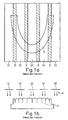
- FIGS. 1 and 2 schematically illustrate a scanning of a jaw K in a plan view and a front view, respectively.
- five gauges S 1, S2, S3, S4 and S5 are detected side by side.
- the five measuring strips S1 to S5 overlap in areas B, which are hatched in FIG. 1a and omitted in FIG. 1b for the sake of clarity;
- FIG. 1b serves only to clarify the position of the measuring strips S1 to S5 in the front view of the jaw K and the direction of the scanning radiation according to the arrows P.
- the overlapping areas B allow the data of the individual measuring strips to be combined by matching methods to form an overall image of the Kiefers K.
- FIG. 1c and 1d A variant of the above technology according to WO 02/39056 A1 is also shown in Figs. 1c and 1d in a plan view and a front view.
- measuring strips S6, S7, S8, S9, S10, S11, S12 and S13 are generated, which, however, only consist of so-called fields, so that indeed more measuring strips than in the variant according to FIGS and 1b are generated and treated, but these gauges get along with significantly lower data size.
- the position of the gauges S6 to S 13 is shown in the plan view of Fig. 1c with respect to the jaw K.
- the irradiation directions are schematically illustrated by arrows P1, P2, P3 and P4 for the measuring strips S6, S 11, S 13 and S 10 in FIG.
- FIG. 1d In FIG. 1c, overlapping areas B of the individual adjacent measuring strips are again shown hatched.
- the irradiation directions for the individual measuring strips changed with respect to the prior art give more accurate data of the jaw K, with a lower data and processing volume than in the prior art by using only half-fields.
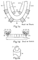
- a single measuring object in the form of a tooth Z is shown schematically in a perspective view in FIG. 2a, as installed on a measuring pot M, which for this purpose is filled, for example, with a plasticine into which the tooth Z with its lower end (not visible) is plugged.
- FIG. 2c the position of measurement strips or measurement lines S is shown schematically in FIG. 2c, and FIG. 2c shows the signal image for a measurement strip or measurement line Sx, in which only one measurement point Dx is obtained.
- the read-out direction (line direction) is also shown with the arrow A1.
- the sum of all measurement strips or measurement lines S forms the surface of a chip C as an image capture device, which may be, for example, a CCD chip or any other camera device.
- a plurality of measuring points for example Dy1 and Dy2 or Dza to Dzn, obtained, as Figs. 2d and 2e illustrate, which are analogous to FIGS. 2b and 2c.
- the read-out direction is in accordance with the arrow A2 in FIG. 2d, and the chip C and the position of the measuring strips or measuring lines S are consequently rotated by 90 ° with respect to the prior art.
- two measuring points Dy1 and Dy2 are obtained in the measuring line Sy.
- the measurement in the line Sz even leads to a multiplicity of measuring points Dza to Dzn.
- the chip arrangement is then preferably recalculated and simulated by software as in the prior art (see FIG. 2b).
- the read-out direction thus obtained again as in the prior art, however, again contains per line or line a plurality of measuring points which can be computationally detected as the first point, then the second point, etc.
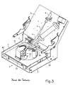
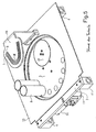
- FIGS. 5, 6 and 7 which is an enlarged view of a part of Fig. 3, a surface detection device 1 is shown with a laser optics 4, from which a laser line beam L emanates.
- the intersection of the laser line beam L with the rectangular image field F originating from the objective defines the measuring field F.
- Each object to be measured must be passed through this measuring field F.
- the "passing through” the measuring field F is accomplished by means of a linear guide 83 (or reference numeral 4 'in Figs. 5 and 6).
- a turntable 33 (or reference numeral 5 in FIGS. 5, 6 and 7) rotates from measuring pot 84 to measuring pot 84 (in FIG Numeral 8 denotes).
- FIG. 3 also in FIG. 5, for example, only two measuring pots 8
- FIG. 8 only two measuring pots 84 are shown in FIG. 3 (also in FIG. 5, for example, only two measuring pots 8), wherein, for example, seven pieces in total can be mounted.
- a measuring pot 84 equipped with a tooth arrives in the measuring field, the rotation of the large turntable 33 (or 5 in FIGS. 5, 6 and 7) stops.
- the turntable 33 thus serves only for positioning the pots 84 (or 8 in FIG. 5) equipped with individual teeth and / or a jaw, which will be discussed later.
- the measurement itself takes place, as explained above, by means of a linear movement of the measuring stage 53 on the linear bearings 83 or 4 '(FIG. 5).
- the pot 84 located in the measuring range can be rotated about its own axis between the individual measurements. This leads eg to eight views or the pot 84 (or 8 in FIG. 5) is rotated between the measurements by 45 ° about its own axis. Thus, in such a case, eight measuring strips arise from different views. Parts of the obtained surface information occur in several gauges. By means of these overlapping areas, suitable devices or methods in the form of, for example, an already explained above matching software to assemble the individual strips to a complete 3D surface image of a single tooth with high accuracy.
- the result can be seen in the image of FIG. 8.
- the direction of the measuring strips are to be recognized as five white lines (examples are the designations 11,12 and I3 and otherwise only the lines are drawn). Although this measurement result does not contain all the data of the jaw, on the outside there is enough data to be able to do this automatically with the data of the individual stumps.
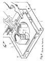
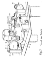
- a turntable 5 serves to locate various single tooth measuring cups 8 under the laser measuring arrangement (see FIG 3) to transport.
- This turntable 5 is driven by a friction wheel 15 (see FIG. 6).
- This friction wheel 15 is pressed by means of a spring plate 24 (see FIG. 6) on the front side of the turntable 5. As a result, any wear of a rubber surface or the rubber material of the friction wheel 15 is compensated.
- the position of the turntable 5 is detected by means of an encoder disc 28.
- the disc is designed as a sheet 28 (see FIG. 6), which has slots 100 exactly at the locations at which required stop positions lie.
- the slots 100 are detected by means of a light barrier 33 (see FIG. 6).
- a control software evaluates the light barrier signals and starts / stops the Table or plate 5.
- the turntable 5 contains seven positions / pots for single teeth. If a work contains more than seven preparations / teeth (a maximum of 14 per jaw is possible), the work can be scanned in 2 batches.
- a pulley or a toothed belt can be used.
- the frame of the device / the device on two guide rods 83 (see FIGS. 3 and 4) suspended.
- the complete frame of the device thus consists only of two side parts 2 (see FIGS. 3 and 4), the guide rods 83 (see FIGS. 3 and 4) and an optical plate (FIG. 5).
- Inaccuracies caused by the mechanical design of the linear rod guide are compensated by software (e.g., so-called "look-up tables").
- a precision spindle 94 (see Figures 3 and 4) is mounted on the side of the travel table on which the laser assembly is located. Angular errors of the spindle have less effect.
- the advantages of this embodiment are low production costs, high precision, significantly lower transport weight and smaller design.
- Another improvement over the prior art before the WO 02/39056 A1 can be made for electrical protection of the laser diode.
- the laser optics, the laser diode and the drive electronics for the laser diode are housed together in a metal housing. This results in a better protection for the diode, especially against electrostatic charges from the outside, as well as a quick replacement in case of repairs as advantages.
- a template 54 is required (see FIG. 5). Since there are jaw models with different diameters (eg for children and adults), the jaw model must be adapted according to the size. For this purpose, for example, 3 different adjustment contours I, II and III are engraved on the transparent plexiglass pane, from which the template 54 is preferably formed, or otherwise suitably applied.
- the turntable 5 (FIGS. 5, 6 and 7) transports the individual pots 8 to the measuring position in front of the friction wheel 15. As the turntable 5 moves, the frictional contact of the poppet 8 with the friction wheel 15 is automatically produced.
- the innovation is that the friction wheel 15 is made of rubber or at least has a rubber-running surface, the mating wheel 7, however, made of solid metal. This has the advantages of a lower price, a simple production and a long service life.
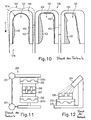
- FIG. 10 Shown are 3 tooth stumps 101, each consisting of a ground part 101a and a residual tooth area 101b.
- the grinding is done manually by a dentist and forcibly leads to undercuts 102, which differ in the shape, location and size when viewing several adjacent individual teeth or their stumps 101.
- a so-called coping 104 is first prepared for at least one stump 101, which usually in exactly one Insertion or Aufsteckides according to the arrow E can be pushed over the stump 101. It is not possible that the cap 104 fills the undercuts 102, as a postponement would otherwise no longer be possible.
- 3 stumps 101 are juxtaposed and are combined according to 3 copings 104 to form a bridge, in each case adjacent copings 104 being connected by means of a respective web 105.
- the WO 02/39056 A1 be used to further improve the approach for the preparation of dental prostheses.
- recommendations can be made for the treating dentist, by which reworking of the tooth stumps an improvement of the seat and stability of the prosthesis to be produced, including a significant reduction of the undercuts or "dead spaces" 102 can be achieved.
- the method according to the WO 02/39056 A1 extended to the effect that with respect to a detected 3D data set of a tooth stump 101 or a combination of multiple tooth stumps 101, an optimal attachment direction for copings 104, in particular a connection of a plurality of copings 104 to a bridge 106, is calculated on the proviso that changes in shape on the stump of the tooth / the tooth stumps 101 are possible.
- the method and system according to WO 02/39056 A1 thus serves not only to determine an adaptation to given circumstances for the production and the attachment of copings 104 or bridges 106, but also to change the given circumstances in order to optimize the result, ie the prosthesis.
- the method and system may include providing a graphical display of the stumps, including, for example, specially colored areas for rework, which serves as the basis for a dialogue between a dental laboratory and a dentist.
- Characteristic of an inlay preparation is the sharp-edged edge of the preparation, as illustrated by the comparison of FIGS. 13 and 14.
- the light signal to be evaluated on the camera chip contains information essential to the method described: While the laser line touches a surface portion that does not include an edge, as illustrated in FIG. 13, the full width of the laser beam is reflected.
- a tooth Z with a tooth surface ZO on which a laser beam LS from a laser light source LQ with a beam width LB impinges.
- the reflected beam RS has a width LBRI, with which it meets a CCD chip CCD as a detection device.
- the laser beam LS strikes an edge, as shown in FIG.
- the shape of the signal to be evaluated likewise changes, as does the representation of the corresponding signals in each case in the lower half of Figures 13 and 14. If a symmetrical Gaussian curve is described for the area (compare Figure 13), the signal runs in 14), as can be seen in FIG.
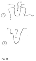
- FIG. 15 which schematically shows the signal form of a signal 1 resulting from the scanning of a surface (analogous to FIG. 13) of a signal 2 which is obtained on reaching an edge of a hole in a surface, and a signal 3 is sketched, which is obtained directly at an edge of a hole or here specifically a tooth cavity ZK in a surface (analogous to FIG. 14).
- the information of width variation and shape of the signal can be processed to optimally determine the actual edge of the edge K. By repeatedly measuring this edge K from several solid angles using the described method, this information can be checked against each other by means of matching methods and determined by averaging in the edge region to its final shape.
- a 3D data set for example a tooth inlay cavity, which has been scanned in this way and which 3D data set has been further processed, for example, by suitable surface triangulation methods, typically contains surfaces which are described by at least three or more corner points. These surfaces are connected by common edges or dots, as the graph of FIG. 16 illustrates.
- the method described for partially or fully automatic edge detection and separation is now carried out by the a priori information that edges of preparations have above-average, high curvatures or angles.
- a valence of the curvature can subsequently be determined by a difference analysis of the point normal from the normals of the area data sets.
- the following step attempts to increase and classify the significance of various criteria by finding neighborhood relationships.
- one criterion may be the neighborhood relationships with respect to a contiguous line. This is the basic building block for automatic edge detection.
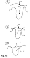
- edges are now optimally analyzed, recognized and merged into a contiguous edge course, as shown schematically in the method step diagrams of FIGS. 17 and 18.
- the dental inlay only the surface segments located within an edge profile are used.
- FIG. 17 a complete dataset of a stump preparation SP with a tooth cavity ZK prepared for an inlay and its edges or edges K is schematically shown below (1.) only in a side view, but in reality it is altogether one 3D dataset acts, so a three-dimensional data representation of the stump preparation.
- step (2) the step of recognizing and separating the edges or edges K is illustrated only schematically in FIG. 17, wherein again the two-dimensional representation for the 3D data set from step (1) of FIG. 17 is representative.
- the edge detection takes place, for example, as explained with reference to FIGS. 13 to 16 and shown in these figures.
- step (3) is further illustrated schematically for simplicity as a two-dimensional representation of the complete 3D dataset, wherein, for example, by importing a database occlusal surface KF, the missing side of the prepared and later inlay becomes the prepared tooth cavity data ZK which otherwise determines the shapes and dimensions of the inlay.
- the sales area data stored in a database eg for the lower molar mandible
- the original tooth shape data measured before the treatment is imported by the dentist, or the measured shape data individually from a dental technician for the inlay imported into wax modeled occlusal surface.
- step (4) of FIG. 18 the data of the imported purchase area KF are linked to the data of the prepared tooth cavity ZK, which in turn is represented on the two-dimensional schematic example as representative of the respective 3D data sets of purchase area KF and tooth cavity ZK.
- the purchase-area data are optimally adapted to the edge and placed on the edge.
- step (5) of FIG. 18 a morphing of the occlusal surface and a separation of the supernatant, so that a finished inlay data set IS is obtained, which, for the sake of simplicity, continues to be only a two-dimensional representation of the actual data set with the complete 3D data is shown.
- the occlusal surface for example, can be adapted to the opposing bite by means of morphing.
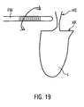
- the resulting 3D data set can be used for the CNC production of inlay parts. It is particularly advantageous for the precision of the inlay I, if the holding web HS of the inlay I remaining after the milling process has been completed with a milling tool FW is positioned in the area of the chewing surface KF, as illustrated with reference to FIG. 19.
- Pre-assembled parts are often used in conventional dental technology.
- implant posts, abutments and attachments are mechanically connected to the conventional dentures.
- the invention makes it possible to avoid the process of assembling several prefabricated parts, for example with adhesive. In addition to cost reasons, this also results in an improved health tolerance for the patient, since only one material is inserted into the body. Furthermore, a longer life and higher overall precision is possible.
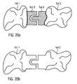
- a preferred component of the presently treated aspect of the invention is that 3D CAD design data from a prefabricated dental prosthesis or from design elements or fasteners of dental prostheses and 3D measurement data from tooth stumps and / or tooth forms (superfaces) are brought together.
- Fig. 20a exemplifies a conventional end product situation
- Fig. 20b shows a final product situation according to the present invention.
- the method can be applied taking into account the dental situation of the patient.
- measurement data of the alveolar ridge In addition to measurement data of the alveolar ridge, measurement data of neighboring teeth can also be displayed.
- a particular advantage of this method is that the insertion direction can be taken into account in the construction of bedding parts.
- the mix of design data, CAD design tools, 3D matching tools and measurement data processing leads to a multitude of technical possibilities and process flows.
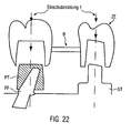
- FIGs. 21a and 21b and 22 Another example of the invention is illustrated in Figs. 21a and 21b and 22:
- FIGS. 21a and 21b show an implant abutment PF (with abutment) and a stump ST, which are to be crowned together by means of a bridge.
- another stump can also form the basis for the further procedure, or several parts can be present as two which can be any desired, for example, implant abutments or tooth stumps.
- the situation is for example by means of technology according to the prior art, in particular the WO 02/39056 A1 to obtain 3D data sets of the implant piercer PF in its position and the tooth stump in position and shape. If necessary, it is also possible to detect the shape of the implantate pillar, provided that it is not an assembly part whose 3D data is already present in the system, so that only its position needs to be determined.
- Insertion direction 1 through the stump ST and insertion direction 2 through the implant pier PF.
- the insertion direction 1 is selected for this purpose, which can be realized for example fully automatically by means of the software used, but also semi-automatically selected by selectivity and adjustability within the software limits by an operator and for the additional procedures can be specified.
- a purely manual choice of insertion direction which allows a strong involvement of expert know-how, especially for complicated arrangements.
- a software can calculate a primary part PT according to FIG. 21b which acts to unify the two insertion directions as an adapter on the implant pier PF, so that the insertion direction 2 also applies to the latter.
- margins for the primary part PT or the adapter either fully automatically by the software or semi-automatically, by predetermined margins are set and adjustable within limits, or manually adjusted by the user freely specifying the edges.
- the software can also be defined as a milling direction, specifically as a function of the direction of insertion, but overall, taking into account various parameters, for the tooth replacement part.
- the internal data set is initially used to measure the stump ST, including its surroundings U, in which the implant abutment PF lies.
- the design data set of the implant post PF (with abutment) is loaded and spatially assigned to the measured data by means of a matching process.
- This is to use the data of the design dataset for the CNC manufacturing of the part, as this can achieve a higher precision of the final product than in the processing of measurement data.
- the outer contour of the primary part can also be artificially generated or CAD-constructed, with one or the insertion direction 1 defined by the stump ST being used. Thus, an individual, mechanically precise primary part can be manufactured.
- Essential for the present invention is the use of a primary part as an adapter for a tooth replacement part, which relates to a plurality of tooth stumps, implant posts, etc., to provide a common insertion direction can.
- a primary part as an adapter for a tooth replacement part, which relates to a plurality of tooth stumps, implant posts, etc., to provide a common insertion direction can.
Landscapes
- Health & Medical Sciences (AREA)
- Oral & Maxillofacial Surgery (AREA)
- Dentistry (AREA)
- Epidemiology (AREA)
- Life Sciences & Earth Sciences (AREA)
- Animal Behavior & Ethology (AREA)
- General Health & Medical Sciences (AREA)
- Public Health (AREA)
- Veterinary Medicine (AREA)
- Physics & Mathematics (AREA)
- Optics & Photonics (AREA)
- Dental Tools And Instruments Or Auxiliary Dental Instruments (AREA)
- Dental Prosthetics (AREA)
- Length Measuring Devices By Optical Means (AREA)
- A Measuring Device Byusing Mechanical Method (AREA)
Abstract
Description
Die vorliegende Erfindung betrifft Einrichtungen und Verfahren zur Herstellung von Zahnersatzteilen, insbesondere unter Verwendung von Oberflächenerfassungs- und -erzeugungseinrichtungen sowie Verfahren zur Oberflächenerfassung und -erzeugung zur Erfassung und/oder Erzeugung von Oberflächen von Zähnen.The present invention relates to devices and methods for the production of dental prostheses, in particular using surface detection and production devices and methods for surface detection and production for detecting and / or generating surfaces of teeth.
Grundlegenden Technologien, die zusammen mit der vorliegenden Erfindung nutzbar sind oder mit denen sie kombinierbar ist, sind in den Offenlegungsschriften
Die
In der ursprünglichen Version der
Gemäß der
Weitere alternative oder zusätzliche Ausgestaltungen einer Oberflächenerfassungseinrichtung gemäß der
Eine weitere Variante einer Oberflächenerfassungseinrichtung insbesondere zur Gewinnung von Oberflächendaten von Zähnen nach der
Spezielle vorzugsweise insbesondere mechanische Ausgestaltungen der Oberflächenerfassungseinrichtung richten sich nach dem Offenbarungsgehalt der Figuren 3 und 4 und/oder 5, 6 und 7 sowie der diesbezüglichen Beschreibung.Special, preferably mechanical, embodiments of the surface detection device are based on the disclosure content of FIGS. 3 and 4 and / or 5, 6 and 7 as well as the description relating thereto.
Bevorzugt ist es ferner, wenn bei der Oberflächenerfassungs- und Erzeugungseinrichtung insbesondere zur Herstellung von Zahnersatz die Einrichtungen zur Ablaufs- und/oder Aufwandsoptimierung Einrichtungen zur optimierten Vorbereitung wenigstens eines Zahnstumpfes zur Herstellung und zum Aufsetzen einer Zahnprothese darauf und/oder Einrichtungen zur Berücksichtigung der Bißstellung von Ober- und Unterkiefer enthalten.It is furthermore preferred if, in the case of the surface detection and generating device, in particular for the production of dental prostheses, the devices for drainage and / or expense optimization devices for optimized preparation of at least one tooth stump for the manufacture and placement of a dental prosthesis thereon and / or devices for taking into account the bite position of Upper and lower jaw included.
Die Oberflächenerfassungs- und/oder Erzeugungsverfahren gemäß der
Schließlich wird durch die
Einzelne Aspekte der
Gemäß einem Aspekt der
Gemäß einem weiteren Aspekt der
Zum einen wird dies gemäß der
Die Scannertechnologie wird im Rahmen der
Insbesondere die vorstehende Verbesserung, aber allgemein die verwendete Abtasttechnologie kann dadurch vorteilhaft weitergebildet werden, dass ähnlich einem Stroboskopeffekt der verwendete Laser gepulst angesteuert und beispielsweise der Tisch, der das Objekt trägt, dessen Oberfläche erfaßt werden soll, wie z.B. einen Zahn oder ein Modell davon, insbesondere kontinuierlich verfahren wird. Durch den gepulsten Laserstrahl werden von jeder Relativposition von Objekt und Kamera Momentaufnahmen oder "Standaufnahmen" erstellt, da das Objekt während der kurzen Belichtungszeit mit einem Laserstrahlpuls scheinbar steht und in dieser Position von der Kamera aufgenommen werden kann. Besonders bevorzugt ist jeder einzelne Laserimpuls mit der Aufnahme eines Halbbildes gekoppelt.In particular, the above improvement, but in general the scanning technology used can be advantageously developed, that similar to a stroboscopic effect of the used Pulsed pulsed laser and, for example, the table that carries the object whose surface is to be detected, such as a tooth or a model thereof, in particular, is moved continuously. The pulsed laser beam creates snapshots or "still images" of each relative position of the object and the camera, since the object appears to be exposed to a laser beam pulse during the short exposure time and can be captured by the camera in this position. Particularly preferably, each individual laser pulse is coupled with the recording of a field.
Noch eine weitere Verbesserung der Scannertechnologie gemäß der
Des weiteren wird die Scannertechnologie gemäß dem noch älteren Stand der Technik durch die
Die bekannte Scannertechnologie läßt sich außerdem noch dadurch verbessern, dass entsprechend der
Gemäß einem weiteren Aspekt der
So schafft die
Eine elektronische Archivierung von Kiefer-/Gebißdaten kann aber noch in vielerlei anderen Hinsichten vorteilhaft genutzt werden. So ermöglichen diese Daten mittels einer geeigneten EDV eine Nachempfindung der Bißstellung von Ober- und Unterkiefern. Insbesondere kann dies erzeugt werden, indem zunächst der Unterkiefer vermessen wird, dann ein Bißregistrat (Abdruck im Patientenmund, während er zubeißt) auf den Unterkiefer gelegt wird und nochmals vermessen wird. Damit sind beide Zahnoberflächen in der Bißsituation ermittelt. Beide Datensätze können getrennt oder zusammen visualisiert werden und alle damit verbundenen zahnärztlichen Analysen z.B. qualitativ oder quantitativ (in Form von Abstands- oder Volumenmessungen) durchgeführt werden. Zur Ergänzung kann auch der komplette Oberkiefer vermessen und mittels des Bissregistrats und beispielsweise einer Matching-Software räumlich referenziert werden. Ebenso können Kaubewegungen mittels Aufnahme der Kieferbewegung und Bißregistrat am Computer simuliert werden. Die Referenzierung der Messdaten von Ober- und Unterkiefer kann auch zur Modulation von Zahnersatz im Zusammenhang mit der CAD-CAM-Technologie verwendet werden.However, electronic archiving of jaw / dentition data can be used to advantage in many other ways. Thus, these data make it possible to simulate the biting position of the upper and lower jaw by means of a suitable EDP. In particular, this can be produced by first measuring the lower jaw, then placing a bite registration (impression in the patient's mouth while biting it) on the lower jaw and measuring it again. Thus, both tooth surfaces are determined in the biting situation. Both datasets can be visualized separately or together and all associated dental analyzes e.g. qualitative or quantitative (in the form of distance or volume measurements). In addition, the entire upper jaw can be measured and spatially referenced by means of the bite registration and, for example, a matching software. Likewise, chewing movements can be simulated by recording the jaw movement and bite registration on the computer. The referencing of the measurement data of upper and lower jaw can also be used for the modulation of dentures in connection with the CAD-CAM technology.
Eine weitere Variante der
Ein weiterer Gesichtspunkt der
Im Rahmen der
Ferner ist Gegenstand der
Eine entsprechende Oberflächenerfassungsein- oder -vorrichtung besteht beispielsweise aus einem Lineartisch, einer CCD-Kamera, einer Framegrabberkarte und einem Laserlinienmodul. Zur Datenerfassung wird die Laserlinie permanent auf das Messobjekt projiziert. Der Messtisch bewegt das Objekt schrittweise unter der Messanordnung (Laserlinie und CCD-Chip) hindurch. Nach jedem Schritt erfolgt eine Messung.A corresponding Oberflächenerfassungsein- or device consists for example of a linear table, a CCD camera, a Framegrabberkarte and a laser line module. For data acquisition, the laser line is permanently projected onto the measurement object. The measuring stage moves the object step by step under the measuring arrangement (laser line and CCD chip). After each step, a measurement takes place.
Dabei ist der frühere genaue Ablauf folgendermaßen: Der Messtisch fährt in eine Startposition und stoppt. Das Objekt muß ruhen, damit kein "Verwackeln" der Aufnahme zu Messungenauigkeiten führt. Dann ließt die CCD-Kamera eine Zeile aus (Vollbild) und übergibt das Signal an die Framegrabberkarte. Anschließend wird der Tisch beschleunigt (Anfahrrampe). Danach wird der Tisch wieder abgebremst und in einer vorgegebenen Position gestoppt (Bremsrampe). Die CCD-Kamera ließt dann die nächste Zeile aus. Dieser Gesamtvorgang läuft unter Verdunkelung ab. Die Laserdiode kann nur auf eine gewisse Leistung hochgeregelt werden, damit das Signal nicht übersteuert.The earlier exact procedure is as follows: The measuring table moves to a starting position and stops. The object must rest, so that no "blurring" of the recording leads to measurement inaccuracies. Then the CCD camera reads one line (full screen) and passes the signal to the frame grabber card. Then the table is accelerated (approach ramp). Then the table is braked again and stopped in a predetermined position (braking ramp). The CCD camera then reads out the next line. This whole process takes place under darkening. The laser diode can only be up-regulated to a certain power so that the signal is not overdriven.
Gemäß der
Mit der Ausgestaltung aus der
Neben den bereits oben und vorstehend beschriebenen technischen Spezifikationen zum Thema "Stroboskoplaser" etc. liegen im Rahmen der
Insbesondere gegenüber dem technischen Stand der Vorrichtung zur Herstellung eines Zahnersatzes gemäß der
Beispielsweise basierend auf und/oder in Kombination mit den vorstehenden Darlegungen aus der
Zur Erreichung dieses Ziels werden insbesondere geschaffen:
- Einrichtungen und Verfahren zur teil- oder vollautomatischen Randerkennung von Inlaypräparationen, sowie
- Einrichtungen und Verfahren zur Herstellung von komplexen Zahnersatzkonstrudtionen.
- Devices and methods for partially or fully automatic edge recognition of inlay preparations, as well as
- Facilities and methods for making complex dental prosthesis reconstructions.
Die Vorteile dieser erfindungsgemäßen Einrichtungen und Verfahren liegen insbesondere bei Ablaufs- und/oder Aufwandsoptimierung.The advantages of these devices and methods according to the invention are in particular in the case of process and / or expense optimization.
Insbesondere und in erster Linie, jedoch nicht beschränkend, werden mit den einzelnen Aspekten der vorliegenden Erfindung technische Verbesserungen gegenüber der technischen Lehre in der
Einrichtungen und Verfahren zur Herstellung von Zahnersatzteilen gemäß der Erfindung sind in den unabhängigen Ansprüchen 1 und 8 angegeben. Weitere bevorzugte und vorteilhafte Ausgestaltungen der Erfindung ergeben sich aus den einzelnen abhängigen Ansprüchen und deren Kombinationen.Devices and methods for the production of dental prostheses according to the invention are given in the
Die vorliegende Erfindung schafft Oberflächenerfassungs- und Erzeugungseinrichtungen,
mit Einrichtungen zur Erfassung von 3D-Daten wenigstens eines Zahnersatzbasisobjektes, wie eines Zahnstumpfes oder Implantatpfostens, und einer Umgebung davon, sowie mit Einrichtungen zur dateamäßigen Erzeugung und Herstellung eines Zahnersatzteils unter Einbeziehung der 3D-Daten des Zahnersatzbasisobjektes,
wobei ferner vorgesehen sind:
- Einrichtungen zur Ermittlung und/oder Festlegung einer Einschubrichtung des Zahnersatzteils, das auf das Zahnersatzbasisobjekt aufzuschieben ist, sowie
- Einrichtungen zur Ermittlung und Herstellung eines Primärteils, das vor dem Zahnersatzteil auf das Zahnersatzbasisobjekt aufzuschieben ist und das für das Zahnersatzteil eine gewünschte Einschubrichtung die von der Einschubrichtung verschieden ist, die für das Aufschieben des Primärteils auf das Zahnersatzbasisobjekt gegeben ist, und
- dass die Einrichtungen zur datenmäßigen Erzeugung und Herstellung eines Zahnersatzteils ausgelegt sind, letzteres unter Einbeziehung der 3D-Daten des Primärteilsdatenmäßig zu erzeugen und herzustellen.
with means for acquiring 3D data of at least one denture base object, such as a tooth stump or implant post, and an environment thereof, as well as means for datamäßigen generation and production of a dental prosthesis part including the 3D data of the dental prosthesis base object,
further provided:
- Means for determining and / or determining an insertion direction of the dental prosthesis, which is postponed to the dental prosthesis base object, as well as
- Means for determining and producing a primary part, which is to be postponed before the dental prosthesis part on the dental prosthesis base object and that for the dental prosthesis part a desired Insertion direction which is different from the insertion direction, which is given for the postponement of the primary part on the dental prosthesis base object, and
- in that the devices for the data generation and production of a dental prosthesis part are designed to generate and produce the latter with the involvement of the 3D data of the primary part.
Bevorzugte Weiterbildungen davon sind derart, dass ferner Kombinaiionseinnchtungen vorgesehen sind, die zum Zusammenführen von 3D-Daten von wenigstens 2 Zahnersatzbasisobjekten in Form, Lage und Stellung zueinander ausgelegt sind, und dass die Einrichtungen zur Herstellung eines Zahnersatzteils ausgelegt sind, ein gemeinsames Zahnersatzteil für alle beteiligten Zahnersatzbasisobjekte herzustellen.Preferred developments thereof are such that further combination devices are provided, which are designed for merging 3D data of at least two dental prosthesis base objects in shape, position and position relative to one another, and in that the devices for producing a dental prosthesis part are designed, a common tooth replacement part for all involved To make dentures base objects.
Weiterhin ist es bevorzugt, wenn zur Erfassung von Form, Lage und/oder Stellung jedes Zahnersatzbasisobjektes und/oder jedes Primärteils berührungslos arbeitende Erfassungseinrichtungen enthalten sind.Furthermore, it is preferred if non-contact detection devices are included for detecting the shape, position and / or position of each dental prosthesis base object and / or each primary part.
Bei nach einer weiteren vorteilhaften Ausgestaltung der vorliegenden Erfindung ist vorgesehen, dass für die Ermittlung und/oder Festlegung und/oder Erzeugung und/oder Zusammenführung von Messdaten, 3D-Daten und -Datensätzen, Archiv- und/oder Vorgabedaten und/oder -datensätzen sowie Einschubrichtungen elektronische Verarbeitungseinnchtungen vorgesehen sind, denen Prozessoreinrichtungen, Speichereinrichtungen, Schnittstellen und Steuereinrichtungen zugeordnet sind oder in denen Prozessoreimichtungen, Speichereinrichtungen, Schnittstellen und Steuereinrichtungen enthalten sind. Alternativ oder zusätzlich kann mit Vorzug vorgesehen sein, dass Einrichtungen gemäß der
Im Umfang der vorliegenden Erfindung kann ferner vorgesehen sein, dass Datenfernübertragungseimichtungen enthalten sind, so dass die Erfassungseinrichtungen und jedenfalls die Erzeugungseinrichtungen und/oder die Herstellungseinrichtungen lokal getrennt voneinander aufstellbar sind, wobei vorzugsweise eine Mehrzahl von lokal getrennt voneinander aufgestellte Erfassungseinrichtungen mit einer zentralen Erzeugungseinrichtung gekoppelt ist.Within the scope of the present invention, it may further be provided that remote data transmission devices are included, so that the detection devices and in any case the generation devices and / or the production devices can be set up locally separately from one another, wherein preferably a plurality of locally separate detection devices are coupled to a central generation device ,
Durch die Erfindung werden ferner geschaffen Obesflächenerfassungs- und Erzeugungsverfahren, wobei von einem Zahnersatzbasisobjekt, wie einem Zahnstumpf oder implantatpfosten, und einer Umgebung davon 3D-Daten erfasst werden und dann auf der Basis dieser 3D-Daten des Zahnersatzbasisobjektes ein darauf aufzuschiebendes Zahnersatzteil hergestellt wird, wobei vor der Herstellung des Zahnersatzteils eine Einschubrichtung des Zahnersatzteils auf das Zahnersatzbasisobjekt ermittelt und/oder festgelegt wird, auf der Basis dieser 3D-Daten des Zahnersatzbasisobjektes ein Primärteil ermittelt und hergestellt wird, mit dem für das Zahnersatzteil eine gewünschte Einschubrichtung geschaffen wird, die von der Einschubrichtung verschieden ist, die für das Aufschieben des Primärteils auf das Zahnersatzbasisobjekt gegeben ist, und das Zahnersatzteil passend zum Aufschieben auf das Primärteil auf der Basis der 3D-Daten des Primärteilsdatenmäßig erzeugt und hergestellt wird.The present invention further provides for obverse surface detection and production methods wherein 3D data is acquired from a base denture object such as a tooth stump or implant post and an environment thereof, and then a dental prosthetic item to be inserted thereon is prepared based on said 3D data of the dental prosthesis base object before the production of the dental prosthesis, a direction of insertion of the dental prosthesis part is determined and / or determined on the dental prosthesis base object, based on this 3D data of the dental prosthesis base object, a primary part is determined and produced, with the tooth replacement part a desired insertion direction is created, which is different from the insertion direction, for the postponement of the primary part is given to the dental prosthesis base object, and the dental prosthesis part is generated and manufactured to be fit on the primary part on the basis of the 3D data of the primary part.
Bevorzugst kann dabei ferner vorgesehen sein, dass 3D-Daten von wenigstens 2 Zahnersatzbasisobjekten in Form, Lage und Stellung zueinander erfaßt werden, und dass ein gemeinsames Zahnersatzteil für alle beteiligten Zahnersatzbasisobjekte datenmäßig erzeugt und hergestellt wird, wobei vorzugsweise 3D-Daten von wenigstens 2 Zahnersatzbasisobjekten in Form, Lage und Stellung zueinander einzeln erfaßt und dann zusammengeführt werden.Preferably, it may further be provided that 3D data of at least two basic dental prosthesis objects in shape, position and position to each other are detected, and that a common dental prosthesis for all dentures base objects is generated and produced in terms of data, preferably 3D data of at least 2 prosthetic base objects in Form, position and position individually detected and then merged.
Weiterhin kann bei dem Oberflächenerfassungs- und/oder Erzeugungsverfahren nach der Erfindung vorgesehen sein, dass die Erfassung von Form, Lage und/oder Stellung jedes Zahnersatzbasisobjektes und/oder jedes Primärteils berührungslos erfolgt, und/oder dass Einrichtungen gemäß der
Bei weiteren vorzugsweisen Ausgestaltungen kann vorgesehen sein, dass Messdaten, 3D-Daten und -Datensätze, Archiv- und/oder Vorgabedaten und/oder -datensätze sowie Einschubrichtungen insbesondere aus Messeinrichtungen und/oder Speichereinrichtungen verwendet werden, wobei vorzugsweise Daten von vorkonfektionierten Teilen aus Datenbanken verwendet werden.In further preferred embodiments, it can be provided that measurement data, 3D data and data sets, archive and / or default data and / or data sets and insertion directions are used in particular from measuring devices and / or memory devices, preferably using data from prefabricated parts from databases become.
Ferner liegt es im bevorzugten Rahmen der vorliegenden Erfindung, wenn CAD/CAM-Verfahren enthalten sind, und/oder wenn die Erfassung von Objekten und insbesondere deren 3D-Daten und Datensätzen unter Zwischenschaltung von Datenfernübertragung örtlich getrennt von der Herstellung von Primärteilen und/oder Zahnersatzteilen erfolgt, wobei vorzugsweise eine Erfassung an einer Mehrzahl von Orten durch Datenfernübertragung zu zentraler Erfassung und/oder Herstellung gekoppelt ist.Furthermore, it is within the preferred scope of the present invention, when CAD / CAM methods are included, and / or when the detection of objects and in particular their 3D data and data records with the interposition of remote data transmission locally separate from the production of primary parts and / or dental prostheses is carried out, wherein preferably a detection at a plurality of locations is coupled by remote data transmission to central detection and / or production.
In Kombination mit den vorstehenden Ausgestaltungen von OberSachenerfassungs- und/oder Erzeugungseinnchtungen, oder auch für sich alleine, schafft die Erfindung ferner solche Oberflächenerfassungs- und/oder Erzeugungseinrichtungen, bei denen Einrichtungen zur teil- oder vollautomatischen Randerkennung von Inlaypräparationen vorgesehen sind, und/oder bei denen Einrichtungen zur Herstellung von komplexen Zahnersatzkonshuktionen vorgesehen sind.In combination with the above embodiments of OberSachenerfassungs- and / or Erzeugsenseinnchtungen, or on its own, the invention also provides such surface detection and / or generating devices in which means for partially or fully automatic edge detection of inlay preparations are provided, and / or at which facilities are provided for the production of complex Zahnersatzkonshuktionen.
Analog enthalten die vorstehenden Obeerflächenerfassungs- und/oder Erzeugungsverfahren gemäß der vorliegenden Erfindung jeweils einzeln oder in Kombination mit den vorstehend angegebenen Varianten solche Oberflächenerfassungs- und/oder Erzeugungsverfahren mit Verfahrensschritten zur teil- oder vollautomatischen Randerkennung von Inlaypräparationen, und/oder mit Verfahrensschritten zur Herstellung von komplexen Zahnersatzkonstruktionen.Analogously, the above Obeerflächenerfassungs- and / or production methods according to the present invention each individually or in combination with the above variants such surface detection and / or production method with process steps for partially or fully automatic edge recognition of inlay preparations, and / or with process steps for the production of complex dentures designs.
Darüber hinaus enthält die Erfindung weitere Varianten und Aspekte, die in der vorliegenden Beschreibung und den angefügten Zeichnungen anhand spezieller Ausgestaltungen oder in Form allgemeiner Angaben offenbart sind.In addition, the invention includes further variants and aspects disclosed in the present description and the attached drawings by means of specific embodiments or in the form of general information.
Nachfolgend wird die Erfindung lediglich exemplarisch anhand von Ausführungsbeispielen unter Bezugnahme auf die Zeichnung näher erläutert, in der:
- Fig. 1a
- eine schematische Draufsicht auf einen Kiefer mit eingezeichneten Abtaststreifen nach dem Stand der Technik ist,
- Fig. 1b
- eine schematische Frontansicht eines Kiefers mit eingezeichneten Abtaststreifen gemäß Fig. 1a ist,
- Fig. 1c
- eine schematische Draufsicht auf einen Kiefer mit eingezeichneten Abtaststreifen nach der
WO 02/39056 A1 - Fig. 1d
- eine schematische Frontansicht eines Kiefers mit eingezeichneten Abtaststreifen gemäß Fig. 1c ist,
- Fig. 2a
- eine perspektivische schematische Ansicht eines Messobjektes in Form eines Zahnes ist,
- Fig. 2b
- eine schematische Ansicht des Messobjektes aus der Fig. 2a mit eingezeichneten Abtaststreifen nach dem Stand der Technik ist,
- Fig. 2c
- eine schematische Ansicht eines Signalbildes einer Abtastzeile aus der Fig. 2b ist,
- Fig. 2d
- eine schematische Ansicht des Messobjektes aus der Fig. 2a mit eingezeichneten Abtaststreifen nach der
WO 02/39056 A1 - Fig. 2e
- eine schematische Ansicht eines Signalbildes einer Abtastzeile aus der Fig. 2d ist,
- Fig. 3
- eine schematische perspektivische Ansicht eines Ausführungsbeispiels einer Oberflächenerfassungseinrichtung nach der
WO 02/39056 A1 - Fig. 4
- eine vergrößerte Darstellung eines Teils aus der Fig. 3 ist,
- Fig. 5
- eine schematische perspektivische Ansicht des Ausführungsbeispiels der Oberflächenerfassungseinrichtung aus der Fig. 3 schräg von oben in einer anderen Einstellung und vergrößert ist,
- Fig. 6
- eine schematische perspektivische Ansicht des Ausführungsbeispiels der Oberflächenerfassungseinrichtung aus der Fig. 3 schräg von unten und vergrößert ist,
- Fig. 7
- eine schematische perspektivische Ansicht des Ausführungsbeispiels der Oberflächenerfassungseinrichtung aus der Fig. 3 schräg von unten und vergrößert sowie gegenüber der Ansicht aus der Fig. 6 etwas gedreht ist,
- Fig. 8
- eine graphische Darstellung eines Kiefers mit schematisch eingezeichneten Lagen von Messstreifen auf der Basis von gemäß der
WO 02/39056 A1 - Fig. 9
- eine graphische Darstellung des Kiefers aus der Fig. 8 mit gemäß der
WO 02/39056 A1 - Fig. 10
- eine schematische Teilansicht eines Kiefers zur Erläuterung eines weiteren Aspektes der
WO 02/39056 A1 - Fig. 11
- eine schematische Seitenansicht eines Kau- oder Bißsimulators zur Verdeutlichung eines weiteren Aspektes der
WO 02/39056 A1 - Fig. 12
- eins schematische Seitenansicht eines Kiefers aus der Fig. 11 in einer Oberflächenerfassungseimichtung ist,
- Fig. 13
- eine schematische Ansicht eines Ausführungsbeispiels einer Oberflächenerfassungseinrichtung gemäß der
WO 02/39056 A1 - Fig. 14
- eine schematische Ansicht eines Ausführungsbeispiels einer Oberflächenerfassungseinrichtung gemäß der
WO 02/39056 A1 - Fig. 15
- Schemadarstellungen von beispielhaften Signalformen eines Signals 1, das von der Abtastung einer Fläche herrührt, eines Signals 2, das bei Erreichen eines Randes eines Loches.in einer Fläche erhalten wird, und eines Signals 3 zeigt, das direkt an einem Rand eines Loches in einer Fläche erhalten wird,
- Fig. 16
- ein Beispiel einer graphischen Darstellung von Messergebnissen einer Erfassung einer Zahnoberfläche,
- Fig. 17
- schematische Darstellungen von zwei Verfahrenschritten bei der Herstellung eines Inlays gemäß einem Ausführungsbeispiel,
- Fig. 18
- schematische Darstellungen von drei weiteren Verfahrenschritten bei der Herstellung eines Inlays gemäß dem Ausführungsbeispiel aus der Fig. 17,
- Fig. 19
- eine schematische Darstellung eines noch weiteren Verfahrensschrittes bei der Herstellung eines Inlays gemäß dem Ausführungsbeispiel aus der Fig. 17,
- Fig. 20a/b
- schematische Darstellungen einer Vereinfachung bei der Herstellung von Zahnersatz gemäß einem weiteren Aspekt der vorliegenden Erfindung,
- Fig. 21a/b
- schematische Darstellungen einer Vereinfachung bei der Herstellung von Zahnersatz gemäß noch einem weiteren Aspekt der vorliegenden Erfindung, und
- Fig. 22
- eine schematische Darstellung des Ergebnisses der Vorgehensweise gemäß den Fig. 21 a/b.
- Fig. 1a
- is a schematic plan view of a jaw with marked scanning strip according to the prior art,
- Fig. 1b
- is a schematic front view of a jaw with marked scanning strip according to Fig. 1a,
- Fig. 1c
- a schematic plan view of a pine with marked scanning after the
WO 02/39056 A1 - Fig. 1d
- FIG. 1 is a schematic front view of a jaw with the scanning strip shown in FIG. 1c; FIG.
- Fig. 2a
- is a perspective schematic view of a measuring object in the form of a tooth,
- Fig. 2b
- FIG. 2 a is a schematic view of the measuring object from FIG. 2 a with the prior art scanning strips drawn in, FIG.
- Fig. 2c
- Fig. 2b is a schematic view of a signal image of a scan line of Fig. 2b;
- Fig. 2d
- a schematic view of the measuring object of FIG. 2a with marked scanning after the
WO 02/39056 A1 - Fig. 2e
- Fig. 2d is a schematic view of a signal image of a scanning line from Fig. 2d,
- Fig. 3
- a schematic perspective view of an embodiment of a surface detection device according to the
WO 02/39056 A1 - Fig. 4
- 3 is an enlarged view of a part of FIG. 3,
- Fig. 5
- 3 is a schematic perspective view of the embodiment of the surface detection device of FIG. 3 obliquely from above in a different setting and enlarged,
- Fig. 6
- 3 is a schematic perspective view of the embodiment of the surface detection device of FIG. 3 obliquely from below and enlarged,
- Fig. 7
- 3 shows a schematic perspective view of the embodiment of the surface detection device from FIG. 3 obliquely from below and enlarged and slightly rotated relative to the view from FIG. 6, FIG.
- Fig. 8
- a graphical representation of a jaw with schematically drawn layers of gauges based on the
WO 02/39056 A1 - Fig. 9
- a graphical representation of the jaw of FIG. 8 with according to the
WO 02/39056 A1 - Fig. 10
- a schematic partial view of a jaw for explaining a further aspect of
WO 02/39056 A1 - Fig. 11
- a schematic side view of a chewing or biting simulator to illustrate a further aspect of
WO 02/39056 A1 - Fig. 12
- Figure 1 is a schematic side view of a jaw of Figure 11 in a surface detection direction;
- Fig. 13
- a schematic view of an embodiment of a surface detection device according to the
WO 02/39056 A1 - Fig. 14
- a schematic view of an embodiment of a surface detection device according to the
WO 02/39056 A1 - Fig. 15
- Schematic representations of exemplary waveforms of a
signal 1 resulting from the scan of a surface, asignal 2 obtained upon reaching an edge of a hole in a surface, and asignal 3 directly at an edge of a hole in a surface is obtained - Fig. 16
- an example of a graphical representation of measurement results of a detection of a tooth surface,
- Fig. 17
- schematic representations of two process steps in the manufacture of an inlay according to an embodiment,
- Fig. 18
- schematic representations of three further process steps in the production of an inlay according to the embodiment of FIG. 17,
- Fig. 19
- 1 is a schematic representation of a further method step in the production of an inlay according to the exemplary embodiment from FIG. 17, FIG.
- Fig. 20a / b
- schematic representations of a simplification in the manufacture of dental prosthesis according to another aspect of the present invention,
- Fig. 21a / b
- schematic representations of a simplification in the manufacture of dental prosthesis according to yet another aspect of the present invention, and
- Fig. 22
- a schematic representation of the result of the procedure according to FIGS. 21 a / b.
In den einzelnen Figuren der Zeichnung sind gleiche oder ähnliche oder gleich oder ähnlich wirkende Teile mit denselben Bezugszeichen versehen oder vergleichbar dargestellt, so dass sich Teile sowie deren Kombinationen, Funktionen und Wirkungsweisen für einen Fachmann auch aus der Betrachtung der Figuren der Zeichnung alleine, deren Vergleich und/oder den nachfolgend beschriebenen Angaben ggf. alleine ohne weiteres erschließen, auch wenn keine Bezugnahmen zwischen einzelnen Figuren und/oder zwischen Figuren und Text explizit angegeben oder dargestellt sind.In the individual figures of the drawing, the same or similar or the same or similar acting parts are provided with the same reference numerals or comparable, so that parts and their combinations, functions and modes of action for a person skilled in the art also from the consideration of the figures of the drawing alone, their comparison and / or the information described below, if necessary, without further ado, even if no references between individual figures and / or between figures and text are explicitly indicated or represented.
Zunächst werden unter Bezugnahme auf die Figuren 1 bis 12 die technischen Lehren gemäß dem Offenbarungsgehalt der
In den Fig. 1 und 2 ist schematisch eine Abtastung eines Kiefers K in einer Draufsicht bzw. einer Frontansicht verdeutlicht. Beispielsweise werden fünf Messstreifen S 1, S2, S3, S4 und S5 nebeneinander erfaßt. Die fünf Messstreifen S1 bis S5 überlappen in Bereichen B, die in der Fig. 1a schraffiert dargestellt und in der Fig. 1b der Übersichtlichkeit halber weggelassen sind; Die Fig. 1b dient nur der Verdeutlichung der Lage der Messstreifen S1 bis S5 in der Frontansicht des Kiefers K sowie der Richtung der Abtaststrahlung gemäß den Pfeilen P. Die Überlappungsbereiche B ermöglichen das Zusammenfügen der Daten der einzelnen Messstreifen durch Matching-Verfahren zu einem Gesamtbild des Kiefers K.FIGS. 1 and 2 schematically illustrate a scanning of a jaw K in a plan view and a front view, respectively. For example, five
Eine Variante der vorstehenden Technologie nach der
Ein einzelnes Messobjekt in Form eines Zahnes Z ist schematisch in einer perspektivischen Ansicht in der Fig. 2a gezeigt, wie es auf einem Messtopf M installiert ist, der zu diesem Zweck beispielsweise mit einer Knetmasse gefüllt ist, in die der Zahn Z mit seinem unteren Ende (nicht sichtbar) gesteckt ist.A single measuring object in the form of a tooth Z is shown schematically in a perspective view in FIG. 2a, as installed on a measuring pot M, which for this purpose is filled, for example, with a plasticine into which the tooth Z with its lower end (not visible) is plugged.
Für diese Messobjekt Z ist in der Fig. 2c die Lage von Messstreifen oder Messzeilen S schematisch dargestellt, und die Fig. 2c zeigt das Signalbild für einen Messstreifen oder eine Messzeile Sx, in der lediglich ein Messpunkt Dx erhalten wird. In der Fig. 2b ist noch die Ausleserichtung (Zeilenrichtung) mit dem Pfeil A1 eingezeichnet. Die Summe aller Messstreifen oder Messzeilen S bildet die Fläche eines Chips C als Bilderfassungseinrichtung, bei dem es sich beispielsweise um einen CCD-Chip oder jegliche andere Kameraeinrichtung handeln kann.For this measurement object Z, the position of measurement strips or measurement lines S is shown schematically in FIG. 2c, and FIG. 2c shows the signal image for a measurement strip or measurement line Sx, in which only one measurement point Dx is obtained. In FIG. 2b, the read-out direction (line direction) is also shown with the arrow A1. The sum of all measurement strips or measurement lines S forms the surface of a chip C as an image capture device, which may be, for example, a CCD chip or any other camera device.
Dagegen wird in einer Messzeile oder in einem Messstreifen S gemäß der
In den Fig. 3 und 4, die eine vergrößerte Darstellung eines Teils der Fig. 3 ist, ist eine Oberflächenerfassungseinrichtung 1 mit einer Laseroptik 4 dargestellt, von der ein Laserlinienstrahl L ausgeht. Der Schnittpunkt des Laserlinienstrahls L mit dem rechteckigen, vom Objektiv ausgehenden Bildfeld F definiert das Messfeld F. Jedes zu vermessende Objekt muß durch dieses Messfeld F durchgefahren werden. Diese Einzelheit gilt auch für die Ausgestaltungen gemäß den Fig. 5, 6 und 7, auch wenn sie dort aus Darstellungszwecken der übrigen Merkmale nicht mehr gezeigt ist. Insofern wurde zur Vermeidung von Wiederholungen bei der nachfolgenden Befassung mit den Fig. 5, 6 und 7 darauf nicht mehr eingegangen; der Einsatz dieser Technik ist jedoch für den Fachmann selbstverständlich als auch dort einsetzbar zu erkennen und zu verstehen.3 and 4, which is an enlarged view of a part of Fig. 3, a
Nachfolgend wird, soweit die Ausgestaltung identisch oder vergleichbar ist, zur Vermeidung von Wiederholungen auch auf die Fig. 5, 6 und 7 Bezug genommen.Hereinafter, as far as the embodiment is identical or comparable, to avoid repetition, reference is also made to FIGS. 5, 6 and 7.
Das "Durchfahren" des Messfeldes F wird mittels einer Linearführung 83 (oder Bezugszeichen 4' in den Fig. 5 und 6) bewerkstelligt. Um mehrere Einzelobjekte, wie insbesondere Zähne, unter dem Messfeld positionieren zu können, rotiert ein Drehteller 33 (oder Bezugszeichen 5 in den Fig. 5, 6 und 7) von Messtopf 84 zu Messtopf 84 (in der Fig. 5 sind die Messtöpfe mit dem Bezugszeichen 8 bezeichnet). In der Fig. 3 sind exemplarisch nur zwei Messtöpfe 84 eingezeichnet (ebenfalls in der Fig. 5 z.B. nur zwei Messtöpfe 8), wobei beispielsweise sieben Stück insgesamt montiert werden können.The "passing through" the measuring field F is accomplished by means of a linear guide 83 (or reference numeral 4 'in Figs. 5 and 6). In order to be able to position several individual objects, in particular teeth, under the measuring field, a turntable 33 (or
Ist ein mit einem Zahn bestückter Messtopf 84 (oder 8 in der Fig. 5) im Messfeld angelangt, so stoppt die Rotation des großen Drehtellers 33 (oder 5 in den Fig. 5, 6 und 7). Der Drehteller 33 (oder 5 in den Fig. 5, 6 und 7) dient also nur zur Positionierung der mit Einzelzähnen bestückten Töpfe 84 (oder 8 in Fig. 5) und/oder eines Kiefers, worauf später eingegangen wird. Die Messung selbst erfolgt, wie oben erläutert wurde, mittels einer Linearbewegung des Messtisches 53 auf den Linearlagern 83 oder 4' (Fig. 5).If a measuring
Es entsteht ein Messstreifen, der nur eine Seite des zu vermessenden Zahnes sieht. Um weitere Messstreifen aus weiteren Blickwinkeln erfassen zu können, kann der sich im Messbereich befindliche Topf 84 (oder 8 in der Fig. 5) zwischen den einzelnen Messungen um eine eigene Achse gedreht werden. Dies führt z.B. zu acht Ansichten bzw. der Topf 84 (oder 8 in der Fig. 5) wird zwischen den Messungen um jeweils 45° um seine eigene Achse gedreht. Es entstehen in einem solchen Fall also acht Messstreifen aus verschiedenen Ansichten. Teile der gewonnenen Oberflächeninformationen kommen in mehreren Messstreifen vor. Mittels dieser Überlappungsbereiche können geeignete Einrichtungen oder Verfahren in Form beispielsweise einer bereits weiter oben erläuterte Matching-Software die einzelnen Messstreifen zu einem kompletten 3D-Oberflächenbild eines Einzelzahns mit hoher Messgenauigkeit zusammensetzen.The result is a measuring strip, which sees only one side of the tooth to be measured. In order to be able to detect further measuring strips from further viewing angles, the pot 84 (or 8 in FIG. 5) located in the measuring range can be rotated about its own axis between the individual measurements. This leads eg to eight views or the pot 84 (or 8 in FIG. 5) is rotated between the measurements by 45 ° about its own axis. Thus, in such a case, eight measuring strips arise from different views. Parts of the obtained surface information occur in several gauges. By means of these overlapping areas, suitable devices or methods in the form of, for example, an already explained above matching software to assemble the individual strips to a complete 3D surface image of a single tooth with high accuracy.
Mit diesen Daten kann nun bereits der Innendatensatz einer Zahnkrone gefräst werden. Neben Einzelkronen können auch mehrfache Einzelzähne zu einer Brücke zusammengefaßt werden. Um Brücken fräsen zu können, muß die räumliche Lage mehrerer Einzelkronen zueinander möglichst schnell erfaßt werden. Dazu wird ein komplettes Kiefermodell auf dieselbe Weise wie der Einzelzahn vermessen. Es wird auf einen zusätzlichen Drehteller 26 gestellt, der in dem Drehteller 5 in der Fig. 5 vorgesehen ist.With this data, the internal dataset of a dental crown can now be milled. In addition to single crowns, multiple individual teeth can be combined to form a bridge. To mill bridges, the spatial position of several individual crowns must be detected as quickly as possible to each other. For this, a complete jaw model is measured in the same way as the single tooth. It is placed on an
Das Ergebnis ist im Bild der Fig. 8 zu sehen. Die Richtung der Messstreifen sind als fünf weiße Linien (exemplarisch angegeben sind die Bezeichnungen 11,12 und I3 und im übrigen sind nur die Linien eingezeichnet) zu erkennen. Dieses Messergebnis enthält zwar nicht alle Daten des Kiefers, jedoch sind außenseitig ausreichend viele Daten vorhanden, um diese mit den Daten der Einzelstümpfe automatisch machen zu können.The result can be seen in the image of FIG. 8. The direction of the measuring strips are to be recognized as five white lines (examples are the
Danach beginnt mit geeigneten Einrichtungen oder verfahrensmäßig ein Soflware-Suchlauf, der die Daten zur Übereinstimmung bringt. Das Ergebnis sieht man im Bild der Fig. 9. Die beiden hervorgehobenen Datensätze des ersten Zahns oben links und des nächsten Zahns in dem Kiefermodell nach der Lücke stellen die referenzierten Einzelzähne dar.Thereafter, a software search commences with suitable facilities or procedurally that matches the data. The result can be seen in the image of FIG. 9. The two highlighted data sets of the first tooth on the top left and the next tooth in the jaw model after the gap represent the referenced individual teeth.
Nachfolgend werden weitere Verbesserungen dargestellt und erläutert.Below, further improvements are presented and explained.
Unter Bezugnahme auf die Fig. 5, 6 und 7, wobei die Fig. 5 eine perspektivische Draufsicht und die Fig. 6 und 7 perspektivische Unteransichten derselben Vorrichtung darstellen, dient ein Drehteller 5 dazu, verschiedene Messtöpfe 8 für Einzelzähne unter die Lasermessanordnung (vergleiche Fig. 3) zu transportieren. Dieser Drehteller 5 wird mit einem Reibrad 15 (siehe Fig. 6) angetrieben. Dieses Reibrad 15 wird mittels eines Federblechs 24 (siehe Fig. 6) stirnseitig an den Drehteller 5 angedrückt. Dadurch wird ein etwaiger Verschleiß einer Gummioberfläche oder des Gummimaterials des Reibrades 15 ausgeglichen.With reference to FIGS. 5, 6 and 7, wherein FIG. 5 is a top perspective view and FIGS. 6 and 7 are bottom perspective views of the same device, a
Die Position des Drehtellers 5 wird mittels einer Encoderscheibe 28 festgestellt. Im vorliegenden Fall ist die Scheibe als Blech 28 (siehe Fig. 6) ausgeführt, das Schlitze 100 genau an den Stellen aufweist, an denen benötigte Stopp-Positionen liegen. Die Schlitze 100 werden mittels einer Lichtschranke 33 (siehe Fig. 6) erkannt. In einer geeigneten Einrichtung oder verfahrensmäßig wertet eine Steuerungssoftware die Lichtschrankensignale aus und startet/stoppt den Tisch oder Teller 5. Der Drehteller 5 enthält sieben Positionen/Töpfe für Einzelzähne. Sollte eine Arbeit mehr als sieben Präparationen/Zähne enthalten (maximal sind 14 pro Kiefer möglich), so kann die Arbeit in 2 Chargen gescannt werden.The position of the
Vorteile der vorstehend erläuterten Vorrichtungen:
- sehr günstige Herstellkosten,
- überall verfügbar.
- kein Verschleiß
- Laufruhe
- exakte Positionskenntnis
- very cheap production costs,
- available everywhere.
- No wear
- quietness
- exact position knowledge
Alternativ zum Reibrad 15 kann beispielsweise auch ein Riemenrad oder ein Zahnriemen eingesetzt werden.As an alternative to the
Durch weitere Maßnahmen kann auch noch eine Verbilligung der Rahmenkonstruktion erreicht werden. Dazu ist der Rahmen des Gerätes / der Vorrichtung auf zwei Führungsstangen 83 (vergleiche Fig. 3 und 4) aufgehängt. Der komplett Rahmen des Gerätes besteht also lediglich aus zwei Seitenteilen 2 (vergleiche Fig. 3 und 4), den Führungsstangen 83 (vergleiche Fig. 3 und 4) sowie einer Optikplatte (Fig. 5). Ungenauigkeiten, die durch die mechanische Ausführung der Linearstangenführung entstehen, werden durch Software (z.B. mittels sogenannten "Look-Up-Tables") ausgeglichen. Eine Präzisionsspindel 94 (vergleiche Fig. 3 und 4) ist auf der Seite des Verfahrtisches angebracht, auf der sich die Laseranordnung befindet. Winkelfehler der Spindel wirken sich dadurch weniger aus. Die Vorteile dieser Ausgestaltung sind geringe Herstellungskosten, hohe Präzision, deutlich geringeres Transportgewicht und kleinere Bauweise.By further measures also a cheapening of the frame construction can be achieved. For this purpose, the frame of the device / the device on two guide rods 83 (see FIGS. 3 and 4) suspended. The complete frame of the device thus consists only of two side parts 2 (see FIGS. 3 and 4), the guide rods 83 (see FIGS. 3 and 4) and an optical plate (FIG. 5). Inaccuracies caused by the mechanical design of the linear rod guide are compensated by software (e.g., so-called "look-up tables"). A precision spindle 94 (see Figures 3 and 4) is mounted on the side of the travel table on which the laser assembly is located. Angular errors of the spindle have less effect. The advantages of this embodiment are low production costs, high precision, significantly lower transport weight and smaller design.
Eine weitere Verbesserung gegenüber dem Stand der Technik vor der
Weiterhin sind gemäß der
Ferner lassen sich bei der Drehung der Einzeltöpfe um z.B. jeweils 45° weitere Verbesserungen erreichen. Der Drehteller 5 (Fig. 5, 6 und 7) transportiert die Einzeltöpfe 8 zur Messposition vor dem Reibrad 15. Während der Drehteller 5 verfährt, wird der Reibkontakt des Topfes 8 zum Reibrad 15 automatisch hergestellt. Die Neuerung besteht darin, dass das Reibrad 15 aus Gummi besteht oder zumindest eine Gummi-Laufoberfläche hat, das Gegenrad 7 jedoch aus Vollmetall. Dies hat die Vorteile eines geringeren Preises, einer einfachen Fertigung sowie einer hohen Lebensdauer.Furthermore, during the rotation of the individual pots around e.g. each achieve 45 ° further improvements. The turntable 5 (FIGS. 5, 6 and 7) transports the individual pots 8 to the measuring position in front of the
Ein weiterer Aspekt der
Auf die Zahnstümpfe 101 zum Aufbau einer angestrebten Prothese 103, deren Gesamtsilhouette lediglich exemplarisch beim in der Fig. 10 ganz links gezeigten Stumpf 101 gestrichelt dargestellt ist, wird zunächst für wenigstens einen Stumpf 101 ein sogenanntes Käppchen 104 hergestellt, das in der Regel in genau einer Einschub- oder Aufsteckrichtung gemäß dem Pfeil E über den Stumpf 101 geschoben werden kann. Dabei ist es nicht möglich, dass das Käppchen 104 die Hinterschneidungen 102 füllt, da ein Aufschieben sonst nicht mehr möglich wäre. In dem im Zusammenhang mit dem vorliegenden Ausführungsbeispiel gezeigten Fall liegen 3 Stümpfe 101 nebeneinander und sind entsprechend 3 Käppchen 104 zu einer Brücke zusammengefaßt, indem jeweils benachbarte Käppchen 104 mittels jeweils einem Steg 105 verbunden sind.To the
Bei der Gestaltung der Gesamtheit aller Käppchen 104 muß nun eine optimale Einschub- oder Aufsteckrichtung ermittelt werden, bei der die Hinterschneidungen 102, die sich beispielsweise auch durch bezüglich der anderen Stümpfe 101 Schräglage eines Stumpfes 101, wie in der Fig. 10 beim ganz rechten Stumpf 101 gezeigt ist, bilden, minimiert werden.In the design of the entirety of the
Dies kann mittels der von den Stümpfen 1 erhaltenen 3D-Daten vorab durchgeführt werden. Dazu wird, wie im übrigen bereits in den vorliegenden Unterlagen ausführlich dargestellt ist, ein 3D-Datensatz mittels Scannen gemäß der
Insbesondere durch eine Schräglage eines verbliebenen Stumpfes 101, aber auch infolge anderer Bearbeitungsungenauigkeiten durch den Zahnarzt können Fälle auftreten, in denen ein Käppchen bezogen auf einen Restzahnbereich 101b stellenweise eine Wanddicke von 0 mm haben müßte. In einem solchen Fall ist grundsätzlich keine Prothese herstellbar. Es müssen für die weitere Vorgehensweise zunächst zeit- und kostenaufwendige Nachbearbeitungen eines entsprechenden Zahnstumpfes 101 erfolgen, wobei diese Arbeiten nicht sicher zu einem brauchbaren Ergebnis führen.In particular, by an inclined position of a remaining
Neben der Optimierung der Einschubrichtung E gemäß der
Durch die
Das vorstehend unter Bezugnahme auf die Fig. 10 erläuterte Verfahren und seine Varianten ist äquivalent zu entsprechend ausgebildeten Einrichtungen, mittels denen diese Verfahren durchgeführt werden können, so dass auch solche Einrichtungen, die dem Fachmann durch die Darstellungen der Verfahren in ihren allgemeinen und speziellen Ausprägungen ohne weiteres sofort klar sind, als in den vorliegenden Unterlagen offenbart gelten.The method explained above with reference to FIG. 10 and its variants is equivalent to correspondingly embodied devices by means of which these methods can be carried out, so that also those devices which the skilled person by the representations of the methods in their general and specific forms without further immediately are clear as disclosed in the present documents.
Ein weiterer Aspekt der
- 1. Einsetzen und Einjustieren von Ober-
und Unterkiefer 206 bzw. 207 in einenKausimulator oder Artikulator 200mit Einstellgelenken 201, bis die Bißsituation simuliert ist, gemäß der Fig. 11.Die Aufnahmen 202/202a und 203/203a von Ober-und Unterkiefer 206 bzw. 207 haben eine erfassbare räumliche Lage. Dazu haben dieAufnahmen 202/202a und 203/203a z.B. jeweils eine definierte Null-Lage oder eine Null-Lage zueinander.Jede Aufnahme 202/202a und 203/203a ist zweiteilig und besteht jeweils aus einer Aufnahmenbasis 202a bzw. 203a, diefest am Artikulator 200 installiert ist, und eine Kieferhalterung 202 bzw. 203, an der jeweils der Oberkiefer 206 bzw.der Unterkiefer 207 angebracht wird. - 2. Einlesen / Aufnehmen von z.B. 6 Freiheitsgraden:
2 Möglichkeiten:- Manuelles ablesen einer Skala
- Auslesen von Messgebern
Mit dem Artikulator 200 wird unter Berücksichtigung von Ober-und Unterkiefer 206 bzw. 207 die optimale/richtige Stellung derAufnahmen 202/202a und 203/203a, d.h. eigentlich der jeweiligen Aufnahmenbasis 202a bzw. 203a ermittelt, gemäß der Fig. 11. Dies kann an dafür andem Artikulator 200 vorgesehenen und angebrachten Skalen (nicht gezeigt) oder mittels Weg- und Winkelgebern (nicht gezeigt) automatisch geschehen. Zu beachten ist noch, dass derArtikulator 200 vorzugsweise eine Einstellung von Ober-und Unterkiefer 205 bzw. 207 zueinander in vorzugsweise sechs Freiheitsgraden ermöglicht. - 3. Einsetzen der entsprechenden Kieferhalterung 202
oder 203mit dem Oberkiefermodell 206 oderdem Unterkiefermodell 207 ineine Halterung 205 analog zuden Aufnahmebasen 202a und 203a desScanners 204 gemäß Fig. 12, wobei die räumlichen Lage derHalterung 205 zum Messsystem oder dem Datensystem desScanners 204 bekannt ist. - 4. Durch Software erfolgt dann eine Referenzierung.
- 5. - Vorschlag aus Datenbank für Kaufläche (z.B. Schneidezahn)
- Automatische Anpassung des Datenbankmodelles an die Gegenbisssituation
- Suche von Kontaktpunkten mit Hülldaten
- Zusammenführen von Kaufläche und Innendatensatz
- 1. Inserting and adjusting upper and
lower jaws articulator 200 with adjustinghinges 201 until the biting situation is simulated, as shown in FIG. 11.Sockets 202 / 202a and 203 / 203a of upper andlower jaw receptacles 202 / 202a and 203 / 203a, for example, each have a defined zero position or a zero position relative to one another. Eachreceptacle 202 / 202a and 203 / 203a is in two parts and consists in each case of a receivingbase 202a or 203a, which is fixedly installed on thearticulator 200, and ajaw support upper jaw 206 and thelower jaw 207 are attached becomes. - 2. Reading / recording eg 6 degrees of freedom:
2 options:- Manual reading of a scale
- Reading out encoders
lower jaws articulator 200 determines the optimum / correct position of thereceivers 202 / 202a and 203 / 203a, ie actually therespective receiving base 202a or 203a, as shown in FIG to be provided on thearticulator 200 and attached scales (not shown) or by means of position and angle encoders (not shown) done automatically. To It should also be noted that thearticulator 200 preferably allows adjustment of upper andlower jaws - 3. Inserting the
corresponding jaw holder upper jaw model 206 orlower jaw model 207 in aholder 205 analogous to the receivingbases 202a and 203a of thescanner 204 of FIG. 12, wherein the spatial position of theholder 205 to the measuring system or the data system of thescanner 204 is known. - 4. By software then a referencing.
- 5. Proposal from database for occlusal surface (eg incisor)
- Automatic adaptation of the database model to the counterbatter situation
- Search contact points with envelope data
- Merging of occlusal surface and internal dataset
Alternative: Kieferstellung "artikuliert" erfassen durch Scannen eines Teils der artikulierten Kiefer und anschließendes Matchen von Ober- und Unterkieferdaten mit diesen Teildatensätzen zur Erzeugung der Bestellung.Alternative: "articulate" jaw position by scanning part of the articulated jaws and then matching upper and lower jaw data with these partial datasets to create the order.
Auch der vorstehend unter Bezugnahme auf die Fig. 11 und 12 erläuterte Aspekt der
Die vorliegende Erfindung wird hinsichtlich ihrer einzelnen Aspekte nachfolgend näher erläutert, wobei für einen Fachmann im einzelnen jeweils ohne weiteres deutlich ist, welche Angaben und Darstellungen lediglich exemplarisch zu verstehen sind. Wesentlich ist jedoch, dass die nachfolgend dargelegte Erfindung mit insbesondere dem vorstehend abgehandelten Stand der Technik, vor allem gemäß der
Insbesondere werden bei der vorliegenden Erfindung Einrichtungen und Verfahren zur teil- oder vollautomatischen Randerkennung von Inlaypräparationen und noch weitergehender zur Herstellung von Inlays als Zahnersatzteile geschaffen. Eine entsprechende Einrichtung ergibt sich für den Fachmann aus den nachfolgenden Darstellungen und den darin angegebenen Figuren der Zeichnung ohne weiteres.In particular, in the present invention, devices and methods for partially or fully automatic edge recognition of inlay preparations and even further for the production of inlays as dental prostheses are provided. A corresponding device results for the skilled person from the following illustrations and the figures of the drawing specified therein readily.
Bei der Herstellung von den genannten Zahnersatzteilen, nämlich vorzugsweise Zahninlays, wobei artverwandte andere Zahnersatzteile ebenso mit abgedeckt sein sollen, mittels der CAD/CAM Methode besteht die besondere Schwierigkeit, einen 3D-Flächendatensatz eines durch den Zahnarzt für ein Inlay präparierten Zahnstumpfes mittels Software so zu analysieren, dass von der Software automatisch erkannt wird, wo die Grenze zwischen zu fertigendem Inlay und verbleibender Zahnsubtanz verläuft. Charakteristisch für eine Inlaypräparation ist der scharfkantige Rand der Präparation wie durch den Vergleich der Fig. 13 und 14 verdeutlicht ist. Das nachfolgend beschriebene erfindungsgemäße Verfahren, sowie die sich daraus für einen Fachmann ohne weiteres ergebende entsprechende Einrichtung beinhaltet die automatischen Erkennung und Abtrennung dieser Grenze.In the production of said dental prostheses, namely preferably dental inlays, wherein other related dental prostheses should also be covered by the CAD / CAM method is the particular difficulty, a 3D-area data set of prepared by the dentist for an inlay tooth stump by software so analyze that the software automatically recognizes where the boundary between the inlay to be made and the tooth remaining remains. Characteristic of an inlay preparation is the sharp-edged edge of the preparation, as illustrated by the comparison of FIGS. 13 and 14. The method according to the invention described below, as well as the corresponding device resulting therefrom for a person skilled in the art, includes the automatic detection and separation of this boundary.
Bereits bei einem Messverfahren beispielsweise per Laser wie bei dem Stand der Technik gemäß der
Ein auf diese Weise gescannter 3D-Datensatz beispielsweise einer Zahninlaykavität, welcher 3D-Datensatz beispielsweise durch geeignete Flächentriangulationsmethoden weitervearbeitet wurde, enthält typischerweise Flächen, welche durch mindestens drei oder mehrere Eckpunkte beschrieben sind. Diese Flächen hängen durch gemeinsame Kanten oder Punkte zusammen, wie die Grafik der Fig. 16 veranschaulicht ist. Das beschriebene Verfahren zur teil- bzw. vollautomatischen Randerkennung und Abtrennung erfolgt nun durch die A-Priori-Information, dass Ränder von Präparationen überdurchschnittliche, starke Krümmungen bzw. Winkel aufweisen.A 3D data set, for example a tooth inlay cavity, which has been scanned in this way and which 3D data set has been further processed, for example, by suitable surface triangulation methods, typically contains surfaces which are described by at least three or more corner points. These surfaces are connected by common edges or dots, as the graph of FIG. 16 illustrates. The method described for partially or fully automatic edge detection and separation is now carried out by the a priori information that edges of preparations have above-average, high curvatures or angles.
Wird nun an allen Punkten der Flächendatensätze die durchschnittliche Punktnormale aus allen angrenzenden Flächendatensätze errechnet, so kann im Anschluss später durch eine Differenzanalyse der Punktnormale von den Normalen der Flächendatensätze eine Wertigkeit der Krümmung festgelegt werden. Der folgende Schritt versucht, durch Finden von Nachbarschaftbeziehungen die Wertigkeit hinsichtlich verschiedener Kriterien zu steigern und zu klassifizieren. Ein Kriterium können beispielsweise die Nachbarschaftsbeziehungen hinsichtlich einer zusammenhängenden Linie bilden. Damit ist der Grundbaustein für die automatische Kantenerkennung gelegt.If now the average point normal of all adjacent area data sets is calculated at all points of the area data records, a valence of the curvature can subsequently be determined by a difference analysis of the point normal from the normals of the area data sets. The following step attempts to increase and classify the significance of various criteria by finding neighborhood relationships. For example, one criterion may be the neighborhood relationships with respect to a contiguous line. This is the basic building block for automatic edge detection.
Per Software werden die Kanten nun optimal analysiert, erkannt und zu einem zusammenhängenden Kantenverlauf zusammengeführt, wie in den Verfahrensschrittdarstellungen der Fig. 17 und 18 schematisch dargestellt ist. Zur späteren Herstellung des Zahninlays werden nur die innerhalb eines Kantenverlaufs befindlichen Flächensegmente verwendet.By software, the edges are now optimally analyzed, recognized and merged into a contiguous edge course, as shown schematically in the method step diagrams of FIGS. 17 and 18. For later production of the dental inlay, only the surface segments located within an edge profile are used.
In der Fig. 17 ist schematisch unter (1.) zur Vereinfachung nur in einer Seitenansicht ein kompletter Datensatz einer Stumpfpräparation SP mit einer für ein Inlay vorbereiteten Zahnkavität ZK und deren Rändern oder Kanten K gezeigt, wobei es sich jedoch in Wirklichkeit jedoch insgesamt um einen 3D-Datensatz handelt, also eine dreidimensionale datenmäßige Repräsentation der Stumpfpräparation.In FIG. 17, a complete dataset of a stump preparation SP with a tooth cavity ZK prepared for an inlay and its edges or edges K is schematically shown below (1.) only in a side view, but in reality it is altogether one 3D dataset acts, so a three-dimensional data representation of the stump preparation.
Unter (2.) ist in der Fig. 17 der Schritt des Erkennens und Abtrennens der Ränder oder Kanten K lediglich schematisch veranschaulicht, wobei wiederum die zweidimensionale Darstellung für den 3D-Datensatz aus dem Schritt (1.) der Fig. 17 repräsentativ ist. Die Kantenerfassung erfolgt dabei beispielsweise so, wie in Bezug auf die Fig. 13 bis 16 erläutert und in diesen Figuren gezeigt ist.In (2), the step of recognizing and separating the edges or edges K is illustrated only schematically in FIG. 17, wherein again the two-dimensional representation for the 3D data set from step (1) of FIG. 17 is representative. The edge detection takes place, for example, as explained with reference to FIGS. 13 to 16 and shown in these figures.
In der Fig. 18 ist der Schritt (3.) weiterhin zur Vereinfachung als zweidimensionale Repräsentation des vollständigen 3D-Datensatzes schematisch veranschaulicht, wobei beispielsweise durch Importieren einer Datenbank-Kaufläche KF die fehlende Seite des herzustellenden und späteren Inlays zu den Daten der vorbereiteten Zahnkavität ZK hinzugefügt wird, die die Formen und Abmessungen des Inlays im übrigen bestimmt. In diesem Schritt werden beispielsweise die in einer Datenbank hinterlegten Kauflächendaten (z.B. für den 4. Backenzahn Unterkiefer) in den Gesamtdatensatz importiert, oder die vor der Behandlung durch den Zahnarzt vermessenen ursprünglichen Zahnformdaten importiert, oder die vermessenen Formdaten einer von einem Zahntechniker individuell für das Inlay in Wachs modellierten Kaufläche importiert.In FIG. 18, step (3) is further illustrated schematically for simplicity as a two-dimensional representation of the complete 3D dataset, wherein, for example, by importing a database occlusal surface KF, the missing side of the prepared and later inlay becomes the prepared tooth cavity data ZK which otherwise determines the shapes and dimensions of the inlay. In this step, for example, the sales area data stored in a database (eg for the lower molar mandible) are imported into the overall data set, or the original tooth shape data measured before the treatment is imported by the dentist, or the measured shape data individually from a dental technician for the inlay imported into wax modeled occlusal surface.
Im Schritt (4.) der Fig. 18 werden die Daten der importierten Kauffläche KF mit den Daten der vorbereiteten Zahnkavität ZK verknüpft, was wiederum am zweidimensionalen schematischen Beispiel stellvertretend für die jeweiligen 3D-Datensätze von Kauffläche KF und Zahnkavität ZK dargestellt ist. Mittels beispielsweise einer automatischen Anpassungsfunktion beispielsweise mittels Matching-Algorithmus werden die Kauflächendaten optimal an den Rand angepasst und auf den Rand gelegt.In step (4) of FIG. 18, the data of the imported purchase area KF are linked to the data of the prepared tooth cavity ZK, which in turn is represented on the two-dimensional schematic example as representative of the respective 3D data sets of purchase area KF and tooth cavity ZK. By means of, for example, an automatic adjustment function, for example by means of a matching algorithm, the purchase-area data are optimally adapted to the edge and placed on the edge.
Schließlich erfolgt im Schritt (5.) der Fig. 18 ein Morphen der Kaufläche und ein Abtrennen des Überstandes, so dass ein fertiger Inlaydatensatz IS erhalten wird, der lediglich zur Vereinfachung weiterhin nur als zweidimensionaler Repräsentant für den tatsächlichen Datensatz mit den vollständigen 3D-Daten dargestellt ist. Die Kaufläche z.B. kann mittels Morphing an den Gegenbiss angepasst werden. Der entstandene 3D-Datensatz kann zur CNC-Fertigung von Inlayteilen verwendet werden. Dabei ist es für die Präzision des Inlays I besonders vorteilhaft, wenn der nach Abschluss des Fräsvorgangs mit einem Fräswerkzeug FW verbleibende Haltesteg HS des Inlays I im Bereich der Kaufläche KF positioniert ist, wie anhand der Fig. 19 veranschaulicht ist.Finally, in step (5) of FIG. 18, a morphing of the occlusal surface and a separation of the supernatant, so that a finished inlay data set IS is obtained, which, for the sake of simplicity, continues to be only a two-dimensional representation of the actual data set with the complete 3D data is shown. The occlusal surface, for example, can be adapted to the opposing bite by means of morphing. The resulting 3D data set can be used for the CNC production of inlay parts. It is particularly advantageous for the precision of the inlay I, if the holding web HS of the inlay I remaining after the milling process has been completed with a milling tool FW is positioned in the area of the chewing surface KF, as illustrated with reference to FIG. 19.
Insbesondere wird ein Verfahren zur Herstellung von komplexen Zahnersatzkonstruktionen geschaffen. Eine entsprechende Vorrichtung ergibt sich für den Fachmann aus den nachfolgenden Darstellungen und den darin angegebenen Figuren der Zeichnung ohne weiteres.In particular, a method for the production of complex dental prosthesis designs is provided. A corresponding device will be apparent to those skilled in the art from the following illustrations and the figures of the drawing specified therein readily.
In der herkömmlichen Zahntechnik werden häufig vorkonfektionierte Teile verwendet. Dabei werden beispielsweise Implantatpfosten, Abutments und Geschiebeteile mechanisch mit dem herkömmlichen Zahnersatz verbunden.Pre-assembled parts are often used in conventional dental technology. In this case, for example, implant posts, abutments and attachments are mechanically connected to the conventional dentures.
Die Erfindung erlaubt es, den Vorgang des Zusammenfügens mehrerer vorkonfektionierter Teile, beispielsweise mit Klebstoff, zu ersparen. Neben Kostengründen ergibt sich dadurch auch eine verbesserte Gesundheitsverträglichkeit für den Patienten, da nur ein Werkstoff in den Körper eingefügt wird. Ferner ist eine größere Lebensdauer sowie höhere Gesamtpräzision möglich.The invention makes it possible to avoid the process of assembling several prefabricated parts, for example with adhesive. In addition to cost reasons, this also results in an improved health tolerance for the patient, since only one material is inserted into the body. Furthermore, a longer life and higher overall precision is possible.
Ein vorzugsweiser Bestandteil des vorliegend behandelten Aspektes der Erfindung besteht darin, dass 3D-CAD-Konstruktionsdaten eines vorkonfektionierten Zahnersatzteiles oder von Konstruktionselementen oder Verbindungselementen von Zahnersatzteilen und 3D-Messdaten von Zahnstümpfen und/oder Zahnformen (Supraflächen) zusammengeführt werden.A preferred component of the presently treated aspect of the invention is that 3D CAD design data from a prefabricated dental prosthesis or from design elements or fasteners of dental prostheses and 3D measurement data from tooth stumps and / or tooth forms (superfaces) are brought together.
Die Fig. 20a zeigt beispielhaft eine herkömmliche Endproduktsituation, und die Fig. 20b zeigt eine Endproduktsituation nach der vorliegenden Erfindung.Fig. 20a exemplifies a conventional end product situation, and Fig. 20b shows a final product situation according to the present invention.
Die Verfahrensschritte:
- 1. Eine Präparation eines Zahnstumpfes oder mehrerer Zahnstümpfe oder eines Zahnes oder mehrerer Zähne wird vermessen und datentechnisch beispielsweise zu einem triangulierten Flächenmodell weiterverarbeitet.
- 2. Aus einer 3D-Fertigteilebibliothek wird ein Konstruktionsdatensatz, z.B. eines Geschiebeteiles, Implantatpfostens oder Abutments in den Datensatz importiert.
- 3. Die Messdaten des Zahnstumpfes oder Zahnes und die Teiledaten der vorkonfektionierten Teile werden in der Software unter Berücksichtigung der Gebisssituation zusammengefügt. Dies geschieht unter Berücksichtigung der Gegebenheiten der Gebisssituation des Patienten, insbesondere der sogenannten "Einschubrichtung". Wenn beispielsweise mehrere Zahnstümpfe zusammen mit einer Zahnbrücke versorgt werden sollen, so muss die Brücke gleichzeitig auf alle Stümpfe aufgeschoben werden können.
- 4. Dabei kann die Software so ausgeprägt sein, dass die Konstruktionsdaten (z.B. Höhe und Breite) veränderbar bleiben.
- 5. Nachdem die Mess- und Konstruktionsdaten zusammengeführt wurden und Schnittmengen aus den Datensätzen gelöscht wurden, können die Daten zur Fertigung in einer CNC-Fräsmaschine verwendet werden. Nachdem die Teile gemäss dem beschriebenen Verfahren hergestellt wurden, liegt das Endprodukt gemäss Fig. 20b vor.
- 1. A preparation of a tooth stump or a plurality of tooth stumps or a tooth or a plurality of teeth is measured and processed in terms of data, for example, to a triangulated surface model.
- 2. From a 3D precast library, a design data set, such as a luting piece, implant post or abutment, is imported into the data set.
- 3. The measurement data of the tooth stump or tooth and the part data of the prefabricated parts are assembled in the software taking into account the dentition situation. This takes place taking into account the circumstances of the patient's dental situation, in particular the so-called "insertion direction". If, for example, several tooth stumps are to be supplied together with a dental bridge, then the bridge must be able to be pushed onto all stumps at the same time.
- 4. The software can be so pronounced that the design data (eg height and width) remain changeable.
- 5. After the measurement and design data have been merged and intersections deleted from the data sets, the data can be used for manufacturing in a CNC milling machine. After the parts have been prepared according to the process described, the end product according to FIG. 20b is present.
Das Verfahren kann unter Berücksichtigung der Zahnsituation des Patienten Anwendung finden. Neben Messdaten des Kieferkamms können auch Messdaten von Nachbarzähnen eingeblendet werden.The method can be applied taking into account the dental situation of the patient. In addition to measurement data of the alveolar ridge, measurement data of neighboring teeth can also be displayed.
Ein besonderer Vorteil dieses Verfahrens liegt darin, dass die Einschubrichtung bei der Konstruktion von Geschiebeteilen berücksichtigt werden kann. Die Mischung von Konstruktionsdaten, CAD-Konstruktionstools, 3D-Matchingtools und Messdatenverarbeitung führt zu einer Vielzahl von technischen Möglichkeiten und Prozessabläufen.A particular advantage of this method is that the insertion direction can be taken into account in the construction of bedding parts. The mix of design data, CAD design tools, 3D matching tools and measurement data processing leads to a multitude of technical possibilities and process flows.
Die Fig. 21a und 21b zeigen einen Implantatpfeiler PF (mit Abutment) sowie einen Stumpf ST, die gemeinsam mittels einer Brücke überkront werden sollen. Lediglich der Vollständigkeit halber wird hier noch darauf hingewiesen, dass statt des Implantatpfeilers PF auch ein weiterer Stumpf die Grundlage für das weitere Vorgehen bilden kann, oder es können mehrere Teile als zwei vorhanden sein, die beliebig z.B. Implantatpfeiler oder Zahnstümpfe sein können. Die Situation wird beispielsweise mittels Technologie gemäß dem Stand der Technik, insbesondere der
Wie aus den Fig. 21a und 21b sowie 22 zu ersehen ist, liegen jedoch 2 unterschiedliche Einschubrichtungen vor. (Einschubrichtung 1 durch den Stumpf ST und Einschubrichtung 2 durch den Implantatpfeiler PF). Um eine gemeinsame Brücke auf den Implantatpfeiler PF und den Stumpf ST oder beispielsweise auch zwei Stümpfe setzen zu können, muss jedoch eine gemeinsame Einschubrichtung geschaffen werden. In den Fig. 21a, 21b und 22 wird zu diesem Zweck die Einschubrichtung 1 gewählt, was beispielsweise vollautomatisch mittels der eingesetzten Software realisiert werden kann, jedoch auch halbautomatisch durch Wähl- und Einstellbarkeit innerhalb von der Software vorgegebener Grenzen durch einen Bediener gewählt und für das weitere Verfahren vorgegeben werden kann. Grundsätzlich auch möglich ist eine rein manuelle Wahl der Einschubrichtung, was insbesondere für komplizierte Anordnungen eine starke Einbeziehung von fachmännischem Know-how ermöglicht. So kann vorzugsweise vollautomatisch ein Vorschlag seitens der Software erfolgen, worauf in einem nachfolgenden Schritt eine halbautomatische Anpassung durch einen Anwender innerhalb von der Software vorgegebener Grenzen erfolgen kann, und schließlich, wenn auch damit noch keine befriedigende und/oder realisierbare Lösung erzielt werden kann, letztlich eine rein manuelle Festlegung erfolgen kann.As can be seen from FIGS. 21a and 21b and 22, however, there are 2 different insertion directions. (
Mittels der Kenntnis der Einschubrichtungen kann eine Software ein Primärteil PT gemäß Fig. 21b berechnen, das zur Vereinheitlichung der beiden Einschubrichtungen als Adapter auf dem Implantatpfeiler PF wirkt, so dass für letzteren auch die Einschubrichtung 2 gilt. Dabei können Ränder für das Primärteil PT oder den Adapter entweder vollautomatisch von der Software oder halbautomatisch, indem bestimmte Ränder innerhalb von Grenzen vorgegeben und einstellbar sind, oder manuell eingestellt werden, indem von einem Anwender die Ränder frei angegeben werden. Insbesondere kann die Software auch gleich eine Fräsrichtung speziell in Abhängigkeit von der Einschubrichtung, insgesamt jedoch unter Berücksichtigung verschiedenster Parameter, für das Zahnersatzteil festgelegt werden.By means of the knowledge of the insertion directions, a software can calculate a primary part PT according to FIG. 21b which acts to unify the two insertion directions as an adapter on the implant pier PF, so that the
Somit wird Innendatensatz zunächst die Messung des Stumpfes ST einschließlich seiner Umgebung U verwendet, in der der Implantatpfeiler PF liegt. Anschließend wird z.B. der Konstruktionsdatensatz des Implantatpfostens PF (mit Abutment) geladen und mittels Matching-verfahren den Messdaten räumlich zugeordnet. Dies dient dazu, dass die Daten des Konstruktionsdatensatzes für die CNC-Fertigung des Teiles verwendet werden sollen, da dadurch eine höhere Präzision des Endprodukts erlangt werden kann, als bei der Verarbeitung von Messdaten. Die Außenkontur des Primärteils kann ebenso künstlich erzeugt bzw. CAD-konstruiert werden, wobei eine oder die durch den Stumpf ST festgelegte Einschubrichtung 1 zu Grunde gelegt wird. Somit kann ein individuelles, mechanisch präzises Primarteil gefertigt werden.Thus, the internal data set is initially used to measure the stump ST, including its surroundings U, in which the implant abutment PF lies. Subsequently, for example, the design data set of the implant post PF (with abutment) is loaded and spatially assigned to the measured data by means of a matching process. This is to use the data of the design dataset for the CNC manufacturing of the part, as this can achieve a higher precision of the final product than in the processing of measurement data. The outer contour of the primary part can also be artificially generated or CAD-constructed, with one or the
Im nächsten Arbeitsschritt werden Primärteile und Zahnstumpf zusammen vermessen und die Innendaten für die darauf anzuordnenden Zahnersatzteile ZE, wie beispielsweise eine Brücke B gemäß der Fig. 22 präzise ermittelt. Neben einer Fertigteiledatenbank können auch Kauflächendatenbänke zum Import verwendet werden und mit den Messdaten gematcht und verschmolzen werden. Eine Anpassung zum Gegenbiss erfolgt beispielsweise mittels Morphing. Somit kann eine individuelle, hochpräzise, und komplexe Gebisssituation mittels CAD/CAM-Verfahren bearbeitet werden. Damit können schließlich die Sekundär-/Tertiärkonstruktionen per Software erzeugt und gefräst werden.In the next step, primary parts and tooth stump are measured together and the internal data for the tooth replacement parts ZE to be arranged thereon, such as, for example, a bridge B according to FIG. 22, are precisely determined. In addition to a precast database, also Kauflächendatenbänke can be used for import and matched with the measurement data and merged. An adaptation to the counterbite takes place for example by means of morphing. Thus, an individual, high-precision, and complex dentition situation can be processed using CAD / CAM methods. Finally, the secondary / tertiary constructions can be created and milled by software.
Wesentlich für die vorliegende Erfindung ist die Verwendung eines Primärteils als Adapter um für ein Zahnersatzteil, das mehrere Zahnstümpfe, Implantatpfosten usw. betrifft, eine gemeinsame Einschubrichtung vorsehen zu können. Damit ist die Verwendung von umfassenderen Zahnersatzteilen möglich, die ohne den vorliegenden Aspekt der Erfindung nicht eingesetzt werden könnten, da sie wegen der bisher erforderlichen Mehrzahl an verschiedenen Einschubrichtungen bis jetzt nicht auf die Unterstruktur im Mund aufgesetzt werden könnten.Essential for the present invention is the use of a primary part as an adapter for a tooth replacement part, which relates to a plurality of tooth stumps, implant posts, etc., to provide a common insertion direction can. Thus, the use of more comprehensive dental prostheses is possible, which could not be used without the present aspect of the invention, since they could not be placed on the substructure in the mouth because of the previously required plurality of different insertion directions.
Insbesondere beziehen sich die vorstehenden Ausführungsbeispiele auf die in den Ansprüchen angegebenen Ausgestaltungen und stellen die konkreten Vorrichtungs- und Verfahrensmerkmale Ausführungsbeispiele der beanspruchten Ausgestaltungen dar, so dass die Relation der Terminologien in den Ausführungsbeispielen und in den Ansprüchen ohne weiteres verständlich ist und ferner klar ist, dass die Ausführungsbeispiele und deren Merkmale und Merkmalskombinationen exemplarisch für die Angaben in den Ansprüchen stehen und letztere nicht beschränken sondern lediglich verdeutlichen.More particularly, the foregoing embodiments relate to the embodiments set out in the claims, and the concrete device and method features are embodiments of the claimed embodiments, so that the relation of the terminology in the embodiments and in the claims will be readily understood and it is further understood that the embodiments and their features and combinations of features are exemplary of the information in the claims and the latter not limit but merely clarify.
Die Erfindung ist anhand der Ausführungsbeispiele in der Beschreibung und in den Zeichnungen lediglich exemplarisch dargestellt und nicht darauf beschränkt, sondern umfaßt alle Variationen, Modifikationen, Substitutionen und Kombinationen, die der Fachmann den vorliegenden Unterlagen im Rahmen der Ansprüche entnehmen kann.The invention is illustrated by way of example only and not by way of example with reference to the embodiments in the description and the drawings, but includes all variations, modifications, substitutions and combinations that the skilled person can refer to the present documents within the scope of the claims.
Claims (20)
- Surface mapping and generation devices, comprising
devices for mapping 3D data of at least one denture base object such as a tooth stump (ST) or an implant post (PF), and an environment (U) thereof,
and
devices for the data-based generation and production of a denture part (ZE) incorporating the 3D data of the denture base object,
characterized in
that there are additionally provided:devices for determining and/or defining a placement direction (1) of the denture part (ZE) that is to be slipped onto the denture base object (ST, PF), as well as devices for determining and producing a primary part (PT) that is to be slipped onto the denture base object before the denture part (ZE) and that yields a desired placement direction (1) for the denture part (ZE) which is different from the placement direction (2) that exists for slipping the primary part (PT) onto the denture base object,
andthat the devices for data-based generation and production of a denture part (ZE) are designed to generate and produce the latter by incorporating the 3D data of the primary part (PT). - The surface mapping and generation devices according to Claim 1,
characterized in
that combination devices are further provided designed for the assembly of 3D data from at least two denture base objects (part 1, part 3; part 2, part 4) in shape, position and attitude to one another, and
that the devices for producing a denture part are designed to produce one shared denture part for all the denture base objects involved. - The surface mapping and generation devices according to Claim 1 or 2,
characterized in
that non-contact mapping devices are included for mapping the shape, position and/or attitude of each denture base object and/or of each primary part. - The surface mapping and generation devices according to any one of the preceding claims,
characterized in
that for determining and/or defining and/or generating and/or combining measurement data, 3D data and data records, archive and/or specification data and/or data records as well as placement directions, electronic processing devices are provided that have assigned thereto processors, memory devices, interfaces and controllers or that contain processors, memory devices, interfaces and controllers. - The surface mapping and generation devices according to any one of the preceding claims,
characterized in
that CAD/CAM devices are contained. - The surface mapping and generation devices according to any one of the preceding claims,
characterized in
that remote data transmission devices are contained, so that the mapping devices and at least the generation devices and/or production devices can be set up locally separated from one another. - The surface mapping and generation devices according to Claim 6,
characterized in
that a plurality of mapping devices set up locally separated from one another are coupled to a central generation device. - A surface mapping and generation method, wherein 3D data from a denture base object such as a tooth stump (ST) or an implant post (PF) and an environment (U) thereof are acquired and then, based on these 3D data of the denture base object, a denture part (ZE) to be slipped thereon is produced,
characterized in
that before production of the denture part (ZE)
a placement direction (1) of the denture part (ZE) onto the denture base object is determined and/or defined,
on the basis of these 3D data of the denture base object, a primary part (PT) is determined and produced, with which a desired placement direction (1) that
differs from the placement direction (2) that exists for slipping the primary part onto the denture base object is created for the denture part, and
on the basis of the 3D data of the primary part, the denture part is generated and produced based on data so as to fit when slipped onto the primary part. - The surface mapping and generation method according to Claim 8,
characterized in
that 3D data from at least two denture base objects (part 1, part 3, part 2, part 4) are acquired regarding their shape, position and attitude to one another, and
that a joint denture part for all the denture base objects involved is produced and generated on the basis of data. - The surface mapping and generation method according to Claim 9,
characterized in
that 3D data from at least 2 denture base objects are acquired individually regarding their shape, position and attitude to one another and then are combined. - The surface mapping and generation method according to any one of Claims 8 to 10,
characterized in
the mapping of the shape, position and/or attitude of each denture base object and/or each primary part is done without contact. - The surface mapping and generation method according to any one of Claims 8 to 11,
characterized in
that measurement data, 3D data and data records, archive and/or specification data and/or data records, as well as placement directions particularly from measuring devices and/or memory devices are employed. - The surface mapping and generation method according to Claim 12,
characterized in
that data of prefabricated parts from databases are employed. - The surface mapping and generation method according to any one of Claims 8 to 13,
characterized in
that CAD/CAM methods are contained. - The surface mapping and generation method according to any one of Claims 8 to 14,
characterized in
that the mapping of objects and particularly their 3D data and data records is accomplished locally separated from the production of primary parts (PT) and/or denture parts (ZE) by way of remote data transmission. - The surface mapping and generation method according to Claim 15,
characterized in
that a mapping at a plurality of locations is coupled by remote data transmission to central mapping and/or production. - The surface mapping and generation devices according to any one of Claims 1 to 7,
characterized by
devices for partly or fully automatic edge recognition of inlay preparations. - The surface mapping and generation devices according to any one of Claims 1 to 7 or Claim 17,
characterized by devices for producing complex denture designs. - The surface mapping and generation methods according to any one of Claims 8 to 16,
characterized by method steps for partly or fully automatic edge recognition of inlay preparations. - The surface mapping and generation method according to any one of Claims 8 to 16 or Claim 19,
characterized by method steps for producing complex denture designs.
Priority Applications (3)
| Application Number | Priority Date | Filing Date | Title |
|---|---|---|---|
| EP06012110.0A EP1762821B1 (en) | 2002-10-18 | 2003-10-20 | Device and method for producing denture parts |
| EP06012111.8A EP1754952A3 (en) | 2002-10-18 | 2003-10-20 | Device and method for producing denture parts |
| EP07015279A EP1870667A3 (en) | 2002-10-18 | 2003-10-20 | Devices and methods for capturing surfaces and for producing denture elements |
Applications Claiming Priority (3)
| Application Number | Priority Date | Filing Date | Title |
|---|---|---|---|
| DE20216119 | 2002-10-18 | ||
| DE20216119U | 2002-10-18 | ||
| PCT/DE2003/003462 WO2004038326A2 (en) | 2002-10-18 | 2003-10-20 | Devices and method for surface detection and for producing denture elements |
Related Child Applications (3)
| Application Number | Title | Priority Date | Filing Date |
|---|---|---|---|
| EP06012111.8A Division EP1754952A3 (en) | 2002-10-18 | 2003-10-20 | Device and method for producing denture parts |
| EP07015279A Division EP1870667A3 (en) | 2002-10-18 | 2003-10-20 | Devices and methods for capturing surfaces and for producing denture elements |
| EP06012110.0A Division EP1762821B1 (en) | 2002-10-18 | 2003-10-20 | Device and method for producing denture parts |
Publications (2)
| Publication Number | Publication Date |
|---|---|
| EP1558893A2 EP1558893A2 (en) | 2005-08-03 |
| EP1558893B1 true EP1558893B1 (en) | 2007-12-12 |
Family
ID=32115641
Family Applications (4)
| Application Number | Title | Priority Date | Filing Date |
|---|---|---|---|
| EP06012110.0A Expired - Lifetime EP1762821B1 (en) | 2002-10-18 | 2003-10-20 | Device and method for producing denture parts |
| EP03776796A Revoked EP1558893B1 (en) | 2002-10-18 | 2003-10-20 | Devices and method for producing denture elements |
| EP06012111.8A Withdrawn EP1754952A3 (en) | 2002-10-18 | 2003-10-20 | Device and method for producing denture parts |
| EP07015279A Withdrawn EP1870667A3 (en) | 2002-10-18 | 2003-10-20 | Devices and methods for capturing surfaces and for producing denture elements |
Family Applications Before (1)
| Application Number | Title | Priority Date | Filing Date |
|---|---|---|---|
| EP06012110.0A Expired - Lifetime EP1762821B1 (en) | 2002-10-18 | 2003-10-20 | Device and method for producing denture parts |
Family Applications After (2)
| Application Number | Title | Priority Date | Filing Date |
|---|---|---|---|
| EP06012111.8A Withdrawn EP1754952A3 (en) | 2002-10-18 | 2003-10-20 | Device and method for producing denture parts |
| EP07015279A Withdrawn EP1870667A3 (en) | 2002-10-18 | 2003-10-20 | Devices and methods for capturing surfaces and for producing denture elements |
Country Status (8)
| Country | Link |
|---|---|
| US (1) | US7899221B2 (en) |
| EP (4) | EP1762821B1 (en) |
| JP (1) | JP4563178B2 (en) |
| AT (1) | ATE380997T1 (en) |
| AU (1) | AU2003286094A1 (en) |
| DE (2) | DE10394004D2 (en) |
| ES (2) | ES2297241T3 (en) |
| WO (1) | WO2004038326A2 (en) |
Cited By (1)
| Publication number | Priority date | Publication date | Assignee | Title |
|---|---|---|---|---|
| US8026943B2 (en) | 2000-11-08 | 2011-09-27 | Institut Straumann Ag | Surface mapping and generating devices and methods for surface mapping and surface generation |
Families Citing this family (40)
| Publication number | Priority date | Publication date | Assignee | Title |
|---|---|---|---|---|
| EP1762821B1 (en) | 2002-10-18 | 2020-03-18 | Institut Straumann AG | Device and method for producing denture parts |
| ATE535209T1 (en) * | 2004-06-10 | 2011-12-15 | Straumann Inst Ag | METHOD AND DEVICE FOR PRODUCING DENTURES |
| US7322824B2 (en) * | 2004-08-17 | 2008-01-29 | Schmitt Stephen M | Design and manufacture of dental implant restorations |
| US20060093982A1 (en) * | 2004-11-02 | 2006-05-04 | Huafeng Wen | Method and apparatus for manufacturing and constructing a dental aligner |
| US20060115790A1 (en) * | 2004-11-26 | 2006-06-01 | Michael Alon | Method and accessory for preparing a dental crown or bridge |
| DE102005016245B4 (en) * | 2005-04-08 | 2008-02-21 | Aepsilon Gmbh | Method, computer and computer readable medium relating to the examination of records for dental prostheses |
| US9504541B2 (en) * | 2006-01-05 | 2016-11-29 | Dentsply International Inc. | Method and system for designing custom restorations for dental implants |
| US8043091B2 (en) * | 2006-02-15 | 2011-10-25 | Voxelogix Corporation | Computer machined dental tooth system and method |
| ES2282037B1 (en) * | 2006-03-08 | 2008-09-16 | Juan Carlos Garcia Aparicio | MANUFACTURING PROCEDURE FOR DIGITAL REMOVABLE DENTAL PROTESIES DESIGNED AND SYSTEM REQUIRED FOR SUCH PURPOSE. |
| US7844429B2 (en) | 2006-07-19 | 2010-11-30 | Align Technology, Inc. | System and method for three-dimensional complete tooth modeling |
| JP4481279B2 (en) * | 2006-08-17 | 2010-06-16 | 株式会社ジーシー | Data preparation support program for abutment facing surface machining of dental prosthesis |
| US7835811B2 (en) | 2006-10-07 | 2010-11-16 | Voxelogix Corporation | Surgical guides and methods for positioning artificial teeth and dental implants |
| WO2008040380A1 (en) * | 2006-10-07 | 2008-04-10 | 3D Lab Service Gmbh | Method for producing a complete dental prosthesis |
| DE102006052420A1 (en) * | 2006-11-07 | 2008-05-08 | Aepsilon Rechteverwaltungs Gmbh | Device for holding a model |
| DE102006061134A1 (en) * | 2006-12-22 | 2008-06-26 | Aepsilon Rechteverwaltungs Gmbh | Process for the transport of dental prostheses |
| DE102006061143A1 (en) * | 2006-12-22 | 2008-07-24 | Aepsilon Rechteverwaltungs Gmbh | Method, computer-readable medium and computer relating to the manufacture of dental prostheses |
| DE102007002178A1 (en) * | 2007-01-03 | 2008-07-10 | Aepsilon Rechteverwaltungs Gmbh | Method of modeling and making an artificial denture |
| CA2698189C (en) * | 2007-08-31 | 2016-07-19 | Benjamin J. Sun | Three-dimensional printing methods and materials for making dental products |
| WO2009046391A1 (en) | 2007-10-03 | 2009-04-09 | Bernard Gantes | Assisted dental implant treatment |
| CA2606267A1 (en) * | 2007-10-11 | 2009-04-11 | Hydro-Quebec | System and method for three-dimensional mapping of a structural surface |
| TW200918025A (en) * | 2007-10-25 | 2009-05-01 | Pou Yuen Technology Co Ltd | Design method for digital abutment tooth of digital dental implant technique |
| DE102007054906B4 (en) * | 2007-11-15 | 2011-07-28 | Sirona Dental Systems GmbH, 64625 | Method for optical measurement of the three-dimensional geometry of objects |
| DE102007054907A1 (en) * | 2007-11-15 | 2009-05-28 | Sirona Dental Systems Gmbh | Method for the optical measurement of objects using a triangulation method |
| US7865259B2 (en) * | 2007-12-06 | 2011-01-04 | Align Technology, Inc. | System and method for improved dental geometry representation |
| DE102008006048A1 (en) | 2008-01-25 | 2009-07-30 | Straumann Holding Ag | Method for modeling an individual denture |
| US9707058B2 (en) * | 2009-07-10 | 2017-07-18 | Zimmer Dental, Inc. | Patient-specific implants with improved osseointegration |
| US8348669B1 (en) | 2009-11-04 | 2013-01-08 | Bankruptcy Estate Of Voxelogix Corporation | Surgical template and method for positioning dental casts and dental implants |
| US9879976B2 (en) | 2010-01-20 | 2018-01-30 | Faro Technologies, Inc. | Articulated arm coordinate measurement machine that uses a 2D camera to determine 3D coordinates of smoothly continuous edge features |
| US9607239B2 (en) | 2010-01-20 | 2017-03-28 | Faro Technologies, Inc. | Articulated arm coordinate measurement machine having a 2D camera and method of obtaining 3D representations |
| GB201009999D0 (en) * | 2010-06-15 | 2010-07-21 | Materialise Dental Nv | Custom healing cap for dental implantology and method for design and manufacturing thereof |
| GB201115265D0 (en) * | 2011-09-05 | 2011-10-19 | Materialise Dental Nv | A method and system for 3d root canal treatment planning |
| DE102013101879A1 (en) * | 2013-02-26 | 2014-08-28 | Heraeus Kulzer Gmbh | Dental implant system with screw in fit |
| DE102013211200B4 (en) * | 2013-06-14 | 2018-11-29 | Kulzer Gmbh | Scannable spoon for making a dental prosthesis |
| KR20170047251A (en) * | 2014-08-29 | 2017-05-04 | 케어스트림 헬스 인코포레이티드 | Method and apparatus for dental virtual model base |
| US10888395B2 (en) * | 2016-10-28 | 2021-01-12 | Align Technology, Inc. | Mold and aligner with cut line markings |
| EP3385661B1 (en) * | 2017-04-07 | 2019-08-14 | Faro Technologies, Inc. | Articulated arm coordinate measurement machine that uses a 2d camera to determine 3d coordinates of smoothly continuous edge features |
| KR101867481B1 (en) * | 2017-04-17 | 2018-06-15 | 오스템임플란트 주식회사 | Method, device and recording medium for degermining the axis of abutment tooth |
| CN108498201A (en) * | 2018-04-27 | 2018-09-07 | 浦江县安恒进出口有限公司 | A kind of dental implant equipment and its application method |
| CN108498202A (en) * | 2018-04-27 | 2018-09-07 | 浦江县安恒进出口有限公司 | A kind of dental implant equipment |
| JP2022059240A (en) * | 2020-10-01 | 2022-04-13 | 有限会社ダイトク化研 | Positioning device and tooth-shaped model positioning device |
Family Cites Families (90)
| Publication number | Priority date | Publication date | Assignee | Title |
|---|---|---|---|---|
| US3861044A (en) | 1972-05-04 | 1975-01-21 | Jr William E Swinson | Dental fitting process |
| JPS547596U (en) * | 1977-06-18 | 1979-01-18 | ||
| US4575805A (en) * | 1980-12-24 | 1986-03-11 | Moermann Werner H | Method and apparatus for the fabrication of custom-shaped implants |
| DE3171266D1 (en) * | 1980-12-24 | 1985-08-08 | Mormann Werner H | Process for the manufacture of medical and dental, alloplastic, endoprosthetic and exoprosthetic fittings |
| DE3203937C2 (en) | 1982-02-05 | 1985-10-03 | Luc Dr. 4150 Krefeld Barrut | Method and device for machine restoration or correction of at least one tooth or for machine preparation of at least one tooth for a fixed prosthetic restoration and for machine production of the fixed prosthetic restoration |
| FR2536654B1 (en) | 1982-11-30 | 1987-01-09 | Duret Francois | METHOD FOR PRODUCING A DENTAL PROSTHESIS |
| US4663720A (en) | 1984-02-21 | 1987-05-05 | Francois Duret | Method of and apparatus for making a prosthesis, especially a dental prosthesis |
| DE3723555C2 (en) * | 1987-07-16 | 1994-08-11 | Steinbichler Hans | Process for the production of dentures |
| FR2639211A1 (en) * | 1988-11-18 | 1990-05-25 | Hennson Int | METHOD FOR CORRELATION OF THREE-DIMENSIONAL INPUTS OF HUMAN ORGANS AND DEVICE FOR IMPLEMENTING THE SAME |
| US4935635A (en) * | 1988-12-09 | 1990-06-19 | Harra Dale G O | System for measuring objects in three dimensions |
| US5184306A (en) * | 1989-06-09 | 1993-02-02 | Regents Of The University Of Minnesota | Automated high-precision fabrication of objects of complex and unique geometry |
| US5347454A (en) | 1990-04-10 | 1994-09-13 | Mushabac David R | Method, system and mold assembly for use in preparing a dental restoration |
| SE468198B (en) | 1990-12-12 | 1992-11-23 | Nobelpharma Ab | PROCEDURE AND DEVICE FOR MANUFACTURE OF INDIVIDUALLY DESIGNED THREE-DIMENSIONAL BODIES USEFUL AS TENDERS, PROTESTES, ETC |
| JPH0824685B2 (en) * | 1992-11-25 | 1996-03-13 | 株式会社江川 | Implant structure measuring method and measuring apparatus |
| SE501820C2 (en) | 1993-05-21 | 1995-05-22 | Tritech Mekatronik Ab | Method and apparatus for creating a model of a dental restoration |
| SE501411C2 (en) | 1993-07-12 | 1995-02-06 | Nobelpharma Ab | Method and apparatus for three-dimensional body useful in the human body |
| NL9301308A (en) | 1993-07-26 | 1995-02-16 | Willem Frederick Van Nifterick | Method of securing a dental prosthesis to implants in a patient's jawbone and using means thereof. |
| US5338198A (en) * | 1993-11-22 | 1994-08-16 | Dacim Laboratory Inc. | Dental modeling simulator |
| US5873721A (en) | 1993-12-23 | 1999-02-23 | Adt Advanced Dental Technologies, Ltd. | Implant abutment systems, devices, and techniques |
| SE502427C2 (en) | 1994-02-18 | 1995-10-16 | Nobelpharma Ab | Method and device utilizing articulator and computer equipment |
| SE503073C2 (en) | 1994-07-04 | 1996-03-18 | Nobelpharma Ab | Method for producing elongated support part in replacement structure and such support part manufactured by the method |
| DE4439307C2 (en) | 1994-11-03 | 1999-07-29 | Albert Dr Mehl | Observation optics for a 3D surface measuring device with high accuracy |
| DE19524855A1 (en) * | 1995-07-07 | 1997-01-09 | Siemens Ag | Method and device for computer-aided restoration of teeth |
| AU6239996A (en) * | 1995-07-21 | 1997-02-18 | Cadent Ltd. | Method and system for acquiring three-dimensional teeth image |
| US5718585A (en) * | 1995-09-15 | 1998-02-17 | Dentsply Research & Development Corp. | Prosthetic teeth and mold making therefor |
| DE19605741C1 (en) | 1996-02-16 | 1997-07-24 | Wolfgang Dr Fleckenstein | Cerebral oximeter with Clark catheter and chip card or diskette reader |
| US6044170A (en) | 1996-03-21 | 2000-03-28 | Real-Time Geometry Corporation | System and method for rapid shape digitizing and adaptive mesh generation |
| JPH1075963A (en) | 1996-09-06 | 1998-03-24 | Nikon Corp | Method of designing dental prosthesis model and medium recording program for executing this method |
| DE19642247C1 (en) | 1996-10-12 | 1998-01-15 | Sebastian Meller | Prosthesis production system for prepared tooth |
| US5690490A (en) | 1996-11-25 | 1997-11-25 | Cannon; Mark L. | Method and apparatus for fabrication of dental restoration by pinhead molding |
| US6231339B1 (en) | 1997-01-15 | 2001-05-15 | Floyd E. Skarky | Dental device for positioning the mandible and the maxilla in centric relation and methods for using same |
| DE19721688B4 (en) | 1997-03-06 | 2012-12-27 | Institut Straumann Ag | Surface detection device and method for surface detection |
| DE19710273C1 (en) | 1997-03-13 | 1998-08-20 | Heraeus Kulzer Gmbh | Method and device for processing workpieces in dental technology |
| SE509141C2 (en) * | 1997-04-10 | 1998-12-07 | Nobel Biocare Ab | Arrangements and systems for dental product production and information provision |
| US6409504B1 (en) * | 1997-06-20 | 2002-06-25 | Align Technology, Inc. | Manipulating a digital dentition model to form models of individual dentition components |
| US5989029A (en) | 1997-07-08 | 1999-11-23 | Atlantis Components, Inc. | Customized dental abutments and methods of preparing or selecting the same |
| US20020036617A1 (en) | 1998-08-21 | 2002-03-28 | Timothy R. Pryor | Novel man machine interfaces and applications |
| EP0913130B1 (en) * | 1997-10-31 | 2003-03-12 | DCS Forschungs & Entwicklungs AG | Method and device for manufacturing a dental prosthesis |
| US6416319B1 (en) | 1998-02-13 | 2002-07-09 | Britesmile, Inc. | Tooth whitening device and method of using same |
| AU3954899A (en) | 1998-05-28 | 1999-12-13 | Kabushiki Kaisya Advance | Method and device for machining prosthetic appliance and prosthetic block |
| IL125659A (en) | 1998-08-05 | 2002-09-12 | Cadent Ltd | Method and apparatus for imaging three-dimensional structure |
| JP2000185060A (en) * | 1998-10-13 | 2000-07-04 | Nikon Corp | Margin line extraction method for teeth |
| DE29924924U1 (en) * | 1999-01-19 | 2006-12-21 | BEGO Bremer Goldschlägerei Wilh. Herbst GmbH & Co. KG | Shaped body for use as a dental prosthesis and dental auxiliary part |
| JP2001166810A (en) * | 1999-02-19 | 2001-06-22 | Sanyo Electric Co Ltd | Device and method for providing solid model |
| US7068825B2 (en) * | 1999-03-08 | 2006-06-27 | Orametrix, Inc. | Scanning system and calibration method for capturing precise three-dimensional information of objects |
| US6532299B1 (en) * | 2000-04-28 | 2003-03-11 | Orametrix, Inc. | System and method for mapping a surface |
| US6851949B1 (en) * | 1999-11-30 | 2005-02-08 | Orametrix, Inc. | Method and apparatus for generating a desired three-dimensional digital model of an orthodontic structure |
| DE19930564A1 (en) | 1999-04-16 | 2000-10-19 | Kaltenbach & Voigt | Ceramic molding, especially medical or dental prosthesis or implant, is produced by machining pressed green ceramic body to desired inner and-or outer contour prior to sintering |
| ES2216871T3 (en) | 1999-04-16 | 2004-11-01 | KALTENBACH & VOIGT GMBH & CO. KG | PROCEDURE FOR MANUFACTURING MEDICAL, DENTISTRY, DENTAL TECHNIQUE AND CERAMIC TECHNIQUES. |
| CH694571A5 (en) * | 1999-06-21 | 2005-04-15 | Dcs Forschungs & Entwicklungs | A method for producing a dental prosthesis and a dental prosthesis, material for a dental prosthesis and dental prosthesis. |
| TW461806B (en) | 1999-08-02 | 2001-11-01 | Advance Kk | Method of manufacturing dental prosthesis, method of placing object and measuring device |
| SE515307C2 (en) | 1999-11-05 | 2001-07-09 | Nobel Biocare Ab | Method and apparatus for producing model for replacement part of the human body |
| DE50010420D1 (en) | 1999-12-07 | 2005-06-30 | Inocermic Ges Fuer Innovative | METHOD FOR PRODUCING CERAMIC DENTAL PRESERVATION |
| US6463344B1 (en) * | 2000-02-17 | 2002-10-08 | Align Technology, Inc. | Efficient data representation of teeth model |
| US7373286B2 (en) * | 2000-02-17 | 2008-05-13 | Align Technology, Inc. | Efficient data representation of teeth model |
| US7084868B2 (en) * | 2000-04-26 | 2006-08-01 | University Of Louisville Research Foundation, Inc. | System and method for 3-D digital reconstruction of an oral cavity from a sequence of 2-D images |
| US7027642B2 (en) * | 2000-04-28 | 2006-04-11 | Orametrix, Inc. | Methods for registration of three-dimensional frames to create three-dimensional virtual models of objects |
| US6832877B2 (en) | 2000-05-29 | 2004-12-21 | Kabushiki Kaisya Advance | Dental measuring and machining system |
| WO2002009612A1 (en) | 2000-07-31 | 2002-02-07 | O'brien Dental Lab, Inc. | Millable blocks for making dental prostheses, associated dental prostheses and methods of making |
| US7106885B2 (en) | 2000-09-08 | 2006-09-12 | Carecord Technologies, Inc. | Method and apparatus for subject physical position and security determination |
| KR100382905B1 (en) * | 2000-10-07 | 2003-05-09 | 주식회사 케이씨아이 | 3 Dimension Scanner System for Tooth modelling |
| US6364660B1 (en) | 2000-10-25 | 2002-04-02 | Duane Milford Durbin | Method and system for imaging and modeling dental structures |
| ATE555743T1 (en) | 2000-11-08 | 2012-05-15 | Straumann Inst Ag | (DENTAL) SURFACE CAPTURE AND CREATION |
| US6579095B2 (en) | 2000-12-22 | 2003-06-17 | Geodigm Corporation | Mating parts scanning and registration methods |
| US6506054B2 (en) * | 2001-03-20 | 2003-01-14 | Itzhak Shoher | Method of forming a dental coping |
| SE523022C3 (en) | 2001-03-23 | 2004-04-14 | Cad Esthetics Ab | Procedure and apparatus for a dental restoration |
| US7065243B2 (en) * | 2001-06-28 | 2006-06-20 | Eastman Kodak Company | Method and system for creating dental models from imagery |
| DE10133568A1 (en) * | 2001-07-13 | 2003-01-30 | Degussa Dental Gmbh & Co Kg | Method and device for three-dimensional measurement and digitization of a body |
| CN100374089C (en) | 2001-07-13 | 2008-03-12 | 德固萨有限责任公司 | Manufacture of dentures from digital male molds measured in 3D |
| DE60219031T2 (en) | 2001-08-31 | 2007-12-13 | Cynovad, Inc., St. Laurent | METHOD FOR THE PRODUCTION OF CASTINGS |
| SE521327C2 (en) | 2001-09-19 | 2003-10-21 | Decim Ab | Procedure for making a dental restoration attached to a jawbone |
| WO2003057067A1 (en) | 2002-01-14 | 2003-07-17 | Arnold Wohlwend | Method for producing a dental prosthesis |
| US6694212B1 (en) | 2002-03-27 | 2004-02-17 | James P. Kennedy | Computer-aided design of a pontic with retainers |
| DE10214968B4 (en) | 2002-04-04 | 2004-07-01 | Griesbeck, Anton, Dr.med.dent. | Method and device for the reconstruction of occlusal structures |
| GB0213774D0 (en) | 2002-06-15 | 2002-07-24 | Osseobiotek Ltd | Prosthesis |
| ES2687123T3 (en) | 2002-10-03 | 2018-10-23 | Align Technology, Inc. | Procedure to prepare a physical model |
| EP1762821B1 (en) | 2002-10-18 | 2020-03-18 | Institut Straumann AG | Device and method for producing denture parts |
| WO2004037112A1 (en) | 2002-10-23 | 2004-05-06 | Dentsply International Inc. | Prosthetic teeth and method of making therefor |
| DE10252298B3 (en) | 2002-11-11 | 2004-08-19 | Mehl, Albert, Prof. Dr. Dr. | Process for the production of tooth replacement parts or tooth restorations using electronic tooth representations |
| DE10300301B4 (en) | 2003-01-02 | 2009-07-02 | Sirona Dental Systems Gmbh | Method for the automatic production of a dental superstructure for connection to an implant |
| EP1506745A1 (en) | 2003-08-15 | 2005-02-16 | Jeanette Mörmann | Blank and method for making a dental restoration |
| JP4913597B2 (en) * | 2003-09-17 | 2012-04-11 | ディーフォーディー テクノロジーズ エルエルシー | High-speed multiple line 3D digitization method |
| US7330577B2 (en) * | 2004-01-27 | 2008-02-12 | Densys Ltd. | Three-dimensional modeling of the oral cavity by projecting a two-dimensional array of random patterns |
| ATE535209T1 (en) | 2004-06-10 | 2011-12-15 | Straumann Inst Ag | METHOD AND DEVICE FOR PRODUCING DENTURES |
| US7236842B2 (en) * | 2004-12-02 | 2007-06-26 | Cadent Ltd. | System and method for manufacturing a dental prosthesis and a dental prosthesis manufactured thereby |
| US7609875B2 (en) * | 2005-05-27 | 2009-10-27 | Orametrix, Inc. | Scanner system and method for mapping surface of three-dimensional object |
| US7698014B2 (en) * | 2006-01-20 | 2010-04-13 | 3M Innovative Properties Company | Local enforcement of accuracy in fabricated models |
| US7711447B2 (en) * | 2006-10-20 | 2010-05-04 | Align Technology, Inc. | System and method for automated generating of a cutting curve on a surface |
| DE102006061143A1 (en) | 2006-12-22 | 2008-07-24 | Aepsilon Rechteverwaltungs Gmbh | Method, computer-readable medium and computer relating to the manufacture of dental prostheses |
| DE102006061134A1 (en) | 2006-12-22 | 2008-06-26 | Aepsilon Rechteverwaltungs Gmbh | Process for the transport of dental prostheses |
-
2003
- 2003-10-20 EP EP06012110.0A patent/EP1762821B1/en not_active Expired - Lifetime
- 2003-10-20 EP EP03776796A patent/EP1558893B1/en not_active Revoked
- 2003-10-20 WO PCT/DE2003/003462 patent/WO2004038326A2/en not_active Ceased
- 2003-10-20 EP EP06012111.8A patent/EP1754952A3/en not_active Withdrawn
- 2003-10-20 AU AU2003286094A patent/AU2003286094A1/en not_active Abandoned
- 2003-10-20 JP JP2004545712A patent/JP4563178B2/en not_active Expired - Fee Related
- 2003-10-20 AT AT03776796T patent/ATE380997T1/en not_active IP Right Cessation
- 2003-10-20 ES ES03776796T patent/ES2297241T3/en not_active Expired - Lifetime
- 2003-10-20 ES ES06012110T patent/ES2785650T3/en not_active Expired - Lifetime
- 2003-10-20 DE DE10394004T patent/DE10394004D2/en not_active Withdrawn - After Issue
- 2003-10-20 DE DE50308814T patent/DE50308814D1/en not_active Expired - Lifetime
- 2003-10-20 EP EP07015279A patent/EP1870667A3/en not_active Withdrawn
-
2005
- 2005-03-31 US US11/095,027 patent/US7899221B2/en active Active
Cited By (3)
| Publication number | Priority date | Publication date | Assignee | Title |
|---|---|---|---|---|
| US8026943B2 (en) | 2000-11-08 | 2011-09-27 | Institut Straumann Ag | Surface mapping and generating devices and methods for surface mapping and surface generation |
| US8922635B2 (en) | 2000-11-08 | 2014-12-30 | Institut Straumann Ag | Surface mapping and generating devices and methods for surface mapping and surface generation |
| US8982201B2 (en) | 2000-11-08 | 2015-03-17 | Institut Straumann Ag | Surface mapping and generating devices and methods for surface mapping and surface generation |
Also Published As
| Publication number | Publication date |
|---|---|
| EP1870667A3 (en) | 2008-03-19 |
| EP1762821A2 (en) | 2007-03-14 |
| DE10394004D2 (en) | 2005-09-08 |
| EP1558893A2 (en) | 2005-08-03 |
| EP1762821B1 (en) | 2020-03-18 |
| WO2004038326A2 (en) | 2004-05-06 |
| ES2297241T3 (en) | 2008-05-01 |
| DE50308814D1 (en) | 2008-01-24 |
| EP1754952A3 (en) | 2013-05-22 |
| EP1754952A2 (en) | 2007-02-21 |
| ES2785650T3 (en) | 2020-10-07 |
| US20050214716A1 (en) | 2005-09-29 |
| ATE380997T1 (en) | 2007-12-15 |
| EP1762821A3 (en) | 2013-05-22 |
| WO2004038326A3 (en) | 2004-10-14 |
| AU2003286094A8 (en) | 2004-05-13 |
| EP1870667A2 (en) | 2007-12-26 |
| JP4563178B2 (en) | 2010-10-13 |
| US7899221B2 (en) | 2011-03-01 |
| AU2003286094A1 (en) | 2004-05-13 |
| JP2006502817A (en) | 2006-01-26 |
Similar Documents
| Publication | Publication Date | Title |
|---|---|---|
| EP1558893B1 (en) | Devices and method for producing denture elements | |
| EP2261598B1 (en) | Method of placing dental prostheses | |
| EP1903979B1 (en) | Method and device for producing dental prosthesis elements | |
| EP2673747B1 (en) | Method and analysis system for the geometric analysis of scan data from oral structures | |
| EP2661732B1 (en) | Method and tooth restoration determination system for determining tooth restorations | |
| EP1581896B1 (en) | Method for producing denture parts or tooth restorations using electronic dental representations | |
| EP3388021B1 (en) | Method for automatically determining an insertion direction for a tooth prosthesis | |
| EP1782753B1 (en) | Method and device for producing dentures | |
| DE602005004716T2 (en) | Method for producing three-dimensional shape data of a dental prosthesis | |
| DE102005016245B4 (en) | Method, computer and computer readable medium relating to the examination of records for dental prostheses |
Legal Events
| Date | Code | Title | Description |
|---|---|---|---|
| PUAI | Public reference made under article 153(3) epc to a published international application that has entered the european phase |
Free format text: ORIGINAL CODE: 0009012 |
|
| 17P | Request for examination filed |
Effective date: 20050512 |
|
| AK | Designated contracting states |
Kind code of ref document: A2 Designated state(s): AT BE BG CH CY CZ DE DK EE ES FI FR GB GR HU IE IT LI LU MC NL PT RO SE SI SK TR |
|
| AX | Request for extension of the european patent |
Extension state: AL LT LV MK |
|
| DAX | Request for extension of the european patent (deleted) | ||
| RIC1 | Information provided on ipc code assigned before grant |
Ipc: A61C 13/00 20060101ALI20060713BHEP Ipc: G01B 11/24 20060101AFI20060713BHEP Ipc: G01B 11/25 20060101ALI20060713BHEP |
|
| RIN1 | Information on inventor provided before grant (corrected) |
Inventor name: WEBER, GERHARD,C/O WILLYTEC GMBH Inventor name: HOLZNER, STEPHAN |
|
| 17Q | First examination report despatched |
Effective date: 20051103 |
|
| GRAP | Despatch of communication of intention to grant a patent |
Free format text: ORIGINAL CODE: EPIDOSNIGR1 |
|
| RAP1 | Party data changed (applicant data changed or rights of an application transferred) |
Owner name: AEPSILON RECHTEVERWALTUNGS GMBH |
|
| GRAS | Grant fee paid |
Free format text: ORIGINAL CODE: EPIDOSNIGR3 |
|
| GRAA | (expected) grant |
Free format text: ORIGINAL CODE: 0009210 |
|
| AK | Designated contracting states |
Kind code of ref document: B1 Designated state(s): AT BE BG CH CY CZ DE DK EE ES FI FR GB GR HU IE IT LI LU MC NL PT RO SE SI SK TR |
|
| REG | Reference to a national code |
Ref country code: GB Ref legal event code: FG4D Free format text: NOT ENGLISH |
|
| REG | Reference to a national code |
Ref country code: CH Ref legal event code: NV Representative=s name: BOVARD AG PATENTANWAELTE Ref country code: CH Ref legal event code: EP |
|
| REG | Reference to a national code |
Ref country code: IE Ref legal event code: FG4D Free format text: LANGUAGE OF EP DOCUMENT: GERMAN |
|
| REF | Corresponds to: |
Ref document number: 50308814 Country of ref document: DE Date of ref document: 20080124 Kind code of ref document: P |
|
| GBT | Gb: translation of ep patent filed (gb section 77(6)(a)/1977) |
Effective date: 20080113 |
|
| PG25 | Lapsed in a contracting state [announced via postgrant information from national office to epo] |
Ref country code: SE Free format text: LAPSE BECAUSE OF FAILURE TO SUBMIT A TRANSLATION OF THE DESCRIPTION OR TO PAY THE FEE WITHIN THE PRESCRIBED TIME-LIMIT Effective date: 20080312 |
|
| REG | Reference to a national code |
Ref country code: ES Ref legal event code: FG2A Ref document number: 2297241 Country of ref document: ES Kind code of ref document: T3 |
|
| PG25 | Lapsed in a contracting state [announced via postgrant information from national office to epo] |
Ref country code: SI Free format text: LAPSE BECAUSE OF FAILURE TO SUBMIT A TRANSLATION OF THE DESCRIPTION OR TO PAY THE FEE WITHIN THE PRESCRIBED TIME-LIMIT Effective date: 20071212 Ref country code: NL Free format text: LAPSE BECAUSE OF FAILURE TO SUBMIT A TRANSLATION OF THE DESCRIPTION OR TO PAY THE FEE WITHIN THE PRESCRIBED TIME-LIMIT Effective date: 20071212 Ref country code: FI Free format text: LAPSE BECAUSE OF FAILURE TO SUBMIT A TRANSLATION OF THE DESCRIPTION OR TO PAY THE FEE WITHIN THE PRESCRIBED TIME-LIMIT Effective date: 20071212 |
|
| NLV1 | Nl: lapsed or annulled due to failure to fulfill the requirements of art. 29p and 29m of the patents act | ||
| PG25 | Lapsed in a contracting state [announced via postgrant information from national office to epo] |
Ref country code: CZ Free format text: LAPSE BECAUSE OF FAILURE TO SUBMIT A TRANSLATION OF THE DESCRIPTION OR TO PAY THE FEE WITHIN THE PRESCRIBED TIME-LIMIT Effective date: 20071212 |
|
| ET | Fr: translation filed | ||
| PG25 | Lapsed in a contracting state [announced via postgrant information from national office to epo] |
Ref country code: RO Free format text: LAPSE BECAUSE OF FAILURE TO SUBMIT A TRANSLATION OF THE DESCRIPTION OR TO PAY THE FEE WITHIN THE PRESCRIBED TIME-LIMIT Effective date: 20071212 Ref country code: SK Free format text: LAPSE BECAUSE OF FAILURE TO SUBMIT A TRANSLATION OF THE DESCRIPTION OR TO PAY THE FEE WITHIN THE PRESCRIBED TIME-LIMIT Effective date: 20071212 |
|
| PLBI | Opposition filed |
Free format text: ORIGINAL CODE: 0009260 |
|
| PG25 | Lapsed in a contracting state [announced via postgrant information from national office to epo] |
Ref country code: PT Free format text: LAPSE BECAUSE OF FAILURE TO SUBMIT A TRANSLATION OF THE DESCRIPTION OR TO PAY THE FEE WITHIN THE PRESCRIBED TIME-LIMIT Effective date: 20080512 |
|
| REG | Reference to a national code |
Ref country code: IE Ref legal event code: FD4D |
|
| PLAX | Notice of opposition and request to file observation + time limit sent |
Free format text: ORIGINAL CODE: EPIDOSNOBS2 |
|
| 26 | Opposition filed |
Opponent name: 3M INNOVATIVE PROPERTIES COMPANY Effective date: 20080912 |
|
| PG25 | Lapsed in a contracting state [announced via postgrant information from national office to epo] |
Ref country code: IE Free format text: LAPSE BECAUSE OF FAILURE TO SUBMIT A TRANSLATION OF THE DESCRIPTION OR TO PAY THE FEE WITHIN THE PRESCRIBED TIME-LIMIT Effective date: 20071212 Ref country code: DK Free format text: LAPSE BECAUSE OF FAILURE TO SUBMIT A TRANSLATION OF THE DESCRIPTION OR TO PAY THE FEE WITHIN THE PRESCRIBED TIME-LIMIT Effective date: 20071212 |
|
| PG25 | Lapsed in a contracting state [announced via postgrant information from national office to epo] |
Ref country code: GR Free format text: LAPSE BECAUSE OF FAILURE TO SUBMIT A TRANSLATION OF THE DESCRIPTION OR TO PAY THE FEE WITHIN THE PRESCRIBED TIME-LIMIT Effective date: 20080313 |
|
| PLAF | Information modified related to communication of a notice of opposition and request to file observations + time limit |
Free format text: ORIGINAL CODE: EPIDOSCOBS2 |
|
| BERE | Be: lapsed |
Owner name: AEPSILON RECHTEVERWALTUNGS G.M.B.H. Effective date: 20081031 |
|
| PG25 | Lapsed in a contracting state [announced via postgrant information from national office to epo] |
Ref country code: BG Free format text: LAPSE BECAUSE OF FAILURE TO SUBMIT A TRANSLATION OF THE DESCRIPTION OR TO PAY THE FEE WITHIN THE PRESCRIBED TIME-LIMIT Effective date: 20080312 Ref country code: EE Free format text: LAPSE BECAUSE OF FAILURE TO SUBMIT A TRANSLATION OF THE DESCRIPTION OR TO PAY THE FEE WITHIN THE PRESCRIBED TIME-LIMIT Effective date: 20071212 |
|
| PLBB | Reply of patent proprietor to notice(s) of opposition received |
Free format text: ORIGINAL CODE: EPIDOSNOBS3 |
|
| PG25 | Lapsed in a contracting state [announced via postgrant information from national office to epo] |
Ref country code: MC Free format text: LAPSE BECAUSE OF NON-PAYMENT OF DUE FEES Effective date: 20081031 |
|
| PG25 | Lapsed in a contracting state [announced via postgrant information from national office to epo] |
Ref country code: CY Free format text: LAPSE BECAUSE OF FAILURE TO SUBMIT A TRANSLATION OF THE DESCRIPTION OR TO PAY THE FEE WITHIN THE PRESCRIBED TIME-LIMIT Effective date: 20071212 |
|
| RAP2 | Party data changed (patent owner data changed or rights of a patent transferred) |
Owner name: INSTITUT STRAUMANN AG |
|
| REG | Reference to a national code |
Ref country code: GB Ref legal event code: 732E Free format text: REGISTERED BETWEEN 20090820 AND 20090826 |
|
| PG25 | Lapsed in a contracting state [announced via postgrant information from national office to epo] |
Ref country code: BE Free format text: LAPSE BECAUSE OF NON-PAYMENT OF DUE FEES Effective date: 20081031 |
|
| REG | Reference to a national code |
Ref country code: CH Ref legal event code: PUE Owner name: INSTITUT STRAUMANN AG Free format text: AEPSILON RECHTEVERWALTUNGS GMBH#LOCHHAMER SCHLAG 6#82166 GRAEGELFING (DE) -TRANSFER TO- INSTITUT STRAUMANN AG#PETER MERIAN-WEG 12#4002 BASEL (CH) |
|
| REG | Reference to a national code |
Ref country code: FR Ref legal event code: CD Ref country code: FR Ref legal event code: TP |
|
| PG25 | Lapsed in a contracting state [announced via postgrant information from national office to epo] |
Ref country code: AT Free format text: LAPSE BECAUSE OF NON-PAYMENT OF DUE FEES Effective date: 20081020 |
|
| PG25 | Lapsed in a contracting state [announced via postgrant information from national office to epo] |
Ref country code: HU Free format text: LAPSE BECAUSE OF FAILURE TO SUBMIT A TRANSLATION OF THE DESCRIPTION OR TO PAY THE FEE WITHIN THE PRESCRIBED TIME-LIMIT Effective date: 20080613 Ref country code: LU Free format text: LAPSE BECAUSE OF NON-PAYMENT OF DUE FEES Effective date: 20081020 |
|
| PG25 | Lapsed in a contracting state [announced via postgrant information from national office to epo] |
Ref country code: TR Free format text: LAPSE BECAUSE OF FAILURE TO SUBMIT A TRANSLATION OF THE DESCRIPTION OR TO PAY THE FEE WITHIN THE PRESCRIBED TIME-LIMIT Effective date: 20071212 |
|
| REG | Reference to a national code |
Ref country code: CH Ref legal event code: PFA Owner name: INSTITUT STRAUMANN AG Free format text: INSTITUT STRAUMANN AG#PETER MERIAN-WEG 12#4002 BASEL (CH) -TRANSFER TO- INSTITUT STRAUMANN AG#PETER MERIAN-WEG 12#4002 BASEL (CH) |
|
| REG | Reference to a national code |
Ref country code: DE Ref legal event code: R103 Ref document number: 50308814 Country of ref document: DE Ref country code: DE Ref legal event code: R064 Ref document number: 50308814 Country of ref document: DE |
|
| PGFP | Annual fee paid to national office [announced via postgrant information from national office to epo] |
Ref country code: CH Payment date: 20121023 Year of fee payment: 10 Ref country code: FR Payment date: 20121031 Year of fee payment: 10 Ref country code: DE Payment date: 20121023 Year of fee payment: 10 |
|
| PGFP | Annual fee paid to national office [announced via postgrant information from national office to epo] |
Ref country code: IT Payment date: 20121025 Year of fee payment: 10 Ref country code: GB Payment date: 20121019 Year of fee payment: 10 Ref country code: ES Payment date: 20121026 Year of fee payment: 10 |
|
| RDAF | Communication despatched that patent is revoked |
Free format text: ORIGINAL CODE: EPIDOSNREV1 |
|
| RDAG | Patent revoked |
Free format text: ORIGINAL CODE: 0009271 |
|
| STAA | Information on the status of an ep patent application or granted ep patent |
Free format text: STATUS: PATENT REVOKED |
|
| REG | Reference to a national code |
Ref country code: CH Ref legal event code: PL |
|
| 27W | Patent revoked |
Effective date: 20130122 |
|
| GBPR | Gb: patent revoked under art. 102 of the ep convention designating the uk as contracting state |
Effective date: 20130122 |
|
| REG | Reference to a national code |
Ref country code: DE Ref legal event code: R107 Ref document number: 50308814 Country of ref document: DE Effective date: 20130926 |
|
| REG | Reference to a national code |
Ref country code: AT Ref legal event code: MA03 Ref document number: 380997 Country of ref document: AT Kind code of ref document: T Effective date: 20130122 |
|
| PG25 | Lapsed in a contracting state [announced via postgrant information from national office to epo] |
Ref country code: LI Free format text: LAPSE BECAUSE OF THE APPLICANT RENOUNCES Effective date: 20071212 Ref country code: CH Free format text: LAPSE BECAUSE OF THE APPLICANT RENOUNCES Effective date: 20071212 |