JP4562032B2 - Condenser microphone - Google Patents
Condenser microphone Download PDFInfo
- Publication number
- JP4562032B2 JP4562032B2 JP2005011283A JP2005011283A JP4562032B2 JP 4562032 B2 JP4562032 B2 JP 4562032B2 JP 2005011283 A JP2005011283 A JP 2005011283A JP 2005011283 A JP2005011283 A JP 2005011283A JP 4562032 B2 JP4562032 B2 JP 4562032B2
- Authority
- JP
- Japan
- Prior art keywords
- battery
- connector sleeve
- battery cover
- coupler
- connector
- Prior art date
- Legal status (The legal status is an assumption and is not a legal conclusion. Google has not performed a legal analysis and makes no representation as to the accuracy of the status listed.)
- Expired - Fee Related
Links
Images


Classifications
-
- H—ELECTRICITY
- H04—ELECTRIC COMMUNICATION TECHNIQUE
- H04R—LOUDSPEAKERS, MICROPHONES, GRAMOPHONE PICK-UPS OR LIKE ACOUSTIC ELECTROMECHANICAL TRANSDUCERS; DEAF-AID SETS; PUBLIC ADDRESS SYSTEMS
- H04R19/00—Electrostatic transducers
- H04R19/04—Microphones
Description
本発明は、コンデンサーマイクロホンに関するもので、特に、電池を内蔵するものにおけるシールド構造に関するものである。 The present invention relates to a condenser microphone, and more particularly to a shield structure in a battery built-in.
コンデンサーマイクロホンは、マイクロホンユニットのインピーダンスが極めて高いことから、インピーダンス変換器を内蔵している。インピーダンス変換器には通常FET(電界効果トランジスタ)が用いられ、まれに真空管が用いられることもある。 The condenser microphone has a built-in impedance converter because the impedance of the microphone unit is extremely high. An FET (field effect transistor) is usually used for the impedance converter, and a vacuum tube may be used rarely.
いずれにせよ、コンデンサーマイクロホンの音声信号は、コネクタによってマイクロホンに結合された平衡シールドケーブルを介して出力される。マイクロホンと平衡シールドケーブルとの接続には、EIAJ RC−5236「音響機器用ラッチロック式丸型コネクタ」に規定されている3ピンタイプの出力コネクタが用いられる(例えば、特許文献1参照)。この3ピン出力コネクタにおいて、一般的に、1番ピンは接地、2番ピンは信号のホット側、3番ピンは信号のコールド側として使用される。なお、市販されている3ピンタイプの出力コネクタとして、例えば、キャノン株式会社製XLRMタイプがある。 In any case, the audio signal of the condenser microphone is output via a balanced shielded cable coupled to the microphone by a connector. For connection between the microphone and the balanced shielded cable, a 3-pin type output connector defined in EIAJ RC-5236 “Latch lock type circular connector for audio equipment” is used (for example, see Patent Document 1). In this 3-pin output connector, generally, the first pin is used for grounding, the second pin is used for the signal hot side, and the third pin is used for the signal cold side. As a commercially available 3-pin type output connector, for example, there is an XLRM type manufactured by Canon Inc.
通常、コンデンサーマイクロホンは上記平衡シールドケーブルを介してファントム電源に接続され、ファントム電源から電源が供給される。しかし、屋外で使用される機会の多いマイクロホン、例えば、超指向性ガンタイプのコンデンサーマイクロホンでは、ファントム電源とは別の電源である単三電池などが装填され、電池から供給される電源で動作するようにしたものがある。以下、駆動電源として電池を内蔵するコンデンサーマイクの従来例の構造を、図4ないし図6を参照しながら説明する。 Usually, a condenser microphone is connected to a phantom power supply via the balanced shield cable, and power is supplied from the phantom power supply. However, microphones that are often used outdoors, such as super-directional gun-type condenser microphones, are loaded with AA batteries, which are different from phantom power supplies, and operate with power supplied from the batteries. There is something like that. Hereinafter, the structure of a conventional example of a condenser microphone incorporating a battery as a driving power source will be described with reference to FIGS.
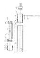
図4ないし図6において、円筒形のカプラー11は、後端部(図において右側の端部)内周に雌ねじ11aを、後端部外周に雄ねじ11bとこの雄ねじ11bに隣接する雄ねじ11cを有している。カプラー11の外周は前端側から図示されないマイクロホンユニット筐体に挿入され、マイクロホンユニット筐体の雌ねじに上記雄ねじ11cがねじ込まれることによってカプラー11と上記マイクロホンユニット筐体が結合される。マイクロホンユニット筐体にはコンデンサーマイクロホンユニットが収納されている。電磁波に対するシールド性を持たせるために、上記マイクロホンユニット筐体、カプラー11はアルミニウムや黄銅合金などの導電材からなる。
4 to 6, the
カプラー11の後端部には、その雌ねじ11aに電池ホルダー20の前端部外周の雄ねじ20aがねじ込まれることによって電池ホルダー20が結合されている。電池ホルダー20は、例えば単三型電池1本が収納される船底状の電池装着凹部21を備えている。この電池装着凹部21の前後方向両端部には、電池のプラス極とマイナス極に接触するプラス側接点とマイナス側接点(図示されず)が設けられ、これらの接点には必要な配線が適宜の手段によって接続されている。電池ホルダー20は電極端子を除き、例えば全体を合成樹脂で形成することができる。
The
電池ホルダー20の後端部外周にも雄ねじ20bが形成されている。この雄ねじ20bには導電材からなる円筒形のコネクタスリーブ30の前端部内周に形成された雌ねじ30aがねじ込まれ、電池ホルダー20とコネクタスリーブ30とが結合されている。コネクタスリーブ30内には出力コネクタ40が挿入され、コネクタスリーブ30を半径方向に貫通した止めねじが出力コネクタ40にねじ込まれることによって出力コネクタ40が固定されている。コネクタスリーブ30の後端部内面には周方向の係合溝31が形成されている。出力コネクタ40はその全体がコネクタスリーブ30内に収まっている。
A
出力コネクタ40は、EIAJ RC−5236「音響機器用ラッチ式丸型コネクタ」に規定されている3ピンタイプの出力コネクタに適合したコネクタが用いられ、その接地ピンである1番ピンは、図示されない導通ねじを介してコネクタスリーブ30と電気的に接続されている。出力コネクタ40は、図示されない平衡シールドケーブルの一端に設けられているプラグと着脱自在となっている。このプラグはコネクタスリーブ30内に差し込まれる部分に接地スリーブを備え、この接地スリーブは平衡シールドケーブルのシールド被覆線と接続されている。上記接地スリーブの一部分にはロック爪が設けられていて、接地スリーブをコネクタスリーブ30に差し込んだときに、コネクタスリーブ30の上記係合溝31に係合するようになっている。ロック爪と係合溝31の係合は、ノブの操作によって解除することができる。出力コネクタ40と平衡シールドケーブルのプラグとの着脱機構は周知であるから、図示していない。
As the
図5、図6に示すように、出力コネクタ40から電池ホルダー20に向かって、これらの外周側に円筒形の電池カバー50が被せられ、電池カバー50の前端部内周に形成された雌ねじ51が前記カプラー11の雄ねじ11bにねじ込まれることによって取り付けられるように構成されている。図5に示すように、電池カバー50の長さは、上記のようにカプラー11にねじ込まれた状態で、電池ホルダー20とコネクタスリーブ30を覆う長さになっている。電池カバー50はカプラー11との螺合を外して後退させることにより、図6に示すように電池ホルダー20の部分を解放することができ、この状態で電池を交換することができる。電池交換後は再び電池カバー50を被せ、カプラー11にねじ込む。
As shown in FIGS. 5 and 6, a
本発明にかかるコンデンサーマイクロホンは、一端側にコンデンサーマイクロホンユニットを収納したマイクロホンユニット筐体を備え他端側にコネクタスリーブが結合された電池ホルダーと、コネクタスリーブ内に保持されていてマイクロホンケーブルの接地スリーブを有するプラグが着脱される出力コネクタと、電池ホルダーを覆う位置と電池ホルダーを開放する位置とで移動可能で電池ホルダーを覆う位置においてマイクロホンユニット筐体と電気的および機械的に結合される導電材からなる円筒状の電池カバーと、コネクタスリーブと電池カバーの間に介在して、コネクタスリーブと電池カバーを面接触により電気的に導通させる弾力性のある導電布とを有し、導電布はコネクタスリーブの外周面側に形成された周溝に落とし込まれ、導電布の外周面に電池カバーの内周面が接触することを最も主要な特徴とする。
Condenser microphone according to the present invention includes a battery holder connector sleeve to the other end coupled with the microphone unit housing that houses the condenser microphone unit at one end, grounding of the microphone cable held in connector sleeve plug and an output connector that is removably has electrical and location position odor Ma Te Lee black phone unit housing to cover the possible battery holder moves to the open position and battery holder covering the batteries holder and mechanically coupled with a sleeve a battery cover cylindrical made of a conductive material which is, interposed between the connector sleeve and the battery cover, the connector sleeve and the battery cover have a conductive cloth resilient for electrically connecting the surface contact, The conductive cloth is dropped into the circumferential groove formed on the outer peripheral surface of the connector sleeve. The inner peripheral surface of the battery cover on the outer peripheral surface of the conductive cloth is the most important feature that contact.
そこで本出願人は、出力コネクタにマイクロホンコードのコネクタを差し込んだときに、導電性の板ばねが電池カバーに接触して電池カバーがマイクロホンコードのシールド被覆線と接続される構成としたコンデンサーマイクロホンを先に提案した。特願2004−209981にかかる発明がそれである。 Accordingly, the applicant of the present invention has a condenser microphone configured such that when the microphone cord connector is inserted into the output connector, the conductive leaf spring contacts the battery cover and the battery cover is connected to the shielded wire of the microphone cord. Proposed earlier. That is the invention according to Japanese Patent Application No. 2004-209981.
本出願人が提案した上記発明によれば、電池カバーにシールド効果をもたせることができるため、電磁波の影響による雑音を低減できる効果がある。しかし、電池カバーをシールドするための板ばねと電池カバーは点接触しているため、昨今の普及が著しい携帯電話から放射される、高い周波数でかつ大きい出力の電磁波に対するシールド効果が十分でなく、至近距離で携帯電話を使用すると雑音を発生することがある。 According to the above-mentioned invention proposed by the present applicant, the battery cover can be provided with a shielding effect, so that it is possible to reduce noise due to the influence of electromagnetic waves. However, since the leaf spring for shielding the battery cover and the battery cover are in point contact, the shielding effect against high-frequency and high-output electromagnetic waves radiated from mobile phones, which have recently become widespread, is not sufficient, When using a mobile phone at a close distance, noise may be generated.
本発明は、かかる従来技術の問題点を解消するためになされたもので、シールド効果をさらに高めるための工夫を加え、特に、高い周波数でかつ大きい出力の電磁波を放射する携帯電話を至近距離で使用したとしても、雑音の発生を防止することができるコンデンサーマイクロホンを提供することを目的とする。 The present invention has been made to solve the problems of the prior art, and has been devised to further enhance the shielding effect. In particular, a mobile phone that emits high-frequency electromagnetic waves at a high frequency at a close range can be obtained. An object of the present invention is to provide a condenser microphone that can prevent generation of noise even if it is used.
本発明にかかるコンデンサーマイクロホンは、一端側にコンデンサーマイクロホンユニットを収納したマイクロホンユニット筐体を備え他端側にコネクタスリーブが結合された電池ホルダーと、上記コネクタスリーブ内に保持されていてマイクロホンケーブルの接地スリーブを有するプラグが着脱される出力コネクタと、上記電池ホルダーを覆う位置と電池ホルダーを開放する位置とで移動可能で電池ホルダーを覆う位置において上記マイクロホンユニット筐体と電気的および機械的に結合される導電材からなる円筒状の電池カバーと、上記コネクタスリーブと電池カバーの間に介在してこれらコネクタスリーブと電池カバーを面接触により電気的に導通させる弾力性のある導電布と、を有してなることを最も主要な特徴とする。 A condenser microphone according to the present invention includes a battery holder having a microphone unit housing that houses a condenser microphone unit on one end side and a connector sleeve coupled to the other end side, and is held in the connector sleeve and grounded on the microphone cable. An output connector to which a plug having a sleeve is attached and detached, and is movable between a position covering the battery holder and a position opening the battery holder, and is electrically and mechanically coupled to the microphone unit housing at a position covering the battery holder. A cylindrical battery cover made of a conductive material, and an elastic conductive cloth interposed between the connector sleeve and the battery cover to electrically connect the connector sleeve and the battery cover by surface contact. The main feature is that
電池ホルダーを覆う電池カバーは、導電布を介してコネクタスリーブと電気的に導通し、かつ、上記導電布は電池カバーとコネクタスリーブに面接触し、加えて、上記導電布は弾力性を有しているため、コネクタスリーブと電池カバーの電気的導通が良好になり、電池カバーによるシールド効果が高まる。したがって、コネクタスリーブと電池カバーを点接触させた前記先行出願にかかる発明と比較すると、携帯電話などの電磁波発生源を至近距離で使用しても、コネクタの部分あるいは電池ホルダーの部分から侵入しようとする電磁波を効果的に遮断し、高周波を原因とする雑音の発生を防止することができる。 The battery cover covering the battery holder is electrically connected to the connector sleeve through the conductive cloth, and the conductive cloth is in surface contact with the battery cover and the connector sleeve. In addition, the conductive cloth has elasticity. Therefore, electrical continuity between the connector sleeve and the battery cover is improved, and the shielding effect by the battery cover is enhanced. Therefore, compared with the invention according to the prior application in which the connector sleeve and the battery cover are in point contact, even if an electromagnetic wave generation source such as a cellular phone is used at a close distance, the connector part or the battery holder part tries to enter. Therefore, it is possible to effectively block the electromagnetic wave to be generated and prevent the generation of noise due to the high frequency.
以下、図1ないし図3を参照しながら本発明にかかるコンデンサーマイクロホンの実施例を説明する。なお、図4ないし図6に示す従来例と同じ構成部分には同じ符号を付した。 Embodiments of a condenser microphone according to the present invention will be described below with reference to FIGS. In addition, the same code | symbol was attached | subjected to the same component as the prior art example shown in FIG. 4 thru | or FIG.
図1ないし図3において、円筒形のカプラー11は、後端部(図において右側の端部)内周に雌ねじ11aを有し、後端部外周に雄ねじ11bとこの雄ねじ11bに隣接する雄ねじ11cを有している。カプラー11はその外周が前端側から図示されないマイクロホンユニット筐体に挿入され、マイクロホンユニット筐体の雌ねじに上記雄ねじ11cがねじ込まれることによってカプラー11と上記マイクロホンユニット筐体が結合される。マイクロホンユニット筐体にはコンデンサーマイクロホンユニットが収納されている。電磁波に対するシールド性を持たせるために、上記マイクロホンユニット筐体、カプラー11はアルミニウムや黄銅合金などの導電材からなり、相互に電気的に導通している。この実施例では、マイクロホンユニット筐体とカプラー11を別部材とし、これらを一体に結合する構成になっているが、これらは一つの部材としてもよい。例えば、カプラー11がマイクロホンユニット筐体を兼ねた構成、すなわちカプラー11がマイクロホンユニット筐体であってもよい。請求項で、「一端側にコンデンサーマイクロホンユニットを収納したマイクロホンユニット筐体」とあるのは、マイクロホンユニット筐体の一端側にコンデンサーマイクロホンユニットが収納されていることを表しており、カプラー11にマイクロホンユニット筐体が結合された構成も含み、カプラー11がマイクロホンユニット筐体として機能する構成も含む。
1 to 3, a
カプラー11の後端部には、その雌ねじ11aに電池ホルダー20の前端部外周の雄ねじ20aがねじ込まれることによって電池ホルダー20が結合されている。電池ホルダー20は、例えば単三型電池1本が収納される船底状の電池装着凹部21を備え、この電池装着凹部21の前端と後端には、外周が円筒面をなす結合部22,24が一体に形成されている。前端側の上記結合部22の外周に上記雄ねじ20aが形成されている。後端側の上記結合部24の外周にも雄ねじ20bが形成されている。上記電池装着凹部21の前後方向両端部には、電池のプラス極とマイナス極に接触するプラス側接点とマイナス側接点(図示されず)が設けられ、これらの接点には必要な配線が適宜の手段によって接続されている。電池ホルダー20は電極端子を除き、上記結合部22,24を含めて例えば全体を合成樹脂で形成することができる。
The
電池ホルダー20の後端側の上記雄ねじ20bには導電材からなる円筒形のコネクタスリーブ30の前端部内周に形成された雌ねじ30aがねじ込まれ、電池ホルダー20とコネクタスリーブ30とが結合されている。コネクタスリーブ30内には出力コネクタ40が挿入され、コネクタスリーブ30を半径方向に貫通した止めねじ(図示されず)が出力コネクタ40にねじ込まれることによって出力コネクタ40が固定されている。コネクタスリーブ30の後端部内面には断面形状が鉤形の係合溝31が一周にわたり形成されている。出力コネクタ40はその全体がコネクタスリーブ30内に収まっている。
A
出力コネクタ40は、例えば、EIAJ RC−5236「音響機器用ラッチ式丸型コネクタ」に規定されている3ピンタイプの出力コネクタに適合したコネクタが用いられ、その接地ピンである1番ピンは、図示されない導通ねじを介してコネクタスリーブ30と電気的に接続されている。出力コネクタ40は、図示されない平衡シールドケーブルの一端に設けられているプラグと着脱自在となっている。このプラグはコネクタスリーブ30内に差し込まれる部分に接地スリーブを備え、この接地スリーブは上記平衡シールドケーブルのシールド被覆線と接続されている。出力コネクタ40に上記プラグを装着することによって、上記接地スリーブとコネクタスリーブ30が電気的に導通するように構成されている。
As the
上記接地スリーブの一部分にはロック爪が設けられていて、接地スリーブをコネクタスリーブ30に差し込んだときに、コネクタスリーブ30の上記係合溝31に係合するようになっている。ロック爪と係合溝31の係合は、ノブなどの操作部材の操作によって解除することができ、これによって上記ケーブル側のコネクタと出力コネクタ40を切り離すことができるようになっている。出力コネクタ40と平衡シールドケーブルのプラグとの着脱機構は周知であるから、図示していない。
A lock claw is provided on a part of the ground sleeve, and when the ground sleeve is inserted into the
図2、図3に示すように、出力コネクタ40から電池ホルダー20に向かって、これらの外周側に円筒形の電池カバー50が被せられ、電池カバー50の前端部内周に形成された雌ねじ51が前記カプラー11の雄ねじ11bにねじ込まれることによって電池カバー50がカプラー11に取り付けられるように構成されている。図5に示すように、電池カバー50の長さは、上記のようにカプラー11にねじ込まれた状態で、電池ホルダー20とコネクタスリーブ30を覆うことができる長さになっている。電池カバー50はカプラー11との螺合を外して後退させることにより、図3に示すように電池ホルダー20の部分を解放することができ、この状態で電池を交換することができる。電池交換後は再び電池カバー50を被せ、カプラー11にねじ込む。
As shown in FIGS. 2 and 3, a
電池カバー50は、上記出力コネクタ40を含むコネクタ部と、電池ホルダー20の部分からマイクロホン内に侵入しようとする高周波の電磁波をシールドする機能を持たせる必要がある。そこで、電池カバー50は、電池ホルダー20を覆う位置において前記マイクロホンユニット筐体と電気的および機械的に結合されるとともに、コネクタスリーブ30とも電気的に接続される必要がある。前述の先行出願にかかる発明では、電池カバーとコネクタスリーブとの電気的結合が点接触によってなされているため、電池カバーのシールド効果が十分でなかった。そこで、図1ないし図3に示す実施例では、電池カバー50のシールド効果を高めるための構成上の工夫がなされており、これが本願発明の特徴的な構成部分となっている。以下、この特徴的な構成部分について説明する。
The
図1ないし図3において、コネクタスリーブ30の外周には周溝32が一周にわたって形成されている。周溝32の断面形状は矩形状である。この周溝32には弾力性のある導電布60がはめ込まれている。導電布60は、例えば、ステンレス鋼からなる導電性の細線が編まれて布状に形成されたもの、あるいは不織布状に形成されたものを切断して細長い帯状にしたもので、厚さ方向にある程度の寸法があって、厚さ方向に弾力性を持っている。かかる導電布60として、例えば、太陽金網株式会社製の導電布SUI−78−5010Tを使用することができる。導電布60は、コネクタスリーブ30の周溝32にほぼ1周にわたり嵌められて巻き付けられている。導電布60の厚さ寸法は上記周溝32の深さ寸法よりも大きく、したがって、導電布60の外周面は周溝32から外周方向外側に突出している。コネクタスリーブ30の周溝32に導電布60を嵌めるに当たり、上記周溝32の底面に、あるいは、導電布60の片面に接着剤を塗布して導電布60を接着すると、組み立てが容易になるとともに、組み立て後の導電布60の脱落を防ぐことができる。ただし、導電性の接着剤を用いることが必須の条件である。
1 to 3, a
図2、図3に示すように、導電布60の外周側から、したがってコネクタスリーブ30の外周側から電池カバー50が被せられている。電池カバー50を被せるに当たり、電池カバー50の内周面で導電布60の外周面が半径方向内側に押され、導電布60は圧縮されて蓄勢される。この蓄勢力で導電布60の外周面は電池カバー60の内周面に圧接している。導電布60と電池ケース50内面との圧接状態は、外見的には面接触である。しかし、厳密に言えば、導電性の細線からなる布状あるいは不織布状の導電布60と円筒状の面をなす電池ケース50との接触であるから、無数の点または線による接触でありかつ単位面積あたりの点接触数または線接触数が極めて多い高密度の接触である。かかる状況の接触は面接触に近いから、請求項の記載では「面接触」とした。
As shown in FIGS. 2 and 3, the
このようにして、コネクタスリーブ30と電池カバー50は導電布60を介して電気的に導通している。電池ホルダー20に電池を装填するときまたは電池を交換するとき、電池ホルダー50の雌ねじ51とカプラー11の雄ねじ11bとの螺合を外し、電池カバー50を図2に示すように後方に移動させ、電池装着凹部21を開放する。電池カバー50を移動させるとき、電池カバー50の内周面と導電布60の外周面とが摺接する。導電布60は、前述のようにステンレス鋼からなる導電性の細線が編まれて布状に形成されたもの、あるいは不織布状に形成されたものである場合、表面の摩擦力が小さい。加えて、導電布60はコネクタスリーブ30の周溝32に嵌められているため、電池カバー50が摺動するときの位置が規制されている。このように、導電布60は、表面が滑りやすいことと本来の位置から外れることがないこととあいまって、電池カバー50が導電布60に対して円滑に摺動することができる。
In this way, the
電池の装填後あるいは電池交換後、電池カバー50をスライドさせて電池ホルダー20を覆い、その雌ねじ51をカプラー11の雄ねじ11bにねじ込んで固定する。この状態で、電池カバー50は導電布60を介してコネクタスリーブ30と電気的に導通し、電池カバー50はまたカプラー11との螺合部によってカプラー11さらにはマイクロホンユニット筐体と電気的に導通する。上記コネクタスリーブ30は、出力コネクタ40に平衡シールドケーブルのプラグを装着することによって、平衡シールドケーブルのシールド被覆線と電気的に導通する。よって、結果的には、平衡シールドケーブルのシールド被覆線およびコネクタスリーブ30と電池カバー50が電気的に導通し、電池カバー50が高周波の電磁波に対するシールド機能を持つことになる。
After loading or replacing the battery, the
そして、導電布60は、無数の点接触あるいは無数の線接触により実質的には面接触と同様の接触状態でコネクタスリーブ30と電池カバー50を電気的に導通させるため、確実に電気的導通を図ることができ、シールド効果を高めることができる。また、導電布60をコネクタスリーブ30の全周にわたる長さをもって配置することにより、周方向全体にわたり均一に導通を図ることができ、シールド効果をさらに高めることができる。特に、携帯電話などの電磁波発生源を上記実施例にかかるコンデンサーマイクロホンの至近距離で使用したとしても、コネクタの部分あるいは電池ホルダー20の部分から侵入しようとする電磁波を効果的に遮断することができ、高周波を原因とする雑音の発生を防止することができる。
導電布60は、その弾力性で圧縮された状態で電池カバー50とコネクタスリーブ30の間に介在しているため、電池カバー50とコネクタスリーブ30の両者を蓄勢力で互いに押圧し、両者間のがたつきを防止することができる利点もある。
The
Since the
図示の実施例では、導電布60はコネクタスリーブ30の長さ方向の1箇所に装着されているが、2箇所あるいはそれ以上の箇所に装着してもよい。
In the illustrated embodiment, the
本発明は、電池で動作するコンデンサーマイクロホンであればどのようなタイプのものにも適用可能である。例えば、内蔵する電池のみを駆動電源とするものはもちろん、内蔵する電池と外部の電源、例えばファントム電源を駆動電源とするものにも適用することができ、いずれのタイプのものにおいても、これまで説明したような所定の効果を得ることができる。 The present invention can be applied to any type of condenser microphone that operates on a battery. For example, it can be applied not only to a built-in battery only as a driving power source but also to a built-in battery and an external power source, for example, a phantom power source as a driving power source. The predetermined effect as described can be obtained.
11 カプラー
20 電池ホルダー
30 コネクタスリーブ
32 周溝
40 出力コネクタ
50 電池カバー
60 導電布
11
Claims (5)
上記コネクタスリーブ内に保持されていてマイクロホンケーブルの接地スリーブを有するプラグが着脱される出力コネクタと、
上記電池ホルダーを覆う位置と上記電池ホルダーを開放する位置とで移動可能で上記電池ホルダーを覆う位置において上記マイクロホンユニット筐体と電気的および機械的に結合される導電材からなる円筒状の電池カバーと、
上記コネクタスリーブと上記電池カバーの間に介在して、上記コネクタスリーブと上記電池カバーを面接触により電気的に導通させる弾力性のある導電布とを有し、
上記導電布は上記コネクタスリーブの外周面側に形成された周溝に落とし込まれ、上記導電布の外周面に上記電池カバーの内周面が接触することを特徴とするコンデンサーマイクロホン。 A battery holder having a microphone unit housing containing a condenser microphone unit at one end and a connector sleeve coupled to the other end;
An output connector that is held in the connector sleeve and to which a plug having a grounding sleeve of a microphone cable is attached and detached;
A cylindrical battery cover composed of the microphone unit housing and electrically and mechanically coupled by conductive material at possible positions for covering the battery holder moves between a position to open position and the battery holder cover the battery holder When,
Interposed between the connector sleeve and the battery cover, the connector sleeve and the battery cover have a conductive cloth resilient for electrically connecting the surface contact,
The condenser microphone is dropped into a circumferential groove formed on the outer peripheral surface side of the connector sleeve, and the inner peripheral surface of the battery cover is in contact with the outer peripheral surface of the conductive cloth .
One end of the battery holders are screwed into the coupler, the other end of the battery holders are screwed to the connector sleeve, said coupler and said battery holders and the connector sleeve is mechanically coupled together according Item 5. The condenser microphone according to Item 4.
Priority Applications (2)
| Application Number | Priority Date | Filing Date | Title |
|---|---|---|---|
| JP2005011283A JP4562032B2 (en) | 2005-01-19 | 2005-01-19 | Condenser microphone |
| US11/333,279 US7801316B2 (en) | 2005-01-19 | 2006-01-18 | Capacitor microphone |
Applications Claiming Priority (1)
| Application Number | Priority Date | Filing Date | Title |
|---|---|---|---|
| JP2005011283A JP4562032B2 (en) | 2005-01-19 | 2005-01-19 | Condenser microphone |
Publications (3)
| Publication Number | Publication Date |
|---|---|
| JP2006203407A JP2006203407A (en) | 2006-08-03 |
| JP2006203407A5 JP2006203407A5 (en) | 2007-11-29 |
| JP4562032B2 true JP4562032B2 (en) | 2010-10-13 |
Family
ID=36683920
Family Applications (1)
| Application Number | Title | Priority Date | Filing Date |
|---|---|---|---|
| JP2005011283A Expired - Fee Related JP4562032B2 (en) | 2005-01-19 | 2005-01-19 | Condenser microphone |
Country Status (2)
| Country | Link |
|---|---|
| US (1) | US7801316B2 (en) |
| JP (1) | JP4562032B2 (en) |
Families Citing this family (11)
| Publication number | Priority date | Publication date | Assignee | Title |
|---|---|---|---|---|
| JP4925818B2 (en) * | 2006-08-11 | 2012-05-09 | 株式会社オーディオテクニカ | Microphone connector and microphone equipped with the same |
| KR100819281B1 (en) * | 2006-10-30 | 2008-04-02 | 삼성전자주식회사 | Battery cover grounding device for portable terminal |
| US20080260194A1 (en) * | 2007-02-07 | 2008-10-23 | Donald Bruce Pooley | Microphone sleeve |
| JP4972473B2 (en) * | 2007-06-14 | 2012-07-11 | 株式会社オーディオテクニカ | Condenser microphone |
| JP2010226441A (en) * | 2009-03-24 | 2010-10-07 | Audio Technica Corp | Condenser microphone |
| JP5404220B2 (en) * | 2009-07-09 | 2014-01-29 | 株式会社オーディオテクニカ | Condenser microphone |
| JP2011023857A (en) * | 2009-07-14 | 2011-02-03 | Audio Technica Corp | Condenser microphone |
| US8243974B2 (en) * | 2010-04-08 | 2012-08-14 | Mipro Electronics Co., Ltd. | Wireless microphone |
| JP5777293B2 (en) * | 2010-04-30 | 2015-09-09 | 株式会社オーディオテクニカ | Condenser microphone |
| JP5557279B2 (en) * | 2010-05-28 | 2014-07-23 | 株式会社オーディオテクニカ | Battery room for condenser microphones |
| JP5586054B2 (en) * | 2010-08-27 | 2014-09-10 | 株式会社オーディオテクニカ | Microphone connector |
Citations (8)
| Publication number | Priority date | Publication date | Assignee | Title |
|---|---|---|---|---|
| JPS56137585U (en) * | 1980-03-19 | 1981-10-17 | ||
| JPS5963584U (en) * | 1982-10-20 | 1984-04-26 | 東亜特殊電機株式会社 | microphone |
| JPS5981135U (en) * | 1982-11-22 | 1984-06-01 | 東亜特殊電機株式会社 | microphone |
| JPS62220885A (en) * | 1986-03-17 | 1987-09-29 | エド コ−ポレ−シヨン/ウエスタン デイヴイジヨン | Linear row type converter assembly |
| JPH0327420U (en) * | 1989-07-28 | 1991-03-19 | ||
| JPH0347277U (en) * | 1989-09-14 | 1991-05-01 | ||
| JPH0386577U (en) * | 1989-12-21 | 1991-09-02 | ||
| JP2001103591A (en) * | 1999-09-30 | 2001-04-13 | Matsushita Electric Ind Co Ltd | Microphone and video camera |
Family Cites Families (9)
| Publication number | Priority date | Publication date | Assignee | Title |
|---|---|---|---|---|
| US3564416A (en) * | 1968-03-29 | 1971-02-16 | Edward G Price | Cordless,self-contained microphone transmitter |
| JPS5981135A (en) | 1983-07-26 | 1984-05-10 | Seikei Giken:Kk | Lamination apparatus |
| US4684762A (en) * | 1985-05-17 | 1987-08-04 | Raychem Corp. | Shielding fabric |
| US5160806A (en) * | 1989-11-29 | 1992-11-03 | Nec Corporation | Electromagnetic shielding member and electromagnetic shielding case |
| US5767449A (en) * | 1996-07-09 | 1998-06-16 | Yazaki Corporation | Method and apparatus for grounding a RFI/EMI shielding tube |
| JPH1047277A (en) | 1996-07-31 | 1998-02-17 | Matsushita Refrig Co Ltd | Rotary compressor |
| JP3899185B2 (en) | 1998-05-28 | 2007-03-28 | 株式会社オーディオテクニカ | Microphone output connector device |
| US6463159B1 (en) * | 2002-01-16 | 2002-10-08 | Taky Electronics Co., Ltd. | Battery case structure of microphone of loudspeaker system |
| US9243993B2 (en) * | 2005-03-17 | 2016-01-26 | Sysmex Corporation | Sample analyzer and sample analyzing method |
-
2005
- 2005-01-19 JP JP2005011283A patent/JP4562032B2/en not_active Expired - Fee Related
-
2006
- 2006-01-18 US US11/333,279 patent/US7801316B2/en not_active Expired - Fee Related
Patent Citations (8)
| Publication number | Priority date | Publication date | Assignee | Title |
|---|---|---|---|---|
| JPS56137585U (en) * | 1980-03-19 | 1981-10-17 | ||
| JPS5963584U (en) * | 1982-10-20 | 1984-04-26 | 東亜特殊電機株式会社 | microphone |
| JPS5981135U (en) * | 1982-11-22 | 1984-06-01 | 東亜特殊電機株式会社 | microphone |
| JPS62220885A (en) * | 1986-03-17 | 1987-09-29 | エド コ−ポレ−シヨン/ウエスタン デイヴイジヨン | Linear row type converter assembly |
| JPH0327420U (en) * | 1989-07-28 | 1991-03-19 | ||
| JPH0347277U (en) * | 1989-09-14 | 1991-05-01 | ||
| JPH0386577U (en) * | 1989-12-21 | 1991-09-02 | ||
| JP2001103591A (en) * | 1999-09-30 | 2001-04-13 | Matsushita Electric Ind Co Ltd | Microphone and video camera |
Also Published As
| Publication number | Publication date |
|---|---|
| JP2006203407A (en) | 2006-08-03 |
| US20060159294A1 (en) | 2006-07-20 |
| US7801316B2 (en) | 2010-09-21 |
Similar Documents
| Publication | Publication Date | Title |
|---|---|---|
| JP4562032B2 (en) | Condenser microphone | |
| JP4683996B2 (en) | Condenser microphone | |
| TW201721997A (en) | Magnetic surface contacts | |
| JP4157819B2 (en) | Microphone output connector | |
| US8204259B2 (en) | Condenser microphone | |
| US9832556B2 (en) | Microphone device and microphone stand | |
| US7526097B2 (en) | Condenser microphone | |
| US20060045302A1 (en) | Condenser microphone | |
| JP5492036B2 (en) | Gooseneck microphone | |
| KR20140118120A (en) | Antenna device for portable terminal | |
| US7447326B2 (en) | Condenser microphone | |
| US7599505B2 (en) | Condenser microphone | |
| US8070518B2 (en) | Connector for capacitor microphone | |
| CN203056227U (en) | High and low frequency mixed connector and assembly thereof | |
| JP4619982B2 (en) | Condenser microphone | |
| US7160153B1 (en) | Electrical connector | |
| JP4469704B2 (en) | Condenser microphone | |
| JP4417801B2 (en) | Condenser microphone | |
| JP4345892B2 (en) | Microphone and microphone shielding parts | |
| JP4516819B2 (en) | Condenser microphone | |
| CN217656059U (en) | Wireless earphone | |
| CN216355100U (en) | Earphone socket | |
| JP4074141B2 (en) | Dummy built-in coaxial connector | |
| JP5119048B2 (en) | Power supply for condenser microphone | |
| JP6484832B2 (en) | Microphone, microphone housing |
Legal Events
| Date | Code | Title | Description |
|---|---|---|---|
| A521 | Request for written amendment filed |
Free format text: JAPANESE INTERMEDIATE CODE: A523 Effective date: 20071016 |
|
| A621 | Written request for application examination |
Free format text: JAPANESE INTERMEDIATE CODE: A621 Effective date: 20071016 |
|
| A977 | Report on retrieval |
Free format text: JAPANESE INTERMEDIATE CODE: A971007 Effective date: 20100422 |
|
| A131 | Notification of reasons for refusal |
Free format text: JAPANESE INTERMEDIATE CODE: A131 Effective date: 20100506 |
|
| A521 | Request for written amendment filed |
Free format text: JAPANESE INTERMEDIATE CODE: A523 Effective date: 20100628 |
|
| TRDD | Decision of grant or rejection written | ||
| A01 | Written decision to grant a patent or to grant a registration (utility model) |
Free format text: JAPANESE INTERMEDIATE CODE: A01 Effective date: 20100721 |
|
| A01 | Written decision to grant a patent or to grant a registration (utility model) |
Free format text: JAPANESE INTERMEDIATE CODE: A01 |
|
| A61 | First payment of annual fees (during grant procedure) |
Free format text: JAPANESE INTERMEDIATE CODE: A61 Effective date: 20100721 |
|
| FPAY | Renewal fee payment (event date is renewal date of database) |
Free format text: PAYMENT UNTIL: 20130806 Year of fee payment: 3 |
|
| R150 | Certificate of patent or registration of utility model |
Free format text: JAPANESE INTERMEDIATE CODE: R150 |
|
| LAPS | Cancellation because of no payment of annual fees |