JP4560884B2 - Human body cleaning device - Google Patents
Human body cleaning device Download PDFInfo
- Publication number
- JP4560884B2 JP4560884B2 JP2000126961A JP2000126961A JP4560884B2 JP 4560884 B2 JP4560884 B2 JP 4560884B2 JP 2000126961 A JP2000126961 A JP 2000126961A JP 2000126961 A JP2000126961 A JP 2000126961A JP 4560884 B2 JP4560884 B2 JP 4560884B2
- Authority
- JP
- Japan
- Prior art keywords
- water
- flow rate
- cleaning
- flow
- washing
- Prior art date
- Legal status (The legal status is an assumption and is not a legal conclusion. Google has not performed a legal analysis and makes no representation as to the accuracy of the status listed.)
- Expired - Fee Related
Links
Images


Description
【0001】
【発明の属する技術分野】
本発明は、洗浄水を吐水孔から人体に吐水する人体洗浄装置に関する。
【0002】
【従来の技術】
この種の人体洗浄装置、例えば人体局部を洗浄する局部洗浄装置は、人体局部を洗浄水で清潔にできることから急速に普及している。そして、近年では、その付加価値向上のため、排便誘発機能の向上や、多様な洗浄感を得ること等を目的に、種々の提案がなされている。例えば、国際公開WO99/53150号公報に記載の局部洗浄装置では、洗浄水通水状況の繰り返し変動を高周波数領域で起こしつつ洗浄水を吐水することで、脈動流や断続流の状態の洗浄水吐水としている。そして、こうすることで、給水洗浄水流量(詳しくは、単位時間当たりの給水洗浄水流量)が同じでも、吐水から受ける刺激感を強弱調整可能としている。
或いは、給水洗浄水流量を低減しても、低減前の給水洗浄水流量の場合と同程度の刺激感を与えることを可能とし、見かけの洗浄水流量を増大させている。
【0003】
【発明が解決しようとする課題】
しかし、上記公報記載の局部洗浄装置は、脈動流や断続流での洗浄水吐水を実現する新たな構成の吐水装置を提供するものの、使用者が求める洗浄感は多岐に亘るため、次のような問題が指摘されるに至った。
【0004】
局部洗浄の都度に求められる洗浄感は、常に一律であるとは限らない。例えば、同一の使用者であっても、下痢気味であったり便秘気味であることもあり、前者と後者の場合では局部洗浄に際して求める洗浄感は相違する。痔疾患を患ったときの洗浄感も相違する。また、ビデ洗浄であれば、出血やおりものの程度等によっても、求める洗浄感は相違する。
【0005】
ところで、洗浄感には種々のものが含まれるが、場合によっては(例えば、痔疾患時や生理時のビデ洗浄時)、たっぷりとした水量の洗浄水を給水して吐水し、たっぷりの水量の洗浄水を実際に局部に着水させてこれを洗浄することが優先されることがある。そして、このように、実際の着水洗浄水量が多い場合には、その着水洗浄水から受ける水量感(たっぷり感)が体感として支配的となり易いので、刺激感といった他の洗浄感を大きく加味する必要は少なくなりがちである。その反面、給水洗浄水流量自体を少なくして実際の着水洗浄水量を低減させるような場合は、少ない洗浄水流量で刺激感を高めて見かけの洗浄水流量(着水洗浄水量)を増大させる必要性が高い。しかしながら、上記の従来の局部洗浄装置では、これらの点に対する対処が十分ではなく、さらなる改善の余地が残されていた。
【0006】
本発明は、上記課題を解決するためになされたものであり、給水洗浄水流量に応じた洗浄感の多様化を図ることを目的とする。
【0007】
【課題を解決するための手段およびその作用・効果】
かかる課題の少なくとも一部を解決するため、本発明の人体洗浄装置は、
給水された洗浄水を吐水孔から人体に吐水する人体洗浄装置であって、
前記吐水孔に通水される洗浄水の流量を設定する流量設定手段と、
前記給水された洗浄水を、前記流量設定手段により設定された設定流量に流量調整した上で前記吐水孔に通水する流量調整手段と、
前記吐水孔に通水される洗浄水の流速と圧力のいずれかに規則的な変動を生じさせて、前記吐水孔に通水される洗浄水の流れに規則的な変動を起こす変動発生手段と、
前記変動発生手段を制御して、前記変動の規則性を前記設定流量に応じて変更する変動制御手段とを備え、
該変動制御手段は、前記設定流量が小さいほど前記変動の振幅の可変幅を広くしつつ、該可変幅の範囲で前記変動の振幅を前記設定流量ごとに変更する振幅変更手段を有する、
ことを特徴とする。
【0008】
上記構成を有する本発明の人体洗浄装置では、給水洗浄水を吐水孔から吐水するに当たり、給水洗浄水を設定流量に流量調整した上で吐水孔に通水し、その通水洗浄水の流れに規則的な変動を生じさせる。そして、この変動が生じた洗浄水の流れの状態で洗浄水を吐水孔から吐水して洗浄水吐水を周期的なものとする。
しかも、この洗浄水の流れの変動の規則性、例えば、変動周期や変動振幅等を設定流量に応じて変更するので、設定流量による水量感を与えつつ、変動の規則性に起因して体感する洗浄感(例えば、刺激感)を、設定流量に応じて種々変更制御するものとでき、その多様化をもたらす。
【0009】
この場合、この規則性の変更に際しては、変動規則性の変更程度が異なるように設定流量に応じてこの規則性を変更するようにできる。例えば、設定流量が小さく給水洗浄水流量が少ないほど、変動振幅の変更可変幅を広くするようにすれば、給水洗浄水流量が少ない給水状態において、洗浄水の流れの変動の規則性に起因して体感する洗浄感を大きく可変することができる。設定流量が大きい場合には、給水洗浄水流量が多い給水状態としてたっぷりとした水量感を与えつつ、上記の変動振幅の可変幅を狭くして洗浄感の調整幅を狭くすることができる。
【0010】
この場合、吐水洗浄水から受ける使用者の洗浄感を設定するようにし(例えば、刺激感の強弱設定)、設定流量が同一である状況下においては、設定刺激感が強くなるほど変動振幅を大きくするものとすることができる。
こうすれば、設定された刺激感を確実に得ることができる。
【0011】
ところで、上記の本発明の人体洗浄装置のように、洗浄水の流れに変動を起こしこの洗浄水を吐水孔から吐水すると、周期的な洗浄水吐水は次のような形態となる。
吐水孔からの吐水洗浄水は、吐水孔に導かれた洗浄水の流れの状態が反映される。吐水孔に一律な流れ(連続流)で洗浄水が導かれれば、吐水孔からは洗浄水は連続的に吐水され、連続流の吐水形態となる。しかし、流れに変動を来して洗浄水が吐水孔に導かれると、この変動が反映した周期的な吐水形態となる。本発明では、吐水孔には脈動流の状態で洗浄水が導かれ、吐水孔からの吐水形態は、この脈動流が反映して吐水水量が増減するような脈動をもつものとなる。このような吐水形態を瞬間的に捕らえると、後に詳述するように、吐水水量が多い時に吐水された洗浄水が水塊となって、この水塊が吐水水量が少ないときに吐水された洗浄水で繋がったようなものとなる。そして、脈動流が反映した吐水水量の増減幅は上記した変動振幅に他ならないので、変動振幅変更により、水塊の生成程度(水塊水量)を可変でき、この水塊の着水による洗浄感、即ち変動の規則性に起因して体感する洗浄感を、設定流量に応じて可変できる。例えば、刺激感の強弱を、設定流量が少ない場合には大きく変動させたり、設定流量が多い場合には小さくしか変動させないようにできる。
【0012】
また、変動周波数や変動振幅といった変動の規則性を規則的或いは不規則的にもしくはゆらぎ周期的に変更するようにすることもでき、こうすれば、流れの変動規則性の変更により脈動流での洗浄水吐水の様子を、設定流量に応じて変更できる。よって、この脈動流での洗浄水吐水に基づく洗浄感が規則的或いは不規則的もしくはゆらぎ周期的に変化するので、それぞれの設定流量での洗浄水給水に基づく洗浄時において、洗浄感の多様化を図ることができる。
【0013】
刺激感の強弱変化に着目すると次の利点がある。流れの変動規則性(例えば、変動周波数、変動振幅)を規則的に変更すれば、脈動流での洗浄水吐水を人体局部に当てることで刺激に規則変化を与えることができる。しかも、この刺激の規則変化の幅を設定流量に応じて可変できる。よって、刺激感の規則的な強弱繰り返しによるマッサージ効果を、各設定流量での洗浄時において好適に発揮できるので、排便の促進を図ることができる。
一方、この刺激が不規則的に変化すれば、刺激の変化の様子を予測しにくいことから、洗浄時の単調感を緩和できると共に、後述のように無意識下での局部洗浄の際の排便促進を図ることができる。
【0014】
上記の構成を有する本発明の人体洗浄装置は、以下の態様を採ることもできる。即ち、
前記変動発生手段を、前記流れの変動の規則性が同一である状況下では、前記変動が生じた洗浄水の流れの状態での洗浄水吐水に基づく吐水状態変化を人体が刺激変化として認識しないように、前記流れの変動を誘起する変動誘起手段を有するものとすることができる。
【0015】
こうすれば、上記したように脈動流での洗浄水吐水に基づく吐水状態変化やこの脈動流での洗浄水吐水とするための流れの変動を、その変動の規則性が同一である状況下では、人体が刺激変化として認識しないようにできる。例えば、変動周波数や変動振幅が同じ状況下では、この変動周波数或いは変動振幅に基づく脈動流での吐水であることを、人体が刺激変化として認識しないようにできる。よって、脈動流での洗浄水吐水であるために上記のように水塊が繋がった吐水状態であることや、水塊が次々と人体表皮に当たっているということを人体に感じさせないまま、洗浄水の流れに変動を起こすことができる。このため、脈動流での洗浄水吐水であっても、使用者にはあたかも連続した流れで洗浄水吐水を受けているような感じを与えることができる。従って、本発明で実現した脈動流での洗浄水吐水を、洗浄水による連続的な洗浄が求められる通常のお尻洗浄やビデ洗浄にも好適に用いることができ、その際に違和感や不快感を与えることがない。しかも、設定流量が異なるものであっても、このような洗浄に適用できる。
【0016】
脈動流での洗浄水吐水に基づく吐水状態変化を人体が認識しないよう誘起するに当たっては、次のような手法を採ることができる。脈動流での洗浄水吐水の周期が約0.3秒程度の周期であると、脈動流の洗浄水吐水を受けることによる刺激変化(即ち、変動振幅に基づく刺激変化)を人体が比較的明確に知覚することができるから、上記の脈動流の洗浄水吐水の周期、即ちこのような吐水を引き起こすための洗浄水の流れの変動を約0.2秒以下の短周期で起きるようにすることが好ましい。脈動流での洗浄水吐水が約3Hz以下の周波数でなされると、その刺激変化を人体が明確に知覚することができ、これを越える周波数であると刺激変化として知覚できない。つまり、刺激変化を知覚するに当たっては不感帯領域(不感帯周波数)がある。よって、吐水状態変化を人体が認識(知覚)しないようにするには、上記の洗浄水の流れの規則的な変動を不感帯周波数に含まれる約5Hz以上の周波数で起きるようにすることが好ましい。そして、この変動を商用電源の周波数で起こせば、こうした変動を起こすための機器の制御が容易となり好ましい。
【0017】
ところで、洗浄水の着水箇所(洗浄領域)は、例えば局部洗浄にあっては、肛門や女性局部となるが、これらの局部はデリケートな表皮部分であり、痔疾患や生理等により刺激に対して過敏な場合がある。しかも、局部によって過敏となる程度は異なる。よって、上記した不感帯領域を約5Hz以上の周波数領域に固定するのではなく、洗浄対象局部に応じて最低周波数を調整するようにすることもできる。更には、この不感帯領域のうちの低周波数領域では、使用者は、通常ならば局部洗浄に際して刺激変化を認識しないが、痔疾患や生理等により、この低周波数領域での洗浄水吐水に刺激変化を僅かに認識するようなことが起き得る。よって、この低周波数領域を不感帯領域の境界領域として設定し、この境界領域以上の周波数領域を確実な不感帯領域とするようにすることもできる。なお、刺激変化に対する認識を確実に起こさないようにするために、次のようにすることもできる。つまり、上記した境界領域を上記約5Hzから約60Hzもしくは約80Hzまでに設定し、この周波数領域の境界領域を越える周波数領域を確実な不感帯領域とする。
【0018】
このように周波数を設定した上で、設定流量に応じて変動振幅を可変することもできるので、各設定流量での吐水洗浄において、刺激変化を知覚させないまま洗浄できる。
【0019】
上記した変動を起こすための前記変動発生手段を、
前記給水経路の一部をなすシリンダと、
該シリンダ内で往復動し、その往復動により洗浄水の流れに脈動を起こして洗浄水を前記シリンダ下流に圧送するプランジャと、
該プランジャを往復駆動させる電磁ソレノイドと、
該電磁ソレノイドを励磁する励磁手段と、
前記シリンダに設けられ、下流側への洗浄水の通過を許容する逆止弁とを有するものとすることができる。
こうすれば、電磁ソレノイドの励磁制御を通してプランジャをシリンダ内で往復動させ、これにより脈動を洗浄水の流れに起こして洗浄水を脈動流の状態で圧送することができる。
【0020】
しかも、下流側にしか逆止弁を備えず、シリンダの上流側には逆止弁を有しないので、脈動流での圧送時に、プランジャの移動状況によらずにシリンダ内に洗浄水を常時導いて洗浄水を圧送する。よって、特段の構成やプランジャ移動制御を用いなくても、脈動流での洗浄水圧送に際して流量ゼロの状況を起こさないようにできる。
【0021】
また、前記変動制御手段を、
前記励磁手段を制御して、前記電磁ソレノイドの励磁強度又はデューティ比の少なくとも一方を変更するものとすることができる。
こうすれば、変動振幅を確実に変更できる。
【0022】
この場合、設定刺激感が強くなるほど或いは設定流量が少なくなるほど、励磁周波数を低減変更するものとすることもできる。
【0023】
また、洗浄水の流れに規則的な変動を生じさせて吐水するものの、変動発生を起こす機器までについては、一定の給水洗浄水流量で給水すれば足りる。よって、次の利点がある。
【0024】
一般に、人体局部に洗浄水を吐水する人体洗浄装置、即ち局部洗浄装置では、洗浄水が局部に当たる際の不快感を緩和するために、温水化した洗浄水を吐水する。この温水化を図るため、水路系には瞬間式熱交換機器、或いは貯湯式温水機器が設置される。これら温水化機器を変動発生を起こす機器より上流側に配置した場合、これら温水化機器を給水洗浄水流量一定化で運転(熱交換)できる。よって、熱交換器の運転条件が一定となり、その制御の簡略化を図ることができる。
【0025】
【発明の他の態様】
本発明は、次のような他の態様を採ることもできる。即ち、
前記吐水孔からの洗浄水吐水の開始指令を出力する手段を備え、
前記変動制御手段は、前記開始指令を受けて前記変動発生手段の制御を開始する手段を有するものとすることができる。
こうすれば、開始指令を受けて変動発生手段の制御を開始することにより、吐水開始当初から、設定流量による水量感を与えつつ、その設定流量に応じた洗浄感(例えば、刺激感)を確保して快適な洗浄状況を使用者に提供することができる。
【0026】
また、給水洗浄水を給水状態のまま前記吐水孔から吐水する手段を備え、
前記変動制御手段は、前記通水洗浄水の流れに規則的な変動を生じさせた状態での洗浄水吐水と前記給水状態のままの洗浄水吐水とを選択実行する手段を有するものとしたり、この両洗浄水吐水を周期的に切替実行する手段を有することができる。
こうすれば、二つの洗浄水吐水の選択実行により、使用者に洗浄の単調感を与えないようにすることができる。また、二つの吐水状態の選択実行もしくは切替実行により、各吐水状態での異なる洗浄感を交互に与えたり、いずれか一方の吐水状態による洗浄感を使い分けることができるので、洗浄の多様化や洗浄の単調感緩和を図ることができる。
【0027】
更に、複数の前記吐水孔を異なる吐水対象ごとに有すると共に、前記吐水孔に至る管路を前記吐水孔ごとに有する吐水部と、
前記変動発生手段により規則的な変動を生じさせた洗浄水の供給先を、前記吐水部の複数の前記管路のいずれかに切り替える切替手段とを備えるものとすることができる。
また、前記吐水孔とこれに至る管路とを有し、異なる吐水対象ごとに用意された複数の吐水部と、
前記変動発生手段により規則的な変動を生じさせた洗浄水の供給先を、前記複数の吐水部のうちのいずれかの前記吐水部の前記管路に切り替える切替手段とを備えるものとすることができる。
【0028】
こうすれば、異なる吐水対象に洗浄水を吐水してこれを洗浄するに際し、各吐水対象を、設定流量による水量感を与えつつ、その設定流量に応じた洗浄感(例えば、刺激感)で洗浄することができる。この場合、異なる吐水対象ごとに変動の周波数や変動振幅可変幅を設定できる。例えば、既述した境界領域も考慮して、局部洗浄装置においてお尻洗浄では約71Hz、柔らか洗浄で約71Hz、ビデ洗浄では約83Hzのように周波数を変更するというように、各種の洗浄形態の特性に合わせて周波数を設定してもよい。或いは、ビデ洗浄をお尻洗浄に比して各設定流量に応じた変動振幅可変幅を狭くしたりすることもできる。
【0029】
【発明の実施の形態】
次に、本発明に係る人体洗浄装置を人体局部を洗浄する局部洗浄装置に適用した実施の形態を実施例に基づき説明する。図1は、便器に装着した状態の実施例の局部洗浄装置10を表す概略斜視図、図2は、局部洗浄装置の概略構成を水路系を中心に表したブロック図、図3は、この水路系に配設されたアキュムレータ73の概略構成を示す断面図、図4は、同じく水路系に配設された波動発生機器74の構成を表す断面図である。また、図5は、この波動発生機器74による洗浄水の流れの様子を説明する説明図、図6は、制御系の概略構成を表すブロック図である。
【0030】
図示するように、局部洗浄装置10は、便器BTの後部上面に固定される本体部12と、洗浄動作や乾燥動作等を遠隔操作するための遠隔操作装置14とを有する。本体部12は、便器開口部側に、便座18並びに便蓋20を開閉自在に備える。また、この本体部は、便器の側方に袖部22を有すると共に、洗浄水を洗浄局部に吐水する洗浄ノズル24を有するノズル装置40(図8参照)の他、後述の種々の機能部品を収納している。
【0031】
遠隔操作装置14は、その前面に、排便時に常用される種々のボタンを備え、操作されたボタンに対応した信号(光信号)を発するようにされている。例えば、お尻洗浄が所望される際に操作されるお尻洗浄ボタン(図示省略)が操作されると、その旨の信号が発せられ、この信号は本体部12の側で受信される。そして、この信号を受けて、お尻洗浄が開始される。つまり、図示しないお尻洗浄ボタン、やわらか洗浄ボタン、ビデ洗浄ボタンの各ボタンは、当該ボタンの操作を経てそれぞれの洗浄が開始されることから、洗浄水吐水の開始指令を出力するものとしてとして機能する。この他、遠隔操作装置14は、洗浄動作の停止を指示する停止ボタンや、乾燥実行を指示する乾燥ボタン、水勢を強弱設定する水勢設定ボタン、ムーブ洗浄の実行を指示するムーブ設定ボタン、刺激感の強弱を設定指示するためのソフト・ハード設定ボタン等の種々のボタンを有する。この水勢設定ボタンは、水勢の強弱設定を通して吐水孔への通水洗浄水流量を大小設定する(本実施例では5段階に設定する)。刺激感は5段階の設定が可能であり、ソフト・ハード設定ボタンは、ソフト設定ボタン或いはハード設定ボタンの操作ごとに刺激感を一段階ずつ変更する。例えば、現在の刺激感が2段階目であれば、1回のソフト設定ボタンの操作で1段階目の刺激感にソフト化するよう指示する。一方、この状態でハード設定ボタンが2回操作されれば、刺激感を2段階ハード化し、4段階目の刺激感とするよう指示する。
【0032】
袖部22は、その上面に、本局部洗浄装置の動作状況等を表示する表示部28と、開閉自在なカバー29とを有する。なお、この表示部には、上記の遠隔操作装置14から発せられた光信号を受光する受光部が組み込まれている。また、このカバー29の一部は、着座人体を検出するための着座センサSS10(図6参照)からの光を選択的に透過させるよう着色された光透過窓29aとされている。また、この袖部22のカバー下方には、局部洗浄に必要な最低限のボタンが設けられており、遠隔操作装置14が電池切れ等で操作不能なときでも袖部のボタン操作で局部洗浄を行うことができるようにされている。
【0033】
本実施例の局部洗浄装置10は、遠隔操作装置14や袖部22のボタン操作に応じた洗浄動作・乾燥動作等を行うため、以下の水路系構成並びに制御系構成を有する。図2に示すように、本局部洗浄装置の水路系は、図示しない外部の給水源側から、入水側弁ユニット50と熱交換ユニット60と流調弁65と波動発生ユニット70とを備える。そして、この波動発生ユニット70の下流の流路切換弁71を経て洗浄ノズル24に洗浄水が通水される。流路切換弁71は、洗浄ノズル24の後端に一体に設置されており、後述のように波動発生機器74から送られた脈動流の洗浄水の通水先を、洗浄ノズル24のお尻洗浄用、やわらか洗浄用およびビデ洗浄用の各ノズル流路に切り換える。これにより、洗浄水は、波動発生ユニット70による変動を保ったまま、洗浄ノズルのお尻吐水孔、やわらか吐水孔、ビデ吐水孔の各吐水孔から洗浄水が吐水される。上記の各ユニットは、波動発生ユニット70を挟んだ上流側・下流側給水管路で接続されている。即ち、入水側弁ユニット50と熱交換ユニット60は、上流側給水管路51で接続され、波動発生ユニット下流の流路切換弁71は、下流側給水管路72で接続されている。
【0034】
上流側給水管路51は、本局部洗浄装置に給水源(水道管)から洗浄水(水道水)を直接給水すべく入水側弁ユニット50に配管されている。この上流側給水管路51に導かれた洗浄水は、入水側弁ユニット50のストレーナ52でのごみ等の捕捉を経て、逆止弁53、調圧弁54に流れ込む。そして、調圧弁下流の電磁弁55にて管路が開かれると、洗浄水は、調圧弁54で所定の圧力(1次圧:約0.098MPa{約1.0kgf/cm2 })に調圧された状態で、瞬間加熱方式の熱交換ユニット60に流入する。このように調圧を受けて流入する洗浄水流量は、約100〜500cc/min程度となるようにされている。なお、上流側給水管路51を、便器洗浄用の洗浄水を貯留する洗浄水タンク(図示省略)から分岐して入水側弁ユニット50に配管することもできる。
【0035】
この入水側弁ユニット50から熱交換ユニット60に至る間の上流側給水管路51には、リリーフ弁56を介在させた第1洗浄水導出管路56aが配設されている。この第1洗浄水導出管路56aは、リリーフ弁上流側の管路圧力が何らかの原因で上昇してリリーフ弁56により管路が開かれると、上流側給水管路51内の洗浄水を外部に導出する。
【0036】
上記した入水側弁ユニット下流の熱交換ユニット60は、ヒータ61を内蔵する熱交換部62を備える。このヒータ61またはその近傍には、図示しないバイメタルスイッチや温度ヒューズが装着されており、熱交換ユニット60の異常加熱回避が図られている。このヒータ61は、熱応答性が良好なタングステン−モリブデンを用いたヒータ構成とされている。よって、熱交換部62はこのヒータ61による洗浄水の瞬間加熱が可能な容量であればよくなり、熱交換部、延いては熱交換ユニット全体の小型化が可能である。
【0037】
そして、この熱交換ユニット60は、熱交換部62へ流入する洗浄水の温度と熱交換部62から流出する洗浄水の温度を入水温センサSS16aと出水温センサSS16bで検出しつつ、ヒータ61で洗浄水を設定温度の洗浄水に温水化する。そして、このようにして温水化された洗浄水は、流調弁65により流量調整を受けた上で、後述の波動発生ユニット70に流入する。
【0038】
また、この熱交換ユニット60は、熱交換部内水位を検出するフロートスイッチSS18を備え、その信号により、空焚きが回避されるようになっている。また、熱交換ユニット60は、バキュームブレーカ63を備え、このバキュームブレーカ63により、熱交換部下流側からの洗浄水逆流を防止するようになっている。
【0039】
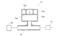
波動発生ユニット70は、その上流側からアキュムレータ73と、波動発生機器74とを有する。このアキュムレータ73は、図3に示すように、波動発生機器74より上流の上流側給水管路51に接続されたハウジング73aと、ハウジング内のダンパ室73bに配置されたダンパ73cと、このダンパに付勢力を及ぼすスプリング73dとを有する。よって、アキュムレータ73は、波動発生機器74の上流において、上流側給水管路51の水撃を低減する。このため、熱交換部62の洗浄水温度分布に及ぼす水撃の影響を緩和でき、吐水洗浄水の温度を安定化することができる。
【0040】
波動発生機器74は、図4に示すように、上流側・下流側給水管路51、72に接続されるシリンダ74aにプランジャ74bを摺動自在に備える。そして、このプランジャ74bを電磁コイル(脈動発生コイル)74cの励磁制御により上流側・下流側に進退させる。プランジャ74bは、脈動発生コイル74cの励磁により図示する原位置(プランジャ原位置)から下流側に移動するが、コイル励磁が消えると、復帰スプリング74eの付勢力を受けて原位置に復帰する。この際、緩衝スプリング74dでプランジャ74bの動作が緩衝される。
【0041】
プランジャ74bは、その内部に鋼球とスプリングからなる逆止弁74fを有するので、プランジャ原位置から下流側への移動の際には、シリンダ74a内の洗浄水を加圧して下流側給水管路72に押し流す。この際、プランジャ原位置は一定であることから、一定量の洗浄水が下流側給水管路72に送られることになる。その後、原位置に復帰する際には、逆止弁74fを経てシリンダ74a内に洗浄水が流れ込むので、次回のプランジャ74bの下流側移動により、改めて一定量の洗浄水が下流側給水管路72に送られることになる。しかも、プランジャ74bの原位置復帰の際には、プランジャ下流側、即ち下流側給水管路72の洗浄水の引き込みが起きるので、この波動発生機器74は、プランジャ74bの往復動に伴って圧力が周期的に上下変動する脈動を引き起こし、洗浄水を脈動流の状態で下流側給水管路72に流す。
【0042】
この場合、波動発生ユニット70には上流側給水管路51を経て上記の1次圧の洗浄水が給水されている。よって、上記したようにプランジャ74bの原位置復帰の間に逆止弁74fを経てシリンダ74a内に流れ込んだ洗浄水は、逆止弁74fによる圧力損失や下流側の洗浄水の引き込みの影響を受けて1次圧のままではないものの、下流側給水管路72に送られる。この様子を図でもって表すと、図5に示すように、洗浄水は、波動発生ユニットへの導入水圧Pinを中心に脈動した圧力で波動発生機器74から下流側給水管路72、延いては洗浄ノズル24に送られて後述するように局部に吐水される。しかも、波動発生機器74からその下流に送られる洗浄水圧は、上記のようにプランジャ74bの原位置復帰の際の逆止弁74fを経たシリンダ74a内への洗浄水流れ込みにより、ゼロとなることはない。この洗浄水圧の脈動推移は、洗浄水流量の推移に反映する。この場合、脈動の中心となる上記の導入水圧Pinは調圧弁54にて調圧されるので、脈動を図5(a)に示す軌跡のまま上下にシフトしたものとできる。
【0043】
また、図5(a)に示す1次圧での水圧軌跡(直線軌跡)は、脈動を起こさないまま洗浄水を通水・吐水させた場合の洗浄水流量(即ち、平均水量)を示し、洗浄水圧の脈動推移は洗浄水流量の推移に反映する。よって、脈動流の状態を同じとしたまま、流調弁65で洗浄水流量を調整すれば、図5(b)に示すように、各調整洗浄水流量(設定流量)ごとに脈動流での吐水を図ることができる。
【0044】
この図5に見られる脈動周期MTは、脈動発生コイル74cの励磁周期に同期し、この励磁周期の変更制御を通して後述のように種々設定可能である。しかも、洗浄水の脈動流発生にプランジャ74b往復動のためのコイル励磁だけで済むので、波動発生機器74の構成を簡単にすることができる。
【0045】
本実施例の局部洗浄装置の制御系は、図6に示すように、マイクロコンピュータを主要機器とする電子制御装置80を中心に構成されている。この電子制御装置80は、上記した着座センサ、入水出水温センサ等の各種センサやフロートスイッチ、転倒検知センサSS30、洗浄水流量センサSS14からの信号の他、遠隔操作装置14や袖部22における洗浄ボタン等の種々の操作ボタン並びにツマミの操作状況を、入力回路を介して有線もしくは無線(光信号)で入力する。この場合、洗浄水流量センサは、下流側給水管路72における洗浄水流量を検出し、その検出結果を電子制御装置80に出力する。転倒検知センサSS30は、本局部洗浄装置の傾き状態を検知してその結果を電子制御装置80に出力する。
【0046】
この電子制御装置80は、入力した上記信号に基づいて、入水側弁ユニット50の電磁弁開閉(弁)制御、熱交換ユニット60のヒータ通電制御、流調弁制御、本体袖部表示部の表示制御、局部乾燥用の乾燥ヒータやファンモータ等を含む乾燥部79の通電制御、臭気除去用のオゾナイザーや吸引ファンモータ等を含む脱臭部(図示省略)および室内暖房用のヒータやファンモータ等を含む暖房部(図示省略)の通電制御を実行する他、上記信号に基づいて、後述のノズル装置40のノズル駆動モータ制御、脈動発生コイル74cの励磁制御を通した脈動周波数制御を実行する。
【0047】
次に、本実施例の局部洗浄装置10が有するノズル装置40について説明する。図7は、ノズル装置40を表す概略斜視図、図8は、洗浄ノズル24の進退の様子を説明するための説明図である。
【0048】
図示するように、ノズル装置40は、局部洗浄装置10の本体部12(図1参照)に収納設置される。このノズル装置40は、本体部12に固定設置されるベース41と、このベース上面の架台41aに組み込み配設されたノズル駆動モータ42と、このモータの正逆回転を前後動に変換して洗浄ノズル24に伝達する伝達機構43と、ベース上面に立設され洗浄ノズル24を便器ボール部側で摺動自在に保持するノズル保持部41bと、洗浄ノズル24を後述のノズル進退軌道に沿って案内する案内レール部44とを有する。
【0049】
伝達機構43は、ノズル駆動モータ42の回転軸に固定された駆動プーリ43aと、上記のノズル進退軌道に沿った前後の従動プーリ43bと、これらプーリに掛け渡されたタイミングベルト43cと、当該ベルトにテンションを与えるテンションローラ43dとを有する。タイミングベルト43cは、洗浄ノズル24の筒状部24aから延びたベルト把持体24bを介して、当該ノズルと係合・固定されている。よって、この洗浄ノズル24は、タイミングベルト43cの正逆回転に応じて前後に進退駆動する。
【0050】
案内レール部44は、図8に示す円弧状のノズル進退軌道45と同心に湾曲形成されており、洗浄ノズル24の下方に位置するよう設置されている。そして、この案内レール部44は、洗浄ノズル24の後端側下方の図示しない軌道把持体を介して当該ノズルと係合されており、洗浄ノズル24を湾曲起動に沿って案内する。
【0051】
また、便器ボール部側のノズル保持部41bは、洗浄ノズル24を摺動自在に保持する。よって、洗浄ノズル24は、タイミングベルト43cにより前後に進退駆動する際、案内レール部44に沿って前後に進退駆動し、その移動軌跡は円弧状のノズル進退軌道45と一致する。よって、洗浄ノズル24は、円弧状のノズル進退軌道45と一致して、本体部内の待機位置HPと便器ボール部内の洗浄位置(お尻洗浄位置AWP、ビデ洗浄位置VWP)との間を前後に進退駆動する。
なお、上記した洗浄ノズル24を直線管路形状とすると共に、ノズル進退軌道45をも直線軌道とし、ノズルを直線軌道に沿って進退させることもできる。
【0052】
次に、洗浄ノズル24からの洗浄水吐水の様子を、お尻洗浄を例に採り説明する。図9は、洗浄水吐水に際して脈動を発生させる波動発生機器74の脈動発生コイル74cの励磁の様子を説明する説明図、図10は、波動発生機器74から流出する洗浄水の流量及び流速を示すタイミングチャート、図11は、ノズルヘッド25のお尻吐水孔31からの洗浄水吐水の様子を模式的に説明する説明図である。なお、洗浄ノズル24先端のお尻吐水孔31、やわらか吐水孔32、ビデ吐水孔33は、お尻吐水孔31が最もその孔径が小さく、ビデ吐水孔33とやわらか吐水孔32はこのお尻吐水孔より孔径が大きくされている。よって、同じ流量で各吐水孔から吐水した場合には、孔径で定まる吐水速度が異なることから、吐水から受ける洗浄感は、やわらか吐水孔とビデ吐水孔では、お尻吐水孔より柔らかくなる。
【0053】
電子制御装置80は、脈動発生コイル74cを励磁して波動発生機器74にて脈動を発生させるに当たり、パルス状の信号を出力する。そして、このパルス信号を、脈動発生コイル74cに接続されこれをオンさせるためのスイッチングトランジスタ(図示省略)に出力する。よって、脈動発生コイル74cは、パルス信号に従ったスイッチングトランジスタのON・OFFにより繰り返し励磁し、上記したようにプランジャ74bを周期的に往復動させる。これにより、波動発生機器74からノズルヘッド25の各吐水孔には、圧力が周期的に上下変動する脈動流の状態で洗浄水が給水され、この脈動流の洗浄水が各吐水孔から吐出される。この際、電子制御装置80は、所定の周波数範囲(約5Hz以上、好ましくは約15〜100Hz)において、上記のパルス信号の周波数を可変制御すると共に、コイル励磁パルスのオンオフをデューティ比制御する。また、コイル励磁の際の印加電圧も制御可能である。これにより、種々の脈動を引き起こすことができる。この場合、波動発生機器74で引き起こされた脈動の圧力を検出する圧力センサをこの波動発生機器74直後の下流側管路やノズルヘッド25内の管路に設け、このセンサの検出値によりデューティ比制御や電圧制御にフィードバックをかけることもできる。
【0054】
管路の圧力センサの検出圧力は、ノズルヘッド25の各吐水孔から吐水される洗浄水の流量に換算可能である。つまり、管路(この場合はノズルヘッド25)を通過する流体(洗浄水)は、圧力・流量の特性(P―Q特性)に基づいて管路内を通過する。そして、管路径(この場合は吐水孔径)が一定であるとすると、吐水孔開口における圧力Pと流量Qは、容量係数Cv値を用いてQ=Cv・√Pの関係を採る。これにより、図10(A)に示す流量波形を得ることができ、本実施例の上記水路系構成では、流速は流量に依存することから、図10(B)に示す流速波形を得ることができる。
【0055】
図9に示すように、図5で示した脈動周期MTを周期T1とし、パルス信号のオン時間をt1とすると、デューティ比は(t1/T1)×100(%)で表わされる。図5で示すような圧力の脈動はこのデューティ比でオン(駆動)されるプランジャの往復動で起き、この圧力変動は洗浄水流量にも脈動を来す。こうした脈動流の流量は、図10に示すように、最大流量Qmaxから最小流量Qminの範囲で増減し、流速についても最大流速Vmaxから最小流速Vminの範囲で増減することになる。なお、この図10において、最小流量Qminおよび最小流速Vminがゼロとなっていないのは、波動発生機器74による脈動圧がその最小でも既述したようにゼロとなっていないことによる。
【0056】
このように脈動流として吐水した場合の脈動周期MT1当たりの流量QMは、脈動流の平均流量で連続的に吐水した連続流の場合の流量QHと同一となる(図10(A)参照)。
【0057】
この場合、既述したように波動発生機器74への導入水圧Pinを調圧弁54で調整すれば、脈動の上下シフトにより、図10に示す最大流量Qmaxと最小流量Qmin並びに最大流速Vmaxと最小流速Vminを上下に調整できる。つまり、導入水圧Pinの調圧によっても、吐水水量(洗浄水流量)の調整を行うことができる。
【0058】
この他、図5(b)を用いて説明したように、流調弁65による流量調整を行った流量の洗浄水を波動発生機器74にて脈動流とできる。よって、流調弁65による流量調整を経て平均流量Qav(設定流量)を上下シフトさせ、こうしてシフトした平均流量Qavに対して変動推移する脈動流とすることもできる。
【0059】
上記したように脈動流の平均流量で連続的に吐水した連続流では、吐水孔からの洗浄水は、図11(A)に示すような吐水形態を採る。これに対し、上記のような脈動流の洗浄水が吐水されると、図11(B)に示すように、離散的または水塊状態というように表現できる吐水形態を採って洗浄水が吐水される。そして、この両吐水形態において吐水の様子は相異するが、図中の脈動周期MT1当たりの脈動流の流量QMと連続流の流量QHは等しくなる。
【0060】
次に、脈動流で吐水した場合の、洗浄水の着水の様子について説明する。図12は、脈動流の洗浄水を仮定の吐水孔30から吐水した場合、その吐水された洗浄水の飛水中の挙動を説明する説明図である。
【0061】
図10(A)に示すように、波動発生機器74により洗浄水流が脈動流となると、流速Vも同様に変動して脈動する。すなわち、吐水される洗浄水は、その流量が最大流量Qmaxになると、流速も最大速度Vmaxになり、瞬間の流速および流量が時間とともに変動する。また、図10の脈動流の洗浄水の各部位をWp1,Wp2,Wp3,Wp4,Wp5とすると、この各部位の量はWp1(≒Wp5)<Wp2(≒Wp4)<Wp3となり、それぞれの流速も、V1(≒V5)<V2(≒V4)<V3となる。よって、吐水直後から図12の(A)〜(C)へと移行するにつれて、Wp3は、Wp2より後に吐水されたにも拘わらずこのWp2より速度が大きいから、Wp3はWp2と合一し、さらにWp1と合一して大きな水塊となる。
【0062】
今、図中TPで示す位置が着水位置(即ち、人体局部洗浄面)であるとすると、最大流速のWp3がその前のWp2,Wp1と順次合一して大きな水塊(Wp1+Wp2+Wp3)となり、この水塊状態で人体局部洗浄面に着水することになる。この大きな水塊の着水に続いては、これより大きさが小さいWp4,Wp5が着水する。このような着水がコイル励磁周期(脈動周期MT)ごとに繰り返される。この現象は脈動流吐水により起き、合一による水塊化および上記着水状況は、脈動周期MTごとに繰り返し現れ、ある吐水タイミングでの水塊(Wp1+Wp2+Wp3)とその次の吐水タイミングでのWp3の合一を経た水塊(Wp1+Wp2+Wp3)とはほぼ同じ速度(最大速度)で移動して着水することになる。そして、この最大速度で移動する水塊(Wp1+Wp2+Wp3)と水塊(Wp1+Wp2+Wp3)の間では、この水塊よりは大きさの小さい(即ち水量の少ない)水塊が移動して、着水位置TPに着水する。なお、着水位置TPまでの距離が長い場合は、合一水塊(Wp1+Wp2+Wp3)がその前の脈動周期MTでの水塊(Wp4,Wp5)に追い付いてこれらと更に合一することもある。
【0063】
なお、この最大着水水量(Wp1+Wp2+Wp3)は、平均流量Wp2とこれを越える流量(水量)のWp3を含むことから、平均流量Wp2の2倍以上となる。加えて、この最大着水水量(Wp1+Wp2+Wp3)は、脈動周期MTの期間における流量の最大流量Wp3をも、上回るものとなる。
【0064】
また、図12(A)に示すように、吐水直後では、吐水の水量は、Wp1→Wp2→Wp3→Wp4→Wp5→Wp1…のように、図10(A)の水量軌跡に沿って変化するが、着水位置TPでは次のようになる。
上記したように、この着水位置TPには、最大速度で移動する水塊(Wp1+Wp2+Wp3)と、その次のものWp4,Wp5が繰り返し着水する。よって、着水位置TPでは、着水水量は、Wp5→(Wp1+Wp2+Wp3)→Wp4→Wp5→(Wp1+Wp2+Wp3)…のように変化する。つまり、着水位置TPに着水した洗浄水の着水水量変化率は、吐水孔での吐水直後の水量変化率を上回るものとされており、このような現象は、脈動周期MTでの脈動流吐水の都度に引き起こされている。そして、こうした着水を起こす着水水塊はその大きさ(即ち、水量)と速度が相違することから、着水の瞬間瞬間で当該着水から受ける洗浄感は相違する。この水塊着水は質量と速度を持った水の人体表皮への衝突に他ならないことから、水塊着水による洗浄感は刺激感として体感される。なお、このような水塊着水が起きるので、見かけの着水洗浄水量は大きくなり、洗浄感としての水量感も相違する。そして、給水洗浄水流量が多い場合には、実際の着水洗浄水量はもとより水塊着水による見かけの着水洗浄水量も多くなる。
【0065】
ここで、上記のような着水状況で局部洗浄を行った際の洗浄水着水による洗浄感の関係について説明する。なお、この洗浄感は、上記した水塊着水によることから刺激感としても見かけの着水洗浄水量がもたらす水量感としても説明可能である。本発明では給水洗浄水流量(設定流量)と刺激感とを関連付けた点に特徴があるので、洗浄感を刺激感として説明する。
図13は、着水位置TPにおける着水水量と刺激感の関係を模式的に説明する説明図である。なお、説明の簡便化を図るため、着水位置TPには、水塊(Wp1+Wp2+Wp3)と水塊Wp5が脈動周期MTで繰り返し着水したとする。また、この図13には、波動発生ユニット70で起こした脈動流の水量変化軌跡を時間軸で対応させて一点鎖線で併記するが、図示する両軌跡が時間軸で完全に対応するものではない。つまり、水塊(Wp1+Wp2+Wp3)と水塊Wp5とではその流速が異なるために、着水位置TPに着水するまでの時間が相異するが、説明の便宜上、この時間差を考慮しないようにして着水水量軌跡と吐水水量軌跡を併記することとした。
【0066】
図示するように、着水位置TPには、脈動周期MTごとに、最大着水量TQmaxでの水塊(Wp1+Wp2+Wp3)の着水水量と最小着水量TQminでの水塊Wp5の着水が起こる。よって、図中の軌跡ポイントTQPmaxでは、そのときの最大着水量TQmaxに基づく大きな刺激感となり、軌跡ポイントTQPminでは最小着水量TQminに基づく小さな刺激感となる。
【0067】
ところで、本実施例では、上記したようにコイル励磁に際してその励磁周波数を人体の知覚限界周波数を超える約5Hz以上(約15〜100Hz)として脈動周期MTを短時間とした。このため、軌跡ポイントTQPmaxと軌跡ポイントTQPmin間の間隔も短時間となり、この両ポイントで得られる体感の発現周波数も知覚限界を超える。よって、使用者は、最大着水量TQmaxでの洗浄水着水と、最小着水量TQminでの洗浄水着水が繰り返されていることを知覚できない。その一方、同種の体感、即ち刺激感に上記のように大小がある場合には、刺激が勝る方を優先して体感する。このため、使用者は、最大着水量TQmaxに基づく刺激感のみを感じ取ることになる。そして、この刺激感を与える洗浄水量の着水が知覚限界周波数を超えて起きるので、使用者は、最大着水量TQmaxの着水を絶えず受けていると知覚する。この結果、使用者は、最大着水量TQmaxに基づく刺激感を得ることができる。
【0068】
刺激感は、上記した水塊着水(即ち、水塊衝突)によることから、洗浄水の合一で起きた水塊の水量が多くなるほど、高まる。洗浄水の合一は、上記したように水塊の流速が異なることによって起きる。よって、水塊の流速差(変化率)を大きくすれば、具体的には、図10(B)に示す最大流速と最小流速の差を拡大すれば、合一水塊の水量増大を図ることができるので、刺激感をより一層高めることができる。なお、既述したように、本実施例では、流速に依存して瞬間瞬間の水量が変化することから、吐水孔からの吐水洗浄水の瞬間水量の差を拡大させることでも、合一水塊の水量増大を通して刺激感を高めることができる。
【0069】
洗浄水、詳しくは水塊の流速差(移動速度差)を拡大するには、次のようにする。本実施例では、プランジャ往復動により脈動を起こすので、水塊の流速をプランジャ74bの移動速度で規定することができる。そして、このプランジャ移動速度は、コイル励磁のデューティ比と印加電圧で定まることから、デューティ比と印加電圧をどちらか一方或いは両者を可変制御することで、水塊流速差の拡大を図ることができる。例えば、図10(B)に示したWp3の流速を増速し、Wp1についてはWp3の増速の分を減速すればよい。こうした速度差の拡大を図るには、コイル励磁制御に際して、電圧、電流、デューティー比制御のいずれかひとつ若しくはこれらを組合せ制御すればよい。つまり、当初の流速差をもたらす印加電圧をこれより大きい印加電圧に増大制御することで、速度差を拡大できる。また、コイル印加電圧はコイルの通電電流を規定するので、電流の増大制御によっても、上記のように速度差を拡大して体感洗浄水量を増大することもできる。更に、デューティー比の増大制御、若しくは電圧(電流)、デューティー比の組み合わせ制御によっても水塊流速差の拡大を図ることができる。
【0070】
ここで、水塊の合一程度について説明する。図14は、水塊合一の程度を説明するための説明図である。なお、図10(B)で示した流速軌跡で各質点が移動(吐水)されると仮定して説明する。
【0071】
今、質点Wp1が時刻t1で吐水されたとする。この質点Wp1は、流速V1(定速)であることから、その速度で直線軌跡LV1に沿って移動する。同様に、質点Wp2、Wp3もそれぞれの直線軌跡LV2、LV3に沿って移動する。質点Wp3は、質点Wp1、Wp2より遅く吐水されたものであるが、質点Wp1、Wp2よりも大きな速度で移動するので、質点Wp3の吐出時刻t3からΔtを越えて経過すると、この質点Wp3は、質点Wp2、Wp1の順にこれら質点に追い付く。この質点の追い付きが起こると、上記した水塊の合一が起きることになり、合一後は、各質点の有するエネルギが一体となって、合一質点は移動する。この際、合一により質点Wp3のエネルギは若干消失するものの、合一前の質点の質量(水量)が相違すること(Wp3>Wp2>Wp1)を勘案すると、合一質点は質点Wp3とほぼ同速度の速度V3で移動する。一方、質点Wp4、Wp5は、質点Wp3の吐水時刻より遅い時刻t4、t5で吐水され、それぞれ速度V3より遅い速度で移動するので、質点Wp1〜Wp3の合一質点に追い付くことはない。なお、着水位置までの距離が長ければ、質点Wp4、Wp5は、この着水位置まで移動する間において、これら質点Wp4、Wp5に続く吐水質点に追い付かれ、合一を起こす場合もある。
【0072】
既述したように、圧力センサによる吐水孔近傍での吐水水圧を検出すれば、P−Q特性から、吐水洗浄水量の様子を規定でき、上記各質点の有する水量を演算できる。そして、質点の速度V1〜V5をも、水量との依存関係に基づいて演算できる。よって、上記した合一が起きるまでの時間のみならず、合一水塊全体の水量も求めることができる。
【0073】
また、次のようにして、脈動流の波形を変更し、これにより水塊着水による刺激感を可変させることもできる。図15は、デューティ比制御を通して、刺激感の可変の様子をお尻洗浄とビデ洗浄で異なるようにした制御例を説明する説明図である。
【0074】
図15に示すように、お尻洗浄の際とやわらか・ビデ洗浄の際の脈動周期MTA、MTVにおいて、デューティ比を多段階(3段階)に変更制御する。なお、図では、両洗浄で脈動周期に大小を設け、それぞれの脈動周波数ftmを異なるものとしたが、同一周波数であってもよい。また、両洗浄において、3段階のデューティ比の比率(DtmL:DtmM:DtmS)を同じにしたが、お尻洗浄とビデ洗浄で異なる比率にすることもできる。
【0075】
図中に点線或いは一点鎖線で示すように、各洗浄で、デューティ比Dtmを変更制御することとした。デューティ比Dtmはコイル励磁力、即ち波動発生機器74におけるプランジャ74bの移動速度並びに移動量を定めるので、各デューティ比で定まる脈動波形を脈動振幅が増減するよう変更制御できる。よって、図10に示した洗浄水流量と流速をデューティ比Dtmに応じて制御できる。この結果、各洗浄で、図12ないし図14で説明した着水位置(お尻洗浄位置、ビデ洗浄位置)における着水水量(最大着水水量)を大小変更制御できる。この結果、各洗浄における水塊着水による刺激感を、デューティ比制御を通して可変調整できる。
【0076】
このような刺激感可変のためのデューティ比制御は、既述したようにソフト設定ボタン或いはハード設定ボタンの操作ごとにデューティ比が変更される。例えば、現在の刺激感がデューティ比DtmMに基づくものであれば、1回のソフト設定ボタンの操作でデューティ比DtmS基づくよりソフトな刺激感とされる。また、ハード設定ボタンが操作されれば、デューティ比DtmL基づくハードな刺激感とされる。
【0077】
次に、上記した構成を有する局部洗浄装置10で得られる利点について説明する。
【0078】
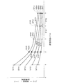
図5(b)で説明したように、流調弁65で流量調整した設定流量ごとに脈動流での吐水を図ることができる。そして、各設定流量での脈動流生成に当たり、図15で説明したように脈動波形を脈動振幅が増減するよう変更制御できる。図16および図17は、各設定流量において脈動波形を変更制御した様子を説明するための説明図、図18は、図17に示す脈動波形制御を採った場合の設定流量と刺激感との関係を説明するための説明図である。
【0079】
図16では、水勢設定ボタンで設定された洗浄水流量(設定流量レベル)ごとに、振動振幅を3段階に可変制御し、各振動振幅により刺激感を変更する。この場合は、各設定流量において振動振幅の可変幅は同じである。使用者は、水勢設定ボタンで流量を設定した後、好みに応じてソフト設定ボタン或いはハード設定ボタンを操作する。このボタン操作を受けて、局部洗浄装置10は、流調弁65で流量調整した上で給水し、波動発生ユニット70のデューティ比制御を通して図示する波形の脈動流を生成する。そして、この生成された脈動流の状態で吐水孔から洗浄水吐水を行うので、図10ないし図14で説明したように、吐水後の水塊合一を起こす。この水塊合一は脈動波形における水塊の速度分布(振動振幅)でその程度が定まることから、この合一水塊の着水による刺激感を、図示する脈動波形で定まるものに変更することができる。これにより、使用者がボタン操作で所望した刺激感を提供でき、各設定流量ごとに刺激感のソフト化・ハード化を可能とする。なお、3段階の刺激感変更としたが、図17に示すように5段階に亘る変更を行うようにすることもできる。
【0080】
図17では、設定流量レベルごとに振動振幅を多段階(5段階)に可変制御して刺激感を変更する点で、図16の場合と同様である。しかし、各設定流量における振動振幅の可変幅を、設定流量に応じて変更するようにした。使用者のボタン操作は上記した通りであり、局部洗浄装置10は、流調弁65で流量調整した上で給水し、波動発生ユニット70のデューティ比制御を通して図示する波形の脈動流を各設定流量ごとに生成する。
そして、この生成された脈動流の状態で吐水孔から洗浄水吐水を行い、上記した水塊着水による刺激感を使用者所望のものとする。
【0081】
このような刺激感付与に際し、設定流量が小さく給水洗浄水流量が少ない場合には、脈動流の振動振幅を広い範囲で変更可能とする。よって、図18に示すように、給水洗浄水流量が少ない給水状態(例えば、設定流量レベル1)においては、図10で説明した単位時間当たりの流量(脈動周期当たりの流量)が少ないにも拘わらず、脈動流吐水から得られる洗浄感(上記した水塊着水による刺激感)を大きく可変制御することができる。一方、設定流量が大きくなるほど脈動流の振動振幅の可変幅を狭くして、脈動流吐水から得られる洗浄感(上記した水塊着水による刺激感)の可変程度を少なくする。つまり、設定流量が大きく給水洗浄水流量自体が多い給水状態では、この多量の給水洗浄水流量の洗浄水が水塊状であれ局部に着水するので、たっぷりとした水量感を与えつつ、刺激感をきめ細かく可変調整できる。なお、図17の刺激感変更を、図16に示すように3段階に亘るものとすることもできる。
【0082】
図18に示すように、各設定流量ごとに5段階に刺激感を変更できることから、次のような使い方をすることもできる。
設定流量を一定としたまま、ソフト設定ボタン・ハード設定ボタンを操作すれば、その設定流量で洗浄水を給水しつつ、上記したように刺激感を大小変更する。これは、図18に記した刺激ポイントSPがSP11→SP12→SP13…、SP45→SP44→SP43…のように推移することを意味する。
【0083】
ソフト設定ボタン・ハード設定ボタンを操作することなく設定流量だけをボタン操作で変更すれば、給水洗浄水流量を変更後の設定流量に変更して洗浄水を給水しつつ、変更後の設定流量に対応した刺激感となるよう脈動流とされ当該脈動流の波形に基づく刺激感に変更する。これは、図18に記した刺激ポイントSPがSP14→SP24→SP34→SP44→SP54、SP11→SP21→SP31→SP41→SP51のように推移することを意味する。
【0084】
ソフト設定ボタン・ハード設定ボタンを操作しつつ設定流量についてもボタン操作で変更すれば、給水洗浄水流量の変更と、変更後の設定流量とソフト・ハードのボタン操作に対応した刺激感となるよう脈動流の生成とが実行され、この生成された脈動流の波形に基づく刺激感に変更する。これは、図18に記した刺激ポイントSPがSP14→SP22→SP55→SP31…のように種々推移することを意味する。よって、図18に示す刺激感がほぼ同程度の刺激ポイントがSP11→SP22→SP33→SP44→SP55のように推移するよう、設定流量と刺激感を同時に変更できる。
【0085】
次に、コイルの励磁強度、具体的には印加電圧制御の様子を設定流量ごとに異なるようにした場合について説明する。図19は、設定流量レベルが1と5である場合について印加電圧制御と洗浄水(詳しくは水塊)の移動速度・流量並びに脈動流波形を表す説明図である。
【0086】
今、時刻t0で波動発生ユニット70におけるコイル励磁のための電圧を印加したとする。この印加時刻t0における通水洗浄水は、設定流量レベル1およびレベル5の両吐水に際し、それぞれの設定流量(平均流量Qav1,Qav5)とこれに対応した流速(平均流速vav1,vav5)を持っている。この洗浄水には、印加時刻t0で印加電圧に応じた励磁強度で移動するプランジャによる脈動成分が加わる。このプランジャ移動の加速度は印加電圧に比例することから、印加電圧に大小の差がある設定流量レベル1とレベル5では、時刻t0からの速度推移が異なる。そして、各レベルの場合とも、異なる速度推移で印加オフの時刻teまで流速は増大し、時刻te後は、プランジャの戻りに応じてその流速を減じる。流量についても同じである。
【0087】
こうした脈動挙動を起こすに当たり、時刻teにおける到達流速が図示するように設定流量レベル1とレベル5で同じとなるように、各レベルでの印加電圧値(最大電圧値)を定めた。そして、それぞれの設定流量でこの最大電圧値の範囲の間の電圧でコイル励磁を行えば、各設定流量レベルにおいて、その設定流量レベルに応じた幅の振動振幅を持った脈動流を発生させることができる。この脈動流での吐水を行うので、上記したように脈動波形の振動振幅で定まる刺激感を設定流量ごと規定して、付与することができる。これにより、図17および図18を用いて説明したように、設定流量が小さく給水洗浄水流量が少ない場合には、脈動流の振動振幅を広い範囲で変更可能として刺激感を大きく変更できると共に、設定流量が大きくなるほど脈動流の振動振幅の可変幅を狭くして、刺激感の可変程度を少なくすることができる。
【0088】
なお、図19に示す電圧制御と併せて、印加オフ時刻を前後に調整するデューティ比制御を行ってもよい。
また、上記したように印加オフ時刻teにおける到達流速を各設定流量レベルで同じにしたので、図18における刺激ポイントがSP14→SP24→SP34→SP44→SP54のように推移する、流量変更・刺激感変更を行うことができる。
【0089】
上記した実施例の局部洗浄装置10では、単一の洗浄ノズル24を用いてお尻・ビデの各洗浄を行ったが、お尻用とビデ用で別々の洗浄ノズルを備えるよう変形することもできる。この変形例では、それぞれの洗浄ノズルの上流管路に波動発生ユニット70、流調切換弁75を配設すればよい。
【0090】
また、波動発生ユニット70に替えて、ラインポンプ等の加圧ポンプを備える加圧機器や断続弁を設置し、これで断続流を起こし、この断続流の洗浄水吐水を行うようにすることもできる。なお、断続の周波数は知覚限界以上の周波数である。
【0091】
次に、第2実施例について説明する。この第2実施例は、吐水孔からの洗浄水吐水時において、その吐水量に差がでる疎密現象を発現させ、この状態で着水位置まで洗浄水を飛水させる点に特徴がある。図20は、第2実施例の要部を概略的に示す説明図である。
【0092】
この第2実施例にあっても、上記の実施例と同一の水路系構成、即ち波動発生ユニット70等を有し、脈動流の状態で各吐水孔に洗浄水を通水する。そして、第2実施例の洗浄ノズル240は、各吐水孔開口部の下流直下で各ヘッド流路34〜36の管路径調整を図る構成を有する。
【0093】
図20に示すように、第2実施例の洗浄ノズル240は、ノズルヘッド242に、絞り機構201〜203を有する。これら絞り機構は、図示しない可動体とこれを駆動するための図示しないアクチュエータを備え、可動体の移動量を絞り制御装置210からの制御信号により変更する。これにより、各吐水孔から洗浄水を吐水する際の有効管路径(開口径S)を可変調整する。よって、各吐水孔からの洗浄水吐水に際しては、開口径Sの制約を受けた上で吐水される。
【0094】
この洗浄ノズル240では、図10に示したような波形の脈動流で吐水孔に通水される洗浄水に対して、次のようにして開口径Sを調整する。図21は、脈動流での通水と開口径Sの関係を説明するための説明図である。
【0095】
波動発生ユニット70により図10に示す波形(流量波形)の脈動流(周波数は知覚限界以上)で洗浄水を通水する一方、この脈動波形推移に併せて図21に示すよう波形で開口径Sを可変調整する。こうすると、脈動流流量Qが少なくこれに伴い流速Vも小さい状況では、少量の脈動流流量Qでの洗浄水の通過速度(即ち、吐水洗浄水速度v)を、開口径Sの狭小化により高くする。一方、流量Qが多く流速Vが大きい状況では、多量の脈動流流量Qでの洗浄水の吐水洗浄水速度vを、開口径Sの拡張により低くする。これにより、洗浄水水量が脈動流流量Qの大小が反映して疎密となった状況で、各吐水孔から洗浄水を吐水すると共に、吐水後の洗浄水の移動速度(吐水洗浄水速度v)は、上記した開口径調整により均一化される。しかも、水量疎密には脈動流流量Qの大小が反映している上で、この水量密状態を知覚限界以上の周波数で繰り返し起こす。そして、設定流量と所望の刺激感が上記したようにボタン操作で定まると、波動発生ユニット70で起こす脈動流の波形を図17に示すように設定流量に応じて制御し、この波形制御に併せた絞り機構201〜203による開口径調整を行う。
【0096】
これらの結果、吐水孔までは流量に繰り返し変動を来していたものの、上記の開口径調整を経て吐水孔から吐水された水塊状の洗浄水は、ほぼ同じ流速で移動(飛水)して、着水位置に着水する。そして、飛水した洗浄水水塊が洗浄箇所に着水して刺激感を呈する点で上記の実施例と変わることはない。よって、この実施例によっても、水量密時の設定流量ごとの刺激感を、設定流量が小さく給水洗浄水流量が少ない場合には、脈動流の振動振幅を広い範囲で変更可能として刺激感を大きく変更できると共に、設定流量が大きくなるほど脈動流の振動振幅の可変幅を狭くして、刺激感の可変程度を少なくすることができる。
【0097】
この第2実施例は、次のように変形することもできる。図22は、第2実施例を変形した変形例における吐水挙動を説明するための説明図である。
【0098】
この変形例では、図示するように各吐水孔へは、流量が平均流量Qavで一定かつ流速一定の連続流の状態で洗浄水を通水しつつ、上記のように開口径Sの可変調整をその調整周波数が知覚限界以上で実行する。開口径Sは、上記したように洗浄水速度に高低をもたらすと共に、通過する洗浄水量を規定することから、水量に疎密を起こす。つまり、開口径Sの狭小調整状況で吐水された洗浄水は、吐水後の移動速度vは大きくなり、開口径Sの拡張状況下その移動速度vの低下を来す。そして、図示する平均流量Qavを設定流量に応じて調整し、これと共に、各設定流量での開口径Sの広狭調整程度をその広狭幅が設定流量で異なるよう制御する。
【0099】
これらの結果、この変形例によっても、開口径調整により上記の第1実施例と同様の繰り返し変動を来した脈動波形を有する通水状態とする。よって、この変形例にあっても、上記の第1実施例と同様の効果を奏することができる。
【0100】
次に、第3実施例について説明する。この第3実施例は、吐水孔からの洗浄水吐水時において、その吐水量に差がでる疎密現象を発現させ、この状態で着水位置まで洗浄水を飛水させる点に特徴があり、この点で、第2実施例と共通する。図23は、第3実施例の要部を概略的に示す説明図、図24は、第3実施例を変形した変形例の洗浄ノズル140Aを概略的に示す説明図である。
【0101】
この第3実施例にあっても、上記の第1実施例と同一の水路系構成、即ち波動発生ユニット70等を有し、脈動流の状態で各吐水孔に洗浄水を通水する。そして、第3実施例の洗浄ノズル140は、各吐水孔開口近傍で洗浄水に空気の強制混入を図るべく、次の構成を有する。
【0102】
図23に示すように、第3実施例の洗浄ノズル140は、ノズルヘッド142に、お尻洗浄・やわらか洗浄・ビデ洗浄の各吐水孔31〜33の各ヘッド流路34〜36に連通した第1〜第3エアー流路143〜145を有する。これらエアー流路は、洗浄ノズル140の筒状部140aの上部区画室140bにおいて、エアー配管146〜148と個別に接続されている。そして、この各エアー配管には、空気ポンプ149から圧送された圧搾空気が、空気流量調整弁150での流量調節、流路切換弁150aでの流路切換を受けて、各吐水孔の開口部近傍に供給される。よって、圧搾空気は、ノズルヘッド142において、各エアー流路を介してそれぞれのヘッド流路に吹き込まれる。この場合、図24に示すように、ノズルヘッド142Aにおけるお尻洗浄・やわらか洗浄・ビデ洗浄の各ヘッド流路34〜36の各吐水孔31〜33に、それぞれ第1〜第3エアー配管151〜153を挿入することもできる。こうすれば、圧搾空気は、それぞれのヘッド流路34〜36を流れる洗浄水の中に直接噴出されるので、洗浄水流を分散させる作用を一層高めることができる。また、吐水孔近傍に、孔下流管路を環状に取り囲む多孔質の環状体を設置し、この多孔質環状体への空気混入を介して、洗浄水に空気を強制混入するようにできる。こうすれば、孔下流管路の周囲から空気を混入させるので、洗浄水分散作用をより高めることができる。
【0103】
この洗浄ノズル140では、図10に示したような波形の脈動流で吐水孔に通水される洗浄水に対して、次のようにして空気の強制混入を図る。図25は、脈動流での通水と混入空気量の関係を説明するための説明図である。
【0104】
波動発生ユニット70により図10に示す波形(流量波形)の脈動流(周波数は知覚限界以上)で洗浄水を通水する一方、空気ポンプ149からは、脈動波形推移に併せて図25に示すような混入空気量Qaで空気を強制混入する。こうすると、脈動流流量Qが少ない状況では、多量の空気が混入されるので、この混入空気のもつエネルギが洗浄水に加わる一方、流量Qが多い状況では空気量が少なくエネルギの伝達は少ない。これにより、空気混入後の洗浄水の流速(吐水洗浄水流速)vはほぼ均一化される。また、脈動流流量Qが少ない状況では、多量の空気混入により洗浄水の分散が活発なため、洗浄水が少ない水量が疎の状態となる。流量Qが多い状況では、空気量低減により洗浄水の分散は抑制され、水量が密の状態となり、この状況が脈動周期ごとに繰り返される。このように空気混入によりもたらされた水量疎密の状態を知覚限界以上の周波数で繰り返し起こして、洗浄水を疎密状態のまま交互に飛水させる。そして、洗浄水を通水させる際の脈動流の振動振幅並びに空気混入を図る際の混入空気量の振動振幅を大小調整することで、水量疎の状態での洗浄水量と水量密の状態での洗浄水量との差を調整できる。つまり、この実施例でも、上記の第2実施例と同様に、水量疎密に脈動流流量Qの大小を反映させた上で、この水量密状態を知覚限界以上の周波数で繰り返し起こし、設定流量と所望の刺激感が上記したようにボタン操作で定まると、波動発生ユニット70で起こす脈動流の波形を図17に示すように設定流量レベルに応じて広狭変更制御し、この波形制御に併せた混入空気量調整を行う。
【0105】
これらの結果、吐水孔までは流量に繰り返し変動を来していたものの、上記の空気混入を経て吐水孔から吐水された洗浄水は、ほぼ同じ流速で移動(飛水)して、着水位置に着水する。よって、この実施例では、吐水孔からの洗浄水吐水時に発現させた吐水量疎密現象を着水位置での洗浄水着水時でも起こし、洗浄水を疎密状態のまま交互に着水させる。そして、飛水した疎密状態洗浄水が洗浄箇所に着水して刺激感を呈する点で上記の実施例と変わることはない。このため、この実施例にあっても、水量密時の設定流量ごとの刺激感を、設定流量が小さく給水洗浄水流量が少ない場合には、脈動流の振動振幅を広い範囲で変更可能として刺激感を大きく変更できると共に、設定流量が大きくなるほど脈動流の振動振幅の可変幅を狭くして、刺激感の可変程度を少なくすることができる。
【0106】
この第3実施例では、次のように変形することもできる。図26は、第3実施例を更に変形した変形例における吐水挙動を説明するための説明図である。
【0107】
この変形例では、各吐水孔開口近傍で洗浄水に空気の強制混入を図るものの、図示するように各吐水孔へは、流量が平均流量Qavで一定かつ流速一定の連続流の状態で洗浄水を通水する。そして、各吐水孔には、空気ポンプ149から空気量に疎密を起こした脈動の状況(周波数は知覚限界以上)で、空気を強制混入する。こうすると、混入空気量Qaが多い状況では、この混入空気のもつエネルギが洗浄水に加わる一方、混入空気量Qaが少ない状況ではエネルギの伝達は少ない。これにより、混入空気量Qaが多い状況下で吐水された洗浄水は、吐水後の移動速度vは大きくなり、混入空気量Qaが少ない状況下の吐水洗浄水ではその移動速度は、高空気量の場合より低下する。
【0108】
これらの結果、この変形例では、流量(平均流量Qav)・流速一定で変動のない通水状態を、空気混入により上記の第1実施例と同様の繰り返し変動を来した通水状態とする。よって、この変形例にあっても、上記の第1実施例と同様の効果を奏することができる。
【0109】
特に、空気の強制混入を図る上記実施例では、吐水孔からの洗浄水(空気混入済み洗浄水)の吐出瞬間に、洗浄水中に混入済みの空気(圧縮空気)が膨張する。よって、この膨張による洗浄水流速の増速効果が高まり、流速差を顕著とするので水塊発生の高効率化、即ち刺激感の知覚向上をもたらすことができる。また、混入空気量波形の振動振幅を広狭させる空気量の脈動波形制御に加え、空気混入量(平均量)自体も増減させる制御を併用することもできる。こうすれば、低洗浄水流量領域では、平均流速自体も高めて吐水できるので効果的に刺激感を付与できる。
【0110】
上記した実施例およびその変形例では、波動発生機器74等の駆動を停止することで、従来と同様の連続流による洗浄水吐水が可能である。よって、遠隔操作装置や本体の袖部等に脈動流吐水の入り切りを選択できるボタンを設け、当該ボタンの操作に応じて、即ち、使用者の好みに応じて、各設定流量ごとで刺激感を大小調整できる局部洗浄と、平均流量で得られる一律の刺激感を各設定流量で与える局部洗浄を選択できるようにすることもできる。
【0111】
以上本発明の実施例について説明したが、本発明は上記の実施例や実施形態になんら限定されるものではなく、本発明の要旨を逸脱しない範囲において種々なる態様で実施し得ることは勿論である。
【図面の簡単な説明】
【図1】便器に装着した状態の実施例の局部洗浄装置10を表す概略斜視図である。
【図2】局部洗浄装置の概略構成を水路系を中心に表したブロック図である。
【図3】この水路系に配設されたアキュムレータ73の概略構成を示す断面図である。
【図4】同じく水路系に配設された波動発生機器74の構成を表す断面図である。
【図5】この波動発生機器74による洗浄水の流れの様子を説明する説明図である。
【図6】制御系の概略構成を表すブロック図である。
【図7】ノズル装置40を表す概略斜視図である。
【図8】洗浄ノズル24の進退の様子を説明するための説明図である。
【図9】洗浄水吐水に際して脈動を発生させる波動発生機器74の脈動発生コイル74cの励磁の様子を説明する説明図である。
【図10】波動発生機器74から流出する洗浄水の流量及び流速を示すタイミングチャートである。
【図11】ノズルヘッド25のお尻吐水孔31からの洗浄水吐水の様子を模式的に説明する説明図である。
【図12】脈動流の洗浄水を仮定の吐水孔30から吐水した場合、その吐水された洗浄水の飛水中の挙動を説明する説明図である。
【図13】着水位置TPにおける着水水量と刺激感の関係を模式的に説明する説明図である。
【図14】水塊合一の程度を説明するための説明図である。
【図15】デューティ比制御を通して、刺激感の可変の様子をお尻洗浄とビデ洗浄で異なるようにした制御例を説明する説明図である。
【図16】各設定流量において脈動波形を変更制御した様子を説明するための説明図である。
【図17】同じく、各設定流量において脈動波形を変更制御した様子を説明するための説明図である。
【図18】図17に示す脈動波形制御を採った場合の設定流量と刺激感との関係を説明するための説明図である。
【図19】設定流量レベルが1と5である場合について印加電圧制御と洗浄水(詳しくは水塊)の移動速度・流量並びに脈動流波形を表す説明図である。
【図20】第2実施例の要部を概略的に示す説明図である。
【図21】脈動流での通水と開口径Sの関係を説明するための説明図である。
【図22】第2実施例を変形した変形例における吐水挙動を説明するための説明図である。
【図23】第3実施例の要部を概略的に示す説明図である。
【図24】第3実施例を変形した変形例の洗浄ノズル140Aを概略的に示す説明図である。
【図25】脈動流での通水と混入空気量の関係を説明するための説明図である。
【図26】第3実施例を更に変形した変形例における吐水挙動を説明するための説明図である。
【符号の説明】
10…局部洗浄装置
12…本体部
14…遠隔操作装置
20…便蓋
22…袖部
24…洗浄ノズル
25…ノズルヘッド
28…表示部
29…カバー
29a…光透過窓
31…お尻吐水孔
32…やわらか吐水孔
33…ビデ吐水孔
40…ノズル装置
42…ノズル駆動モータ
43…伝達機構
44…案内レール部
45…ノズル進退軌道
50…入水側弁ユニット
60…熱交換ユニット
61…ヒータ
62…熱交換部
65…流調弁
70…波動発生ユニット
71…流路切換弁
72…下流側給水管路
74…波動発生機器
74c…電磁コイル(脈動発生コイル)
74a…シリンダ
74e…復帰スプリング
74b…プランジャ
74c…脈動発生コイル
75…流調切換弁
80…電子制御装置
140、140A…洗浄ノズル
149…空気ポンプ
150…空気流量調整弁
150a…流路切換弁
201〜203…絞り機構
210…絞り制御装置
240…洗浄ノズル
242…ノズルヘッド
BT…便器[0001]
BACKGROUND OF THE INVENTION
The present invention relates to a human body cleaning device that discharges cleaning water from a water discharge hole to a human body.
[0002]
[Prior art]
This type of human body cleaning device, for example, a local cleaning device for cleaning a human body local part, is rapidly spreading because the human body local part can be cleaned with cleaning water. In recent years, various proposals have been made for the purpose of improving the defecation inducing function and obtaining various washing feelings in order to improve the added value. For example, in the local cleaning device described in International Publication No. WO99 / 53150, cleaning water in a pulsating flow or intermittent flow state is generated by discharging the cleaning water while causing repeated fluctuations in the flow of cleaning water in a high frequency region. The water is discharged. By doing so, even if the feed water wash water flow rate (specifically, the feed water wash water flow rate per unit time) is the same, it is possible to adjust the intensity of stimulation received from the discharged water.
Alternatively, even if the feed water / wash water flow rate is reduced, it is possible to give the same level of irritation as the feed water / wash water flow rate before reduction, and the apparent wash water flow rate is increased.
[0003]
[Problems to be solved by the invention]
However, although the local cleaning device described in the above publication provides a water discharging device having a new configuration that realizes cleaning water discharging in a pulsating flow or intermittent flow, the feeling of cleaning required by the user is diverse, so The problem has been pointed out.
[0004]
The feeling of cleaning required for each local cleaning is not always uniform. For example, even the same user may have diarrhea or constipation, and the feeling of cleaning required for local cleaning differs between the former and the latter. The feeling of washing when suffering from hemorrhoids is also different. In the case of bidet cleaning, the required cleaning feeling varies depending on the degree of bleeding and the like.
[0005]
By the way, various feelings of washing are included, but depending on the case (for example, at the time of bidet washing at the time of hemorrhoids or menstruation), a large amount of washing water is supplied and discharged, and a sufficient amount of water is discharged. It may be prioritized to actually flush the wash water to the local area and wash it. In this way, when the actual amount of washing water for landing is large, the amount of water received from the landing washing water (plentiful feeling) is likely to be dominant as a bodily sensation. The need tends to be less. On the other hand, when reducing the actual washing water flow rate by reducing the feed water washing water flow rate itself, increasing the apparent washing water flow rate (landing washing water amount) by increasing the sense of stimulation with a small washing water flow rate. The necessity is high. However, in the above-mentioned conventional local cleaning device, these points are not sufficiently addressed, and there is room for further improvement.
[0006]
The present invention has been made to solve the above-described problems, and an object thereof is to diversify the feeling of cleaning according to the flow rate of the feed water and cleaning water.
[0007]
[Means for solving the problems and their functions and effects]
In order to solve at least a part of the problem, the human body cleaning device of the present invention is:
A human body cleaning device that discharges supplied cleaning water from a water discharge hole to a human body,
A flow rate setting means for setting a flow rate of cleaning water to be passed through the water discharge hole;
The supplied wash water is set by the flow rate setting means. Set flow A flow rate adjusting means for adjusting the flow rate to an amount and passing water through the water discharge hole;
Wash water passed through the water discharge hole Either flow rate or pressure Causing regular fluctuations Change that causes regular fluctuations in the flow of the washing water passed through the water discharge holes. Motion generating means;
By controlling the variation generating means, the regularity of the variation Setting flow Fluctuation control means for changing according to the amount,
The fluctuation control means is The smaller the set flow rate, the wider the variable range of the fluctuation amplitude, and the variable amplitude is changed for each set flow rate within the range of the variable width. A further amplitude changing means,
It is characterized by that.
[0008]
In the human body cleaning device of the present invention having the above-described configuration, when water supply wash water is discharged from the water discharge hole, the water supply wash water is adjusted to a set flow rate and then passed through the water discharge hole, and the flow of the water supply wash water is regulated. Cause volatile fluctuations. Then, in the state of the flow of the cleaning water in which the fluctuation has occurred, the cleaning water is discharged from the water discharge hole to make the cleaning water spouting periodic.
In addition, the regularity of fluctuations in the flow of this washing water, for example, the fluctuation period and fluctuation amplitude are changed according to the set flow rate, so that the sense of water is given by the set flow rate, and the body feels due to the regularity of fluctuation. The feeling of cleaning (for example, the feeling of stimulation) can be variously changed and controlled according to the set flow rate, resulting in diversification.
[0009]
In this case, when changing the regularity, the regularity can be changed according to the set flow rate so that the degree of change of the fluctuation regularity is different. For example, if the set flow rate is small and the feed water / wash water flow rate is small, the change variable width of the fluctuation amplitude is widened. The washing feeling that can be experienced can be greatly varied. When the set flow rate is large, the adjustment range of the cleaning feeling can be narrowed by narrowing the variable width of the fluctuation amplitude while giving a sufficient water amount feeling in the water supply state where the flow rate of the cleaning water flow is high.
[0010]
In this case, the user's feeling of cleaning received from the spout water is set (for example, setting of the intensity of stimulation), and under a situation where the set flow rate is the same, the fluctuation amplitude is increased as the setting stimulation becomes stronger. Can be.
In this way, the set feeling of stimulation can be obtained with certainty.
[0011]
By the way, like the above-described human body cleaning device of the present invention, when the flow of the cleaning water is changed and the cleaning water is discharged from the water discharge hole, the periodic cleaning water discharge becomes the following form.
The water wash water from the water discharge hole reflects the flow state of the wash water guided to the water discharge hole. If the wash water is guided to the water discharge hole in a uniform flow (continuous flow), the wash water is continuously discharged from the water discharge hole to form a continuous flow water discharge form. However, if the flow changes and the wash water is guided to the water discharge hole, a periodic water discharge form reflecting this change is obtained. In the present invention, the wash water is guided to the water discharge hole in a pulsating flow state, and the water discharge form from the water discharge hole has such a pulsation that the amount of water discharged increases or decreases reflecting this pulsating flow. When such a water discharge form is captured instantaneously, as will be described in detail later, the wash water discharged when the amount of discharged water is large becomes a water mass, and the water discharged when the water mass is small It's like being connected with water. And since the increase / decrease width of the discharged water amount reflected by the pulsating flow is none other than the fluctuation amplitude described above, the degree of water mass generation (water mass water volume) can be varied by changing the fluctuation amplitude, and the feeling of washing due to the landing of this water mass That is, the feeling of cleaning that can be experienced due to the regularity of fluctuation can be varied according to the set flow rate. For example, the intensity of the stimulation can be varied greatly when the set flow rate is small, or can be varied only small when the set flow rate is large.
[0012]
It is also possible to change the regularity of fluctuation, such as fluctuation frequency and fluctuation amplitude, regularly, irregularly, or periodically with fluctuation, and in this way, by changing the fluctuation regularity of the flow, The state of washing water discharge can be changed according to the set flow rate. Therefore, the washing feeling based on the washing water discharge in this pulsating flow changes regularly, irregularly or fluctuating periodically, so that the washing feeling is diversified at the time of washing based on the washing water supply at each set flow rate. Can be achieved.
[0013]
The following advantages can be obtained by paying attention to the intensity change of the stimulation. If the flow fluctuation regularity (for example, fluctuation frequency, fluctuation amplitude) is regularly changed, a regular change can be given to the stimulus by applying wash water spouting in the pulsating flow to the local body part. In addition, the regular change width of the stimulus can be varied according to the set flow rate. Therefore, since the massage effect by the regular intensity | strength repetition of a feeling of stimulation can be exhibited suitably at the time of washing | cleaning by each setting flow volume, defecation can be accelerated | stimulated.
On the other hand, if this stimulus changes irregularly, it is difficult to predict the state of the stimulus change, so the monotonous feeling at the time of washing can be alleviated, and the defecation promotion at the time of unintentional local washing as described later Can be achieved.
[0014]
The human body cleaning apparatus of the present invention having the above configuration can also take the following aspects. That is,
In the situation where the fluctuation generation means has the same regularity of the fluctuation of the flow, the human body does not recognize the change in the discharge state based on the wash water discharge in the state of the flow of the wash water in which the change has occurred as a stimulus change. Thus, it can have a fluctuation inducing means for inducing the fluctuation of the flow.
[0015]
By doing this, as described above, in the situation where the regularity of the fluctuation is the same, the fluctuation of the water discharge state based on the washing water discharge in the pulsating flow and the fluctuation of the flow for making the washing water discharge in this pulsating flow are the same. The human body can be prevented from recognizing as a stimulus change. For example, under a situation where the fluctuation frequency and the fluctuation amplitude are the same, it is possible to prevent the human body from recognizing that the discharge is a pulsating flow based on the fluctuation frequency or the fluctuation amplitude as a stimulus change. Therefore, the washing water is discharged in a pulsating flow, so that the water body is connected as described above, and the water is not touching the human epidermis one after another. Can cause fluctuations in the flow. For this reason, even if it is the wash water spouting by a pulsating flow, a user can be given the feeling as if receiving the wash water spouting by the continuous flow. Therefore, the washing water spouting with the pulsating flow realized in the present invention can be suitably used for normal buttocks washing and bidet washing that require continuous washing with washing water. Never give. Moreover, even if the set flow rate is different, it can be applied to such cleaning.
[0016]
In order to induce the human body not to recognize the change in the water discharge state based on the wash water discharge in the pulsating flow, the following method can be employed. When the period of washing water discharge in the pulsating flow is about 0.3 seconds, the human body is relatively clear about the stimulus change (that is, the stimulus change based on the fluctuation amplitude) caused by receiving the washing water discharge of the pulsating flow. Therefore, the fluctuation of the above-mentioned pulsating washing water discharge, that is, the fluctuation of the washing water flow to cause such water discharge should occur in a short period of about 0.2 seconds or less. Is preferred. When washing water is discharged in a pulsating flow at a frequency of about 3 Hz or less, the human body can clearly perceive the stimulus change, and if the frequency exceeds this, it cannot be perceived as a stimulus change. In other words, there is a dead zone (dead zone frequency) when perceiving a stimulus change. Therefore, in order to prevent the human body from recognizing (perceiving) the change in the water discharge state, it is preferable that the regular fluctuation of the flow of the washing water occurs at a frequency of about 5 Hz or more included in the dead band frequency. If this fluctuation occurs at the frequency of the commercial power supply, it is preferable to easily control the equipment for causing such fluctuation.
[0017]
By the way, the place where the wash water arrives (cleaning area) is, for example, an anus or a female part in local washing, but these local parts are delicate epidermis parts and are sensitive to irritation due to hemorrhoids or physiology. May be sensitive. Moreover, the degree of sensitivity is different depending on the local area. Therefore, instead of fixing the above-described dead zone region to a frequency region of about 5 Hz or more, it is possible to adjust the minimum frequency according to the local area to be cleaned. Furthermore, in the low frequency region of the dead zone, the user does not normally recognize the stimulus change during local cleaning, but the stimulus change in the wash water spout in this low frequency region due to hemorrhoid disease or physiology. Something like recognizing it can happen. Therefore, this low frequency region can be set as a boundary region of the dead zone region, and a frequency region higher than this boundary region can be set as a reliable dead zone region. In addition, in order to prevent the recognition with respect to a stimulus change reliably, it can also be performed as follows. That is, the boundary region described above is set from about 5 Hz to about 60 Hz or about 80 Hz, and a frequency region exceeding the boundary region of this frequency region is set as a reliable dead zone region.
[0018]
Since the fluctuation amplitude can be varied in accordance with the set flow rate after setting the frequency in this way, it is possible to perform cleaning without making a change in stimulation perceived in water discharge cleaning at each set flow rate.
[0019]
The fluctuation generating means for causing the fluctuation described above,
A cylinder forming a part of the water supply path;
A plunger that reciprocates in the cylinder, pulsates in the flow of cleaning water by the reciprocating motion, and pumps the cleaning water downstream of the cylinder;
An electromagnetic solenoid for reciprocating the plunger;
Excitation means for exciting the electromagnetic solenoid;
It may have a check valve that is provided in the cylinder and allows the wash water to pass downstream.
In this way, the plunger can be reciprocated in the cylinder through the excitation control of the electromagnetic solenoid, thereby causing the pulsation to flow in the washing water and pumping the washing water in a pulsating flow state.
[0020]
In addition, since a check valve is provided only on the downstream side and no check valve is provided on the upstream side of the cylinder, flush water is always guided into the cylinder regardless of the movement of the plunger when pumping in pulsating flow. Pump the wash water. Therefore, even without using a special configuration or plunger movement control, it is possible to prevent a situation where the flow rate is zero when the washing water is pumped in the pulsating flow.
[0021]
Further, the fluctuation control means is
The excitation means may be controlled to change at least one of the excitation intensity or duty ratio of the electromagnetic solenoid.
In this way, the fluctuation amplitude can be changed reliably.
[0022]
In this case, the excitation frequency can be reduced and changed as the set stimulus feeling becomes stronger or the set flow rate decreases.
[0023]
In addition, although water is discharged by causing regular fluctuations in the flow of washing water, it is sufficient to supply water at a constant feed water washing water flow rate to devices that cause fluctuations. Therefore, there are the following advantages.
[0024]
Generally, in a human body cleaning apparatus that discharges cleaning water to a local human body part, that is, a local cleaning apparatus, warmed cleaning water is discharged to alleviate discomfort when the cleaning water hits the local part. In order to achieve this warming, an instantaneous heat exchange device or a hot water storage type hot water device is installed in the channel system. When these warming devices are arranged upstream of the devices that cause fluctuations, these warming devices can be operated (heat exchange) at a constant flow rate of the feed water and washing water. Therefore, the operating conditions of the heat exchanger are constant, and the control can be simplified.
[0025]
Other aspects of the invention
The present invention may take other aspects as follows. That is,
A means for outputting a start command for washing water discharge from the water discharge hole;
The fluctuation control means may have means for receiving the start command and starting control of the fluctuation generating means.
In this way, by starting the control of the fluctuation generating means in response to the start command, a feeling of cleaning (for example, a feeling of irritation) corresponding to the set flow rate is secured while giving a sense of water volume from the beginning of water discharge. Thus, a comfortable cleaning situation can be provided to the user.
[0026]
In addition, it comprises means for discharging water from the water discharge hole in the water supply state with the water supply washing water,
The fluctuation control means includes means for selectively executing the washing water spouting in a state where regular fluctuation is caused in the flow of the water-washing water and the washing water spouting in the water supply state. It is possible to have means for periodically switching and executing both washing water discharges.
If it carries out like this, it can avoid giving a user the monotonous feeling of washing | cleaning by selection execution of two washing water discharge. Also, by selecting or switching between the two water discharge states, different cleaning feelings in each water discharge state can be given alternately, or the feeling of cleaning due to either one of the water discharge states can be used properly. Can be alleviated.
[0027]
Furthermore, having a plurality of the water discharge holes for each different water discharge target, and a water discharge unit having a pipe line leading to the water discharge hole for each water discharge hole,
Switching means for switching the supply destination of the wash water that has caused regular fluctuations by the fluctuation generating means to any of the plurality of pipes of the water discharge section may be provided.
In addition, the water discharge hole and a pipe leading to the water discharge hole, and a plurality of water discharge units prepared for different water discharge targets,
And a switching means for switching the supply destination of the cleaning water that has caused regular fluctuations by the fluctuation generating means to the pipeline of any one of the plurality of water discharging sections. it can.
[0028]
In this way, when the washing water is spouted onto different water discharge targets and washed, each water discharge target is washed with a feeling of washing (for example, a feeling of stimulation) according to the set flow rate while giving a sense of water volume by the set flow rate. can do. In this case, the frequency of fluctuation and the variable width of fluctuation amplitude can be set for each different water discharge target. For example, in consideration of the boundary area described above, various cleaning modes such as a local cleaning apparatus that change the frequency to about 71 Hz for butt cleaning, about 71 Hz for soft cleaning, and about 83 Hz for bidet cleaning are used. The frequency may be set according to the characteristics. Alternatively, the bidet cleaning can be made narrower in the variable amplitude variable width corresponding to each set flow rate than the buttocks cleaning.
[0029]
DETAILED DESCRIPTION OF THE INVENTION
Next, an embodiment in which the human body cleaning apparatus according to the present invention is applied to a local cleaning apparatus for cleaning a local body part will be described based on examples. FIG. 1 is a schematic perspective view showing a
[0030]
As shown in the figure, the
[0031]
The
[0032]
The
[0033]
The
[0034]
The upstream side
[0035]
In the upstream
[0036]
The
[0037]
The
[0038]
The
[0039]
The
[0040]
As shown in FIG. 4, the
[0041]
Since the
[0042]
In this case, the
[0043]
Further, the water pressure trajectory (linear trajectory) at the primary pressure shown in FIG. 5 (a) indicates the flow rate of the cleaning water (that is, the average water amount) when the cleaning water is allowed to flow through and spout without causing pulsation. The pulsation transition of the cleaning water pressure is reflected in the transition of the cleaning water flow rate. Therefore, if the washing water flow rate is adjusted by the
[0044]
The pulsation cycle MT seen in FIG. 5 is synchronized with the excitation cycle of the
[0045]
As shown in FIG. 6, the control system of the local cleaning apparatus of the present embodiment is mainly configured by an
[0046]
This
[0047]
Next, the
[0048]
As illustrated, the
[0049]
The
[0050]
The
[0051]
Further, the
In addition, the above-described
[0052]
Next, the manner in which the washing water is discharged from the
[0053]
When the
[0054]
The detected pressure of the pressure sensor of the pipe line can be converted into the flow rate of the cleaning water discharged from each water discharge hole of the
[0055]
As shown in FIG. 9, when the pulsation period MT shown in FIG. 5 is the period T1, and the on-time of the pulse signal is t1, the duty ratio is expressed by (t1 / T1) × 100 (%). The pressure pulsation as shown in FIG. 5 is caused by the reciprocating motion of the plunger which is turned on (driven) at this duty ratio, and this pressure fluctuation also pulsates the cleaning water flow rate. As shown in FIG. 10, the flow rate of such pulsating flow increases or decreases in the range from the maximum flow rate Qmax to the minimum flow rate Qmin, and the flow rate also increases or decreases in the range of the maximum flow rate Vmax to the minimum flow rate Vmin. In FIG. 10, the reason why the minimum flow rate Qmin and the minimum flow velocity Vmin are not zero is that the pulsation pressure by the
[0056]
In this way, the flow rate QM per pulsation cycle MT1 when water is discharged as a pulsating flow is the same as the flow rate QH in the case of a continuous flow discharged continuously at an average flow rate of the pulsating flow (see FIG. 10A).
[0057]
In this case, if the water pressure Pin introduced into the
[0058]
In addition, as described with reference to FIG. 5 (b), the washing water having a flow rate adjusted by the
[0059]
As described above, in the continuous flow continuously discharged at the average flow rate of the pulsating flow, the wash water from the water discharge hole takes the form of water discharge as shown in FIG. On the other hand, when the pulsating wash water as described above is discharged, as shown in FIG. 11B, the wash water is discharged in the form of water discharge that can be expressed discretely or in a water mass state. The And although the state of water discharge differs in both water discharge forms, the flow rate QM of the pulsating flow per pulsation cycle MT1 in the figure is equal to the flow rate QH of the continuous flow.
[0060]
Next, a description will be given of how the washing water arrives when water is discharged with a pulsating flow. FIG. 12 is an explanatory diagram for explaining the behavior of the discharged wash water in the water when the pulsating flow of wash water is discharged from the assumed
[0061]
As shown in FIG. 10A, when the washing water flow becomes a pulsating flow by the
[0062]
Now, assuming that the position indicated by TP in the figure is the landing position (that is, the human body local washing surface), the maximum flow velocity Wp3 is sequentially merged with the previous Wp2 and Wp1 to form a large water mass (Wp1 + Wp2 + Wp3), In this water mass state, water will land on the human body local cleaning surface. Following the landing of the large water mass, Wp4 and Wp5 having smaller sizes land on the water. Such water landing is repeated every coil excitation cycle (pulsation cycle MT). This phenomenon occurs due to pulsating water discharge, and the water lump due to coalescence and the above water landing state repeatedly appear at every pulsation cycle MT, and the water mass at a certain water discharge timing (Wp1 + Wp2 + Wp3) and Wp3 at the next water discharge timing. The water mass (Wp1 + Wp2 + Wp3) that has undergone the union moves and arrives at approximately the same speed (maximum speed). Then, between the water mass (Wp1 + Wp2 + Wp3) moving at the maximum speed and the water mass (Wp1 + Wp2 + Wp3), the water mass smaller in size than this water mass (that is, having a small amount of water) moves to the landing position TP. Land on the water. When the distance to the landing position TP is long, the united water mass (Wp1 + Wp2 + Wp3) may catch up with the water mass (Wp4, Wp5) in the previous pulsation cycle MT and further unite with these.
[0063]
In addition, since this maximum water arrival amount (Wp1 + Wp2 + Wp3) includes the average flow rate Wp2 and the flow rate (water amount) Wp3 exceeding the average flow rate Wp2, it becomes twice or more the average flow rate Wp2. In addition, this maximum water arrival amount (Wp1 + Wp2 + Wp3) exceeds the maximum flow rate Wp3 of the flow rate during the pulsation cycle MT.
[0064]
Also, as shown in FIG. 12 (A), immediately after water discharge, the amount of discharged water changes along the water amount trajectory of FIG. 10 (A) as Wp1->Wp2->Wp3->Wp4->Wp5-> Wp1. However, it is as follows at the landing position TP.
As described above, the water mass (Wp1 + Wp2 + Wp3) that moves at the maximum speed and the subsequent ones Wp4 and Wp5 repeatedly land at this landing position TP. Therefore, at the landing position TP, the amount of landing water changes as Wp5 → (Wp1 + Wp2 + Wp3) → Wp4 → Wp5 → (Wp1 + Wp2 + Wp3). That is, the rate of change in the amount of washing water that has landed at the landing position TP is assumed to exceed the rate of change in the amount of water immediately after water discharge at the water discharge hole, and this phenomenon is caused by the pulsation in the pulsation cycle MT. It is caused every time the water is discharged. And since the landing water mass which raise | generates such landing differs in the magnitude | size (namely, amount of water) and speed, the feeling of washing | cleaning received from the said landing at the moment of landing is different. Since this water mass landing is nothing but a collision of water with mass and speed on the human epidermis, the feeling of washing by water mass landing is experienced as a stimulus. In addition, since such a water mass landing occurs, the apparent amount of washing water for landing increases, and the feeling of water amount as a feeling of washing is also different. When the feed water cleaning water flow rate is large, not only the actual landing water cleaning amount but also the apparent landing cleaning water amount due to the water block landing is increased.
[0065]
Here, the relationship of the feeling of washing by washing water landing when performing local cleaning in the above water landing situation will be described. This feeling of washing can be explained as a feeling of water amount caused by the apparent amount of washing water for landing as an irritation feeling because it is due to the water landing on the water. Since the present invention is characterized in that the flow rate of the feed water and cleaning water (set flow rate) is associated with the feeling of irritation, the feeling of washing will be described as the feeling of irritation.
FIG. 13 is an explanatory diagram schematically illustrating the relationship between the amount of water landing and the feeling of irritation at the water landing position TP. For simplification of description, it is assumed that a water mass (Wp1 + Wp2 + Wp3) and a water mass Wp5 have repeatedly landed at the landing position TP with a pulsation cycle MT. Further, in FIG. 13, the water amount change trajectory of the pulsating flow caused by the
[0066]
As shown in the drawing, at the landing position TP, the landing of the water mass (Wp1 + Wp2 + Wp3) at the maximum water landing amount TQmax and the landing of the water mass Wp5 at the minimum water landing amount TQmin occur at each pulsation cycle MT. Therefore, in the locus point TQPmax in the figure, the feeling of stimulation is large based on the maximum landing amount TQmax at that time, and in the locus point TQPmin, the feeling of stimulation is small based on the minimum amount of landing TQmin.
[0067]
By the way, in the present embodiment, as described above, when exciting the coil, the excitation frequency is set to about 5 Hz or more (about 15 to 100 Hz) exceeding the perceptual limit frequency of the human body, and the pulsation cycle MT is set to a short time. For this reason, the interval between the trajectory point TQPmax and the trajectory point TQPmin is also short, and the expression frequency of the bodily sensation obtained at both points exceeds the perceptual limit. Therefore, the user cannot perceive that the washing water landing with the maximum water landing amount TQmax and the cleaning water landing with the minimum water landing amount TQmin are repeated. On the other hand, when the same kind of bodily sensation, i.e., the feeling of stimulation, is large or small as described above, the sensation prevailing is preferentially experienced. For this reason, the user feels only the feeling of stimulation based on the maximum water landing amount TQmax. And since the landing of the amount of washing water that gives the sense of irritation occurs beyond the perceptual limit frequency, the user perceives that the water has constantly received the maximum amount of water landing TQmax. As a result, the user can obtain a feeling of irritation based on the maximum water landing amount TQmax.
[0068]
Since the irritation is due to the above-mentioned water mass landing (that is, water mass collision), the more the water mass of the water mass generated by the coalescence of the washing water is increased. The coalescence of the washing water is caused by the difference in the water mass flow rate as described above. Therefore, if the water flow velocity difference (change rate) is increased, specifically, if the difference between the maximum flow velocity and the minimum flow velocity shown in FIG. Therefore, the feeling of irritation can be further enhanced. As described above, in this embodiment, since the instantaneous water amount changes depending on the flow velocity, it is also possible to enlarge the difference in the instantaneous water amount of the water discharged from the water discharge holes. The feeling of irritation can be increased through an increase in the amount of water.
[0069]
In order to increase the flow rate difference (movement speed difference) of the wash water, specifically the water mass, it is as follows. In this embodiment, the pulsation is caused by the reciprocating movement of the plunger, so that the flow rate of the water mass can be defined by the moving speed of the
[0070]
Here, the union degree of water mass will be described. FIG. 14 is an explanatory diagram for explaining the degree of water mass coalescence. Note that description will be made assuming that each mass point is moved (spouted) along the flow velocity trajectory shown in FIG.
[0071]
Assume that the mass point Wp1 is discharged at time t1. Since this mass point Wp1 is the flow velocity V1 (constant speed), it moves along the linear locus LV1 at that speed. Similarly, the mass points Wp2 and Wp3 also move along the respective linear trajectories LV2 and LV3. The mass point Wp3 is discharged later than the mass points Wp1 and Wp2, but moves at a speed faster than the mass points Wp1 and Wp2. Therefore, when the mass point Wp3 exceeds Δt from the discharge time t3 of the mass point Wp3, the mass point Wp3 is These mass points are caught up in the order of the mass points Wp2 and Wp1. If this mass point catch-up occurs, coalescence of the above-mentioned water mass occurs, and after coalescence, the energy of each mass point is united and the coalesced mass point moves. At this time, the energy of the mass point Wp3 is slightly lost due to coalescence, but considering that the mass (water volume) of the mass point before coalescence is different (Wp3>Wp2> Wp1), the coalescence mass point is almost the same as the mass point Wp3. Move at speed V3. On the other hand, the mass points Wp4 and Wp5 are discharged at times t4 and t5 later than the water discharge time of the mass point Wp3, and move at a speed slower than the velocity V3, respectively, so that the mass points Wp1 to Wp3 do not catch up. If the distance to the landing position is long, the mass points Wp4 and Wp5 may be caught up with the water discharge mass point following the mass points Wp4 and Wp5 during the movement to the landing position, thereby causing unification.
[0072]
As described above, if the water discharge water pressure in the vicinity of the water discharge hole is detected by the pressure sensor, the state of the water discharge washing water amount can be defined from the PQ characteristics, and the water amount of each mass point can be calculated. And the speeds V1 to V5 of the mass points can also be calculated based on the dependency with the amount of water. Therefore, not only the time until the above coalescence occurs, but also the amount of water in the coalesced water mass as a whole can be obtained.
[0073]
Further, the waveform of the pulsating flow can be changed in the following manner, thereby making it possible to vary the feeling of irritation caused by water landing. FIG. 15 is an explanatory diagram illustrating a control example in which the state of change in the feeling of stimulation is different between the buttocks cleaning and the bidet cleaning through the duty ratio control.
[0074]
As shown in FIG. 15, the duty ratio is controlled to be changed in multiple stages (three stages) in the pulsation cycles MTA and MTV during the butt cleaning and the soft / bidet cleaning. In the figure, the pulsation period is set to be large and small for both washings, and the pulsation frequencies ftm are different from each other, but they may be the same frequency. In both washings, the ratio of the three-stage duty ratio (DtmL: DtmM: DtmS) is the same, but different ratios may be used for the buttocks washing and the bidet washing.
[0075]
As indicated by the dotted line or the alternate long and short dash line in the figure, the duty ratio Dtm is changed and controlled in each cleaning. Since the duty ratio Dtm determines the coil excitation force, that is, the moving speed and moving amount of the
[0076]
In the duty ratio control for varying the feeling of stimulation as described above, the duty ratio is changed for each operation of the software setting button or the hardware setting button. For example, if the current irritation feeling is based on the duty ratio DtmM, a softer irritation feeling based on the duty ratio DtmS can be obtained by operating the software setting button once. Further, if the hardware setting button is operated, a hard stimulation feeling based on the duty ratio DtmL is obtained.
[0077]
Next, advantages obtained by the
[0078]
As described with reference to FIG. 5 (b), it is possible to discharge water in a pulsating flow for each set flow rate adjusted by the
[0079]
In FIG. 16, the vibration amplitude is variably controlled in three stages for each wash water flow rate (set flow level) set by the water force setting button, and the feeling of stimulation is changed by each vibration amplitude. In this case, the variable width of the vibration amplitude is the same at each set flow rate. After setting the flow rate with the water force setting button, the user operates the software setting button or the hardware setting button as desired. In response to this button operation, the
[0080]
FIG. 17 is the same as the case of FIG. 16 in that the vibration amplitude is variably controlled in multiple steps (five steps) for each set flow level to change the feeling of stimulation. However, the variable width of the vibration amplitude at each set flow rate is changed according to the set flow rate. The user's button operation is as described above, and the
Then, in the state of the generated pulsating flow, washing water is discharged from the water discharge hole, and the above-mentioned feeling of irritation due to the water block landing is desired by the user.
[0081]
In providing such a feeling of stimulation, when the set flow rate is small and the feed water washing water flow rate is small, the vibration amplitude of the pulsating flow can be changed in a wide range. Therefore, as shown in FIG. 18, in the water supply state where the feed water cleaning water flow rate is small (for example, the set flow level 1), the flow rate per unit time (flow rate per pulsation cycle) described in FIG. 10 is small. In addition, it is possible to largely variably control the feeling of washing obtained from the pulsating water discharge (stimulation feeling due to the above-mentioned water mass landing). On the other hand, as the set flow rate increases, the variable width of the vibration amplitude of the pulsating flow is narrowed, and the degree of change in the feeling of washing (stimulation feeling due to the above-described water mass landing) is reduced. In other words, in the water supply state where the set flow rate is large and the feed water / wash water flow rate itself is large, the wash water with this large amount of feed water / wash water flow rate will land on the local area even if it is in the form of a water mass, giving a feeling of plenty of water and a feeling of irritation. Can be variably adjusted. Note that the stimulation change shown in FIG. 17 can be performed in three stages as shown in FIG.
[0082]
As shown in FIG. 18, since the sense of stimulation can be changed in five stages for each set flow rate, the following usage is also possible.
If the software setting button / hardware setting button is operated while the set flow rate is kept constant, the stimulation feeling is changed in size as described above while supplying the cleaning water at the set flow rate. This means that the stimulation point SP shown in FIG. 18 changes as SP11 → SP12 → SP13..., SP45 → SP44 → SP43.
[0083]
If only the set flow rate is changed by operating the buttons without operating the soft setting button or hardware setting button, the changed water flow rate is changed to the new set flow rate, and the wash water is supplied to the changed set flow rate. The pulsating flow is changed to a corresponding sensation, and the sensation is based on the waveform of the pulsating flow. This means that the stimulation point SP shown in FIG. 18 changes as SP14 → SP24 → SP34 → SP44 → SP54, SP11 → SP21 → SP31 → SP41 → SP51.
[0084]
If the setting flow rate is changed by operating the software setting button / hardware setting button, the flow rate of the washing water will be changed, and the changed setting flow rate and the stimulation feeling corresponding to the software / hardware button operation will be achieved. Generation of the pulsating flow is executed, and the feeling of stimulation is changed based on the waveform of the generated pulsating flow. This means that the stimulation point SP shown in FIG. 18 makes various transitions such as SP14 → SP22 → SP55 → SP31. Therefore, the set flow rate and the feeling of stimulation can be changed at the same time so that the stimulation points having substantially the same degree of feeling shown in FIG. 18 transition as SP11 → SP22 → SP33 → SP44 → SP55.
[0085]
Next, the case where the excitation intensity of the coil, specifically, the state of applied voltage control is changed for each set flow rate will be described. FIG. 19 is an explanatory diagram showing applied voltage control, the moving speed / flow rate of washing water (specifically, water mass), and the pulsating flow waveform when the set flow level is 1 and 5.
[0086]
Now, it is assumed that a voltage for exciting the coil in the
[0087]
In causing such pulsation behavior, the applied voltage value (maximum voltage value) at each level was determined so that the flow velocity reached at time te would be the same at
[0088]
In addition to the voltage control shown in FIG. 19, duty ratio control for adjusting the application off time back and forth may be performed.
Also, as described above, since the arrival flow velocity at the application off time te is the same at each set flow rate level, the stimulation point in FIG. 18 changes as SP14 → SP24 → SP34 → SP44 → SP54. Changes can be made.
[0089]
In the
[0090]
In addition, instead of the
[0091]
Next, a second embodiment will be described. The second embodiment is characterized in that, when washing water is discharged from the water discharge hole, a density phenomenon occurs in the amount of water discharged, and the washing water is sprayed to the landing position in this state. FIG. 20 is an explanatory diagram schematically showing a main part of the second embodiment.
[0092]
Even in the second embodiment, the same water channel system configuration as that of the above-described embodiment, that is, the
[0093]
As illustrated in FIG. 20, the cleaning
[0094]
In the
[0095]
While the washing water is passed through the pulsating flow (frequency is not less than the perception limit) of the waveform (flow rate waveform) shown in FIG. 10 by the
[0096]
As a result, although the flow rate has repeatedly fluctuated up to the water discharge hole, the water-like washing water discharged from the water discharge hole after the adjustment of the opening diameter moves (flies) at almost the same flow rate. Land on the landing position. And the same as said Example by the point which the flushed water body of water splashed on the washing | cleaning location and exhibits a feeling of irritation. Therefore, also in this embodiment, when the set flow rate is small and the feed water / wash water flow rate is low, the sensation is increased by changing the vibration amplitude of the pulsating flow in a wide range. In addition to being able to change, as the set flow rate increases, the variable width of the vibration amplitude of the pulsating flow can be narrowed to reduce the variable degree of stimulation.
[0097]
The second embodiment can be modified as follows. FIG. 22 is an explanatory diagram for explaining water discharge behavior in a modified example in which the second embodiment is modified.
[0098]
In this modification, as shown in the figure, the opening diameter S is variably adjusted as described above while flowing the wash water in a continuous flow state where the flow rate is constant and the flow rate is constant at the average flow rate Qav. The adjustment frequency is executed above the perceptual limit. As described above, the opening diameter S causes the washing water speed to be high and low and regulates the amount of washing water that passes therethrough. In other words, the wash water discharged in the narrow adjustment state of the opening diameter S has a high movement speed v after the water discharge, and the movement speed v decreases under the expansion condition of the opening diameter S. Then, the illustrated average flow rate Qav is adjusted according to the set flow rate, and at the same time, the degree of adjustment of the opening diameter S at each set flow rate is controlled so that the width varies depending on the set flow rate.
[0099]
As a result, even in this modification, the water flow state having a pulsation waveform in which the same variation as in the first embodiment is caused by adjusting the opening diameter is obtained. Therefore, even in this modification, the same effect as the first embodiment can be obtained.
[0100]
Next, a third embodiment will be described. This third embodiment is characterized in that, at the time of washing water discharge from the water discharge hole, a density phenomenon that causes a difference in the amount of water discharge is expressed, and in this state the washing water is sprayed to the landing position. This is common with the second embodiment. FIG. 23 is an explanatory view schematically showing the main part of the third embodiment, and FIG. 24 is an explanatory view schematically showing a
[0101]
Even in the third embodiment, the same water channel system configuration as that in the first embodiment, that is, the
[0102]
As shown in FIG. 23, the cleaning
[0103]
In the
[0104]
As shown in FIG. 25, the oscillating
[0105]
As a result, although the flow rate has repeatedly fluctuated up to the water discharge hole, the wash water discharged from the water discharge hole through the above air mixing moves (flying water) at almost the same flow rate, and the landing position Land on the water. Therefore, in this embodiment, the water discharge amount sparseness phenomenon that occurs when the cleaning water is discharged from the water discharge holes occurs even when the cleaning water lands at the landing position, and the cleaning water is alternately landed in the sparse state. Further, the above-described embodiment is not different from the above-described embodiment in that the sparse and dense washing water that has splashed water reaches the washing portion and presents a feeling of irritation. For this reason, even in this embodiment, the stimulation sensation for each set flow rate when the amount of water is dense is set so that the vibration amplitude of the pulsating flow can be changed over a wide range when the set flow rate is small and the feed water washing water flow rate is low The feeling can be changed greatly, and the variable width of the vibration amplitude of the pulsating flow can be narrowed as the set flow rate is increased, so that the degree of stimulation feeling can be reduced.
[0106]
The third embodiment can be modified as follows. FIG. 26 is an explanatory diagram for explaining water discharge behavior in a modified example in which the third example is further modified.
[0107]
In this modification, air is forced to be mixed into the wash water in the vicinity of each water discharge hole opening. However, as shown in the figure, the water flow into the water discharge holes is a continuous flow with a constant flow rate at an average flow rate Qav and a constant flow rate. Pass water. Then, air is forcibly mixed into each water discharge hole in a pulsating state (frequency is equal to or higher than the perception limit) in which the air amount is sparse from the
[0108]
As a result, in this modified example, the water flow state where the flow rate (average flow rate Qav) and flow rate are constant and without fluctuation is changed to the water flow state where the same variation as in the first embodiment is caused by air mixing. Therefore, even in this modification, the same effect as the first embodiment can be obtained.
[0109]
In particular, in the above-described embodiment in which forced mixing of air is performed, air (compressed air) that has been mixed into the cleaning water expands at the moment when the cleaning water (cleaning water that has been mixed with air) is discharged from the water discharge hole. Therefore, the effect of increasing the washing water flow rate due to the expansion is enhanced and the difference in flow rate becomes remarkable, so that it is possible to increase the efficiency of water mass generation, that is, to improve the perception of the feeling of stimulation. Further, in addition to the air amount pulsation waveform control for widening and narrowing the vibration amplitude of the mixed air amount waveform, it is also possible to use a control for increasing or decreasing the air mixed amount (average amount) itself. In this way, in the low washing water flow rate region, the average flow velocity itself can be increased and water can be discharged, so that a sense of stimulation can be effectively provided.
[0110]
In the above-described embodiment and its modification, by stopping the driving of the
[0111]
Although the embodiments of the present invention have been described above, the present invention is not limited to the above-described embodiments and embodiments, and can of course be implemented in various modes without departing from the gist of the present invention. is there.
[Brief description of the drawings]
FIG. 1 is a schematic perspective view showing a
FIG. 2 is a block diagram showing a schematic configuration of a local cleaning device centering on a water channel system.
FIG. 3 is a cross-sectional view showing a schematic configuration of an
FIG. 4 is a cross-sectional view illustrating the configuration of a
FIG. 5 is an explanatory diagram for explaining the flow of washing water by the
FIG. 6 is a block diagram illustrating a schematic configuration of a control system.
7 is a schematic perspective view showing a
FIG. 8 is an explanatory diagram for explaining how the cleaning
FIG. 9 is an explanatory diagram for explaining a state of excitation of a
10 is a timing chart showing the flow rate and flow velocity of the wash water flowing out from the
FIG. 11 is an explanatory diagram schematically illustrating a state of cleaning water discharge from the butt
FIG. 12 is an explanatory diagram for explaining the behavior of the discharged wash water when the pulsating flow of wash water is discharged from the assumed
FIG. 13 is an explanatory diagram schematically illustrating the relationship between the amount of landing water and the feeling of irritation at the landing position TP.
FIG. 14 is an explanatory diagram for explaining the degree of water mass coalescence.
FIG. 15 is an explanatory diagram illustrating a control example in which the state of change in the feeling of stimulation is made different between buttocks cleaning and bidet cleaning through duty ratio control.
FIG. 16 is an explanatory diagram for explaining how the pulsation waveform is changed and controlled at each set flow rate.
FIG. 17 is an explanatory diagram for explaining a state in which the pulsation waveform is changed and controlled at each set flow rate.
18 is an explanatory diagram for explaining a relationship between a set flow rate and a feeling of stimulation when the pulsation waveform control shown in FIG. 17 is employed.
FIG. 19 is an explanatory diagram showing applied voltage control, the moving speed / flow rate of washing water (specifically, water mass), and the pulsating flow waveform when the set flow level is 1 and 5.
FIG. 20 is an explanatory diagram schematically showing a main part of a second embodiment.
FIG. 21 is an explanatory diagram for explaining the relationship between water flow in a pulsating flow and the opening diameter S;
FIG. 22 is an explanatory diagram for explaining water discharge behavior in a modified example obtained by modifying the second embodiment.
FIG. 23 is an explanatory diagram schematically showing a main part of a third embodiment.
FIG. 24 is an explanatory view schematically showing a
FIG. 25 is an explanatory diagram for explaining the relationship between water flow in a pulsating flow and the amount of mixed air.
FIG. 26 is an explanatory diagram for explaining water discharge behavior in a modified example in which the third embodiment is further modified.
[Explanation of symbols]
10 ... Local cleaning device
12 ... Body part
14 ... Remote control device
20 ... Toilet lid
22 ... Sleeve
24 ... Cleaning nozzle
25 ... Nozzle head
28 ... Display section
29 ... Cover
29a ... Light transmission window
31. Butt spout
32 ... Soft water spout
33 ... Bidet spout
40 ... Nozzle device
42 ... Nozzle drive motor
43. Transmission mechanism
44 ... Guide rail part
45 ... Nozzle advance / retreat trajectory
50 ... Inlet side valve unit
60 ... Heat exchange unit
61 ... Heater
62 ... Heat exchange section
65 ... Flow control valve
70: Wave generation unit
71 ... Flow path switching valve
72 ... Downstream water supply line
74: Wave generator
74c ... Electromagnetic coil (pulsation generating coil)
74a ... Cylinder
74e ... Return spring
74b ... Plunger
74c ... Pulsation generating coil
75 ... Flow control valve
80 ... Electronic control device
140, 140A ... Cleaning nozzle
149 ... Air pump
150 ... Air flow rate adjusting valve
150a ... Flow path switching valve
201-203 ... Aperture mechanism
210: Aperture control device
240 ... Cleaning nozzle
242 ... Nozzle head
BT ... toilet bowl
Claims (4)
前記吐水孔に通水される洗浄水の流量を設定する流量設定手段と、
前記給水された洗浄水を、前記流量設定手段により設定された設定流量に流量調整した上で前記吐水孔に通水する流量調整手段と、
前記吐水孔に通水される洗浄水の流速と圧力のいずれかに規則的な変動を生じさせて、前記吐水孔に通水される洗浄水の流れに規則的な変動を起こす変動発生手段と、
前記変動発生手段を制御して、前記変動の規則性を前記設定流量に応じて変更する変動制御手段とを備え、
該変動制御手段は、前記設定流量が小さいほど前記変動の振幅の可変幅を広くしつつ、該可変幅の範囲で前記変動の振幅を前記設定流量ごとに変更する振幅変更手段を有する、
ことを特徴とする人体洗浄装置。A human body cleaning device that discharges supplied cleaning water from a water discharge hole to a human body,
A flow rate setting means for setting a flow rate of cleaning water to be passed through the water discharge hole;
A flow rate adjusting means for passing water to said water discharge hole in terms of the water supply has been cleaned water, and the flow rate adjusted to set flow amount set by the flow rate setting means,
And cause regular fluctuations in either the flow rate and pressure of the washing water passed through the water discharge holes, fluctuations generating means to cause a regular variation in the flow of washing water passed through the water discharge hole When,
By controlling the variation generating means, and a variation control means for changing in accordance with regularity of the variation before Symbol set flow amount,
The variation control means, as with a wide variable range of the amplitude of the variation the set flow rate is small, an amplitude changing means to change the amplitude of the variation for each of the set flow rate range of the variable width,
A human body cleaning device characterized by that.
前記吐水孔から吐水された洗浄水から受ける使用者の洗浄感を該使用者の操作を経て設定する体感設定手段を備え、
前記振幅変更手段は、
前記設定流量が同一である状況下において、前記体感設定手段により、刺激感の強弱が前記洗浄感として設定されると、前記設定された刺激感が強くなるほど前記変動の振幅を大きくする、人体洗浄装置。A human body washing apparatus of claim 1 Symbol placement,
A sensation setting means for setting a user's feeling of washing from the washing water discharged from the water discharge hole through the user's operation,
The amplitude changing means includes
In a situation before Symbol set flow rate is the same, by the sensory setting means, when the intensity of the irritation is set as the feeling of washing, to increase the amplitude of the variation about the set irritation becomes strong, the human body Cleaning device.
前記変動発生手段は、
洗浄水の給水経路の一部をなすシリンダと、
該シリンダ内で往復動し、その往復動により洗浄水の流れに脈動を起こして洗浄水を前記シリンダ下流に圧送するプランジャと、
該プランジャを往復駆動させる電磁ソレノイドと、
該電磁ソレノイドを励磁する励磁手段と、
前記シリンダに設けられ、下流側への洗浄水の通過を許容する逆止弁とを有する、人体洗浄装置。A human body washing apparatus of placing serial to claim 1 or billed to claim 2,
The fluctuation generating means includes
A cylinder that forms part of the wash water supply path;
A plunger that reciprocates in the cylinder, pulsates in the flow of cleaning water by the reciprocating motion, and pumps the cleaning water downstream of the cylinder;
An electromagnetic solenoid for reciprocating the plunger;
Excitation means for exciting the electromagnetic solenoid;
A human body washing apparatus having a check valve provided in the cylinder and allowing passage of washing water downstream.
前記変動制御手段は、
前記励磁手段を制御して、前記電磁ソレノイドの励磁強度又はデューティ比の少なくとも一方を変更する手段を有する、人体洗浄装置。A human body washing apparatus of claim 3 Symbol mounting,
The fluctuation control means includes
A human body washing apparatus comprising means for controlling the excitation means to change at least one of excitation intensity or duty ratio of the electromagnetic solenoid.
Priority Applications (1)
| Application Number | Priority Date | Filing Date | Title |
|---|---|---|---|
| JP2000126961A JP4560884B2 (en) | 2000-04-27 | 2000-04-27 | Human body cleaning device |
Applications Claiming Priority (1)
| Application Number | Priority Date | Filing Date | Title |
|---|---|---|---|
| JP2000126961A JP4560884B2 (en) | 2000-04-27 | 2000-04-27 | Human body cleaning device |
Publications (3)
| Publication Number | Publication Date |
|---|---|
| JP2001311201A JP2001311201A (en) | 2001-11-09 |
| JP2001311201A5 JP2001311201A5 (en) | 2007-03-29 |
| JP4560884B2 true JP4560884B2 (en) | 2010-10-13 |
Family
ID=18636638
Family Applications (1)
| Application Number | Title | Priority Date | Filing Date |
|---|---|---|---|
| JP2000126961A Expired - Fee Related JP4560884B2 (en) | 2000-04-27 | 2000-04-27 | Human body cleaning device |
Country Status (1)
| Country | Link |
|---|---|
| JP (1) | JP4560884B2 (en) |
Families Citing this family (7)
| Publication number | Priority date | Publication date | Assignee | Title |
|---|---|---|---|---|
| CN102076918B (en) * | 2008-07-03 | 2012-12-26 | 松下电器产业株式会社 | Sanitary cleaning device |
| JP2010255667A (en) * | 2009-04-21 | 2010-11-11 | Inax Corp | Pulsation generating device |
| JP5633267B2 (en) * | 2009-09-30 | 2014-12-03 | Toto株式会社 | Sanitary washing device |
| EP2407602B1 (en) * | 2010-07-16 | 2020-02-12 | Toto Ltd. | Sanitary washing apparatus |
| CN102628293B (en) * | 2011-02-04 | 2015-06-17 | 松下电器产业株式会社 | Health washing device |
| CN105507399B (en) | 2014-10-14 | 2017-06-16 | Toto株式会社 | Hygienic washing device |
| JP6550767B2 (en) * | 2014-10-14 | 2019-07-31 | Toto株式会社 | Sanitary washing device |
Citations (1)
| Publication number | Priority date | Publication date | Assignee | Title |
|---|---|---|---|---|
| JP2000008453A (en) * | 1998-04-20 | 2000-01-11 | Toto Ltd | Human body washing equipment |
-
2000
- 2000-04-27 JP JP2000126961A patent/JP4560884B2/en not_active Expired - Fee Related
Patent Citations (1)
| Publication number | Priority date | Publication date | Assignee | Title |
|---|---|---|---|---|
| JP2000008453A (en) * | 1998-04-20 | 2000-01-11 | Toto Ltd | Human body washing equipment |
Also Published As
| Publication number | Publication date |
|---|---|
| JP2001311201A (en) | 2001-11-09 |
Similar Documents
| Publication | Publication Date | Title |
|---|---|---|
| JP3292185B2 (en) | Human body cleaning device | |
| WO2000043602A1 (en) | Human body washing device | |
| JP3264274B2 (en) | Human body cleaning device | |
| JP2007162463A (en) | Human body washing device | |
| US8272077B2 (en) | Sanitary washing apparatus | |
| JP2009235896A (en) | Human body washer | |
| JP6774618B2 (en) | Sanitary cleaning equipment | |
| JP4560884B2 (en) | Human body cleaning device | |
| US10190302B2 (en) | Sanitary cleansing device | |
| JP4609748B2 (en) | Human body cleaning device | |
| US10125482B2 (en) | Sanitary cleansing device | |
| JP2002356895A (en) | Bidet | |
| JP2001279777A (en) | Water discharge device | |
| JP4631174B2 (en) | Local cleaning equipment | |
| JP3882421B2 (en) | Cleaning device | |
| JP4599710B2 (en) | Local cleaning equipment | |
| JP2000282545A (en) | Human-body washing device | |
| JP2002322711A (en) | Method and device for washing private part | |
| JP3918377B2 (en) | Water discharge device | |
| JP3948173B2 (en) | Human body cleaning device | |
| JP2000240131A (en) | Actuator and human body washing device making use thereof | |
| JP2002294803A (en) | Method and device for washing the private parts | |
| JP4984267B2 (en) | Sanitary washing device | |
| JP2001090149A (en) | Human body washing device | |
| JP6826304B2 (en) | Sanitary cleaning equipment |
Legal Events
| Date | Code | Title | Description |
|---|---|---|---|
| A521 | Written amendment |
Free format text: JAPANESE INTERMEDIATE CODE: A523 Effective date: 20070207 |
|
| A621 | Written request for application examination |
Free format text: JAPANESE INTERMEDIATE CODE: A621 Effective date: 20070207 |
|
| A977 | Report on retrieval |
Free format text: JAPANESE INTERMEDIATE CODE: A971007 Effective date: 20091124 |
|
| A131 | Notification of reasons for refusal |
Free format text: JAPANESE INTERMEDIATE CODE: A131 Effective date: 20091201 |
|
| A521 | Written amendment |
Free format text: JAPANESE INTERMEDIATE CODE: A523 Effective date: 20100201 |
|
| A131 | Notification of reasons for refusal |
Free format text: JAPANESE INTERMEDIATE CODE: A131 Effective date: 20100302 |
|
| A521 | Written amendment |
Free format text: JAPANESE INTERMEDIATE CODE: A523 Effective date: 20100422 |
|
| TRDD | Decision of grant or rejection written | ||
| A01 | Written decision to grant a patent or to grant a registration (utility model) |
Free format text: JAPANESE INTERMEDIATE CODE: A01 Effective date: 20100706 |
|
| A01 | Written decision to grant a patent or to grant a registration (utility model) |
Free format text: JAPANESE INTERMEDIATE CODE: A01 |
|
| A61 | First payment of annual fees (during grant procedure) |
Free format text: JAPANESE INTERMEDIATE CODE: A61 Effective date: 20100719 |
|
| FPAY | Renewal fee payment (event date is renewal date of database) |
Free format text: PAYMENT UNTIL: 20130806 Year of fee payment: 3 |
|
| R150 | Certificate of patent or registration of utility model |
Free format text: JAPANESE INTERMEDIATE CODE: R150 |
|
| FPAY | Renewal fee payment (event date is renewal date of database) |
Free format text: PAYMENT UNTIL: 20140806 Year of fee payment: 4 |
|
| LAPS | Cancellation because of no payment of annual fees |