JP4560405B2 - Mitral valve repair device and method for use - Google Patents
Mitral valve repair device and method for use Download PDFInfo
- Publication number
- JP4560405B2 JP4560405B2 JP2004534547A JP2004534547A JP4560405B2 JP 4560405 B2 JP4560405 B2 JP 4560405B2 JP 2004534547 A JP2004534547 A JP 2004534547A JP 2004534547 A JP2004534547 A JP 2004534547A JP 4560405 B2 JP4560405 B2 JP 4560405B2
- Authority
- JP
- Japan
- Prior art keywords
- fastener
- lumen
- needle
- port
- tip
- Prior art date
- Legal status (The legal status is an assumption and is not a legal conclusion. Google has not performed a legal analysis and makes no representation as to the accuracy of the status listed.)
- Expired - Fee Related
Links
Images


Classifications
-
- A—HUMAN NECESSITIES
- A61—MEDICAL OR VETERINARY SCIENCE; HYGIENE
- A61B—DIAGNOSIS; SURGERY; IDENTIFICATION
- A61B17/00—Surgical instruments, devices or methods, e.g. tourniquets
- A61B17/04—Surgical instruments, devices or methods, e.g. tourniquets for suturing wounds; Holders or packages for needles or suture materials
- A61B17/0401—Suture anchors, buttons or pledgets, i.e. means for attaching sutures to bone, cartilage or soft tissue; Instruments for applying or removing suture anchors
-
- A—HUMAN NECESSITIES
- A61—MEDICAL OR VETERINARY SCIENCE; HYGIENE
- A61B—DIAGNOSIS; SURGERY; IDENTIFICATION
- A61B17/00—Surgical instruments, devices or methods, e.g. tourniquets
- A61B17/04—Surgical instruments, devices or methods, e.g. tourniquets for suturing wounds; Holders or packages for needles or suture materials
- A61B17/0469—Suturing instruments for use in minimally invasive surgery, e.g. endoscopic surgery
-
- A—HUMAN NECESSITIES
- A61—MEDICAL OR VETERINARY SCIENCE; HYGIENE
- A61B—DIAGNOSIS; SURGERY; IDENTIFICATION
- A61B17/00—Surgical instruments, devices or methods, e.g. tourniquets
- A61B17/04—Surgical instruments, devices or methods, e.g. tourniquets for suturing wounds; Holders or packages for needles or suture materials
- A61B17/0482—Needle or suture guides
-
- A—HUMAN NECESSITIES
- A61—MEDICAL OR VETERINARY SCIENCE; HYGIENE
- A61B—DIAGNOSIS; SURGERY; IDENTIFICATION
- A61B17/00—Surgical instruments, devices or methods, e.g. tourniquets
- A61B17/04—Surgical instruments, devices or methods, e.g. tourniquets for suturing wounds; Holders or packages for needles or suture materials
- A61B17/06—Needles ; Sutures; Needle-suture combinations; Holders or packages for needles or suture materials
- A61B17/06166—Sutures
-
- A—HUMAN NECESSITIES
- A61—MEDICAL OR VETERINARY SCIENCE; HYGIENE
- A61B—DIAGNOSIS; SURGERY; IDENTIFICATION
- A61B17/00—Surgical instruments, devices or methods, e.g. tourniquets
- A61B17/00234—Surgical instruments, devices or methods, e.g. tourniquets for minimally invasive surgery
- A61B2017/00238—Type of minimally invasive operation
- A61B2017/00243—Type of minimally invasive operation cardiac
-
- A—HUMAN NECESSITIES
- A61—MEDICAL OR VETERINARY SCIENCE; HYGIENE
- A61B—DIAGNOSIS; SURGERY; IDENTIFICATION
- A61B17/00—Surgical instruments, devices or methods, e.g. tourniquets
- A61B2017/00743—Type of operation; Specification of treatment sites
- A61B2017/00778—Operations on blood vessels
- A61B2017/00783—Valvuloplasty
-
- A—HUMAN NECESSITIES
- A61—MEDICAL OR VETERINARY SCIENCE; HYGIENE
- A61B—DIAGNOSIS; SURGERY; IDENTIFICATION
- A61B17/00—Surgical instruments, devices or methods, e.g. tourniquets
- A61B2017/00982—General structural features
- A61B2017/00991—Telescopic means
-
- A—HUMAN NECESSITIES
- A61—MEDICAL OR VETERINARY SCIENCE; HYGIENE
- A61B—DIAGNOSIS; SURGERY; IDENTIFICATION
- A61B17/00—Surgical instruments, devices or methods, e.g. tourniquets
- A61B17/04—Surgical instruments, devices or methods, e.g. tourniquets for suturing wounds; Holders or packages for needles or suture materials
- A61B17/0469—Suturing instruments for use in minimally invasive surgery, e.g. endoscopic surgery
- A61B2017/0472—Multiple-needled, e.g. double-needled, instruments
-
- A—HUMAN NECESSITIES
- A61—MEDICAL OR VETERINARY SCIENCE; HYGIENE
- A61B—DIAGNOSIS; SURGERY; IDENTIFICATION
- A61B17/00—Surgical instruments, devices or methods, e.g. tourniquets
- A61B17/30—Surgical pincettes without pivotal connections
- A61B2017/306—Surgical pincettes without pivotal connections holding by means of suction
Abstract
Description
(関連出願への相互参照)
本願は、本発明者らの同時係属中の「最小侵襲僧帽弁修復方法および装置」と題する2000年5月1日に出願された米国特許出願第09/562,406号に関する主題を開示している。前記の米国特許出願の開示は、その全体が本明細書中に参考として援用される。
(Cross-reference to related applications)
This application discloses subject matter relating to our co-pending US patent application Ser. No. 09 / 562,406, filed May 1, 2000, entitled “Minimally Invasive Mitral Valve Repair Method and Apparatus”. ing. The disclosure of the aforementioned US patent application is hereby incorporated by reference in its entirety.
(発明の背景)
脊椎動物では、心臓は、4つのポンプ輸送チャンバ:左心房、左心室、右心房および右心室を有する中空の筋肉器官である。心房は、それらの個々の心室から、個々の心房−心室接合部に位置する一方向弁によって隔離されている。これらの弁は、心臓の左側面上にある僧帽(または二尖)弁、および心臓の右側面上にある三尖弁として識別されている。左心室および右心室からの出口弁は、各々、大動脈弁および肺動脈弁として識別されている。
(Background of the Invention)
In vertebrates, the heart is a hollow muscular organ with four pumping chambers: left atrium, left ventricle, right atrium and right ventricle. The atria are isolated from their individual ventricles by one-way valves located at individual atrial-ventricular junctions. These valves have been identified as mitral (or bicuspid) valves on the left side of the heart and tricuspid valves on the right side of the heart. Outlet valves from the left and right ventricles have been identified as aortic and pulmonary valves, respectively.
これら心臓弁は、心房および心室の筋肉線維に直接的または間接的いずれかで付着する密な線維状の輪を含む弁輪中に位置決めされている。可撓性のコラーゲン構造を含む弁小葉が、輪に付着し、かつそれから内側に延び、接合エッジで出会う。大動脈弁、三尖弁および肺動脈弁は各々3つの小葉を有し、その一方、僧帽弁は2つを持つに過ぎない。通常の動作において、僧帽弁の小葉は、左心室が膨張するときに開き、それによって、血液が左心房から左心室に流れることを可能にする。次いで、小葉は、左心室の収縮サイクルの間に接合(すなわち、閉鎖)し、それによって、血液が左心房に戻ることを防ぎ、そして血液を左心室から大動脈弁を通って出るようにする。同様に、三尖弁は、右心房から右心室への流れを調節し、そして肺動脈弁は、右心室から出る血液を調節する。 These heart valves are positioned in an annulus that includes a dense fibrous annulus that attaches either directly or indirectly to atrial and ventricular muscle fibers. Valve leaflets containing a flexible collagen structure attach to the annulus and extend inward from it and meet at the joining edge. The aortic, tricuspid and pulmonary valves each have three leaflets, while the mitral valve has only two. In normal operation, the mitral leaflet opens as the left ventricle expands, thereby allowing blood to flow from the left atrium to the left ventricle. The leaflets then join (ie, close) during the left ventricular contraction cycle, thereby preventing blood from returning to the left atrium and allowing blood to exit the left ventricle through the aortic valve. Similarly, the tricuspid valve regulates flow from the right atrium to the right ventricle, and the pulmonary valve regulates blood that exits the right ventricle.
多くの臨床的理由のために、心臓弁にともなう種々の問題が発症し得る。心臓疾患の1つの共通の形態は、心臓弁の劣化または悪化を含み、これは、狭窄および/または機能不全に至る。心臓弁狭窄は、弁が適正に開かない状態である。機能不全は、弁が適正に閉じない状態である。僧帽弁の機能不全は、左心室における相対的に高い流体圧力のために最も一般的であり、血液がその意図された経路を逆行し、そして心臓収縮の間に左心室から左心房に「後方」に流れる状態である僧帽弁逆流(「MR」)を生じる。 For many clinical reasons, various problems with heart valves can develop. One common form of heart disease involves the deterioration or deterioration of the heart valve, which leads to stenosis and / or dysfunction. Heart valve stenosis is a condition in which the valve does not open properly. A malfunction is a condition in which the valve does not close properly. Mitral valve dysfunction is most common due to the relatively high fluid pressure in the left ventricle, with blood reversing its intended path and from the left ventricle to the left atrium during cardiac contraction. A mitral regurgitation ("MR") is created, which is a state of flowing "backwards".
多くの外科的技法が低下またはそうでなければ不能心臓弁を修復するために開発されている。共通の手順は、ネイティブの大動脈弁または僧帽弁を人工心臓弁で置換することを含む。このような手順は、外科医が患者の胸部を通じ(または可能には経皮的に)心臓にアクセスすることを必要とし、不能なネイティブの心臓弁および関連する組織を外科的に取り除き、周辺の弁輪を再構築し、そして再構築された輪に置換弁を固定する。これらの手順は、非常に有効であり得るが、関連する欠点もある。例えば、移植手順の高度に侵襲的な性質は、代表的には、実質的な患者の不快感を生じ、そして患者が長い回復期間の間入院することを必要とする。さらに、2つの基礎的な型の市販され入手可能な置換弁、機械的弁および組織弁は、それら自身の欠点を有している。機械的置換弁は、代表的には、長い動作寿命を提供するが、患者は、通常、彼または彼女の余命の間、抗凝固薬物の養生法を維持することが要求される。組織弁は、代表的には、身体によるより高い程度の受容性を提供し、それによって、抗凝固剤の必要性を減じるかまたはなくするが、組織弁の動作寿命は、代表的には、機械弁より短く、そしてそれ故、次の補充(単回または複数回)を必要とし得る。 Many surgical techniques have been developed to repair compromised or otherwise impossible heart valves. A common procedure involves replacing a native aortic or mitral valve with a prosthetic heart valve. Such a procedure requires the surgeon to access the heart through the patient's chest (or possibly percutaneously), surgically removing the incapable native heart valve and associated tissue, and surrounding valves. Rebuild the wheel and secure the replacement valve to the rebuilt wheel. While these procedures can be very effective, there are associated drawbacks. For example, the highly invasive nature of the implantation procedure typically results in substantial patient discomfort and requires the patient to be hospitalized for a long recovery period. In addition, two basic types of commercially available replacement valves, mechanical valves and tissue valves have their own drawbacks. Mechanical replacement valves typically provide a long operating life, but the patient is usually required to maintain an anticoagulant medication regimen for his or her life expectancy. Although tissue valves typically provide a higher degree of acceptability by the body, thereby reducing or eliminating the need for anticoagulants, the operating life of tissue valves is typically It is shorter than the mechanical valve and may therefore require the next refill (single or multiple times).
人工心臓弁補充の代替として、しばしば、ネイティブの心臓弁および/または周辺組織を再構築することが好適である。再構築手順は、しばしば、僧帽弁置換より良好な左心室機能を保持する。なぜなら、弁下乳頭筋および腱索が保存されるからである(大部分の人工弁はこれらの筋肉を利用しない)。代表的には、弁再構築は、人工輪(「弁形成リング」)を弁輪中に移植することにより達成され、輪の構造を減少および/または安定化する。弁形成リングは、代表的には、繊維縫い物材料で被覆された弾力性コアから構築される。弁形成手順は単独で実施され得るか、またはそれらは、小葉修復のような他の手順と組み合わせ実施され得る。弁形成手順は、一般的かつ良好に受容されるようになっているが、周辺輪を再形状化することおよび伝統的な小葉修復は、常に最適小葉接合に至るわけではない。結果として、特定の患者は、弁形成手順の後に、なお残存する僧帽弁逆流を経験し得る。 As an alternative to prosthetic heart valve replacement, it is often preferred to reconstruct native heart valves and / or surrounding tissue. Reconstruction procedures often retain better left ventricular function than mitral valve replacement. This is because the subvalvular papillary muscle and chordae are preserved (most prosthetic valves do not utilize these muscles). Typically, valve remodeling is accomplished by implanting a prosthetic ring (“annuloplasty ring”) into the annulus, reducing and / or stabilizing the ring structure. Annuloplasty rings are typically constructed from a resilient core that is coated with a textile sewing material. Annuloplasty procedures can be performed alone or they can be performed in combination with other procedures such as leaflet repair. Although the annuloplasty procedure has become common and well accepted, reshaping the peripheral rings and traditional leaflet repair does not always lead to optimal leaflet junctions. As a result, certain patients may experience mitral regurgitation that still remains after the annuloplasty procedure.
「弓結縛(bow−tie)」修復として知られる最近開発された技法がまた、不全心臓弁、特に僧帽弁を修復するために提唱されている。僧帽弁の弓結縛技法は、その最も単純な形態で、前方小葉および後方小葉を、それらの接合エッジの中央の近傍で一緒に縫合することを含み、それによって、血液を、2つの新たに形成された側面開口を通じて流す。これは心房から心室に流れる血液の体積をまさに減少し、この減少は、改善された小葉接合によって補償されるより多いが、これは、僧帽弁逆流を減少する。Ottavio Alfieri博士によって当初開発されたとき、このプロセスは、心臓を休止すること、および患者を体外バイパスに置くことを含み、そして小葉にアクセスおよびそれらを一緒に縫合するために侵襲的手術を必要とした。しかし、より最近、小葉が遠隔からアクセスされ、そして心臓がこの手順の間を通じて活性なままである「拍動心臓」手順が提唱されている。 A recently developed technique known as “bow-tie” repair has also been proposed to repair failing heart valves, particularly mitral valves. The mitral arch tying technique, in its simplest form, involves suturing the anterior and posterior leaflets together near the middle of their joint edges, thereby allowing the blood to Flow through the side opening formed in the. This just reduces the volume of blood flowing from the atria to the ventricles, and this reduction is more than compensated by improved lobular junctions, but this reduces mitral regurgitation. When originally developed by Dr. Ottabio Alfieri, this process involves resting the heart and placing the patient in an extracorporeal bypass and requires invasive surgery to access the leaflets and suture them together did. More recently, however, a “beating heart” procedure has been proposed in which the leaflets are accessed remotely and the heart remains active throughout this procedure.
拍動心臓弓結縛手順(すなわち、体外バイパスなし)を実施するための詳細な方法が、Columbia UniversityのMehmet Oz博士によって提案されている。この方法を実施するための方法およびデバイスは、1999年1月7日に公開されたPCT公開WO99/00059に記載されている。開示された手順の1つの実施形態では、関連するデバイスは、縫合のために接合した位置に僧帽弁小葉を握り、かつ保持するために用いられる鉗子様グラスパから構成される。僧帽弁小葉は交わり、そしてそれらの接合エッジで左心室腔中に向かってわずかに湾曲するので、このグラスパデバイスは、左心室の頂点にあるシールされたアパーチャを通過する。交わった僧帽弁小葉のエッジは、次いで、一緒に握られかつ保持され、そしてクリップまたは縫合糸のような留め具デバイスがそれらを固定するために利用される。この固定デバイスは、裂けるかまたはその他の失敗を防ぐが、これらエッジが閉じ、新たに生成された側面穴が可能な限り大きいことを確実にするに十分に組織をしっかり握って小葉組織に適用されるべきである。Mehmet OZ開示内容は、従って、このグラスパデバイスの歯が、固定の前に僧帽弁小葉の整列を可能にするように互いに関して直線状に滑動可能であり得ることを示す。この手順は、拍動心臓に対してなされるので、左心室内および僧帽弁小葉の圧力および運動は激しいことが容易に理解される。従って、Mehmet Oz博士により教示されるこの手順は、非常に技術集約的である。 A detailed method for performing a beating cardiac arch tying procedure (ie, no extracorporeal bypass) has been proposed by Dr. Mehmet Oz of Columbia University. Methods and devices for carrying out this method are described in PCT Publication WO 99/00059, published January 7, 1999. In one embodiment of the disclosed procedure, the associated device is comprised of a forceps-like glass pad that is used to grasp and hold the mitral leaflet in a joined position for suturing. Because the mitral leaflets meet and bend slightly toward the left ventricular cavity at their mating edges, the Graspa device passes through a sealed aperture at the apex of the left ventricle. The intersected mitral leaflet edges are then grasped and held together and a fastening device such as a clip or suture is utilized to secure them. This fixation device is applied to the leaflet tissue with sufficient tissue grip to prevent tearing or other failures, but ensuring that these edges are closed and the newly created side holes are as large as possible. Should be. The Mehmet OZ disclosure thus shows that the teeth of this Graspa device can be slid linearly with respect to each other to allow alignment of the mitral leaflets prior to fixation. Since this procedure is performed on a beating heart, it is readily understood that the pressure and movement of the left ventricle and mitral leaflet are intense. Thus, this procedure taught by Dr. Mehmet Oz is very technology intensive.
この弓結縛技法は、その他の不能心臓弁を処置するための実行可能な代替であることが証明されている。しかし、現在の弓結縛手順にともなういくつかの欠点が同定されている。現在のシステムは、機械的グラスパ、棘のある部材、および小葉に留め具デバイスを適用する前に弁小葉を同時に捕捉および保持する減圧デバイスを有するデバイスを含む。しばしば、これらデバイスの使用は、最適ではない小葉安定化および留め具配置を生じる。これら問題の多くは、外科医が、1つの相対的に柔軟でない手順で小葉を捕捉、保持および固定することを要求されるという事実から生じる。これらの困難性は、小葉が小さいか、または石灰化され、それらを一緒に引っ張ることを困難にするとき、および小葉が手術の間に活動的に機能している拍動心臓手順において複合される。前記を考慮して、複数の組織心臓弁小葉を安定化し、そしてそれらの間に固定デバイスを配置するための改良されたシステムに対する必要性が現在存在している。より詳細には、患者の僧帽弁を修復するための改良された弓結縛手順に対する現在の必要性が存在する。 This bow tie technique has proven to be a viable alternative for treating other inability heart valves. However, several drawbacks associated with current bow tying procedures have been identified. The current system includes a device having a mechanical grasper, a barbed member, and a vacuum device that simultaneously captures and holds the valve leaflets prior to applying the fastener device to the leaflets. Often, the use of these devices results in sub-leaflet stabilization and fastener placement. Many of these problems stem from the fact that surgeons are required to capture, hold and secure leaflets in one relatively inflexible procedure. These difficulties are compounded when the leaflets are small or calcified making it difficult to pull them together and in pulsatile heart procedures where the leaflets are actively functioning during surgery . In view of the foregoing, a need currently exists for an improved system for stabilizing a plurality of tissue heart valve leaflets and placing a fixation device therebetween. More particularly, there is a current need for an improved bowing procedure for repairing a patient's mitral valve.
(発明の簡単な要旨)
本発明の単一カテーテルの僧帽弁修復デバイスは、患者身体の全体の組織を修復するために用いられ得る。しかし、目立たない弁組織片を安定化すること、およびそれを通じて固定デバイスを展開し、それによってこれら組織片を接合することにより機能不全僧帽弁組織を修復することで特に有用である。本発明はまた、動脈中隔欠陥(ASD)、心室中隔欠陥(VSD)、および開存性卵円孔(PFO)と関連する欠陥を修復するために用いられ得る。
(Simple Summary of Invention)
The single catheter mitral valve repair device of the present invention may be used to repair the entire tissue of a patient body. However, it is particularly useful in stabilizing inconspicuous valve tissue pieces and repairing dysfunctional mitral valve tissue by deploying a fixation device therethrough and thereby joining these pieces of tissue. The present invention can also be used to repair defects associated with arterial septal defects (ASD), ventricular septal defects (VSD), and patent foramen ovale (PFO).
1つの局面では、本発明の修復デバイスは、その上に形成された少なくとも1つのポートを有する伸長可能な係合先端部、この係合先端部と連絡する少なくとも1つの展開可能な留め具、およびこのポート(単数または複数)と連絡する1つ以上のアクチュエータ部材を備える。この展開可能な留め具は、係合先端部の近位方向に位置決めされる組織を制御可能に係合かつ固定し得る。 In one aspect, a repair device of the present invention includes an extensible engagement tip having at least one port formed thereon, at least one deployable fastener in communication with the engagement tip, and One or more actuator members are in communication with the port (s). The deployable fastener can controllably engage and secure tissue positioned proximally of the engagement tip.
本発明の別の局面では、この修復デバイスは、ハンドル、細長い本体、および伸長可能な係合先端部を備える。このハンドルは、静止ハンドル本体、この静止ハンドル本体と連絡する係合先端部アクチュエータ、この静止ハンドル本体と連絡する留め具展開ハウジング、およびこの静止ハンドル本体と連絡する減圧供給源を配置し得る減圧コネクタを備える。上記細長い本体は、可撓性の本体部材、少なくとも1つの減圧管腔、1つ以上の作動管腔、および1つ以上の留め具管腔を備える。必要に応じて、この細長い本体はまた、1つ以上の補助管腔を備える。この1つ以上の作動管腔は、その中に1つ以上の作動部材を受容し得る。同様に、上記1つ以上の留め具管腔は、その中に少なくとも1つの展開可能な留め具を受容し得る。上記伸長可能な係合先端部は、上記細長い本体に取り付け得る留め具展開ハウジング、この留め具展開ハウジングに取り付けられる作動フランジ、この作動フランジに取り付けられ、かつ上記係合先端部アクチュエータと連絡する伸長可能な先端部、上記減圧コネクタと連絡する減圧ポート、および上記留め具展開ハウジングと連絡する少なくとも1つの展開可能な留め具を備える。 In another aspect of the invention, the repair device comprises a handle, an elongated body, and an extensible engagement tip. The handle includes a stationary handle body, an engagement tip actuator in communication with the stationary handle body, a fastener deployment housing in communication with the stationary handle body, and a reduced pressure connector in which a reduced pressure supply in communication with the stationary handle body can be disposed Is provided. The elongate body includes a flexible body member, at least one decompression lumen, one or more actuation lumens, and one or more fastener lumens. Optionally, the elongate body also includes one or more auxiliary lumens. The one or more actuation lumens may receive one or more actuation members therein. Similarly, the one or more fastener lumens may receive at least one deployable fastener therein. The extendable engagement tip is attachable to the elongate body, a fastener deployment housing, an actuation flange attached to the fastener deployment housing, an extension attached to the actuation flange and in communication with the engagement tip actuator A possible tip, a decompression port in communication with the decompression connector, and at least one deployable fastener in communication with the fastener deployment housing.
本発明はまた、本発明の修復デバイスを用いて組織を修復する方法を開示し、そして第1の組織部分を、減圧力で握る工程、この第1の組織部分を、機械力で安定化する工程、組織留め具を安定化された第1の組織部分に展開する工程、この第1の組織部分を脱係合する工程、少なくとも第2の組織部分を減圧力で握る工程、少なくとも第2の組織部分を機械力で安定化する工程、少なくとも第2の組織留め具を、安定化された少なくとも第2の組織部分に展開する工程、この少なくとも第2の組織部分を脱係合する工程、およびこの第1の組織部分および少なくともこの第2の組織部分を、上記第1の組織留め具および少なくとも第2の組織留め具と接合する工程を包含する。 The present invention also discloses a method of repairing tissue using the repair device of the present invention, and the step of grasping the first tissue portion with reduced pressure, stabilizing the first tissue portion with mechanical force Deploying the tissue fastener to the stabilized first tissue portion, disengaging the first tissue portion, grasping at least the second tissue portion with a reduced pressure, at least a second Stabilizing the tissue portion with mechanical force, deploying at least a second tissue fastener to the stabilized at least second tissue portion, disengaging the at least second tissue portion, and Joining the first tissue portion and at least the second tissue portion with the first tissue fastener and at least the second tissue fastener.
本発明のその他の目的、特徴、および利点は、以下の詳細な説明を考慮することから明らかになる。 Other objects, features and advantages of the present invention will become apparent from consideration of the following detailed description.
本発明の装置を、添付の図面によってより詳細に説明する。 The apparatus of the present invention will be described in more detail with reference to the accompanying drawings.
(好適な実施形態の説明)
本明細書に開示されるのは、本発明の種々の実施形態の詳細な説明である。この説明は、制限する意味で考慮されるべきではなく、本発明の一般原理を示す目的のみでなされている。この説明の全体の構成は、明瞭さのみの目的のためであり、そして本発明を制限することは意図されない。
(Description of Preferred Embodiment)
Disclosed herein is a detailed description of various embodiments of the invention. This description should not be considered in a limiting sense, but is made only for the purpose of illustrating the general principles of the invention. The overall structure of this description is for clarity purposes only and is not intended to limit the invention.
本発明の単一カテーテルの僧帽弁修復デバイスは、身体組織の外科的処置における使用のために設計されている。当業者が認識するように、本明細書に開示される例示の単一カテーテルの僧帽弁修復デバイスは、改良された組織安定化およびその上の固定デバイスの促進された配置を提供しながら、最小侵襲性の外科的手順の前、その間、およびその後に患者に対する外傷を最小にするように設計されている。本発明の単一カテーテルの僧帽弁修復デバイスは、患者身体の全体の組織を修復するために用いられ得るが、目立たない弁組織片を安定化すること、およびそれを通じて固定デバイスを展開すること、それによってこれら組織片を接合することにより機能不全僧帽弁組織を修復することで特に有用である。本発明はまた、動脈中隔欠陥(ASD)、心室中隔欠陥(VSD)、および開存性卵円孔(PFO)と関連する欠陥を修復するために用いられ得る。 The single catheter mitral valve repair device of the present invention is designed for use in body tissue surgical procedures. As those skilled in the art will appreciate, the exemplary single catheter mitral valve repair device disclosed herein provides improved tissue stabilization and facilitated placement of a fixation device thereon, while Designed to minimize trauma to the patient before, during, and after minimally invasive surgical procedures. The single catheter mitral valve repair device of the present invention can be used to repair the entire tissue of a patient body, but stabilizes inconspicuous valve tissue pieces and deploys a fixation device therethrough It is particularly useful in repairing dysfunctional mitral valve tissue by joining these pieces of tissue. The present invention can also be used to repair defects associated with arterial septal defects (ASD), ventricular septal defects (VSD), and patent foramen ovale (PFO).
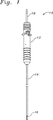
図1は、本発明の単一カテーテルの僧帽弁修復デバイスを示す。示されるように、この修復デバイス10は、細長い本体14に取り付けられたハンドル部分12を備える。係合先端部16は、この細長い本体14の遠位部分上に配置される。減圧コネクタ18は、ハンドル部分12に取り付けられる。当業者が認識するように、本発明は、制限されずに、種々の金属、プラスチック、熱可塑性物質、シリコーン、エラストマー、セラミック、合成材料、または前記材料の種々の組み合わせを含む種々の材料から製造され得る。例えば、ハンドル12はポリエチレンから製造され得、その一方、細長い本体14はエラストマーによって製造される。代替の実施形態では、この細長い本体14、係合先端部16、または両方は、放射線不透過性または音響発生材料を取り込み得、それによって、外科医が患者の身体内で修復デバイス10を正確に位置決めることを可能にする。
FIG. 1 illustrates a single catheter mitral valve repair device of the present invention. As shown, the repair device 10 includes a
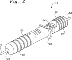
図2は、本発明のハンドル12の斜視図を示す。図2に示されるように、ハンドル12は、先端部アクチュエータ22およびそれと連絡する留め具展開アクチュエータ24を有する静止ハンドル本体20を備える。この先端部アクチュエータ22および留め具展開アクチュエータ24は、静止ハンドル本体20に対して移動可能である。例示の先端部アクチュエータ部材または留め具展開ハウジングは、例えば、ボタン、レバー、滑動可能固定物、またはトグルを含み得る。この静止ハンドル本体20の遠位部分は、その中に細長い本体14を受容し得る連結オリフィス26を含む。さらに、この静止ハンドル本体20は、その上に位置するハンドルフランジ28を含み得る。この静止ハンドル本体20、留め具展開アクチュエータ24、または先端部アクチュエータ22は、その上に配置される少なくとも1つのグリップ部材30を含み得る。図2に示されるように、減圧コネクタ18は、ハンドル12と連絡している。
FIG. 2 shows a perspective view of the
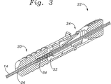
図3は、本発明のハンドル12の断面図を示す。図3に示されるように、静止ハンドル本体20は、作動チャネル32を規定し、これは、この静止ハンドル本体20の遠位部分上に形成された連結オリフィス26と連絡している。静止ハンドル本体20の内側に形成された作動チャネル32は、先端部アクチュエータ22および留め具展開アクチュエータ24を、その中に、独立かつ伸縮自在な関係で受容し得る。当業者は、本発明が、先端部アクチュエータ22または留め具展開アクチュエータ24をユーザーが独立に作動することを許容することを認識する。示されるように、付勢部材34は作動チャネル32内に位置決めされ、そして留め具展開アクチュエータ24と付勢関係で連絡し得る。この先端部アクチュエータ22は、細長い本体14中に形成された1つ以上の作動管腔(図4を参照のこと)内に位置決めされた少なくとも1つのアクチュエータ伸長部材(図7を参照のこと)と連絡している。同様に、留め具展開アクチュエータ24は、細長い本体14中に形成された1つ以上の留め具管腔(図4を参照のこと)内に位置決めされた少なくとも1つの留め具伸長部材(図6を参照のこと)と連絡している。減圧コネクタ18は、外部減圧供給源に接続されるべきであり、そして細長い本体14中に形成された減圧管腔36と流体連絡している。
FIG. 3 shows a cross-sectional view of the
本発明の細長い本体14は、ユーザーによって所望されるような、種々の長さまたは直径で製造され得る。図4Aおよび4Bは、本発明の細長い本体14の2つの実施形態の断面図を示す。図4に示されるように、本発明の細長い本体14は、少なくとも1つの減圧管腔36を備え得る。例示の実施形態では、この減圧管腔36は、デバイスの中央に配置されるけれども;当業者は、本発明が、細長い本体14内またはそれに平行して種々の位置で位置決めされる減圧管腔36を備えて容易に製造され得ることを認識する。本体部材38は、その中に形成された、1つ以上の先端部作動管腔40a、40b、1つ以上の補助管腔42、および1つ以上の留め具管腔44をさらに含み得る。例えば、図4Bは、本体部材38が、その中に、減圧管腔36、先端部作動管腔40a、40b、補助管腔42、および2つの留め具管腔44a、44bを形成する、本発明の代替の実施形態を示す。当業者は、本発明の1つ以上の補助管腔42がガイドワイヤを受容し得、それによって、本発明がガイドワイヤとともにインビボで目的の領域に向けられることを可能にすることを認識する。本発明の細長い本体14は、例えば、接着剤により取り付けられるか、またはスナップはめ関係を含む種々の様式でハンドル12に取り付けられ得る。
The
図5Aは、本発明の細長い本体14に取り付けられる係合先端部16の斜視図を示す。この係合先端部16は、留め具展開ハウジング46、伸長可能な先端部48、およびこの留め具展開ハウジング46および伸長可能な先端部48と連絡する作動フランジ50を備える。この留め具展開ハウジング46は、その上に位置決めされた組織支持54を有する少なくとも1つの減圧ポート52、およびその上に位置決めされた留め具展開ポート56をさらに含む。この組織支持54は、減圧ポート52を横切るか、または近接して配置される一連の羽板またその他の支持物を含み得る。減圧ポート52は、留め具展開ハウジング46上に配置され、細長い本体14中に形成された減圧管腔36を通ってハンドル12上に配置された減圧コネクタ18と流体連絡している。同様に、留め具展開ポート56は、細長い本体14中に形成された留め具管腔44を通じてハンドル12上に位置決めされた留め具展開アクチュエータ24と連絡している。図5Bに示される代替の実施形態では、複数の留め具展開ポート56が、留め具展開ハウジング46上に形成され得、そして細長い本体14中に形成された複数の留め具管腔44と連絡され得る(図4Bを参照のこと)。本発明の伸長可能な先端部48は、細長い本体14中に形成された作動管腔40a、40bを通ってハンドル12上に位置決めされる先端部アクチュエータ22と連絡している。この伸長可能な先端部48は、その中に展開可能なニードル64(図6を参照のこと)を受容し得る留め具受容ポート58を含み得る。この留め具受容ポート58は、留め具展開ハウジング46上に形成された留め具展開ポート56と同時整列されるか、またはそれに近接して位置決めされる。この留め具受容ポート58は、その中に展開可能なニードル64を受容し得、そして留め具材料62に取り付けられたニードルキャッチ68を含む(図6を参照のこと)。このニードルキャッチ68は、例えば、フェルール付リングまたは所定サイズのリングを含む、展開可能なニードル64をその中に、係合かつ保持し得る種々のデバイスを含み得る。さらに、上記伸長可能な先端部48は、その中に留め具材料62を受容し得る留め具チャルネル60を含み得る。好ましくは、この留め具チャネル60は、示されるように、伸長可能な先端部48の遠位端で開口している。例示の留め具材料は、例えば、糸、ワイヤ、モノフィラメント、編組みフィラメント、縫合糸材料、ニードル、縫合糸、ステープル、ボタン、組織グラスパ、組織クラスプ、棘、およびその他の組織接合デバイスを含む。
FIG. 5A shows a perspective view of the
図6は、係合先端部16の断面図を示す。減圧ポート52は、減圧管腔36と流体連絡している。展開可能なニードル64は、留め具管腔44内に配置された展開ハウジング66と連絡している。受容ポート58は、細長い本体14中に位置する補助管腔42と連絡している。展開可能なニードル64を係合かつ保持し得るニードルキャッチ68は、受容ポート58内に位置決めされ、そして係合先端部16の遠位端の周りの補助管腔42を通り、かつハンドル12に向かい戻って延びる留め具材料62に取り付けられる。
FIG. 6 shows a cross-sectional view of the
図7Aおよび7Bは、伸長された形態にあり、それによって本発明が、それに近接して位置決めされる組織を減圧力で握り、かつ安定化し得る、本発明の係合先端部16を示す。図7Aに示されるように、作動部材70a、70bは、留め具展開ハウジング46および伸長可能な先端部48中に滑動可能に受容され、それによって、伸長可能な先端部48が、留め具展開ハウジング46に対して伸縮自在関係で移動され得ることを許容する。例示の作動部材70a、70bは、例えば、ロッド、シャフト、または導管を含み得る。この作動部材70a、70bは、細長い本体14中に位置する作動管腔40a、40bを通ってハンドル12上に位置決めされる先端部アクチュエータ22と連絡している。伸長可能な先端部48を作動するために、ユーザーはこの先端部アクチュエータ22を静止ハンドル本体20に向かって進め、それによって作動部材70a、70bを進め、そして伸長可能な先端部48を留め具展開ハウジング46から延ばす結果を得る。伸長可能な先端部48を引っ込めるために、ユーザーは、先端部アクチュエータ22を静止ハンドル本体20から離して引っ込め、それによって作動部材70a、70bを引っ込め、そして伸長可能先端部48を、留め具展開ハウジング46に向かって引っ込める結果を得る。当業者は、先端部アクチュエータ22の作動が、細長い本体14の先端部アクチュエータ管腔40a、40b内に位置する作動部材70a、70bの長軸方向の動きを生じ、それによって、伸長可能な先端部48の長軸方向の伸長および退縮を生じることを認識する。図7Bは、複数(示される場合では2つ)の展開ポート56、留め具受容ポート58および対応する留め具チャネル60が存在する代替の実施形態を示す。図7Bは、留め具材料が、減圧管腔36内に(補助管腔42とは反対に、図6を参照のこと)貯蔵される別代替の実施形態を示す。
FIGS. 7A and 7B show the
図8および9は、使用の間の本発明の係合先端部16の断面図を示し、ここで、機械的安定化力が捕捉された組織に適用され得る。図8は、係合先端部16の断面図を示し、ここで、展開可能なニードル64が、留め具展開ハウジング46上に位置する留め具展開ポート56から、留め具受容ポート58を通って、そして伸長可能な先端部48中に展開されている。この展開可能なニードル64は、細長い本体14の1つ以上の留め具管腔44内に位置する展開ハウジング66に取り付けられる。この展開ハウジング66は、ハンドル12上に位置する留め具展開アクチュエータ24に連結される。この展開可能なニードル64を展開するために、ユーザーは、ハンドル12上の留め具展開アクチュエータ24を静止ハンドル本体20に向かって進め、これは、細長い本体14の留め具管腔44内の展開ハウジング66の長軸方向の動きを生じる。この展開ハウジング66の長軸方向の動きは、展開可能なニードル64が留め具展開ポート56を通り、留め具受容ポート58中に進み、そしてその中に位置するニードルキャッチ68に係合する結果を生じる。図8に示されるように、この展開可能なニードル64は、ニードルキャッチ68と係合している。このニードルキャッチ68は、補助管腔42内に位置決めされる留め具材料62に取り付けられる。
FIGS. 8 and 9 show a cross-sectional view of the
図9は、本発明の係合先端部16の断面図を示し、ここで、留め具材料62に取り付けられたニードルキャッチ68に係合し、かつそれに保持されている展開可能なニードル64は、細長い本体14の留め具管腔44内に位置している。この展開可能なニードルを引っ込めるために、ユーザーは、留め具展開アクチュエータ24を静止ハンドル本体20から離して後方に移動させる。結果として、展開ハウジング66は、後方への長軸方向運動で動き、これは、この展開ハウジング66に取り付けられている展開可能なニードル64が後方に動く結果を得る。ニードルキャッチ68および留め具材料62をそれに取り付けて有する展開可能なニードル64は、留め具受容ポート58を通って引っ込められ、そして留め具展開ポート56に入る。図9に示されるように、留め具材料62は、補助管腔42および留め具管腔44と連絡しており、それによって、作動フランジ50を横切る。本発明の代替の実施形態では、伸長可能な先端部48、留め具展開ハウジング46、または細長い本体14は、その中またはそれに取り付けられた少なくとも1つのガイドワイヤ保持デバイスまたは管腔を含み得る。なお別の実施形態では、ニードルおよびニードルキャッチの位置は逆である(すなわち、ニードルは、伸長可能な先端部48から動き、ポート56中のニードルキャッチに係合する)。
FIG. 9 shows a cross-sectional view of the
本発明はまた、インビボで目立たない組織部分を修復するために本発明の単一カテーテルの僧帽弁修復デバイスを用いる方法を開示する。以下の説明は、機能不全心臓弁を修復する方法を説明しているが、当業者は、本発明が、その他の組織修復手順における使用のために適合され得ることを認識する。 The present invention also discloses a method of using the single catheter mitral valve repair device of the present invention to repair an inconspicuous tissue portion in vivo. While the following description describes a method for repairing a dysfunctional heart valve, those skilled in the art will recognize that the present invention may be adapted for use in other tissue repair procedures.
機能不全またはそうでなければ不能心臓弁を修復するために、循環系を横切り、そして患者の心臓に侵入し得るガイドワイヤが、管内入口点を通じて患者中に導入される。例えば、管内入口点は、患者の大腿静脈または右頚静脈中に形成される。その後、ガイドワイヤがこの管内入口点を通って患者中に導入され得、そして循環系を通って進み、最終的に心臓に到着する。心臓に到着すると、ガイドワイヤは、心臓の右心房に向けられ、右心房を横切り、そして心房中隔に穿孔を作製し、それによって左心房に入る。次いで、ガイドワイヤは、心臓が弛緩期にある間に僧帽弁を通って進行され得、そして左心室を横切る。ガイドワイヤは、大動脈弁を横切って大動脈中に、そして管内出口点を通って左大腿動脈から出現するようにされる。ガイドワイヤを位置決めするこの方法論は、介入循環器科の通常の医師に公知である。一旦、ガイドワイヤが位置決めされると、管内入口点または出口ポートは拡張され、それを通るカテーテルの侵入を許容する。保護シースが、血管構造を保護するために静脈領域中に進行され得る。 In order to repair a dysfunctional or otherwise impossible heart valve, a guidewire that can traverse the circulatory system and enter the patient's heart is introduced into the patient through an intraductal entry point. For example, the intraductal entry point is formed in the patient's femoral vein or right jugular vein. A guide wire can then be introduced into the patient through this intraductal entry point and travels through the circulatory system and eventually arrives at the heart. Upon arrival at the heart, the guidewire is directed to the right atrium of the heart, traverses the right atrium, and creates a perforation in the atrial septum, thereby entering the left atrium. The guide wire can then be advanced through the mitral valve while the heart is in the relaxation phase and traverses the left ventricle. A guide wire is caused to emerge across the aortic valve into the aorta and through the intraductal exit point from the left femoral artery. This methodology for positioning the guidewire is known to the ordinary physician in the interventional cardiology department. Once the guidewire is positioned, the intraductal entry point or exit port is expanded to allow catheter entry therethrough. A protective sheath can be advanced into the venous region to protect the vasculature.
ガイドワイヤが適切に係留されると、本発明の僧帽弁修復デバイスの遠位部分が、ガイドワイヤに取り付けられ得る。その後、取り付けられた係合先端部16を有する細長い本体14が、拡張されたガイドワイヤ入口ポートを通じて僧帽弁の尖頭部分に近接する点まで進められる。当業者は、本発明の僧帽弁修復デバイス10が、ユーザーにより所望されるように、前進位置からまたは後退位置から、僧帽弁の尖頭に接近し得ることを認識する。後退アプローチのために、ユーザーは、修復デバイス10を、左大腿動脈から出現するガイドワイヤに取り付ける。次いで、デバイスを、ガイドワイヤに沿って、僧帽弁の後退面に近接する位置に進める。僧帽弁修復デバイス10の係合先端部16は、僧帽弁の組織部分72に近接して配置され得る。一旦、適切に配置されると、ハンドル12上に位置決めされた先端部アクチュエータ22が作動され得、それによって、係合先端部16の伸長可能な先端部48が、留め具展開ハウジング46から遠位方向に延びる結果を生じる。その後、外部減圧供給源(図示せず)が作動され得、減圧コネクタ18を通じて僧帽弁修復デバイス10に減圧力が付与される。外部減圧供給源(図示せず)は、細長い本体14中の少なくとも1つの減圧管腔36を通じて、係合先端部16上に位置する減圧ポート52と連絡する。伸長可能な先端部48を留め具展開ハウジング46から延ばして、減圧ポート52に近接して位置決めされる組織部分72は、この外部減圧供給源(図示せず)によって付与される減圧力によって握られ、かつ保持される。一旦、この組織部分72が、減圧ポート52を通じて提供される減圧力によって捕捉されると、ハンドル12上に位置する先端部アクチュエータ22が作動されて伸長可能な先端部48を留め具展開ハウジング46に向かって引っ込め、それによってその間に組織部分72を機械的に保持かつ安定化する。一旦、組織が十分に安定化されると、ハンドル12上に位置する留め具展開アクチュエータ24は作動され得、組織部分72を通じて留め具デバイスを展開する。留め具デバイスを展開するために、ユーザーは、留め具展開アクチュエータ24をハンドル12の静止ハンドル本体20上に位置決めされるハンドルフランジ28に向かって進め、それによって、展開可能なニードル64を展開ポート56から出し、そして作動フランジ50内に配置される組織を横切らせる。その後、この展開可能なニードル64は、伸長可能な先端部48上に形成された受容ポート58中に入り、そして留め具チャネル60内に位置決めされた留め具材料62に取り付けられているニードルキャッチ68に係合する。この留め具展開ハウジング46は、ユーザーによって非展開位置に戻され、それによって、留め具材料60に取り付けられたニードルキャッチ68を保持した展開可能ニードル64が、細長い本体14の留め具管腔44内に非展開位置に戻る結果を生じ、そして、留め具材料62を有する組織部分72がそれによって位置決めされる結果を生じる。図10に示されるように、留め具材料62が組織部分72を通じて位置決めされ、外部減圧供給源は停止され得、これは、捕捉された組織部分72の解放を生じる。その後、本発明の僧帽弁修復デバイス10は、患者の身体から除去され、組織部分72に取り付けられた留め具材料62を残す。
When the guidewire is properly anchored, the distal portion of the mitral valve repair device of the present invention can be attached to the guidewire. Thereafter, the
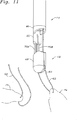
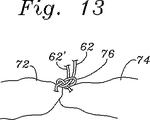
一旦、患者の身体から除去されると、僧帽弁修復デバイス10は、展開可能なニードルおよび止め具材料が再装填され得、回転され得、そして患者中に再導入され、それによって、このデバイスが、その既に固定された組織に隣接する身体の組織にさらなる組織止め具を付与することを可能にする。本発明の僧帽弁修復デバイスの少なくとも遠位部分は、ガイドワイヤに再び取り付けられる。その後、取り付けられた係合先端部16を有する細長い本体14は、拡張されたガイドワイヤ入口ポートを通り、僧帽弁の尖頭部分に近接する点まで再び進められる。僧帽弁修復デバイス10の係合先端部16は、僧帽弁の別の組織部分74に近接して位置決めされ得る。次いで、先行のプロセスが繰り返され、縫合糸材料62’を組織部分74に固定する。図11は、第1の組織部分72の近傍に位置する第2の組織部分74に近接して位置決めされた僧帽弁修復デバイス10を示す。示されるように、留め具材料62’は、組織部分74を通って位置決めされ、そして外部減圧供給源が停止され得、これは、捕捉された組織部分74の解放を生じる。その後、本発明の僧帽弁修復デバイス10は、患者の身体から除去され得、そして組織部分74に取り付けられた留め具材料62’を残して患者の身体から除去され得る。その後、留め具材料の部分62、62’が連結されて、個々の組織部分72、74を接合する。図12〜13に示されるように、結び目76が留め具材料62,62’中に形成され、そして組織部分72、74に進められる。1つの実施形態では、この結び目76は、患者の身体の外部で形成され、そして結び目押し出しデバイスで修復部位まで進められる。
Once removed from the patient's body, the mitral valve repair device 10 can be reloaded with a deployable needle and stop material, rotated, and reintroduced into the patient, whereby the device Makes it possible to apply further tissue stops to the body tissue adjacent to the already fixed tissue. At least the distal portion of the mitral valve repair device of the present invention is reattached to the guide wire. The
図4B、5Bおよび7Bの代替の実施形態では、この修復デバイスは、第1および第2の組織片を固定する工程の間で患者から除去される必要はない。これらの代替の実施形態の二重固定システムは、留め具材料が、組織の第1の片を固定した後、デバイスを単に回転することにより、組織の両方の片の中に連続的に配置されることを可能にする。最後に、当業者は、減圧供給源が十分に強力で、そしてニードル64が十分に鋭い場合、伸長可能な先端部64は組織をその場に機械的に保持するために展開ハウジング46に対して動かす必要はないことを理解する。組織片は、減圧された場所で一緒に保持され得、機械的保持を使用することなく、穿孔される。
In the alternative embodiment of FIGS. 4B, 5B and 7B, the repair device need not be removed from the patient during the process of fixing the first and second tissue pieces. The dual fixation system of these alternative embodiments is such that the fastener material is continuously placed in both pieces of tissue by simply rotating the device after fixing the first piece of tissue. Make it possible. Finally, those skilled in the art will recognize that if the reduced pressure source is sufficiently powerful and the
終わりに、本明細書中に開示される本発明の実施形態は、本発明の原理の例示であることが理解される。本発明の範囲内にあるその他の改変が採用され得る。従って、本発明は、正確に本開示で示されそして説明されるものに制限されない。 Finally, it is understood that the embodiments of the invention disclosed herein are illustrative of the principles of the present invention. Other modifications within the scope of the present invention may be employed. Accordingly, the present invention is not limited to that precisely as shown and described in this disclosure.
Claims (8)
近位端および遠位端を有する細長い本体であって、該本体内に形成された少なくとも1つの管腔を有する、細長い本体;
該細長い本体の遠位端にある留め具展開ハウジングであって、その上に少なくとも1つの留め具展開ポートを有する、留め具展開ハウジング;
該留め具展開ハウジングに対し、伸縮自在な関係で移動することが可能な伸長可能な係合先端部であって、該伸張可能な係合先端部は、その上に形成された少なくとも1つの留め具受容ポートを有し、該伸張可能な係合先端部は、該留め具展開ハウジングから遠位方向に延びるように構成され、該伸張可能な係合先端部は、該留め具展開ハウジングに向かって近位方向に引っ込められ、それによって該伸張可能な係合先端部と該留め具展開ハウジングとの間に組織セグメントを機械的に保持かつ安定化するように構成されている、伸長可能な係合先端部;
先端部アクチュエータであって、該伸張可能な先端部を、該留め具展開ハウジングから遠位方向に延びるようにし、その後、該伸張可能な先端部を、該留め具展開ハウジングに向かって引っ込められるようにし、それによって該伸張可能な係合先端部と該留め具展開ハウジングとの間に該組織セグメントを機械的に保持かつ安定化するように構成されている、先端部アクチュエータ;
少なくとも1つの展開可能な留め具であって、該展開可能な留め具は、該組織セグメントが、該伸張可能な係合先端部と該留め具展開ハウジングとの間で機械的に保持され安定化されるときに、該組織セグメントを係合することが可能である、少なくとも1つの展開可能な留め具;および
該展開可能な留め具と連絡し、かつ該留め具を該組織セグメントに係合させることが可能な少なくとも1つの留め具展開アクチュエータであって、該少なくとも1つの留め具展開アクチュエータは、該先端部アクチュエータから独立して活動させられるように構成されている、少なくとも1つの留め具展開アクチュエータ、
を備え、
該展開可能な留め具は、第1の縫合糸部分の形態の留め具材料を備え、該装置は、
該細長い本体に形成された第1の留め具管腔であって、該第1の留め具管腔の内部に位置決めされた第1のニードルを有する、第1の留め具管腔;
該細長い本体に位置決めされた第1の留め具展開ポートであって、該第1の留め具展開ポートは、該第1の留め具管腔と連絡している、第1の留め具展開ポート;
第1の留め具受容ポートであって、該第1の留め具展開ポートと整列しており、かつ該第1の留め具展開ポートと対向している、第1の留め具受容ポート;および
該第1のニードルに取り付けられた第1のアクチュエータであって、該第1のアクチュエータは、該第1の留め具展開ポートを介して該第1の留め具管腔から該第1のニードルを進め、該第1の留め具受容ポートに入れるように活動させられるように構成されている、第1のアクチュエータ、
をさらに備え、
該第1のニードルは、該留め具材料に固定され、該第1のニードルは、その後、それに取り付けられた該留め具材料と共に、該留め具受容ポートおよび該留め具展開ポートを通って引っ込められるように構成されている、装置。A device for securing tissue within a patient's body, comprising:
An elongate body having a proximal end and a distal end, the elongate body having at least one lumen formed therein;
A fastener deployment housing at a distal end of the elongate body having at least one fastener deployment port thereon;
An extensible engagement tip that is movable relative to the fastener deployment housing, wherein the extensible engagement tip is formed on at least one fastener formed thereon. Having an instrument receiving port, the extensible engagement tip configured to extend distally from the fastener deployment housing, the extensible engagement tip facing the fastener deployment housing. A retractable engagement member configured to mechanically retain and stabilize a tissue segment between the retractable engagement tip and the fastener deployment housing. Joint tip;
A tip actuator, such that the extensible tip extends distally from the fastener deployment housing so that the extensible tip can be retracted toward the fastener deployment housing. A tip actuator configured to mechanically hold and stabilize the tissue segment between the extensible engagement tip and the fastener deployment housing;
At least one deployable fastener, wherein the deployable fastener has the tissue segment mechanically retained and stabilized between the extensible engagement tip and the fastener deployment housing. At least one deployable fastener that is capable of engaging the tissue segment when done; and in communication with the deployable fastener and engaging the fastener with the tissue segment At least one fastener deployment actuator, wherein the at least one fastener deployment actuator is configured to be activated independently of the tip actuator ,
Equipped with a,
The deployable fastener comprises a fastener material in the form of a first suture portion, the device comprising:
A first fastener lumen formed in the elongate body, the first fastener lumen having a first needle positioned within the first fastener lumen;
A first fastener deployment port positioned in the elongate body, wherein the first fastener deployment port is in communication with the first fastener lumen;
A first fastener receiving port, wherein the first fastener receiving port is aligned with and is opposite to the first fastener deployment port; and
A first actuator attached to the first needle, the first actuator disengaging the first needle from the first fastener lumen via the first fastener deployment port; A first actuator configured to be advanced and activated to enter the first fastener receiving port;
Further comprising
The first needle is secured to the fastener material, and the first needle is then retracted through the fastener receiving port and the fastener deployment port with the fastener material attached thereto. The device is configured as follows .
前記細長い本体に形成された第2のニードル管腔であって、該第2のニードル管腔の内部に位置決めされた第2のニードルを有する、第2のニードル管腔;
該細長い本体において位置決めされた第2のニードルポートであって、該第2のニードル管腔と連絡している、第2のニードルポート;
該細長い本体の内部に形成された、第2の縫合糸管腔であって、該第2の縫合糸管腔は、その内部に第2の縫合糸部分を有する、第2の縫合糸管腔;
該第2の縫合糸管腔と連絡する第2の留め具受容ポートであって、該第2のニードルポートと整列しており、かつ該第2のニードルポートと対向している、第2の留め具受容ポート;および
該第2のニードルに取り付けられた第2のアクチュエータであって、該第2のアクチュエータは、該第2のニードル管腔から該第2のニードルを進め、該第2の留め具受容ポートに入れるように活動させられるように構成されており、前記第1のアクチュエータとは独立して作動可能である、第2のアクチュエータ、
をさらに備える、請求項1に記載の装置。The at least one lumen includes a first suture lumen having the first suture portion therein, and the first fastener receiving port communicates with the first suture lumen. And said device is:
A second needle lumen formed in the elongate body, the second needle lumen having a second needle positioned within the second needle lumen;
A second needle port positioned in the elongate body and in communication with the second needle lumen;
Said sub formed within the elongate body, and a second suture lumen, the suture lumen of the second has a second suture portion therein, the second suture lumen ;
A second fastener receiving port in communication with the second suture lumen, wherein the second fastener receiving port is aligned with the second needle port and is opposite the second needle port; A fastener receiving port; and a second actuator attached to the second needle, the second actuator advancing the second needle from the second needle lumen, A second actuator configured to be activated to enter the fastener receiving port and operable independently of the first actuator;
Further comprising an apparatus according to claim 1.
をさらに備え、
前記第1のニードルは、前記第1のニードルキャッチを保持するために、前記第1の留め具管腔から進められ、前記第1の留め具受容ポートに入れられ、その後、該保持された第1のニードルキャッチを該第1の留め具管腔に引き寄せるために、該第1の留め具管腔に引っ込められるように構成されている、請求項1に記載の装置。A first needle catch secured to the first suture portion and positioned in the first fastener receiving port;
Further comprising
The first needle is advanced from the first fastener lumen and placed into the first fastener receiving port to retain the first needle catch and then the retained first The device of claim 1 , wherein the device is configured to be retracted into the first fastener lumen to draw a needle catch into the first fastener lumen.
前記第2の縫合糸部分に固定され、前記第2の留め具受容ポートに位置決めされた第2のニードルキャッチ、
をさらに備え、
前記第1のニードルは、前記第1のニードルキャッチを保持するために、前記第1の留め具管腔から進められ、前記第1の留め具受容ポートに入れられ、その後、該保持された第1のニードルキャッチを該第1の留め具管腔に引き寄せるために、該第1の留め具管腔に引っ込められるように構成されており、
前記第2のニードルは、前記第2のニードルキャッチを保持するために、前記第2の留め具管腔から進められ、前記第2の留め具受容ポートに入れられ、その後、該保持された第2のニードルキャッチを該第2の留め具管腔に引き寄せるために、該第2の留め具管腔に引っ込められるように構成されている、請求項2に記載の装置。A first needle catch fixed to the first suture portion and positioned in the first fastener receiving port; and fixed to the second suture portion and attached to the second fastener receiving port. A second needle catch positioned,
Further comprising
The first needle is advanced from the first fastener lumen and placed into the first fastener receiving port to retain the first needle catch and then the retained first Is configured to be retracted into the first fastener lumen to draw a needle catch into the first fastener lumen;
The second needle is advanced from the second fastener lumen to enter the second fastener receiving port to retain the second needle catch, and then the retained second needle. The device of claim 2 , wherein the device is configured to be retracted into the second fastener lumen to draw two needle catches into the second fastener lumen.
前記留め具展開ハウジングに位置決めされた少なくとも1つの減圧ポートであって、該少なくとも1つの減圧ポートは、該減圧管腔と連絡し、該少なくとも1つの減圧ポートは、該減圧管腔を介して該少なくとも1つの減圧ポートに付与された減圧力を用いて組織セグメントを捕捉するように構成されている、減圧ポート、
をさらに備える、請求項1に記載の装置。The at least one lumen is a decompression lumen;
At least one decompression port positioned in the fastener deployment housing, wherein the at least one decompression port communicates with the decompression lumen, the at least one decompression port via the decompression lumen; A decompression port configured to capture a tissue segment using a decompression force applied to at least one decompression port;
The apparatus of claim 1, further comprising:
Applications Claiming Priority (2)
| Application Number | Priority Date | Filing Date | Title |
|---|---|---|---|
| US10/233,879 US7083628B2 (en) | 2002-09-03 | 2002-09-03 | Single catheter mitral valve repair device and method for use |
| PCT/US2003/027661 WO2004021893A1 (en) | 2002-09-03 | 2003-09-02 | Mitral valve repair device and method for use |
Publications (3)
| Publication Number | Publication Date |
|---|---|
| JP2005537110A JP2005537110A (en) | 2005-12-08 |
| JP2005537110A5 JP2005537110A5 (en) | 2006-10-26 |
| JP4560405B2 true JP4560405B2 (en) | 2010-10-13 |
Family
ID=31977314
Family Applications (1)
| Application Number | Title | Priority Date | Filing Date |
|---|---|---|---|
| JP2004534547A Expired - Fee Related JP4560405B2 (en) | 2002-09-03 | 2003-09-02 | Mitral valve repair device and method for use |
Country Status (6)
| Country | Link |
|---|---|
| US (6) | US7083628B2 (en) |
| EP (1) | EP1542597A1 (en) |
| JP (1) | JP4560405B2 (en) |
| AU (2) | AU2003265916B2 (en) |
| CA (1) | CA2495465A1 (en) |
| WO (1) | WO2004021893A1 (en) |
Families Citing this family (272)
| Publication number | Priority date | Publication date | Assignee | Title |
|---|---|---|---|---|
| US6050936A (en) | 1997-01-02 | 2000-04-18 | Myocor, Inc. | Heart wall tension reduction apparatus |
| FR2768324B1 (en) | 1997-09-12 | 1999-12-10 | Jacques Seguin | SURGICAL INSTRUMENT FOR PERCUTANEOUSLY FIXING TWO AREAS OF SOFT TISSUE, NORMALLY MUTUALLY REMOTE, TO ONE ANOTHER |
| US6332893B1 (en) * | 1997-12-17 | 2001-12-25 | Myocor, Inc. | Valve to myocardium tension members device and method |
| US6260552B1 (en) * | 1998-07-29 | 2001-07-17 | Myocor, Inc. | Transventricular implant tools and devices |
| US20040044350A1 (en) | 1999-04-09 | 2004-03-04 | Evalve, Inc. | Steerable access sheath and methods of use |
| US8216256B2 (en) * | 1999-04-09 | 2012-07-10 | Evalve, Inc. | Detachment mechanism for implantable fixation devices |
| US7811296B2 (en) | 1999-04-09 | 2010-10-12 | Evalve, Inc. | Fixation devices for variation in engagement of tissue |
| US6752813B2 (en) | 1999-04-09 | 2004-06-22 | Evalve, Inc. | Methods and devices for capturing and fixing leaflets in valve repair |
| WO2000060995A2 (en) * | 1999-04-09 | 2000-10-19 | Evalve, Inc. | Methods and apparatus for cardiac valve repair |
| US7666204B2 (en) * | 1999-04-09 | 2010-02-23 | Evalve, Inc. | Multi-catheter steerable guiding system and methods of use |
| ATE329531T1 (en) | 1999-07-02 | 2006-07-15 | Quickpass Inc | SURGICAL SEWING DEVICE |
| US7083628B2 (en) | 2002-09-03 | 2006-08-01 | Edwards Lifesciences Corporation | Single catheter mitral valve repair device and method for use |
| US7220266B2 (en) | 2000-05-19 | 2007-05-22 | C. R. Bard, Inc. | Tissue capturing and suturing device and method |
| SE0002878D0 (en) * | 2000-08-11 | 2000-08-11 | Kimblad Ola | Device and method of treatment of atrioventricular regurgitation |
| US6723038B1 (en) * | 2000-10-06 | 2004-04-20 | Myocor, Inc. | Methods and devices for improving mitral valve function |
| US6602286B1 (en) * | 2000-10-26 | 2003-08-05 | Ernst Peter Strecker | Implantable valve system |
| US6702835B2 (en) | 2001-09-07 | 2004-03-09 | Core Medical, Inc. | Needle apparatus for closing septal defects and methods for using such apparatus |
| US20060052821A1 (en) | 2001-09-06 | 2006-03-09 | Ovalis, Inc. | Systems and methods for treating septal defects |
| US6776784B2 (en) | 2001-09-06 | 2004-08-17 | Core Medical, Inc. | Clip apparatus for closing septal defects and methods of use |
| US6764510B2 (en) | 2002-01-09 | 2004-07-20 | Myocor, Inc. | Devices and methods for heart valve treatment |
| US7048754B2 (en) * | 2002-03-01 | 2006-05-23 | Evalve, Inc. | Suture fasteners and methods of use |
| US6752828B2 (en) * | 2002-04-03 | 2004-06-22 | Scimed Life Systems, Inc. | Artificial valve |
| US7007698B2 (en) * | 2002-04-03 | 2006-03-07 | Boston Scientific Corporation | Body lumen closure |
| AU2003245507A1 (en) * | 2002-06-13 | 2003-12-31 | Guided Delivery Systems, Inc. | Devices and methods for heart valve repair |
| US7883538B2 (en) * | 2002-06-13 | 2011-02-08 | Guided Delivery Systems Inc. | Methods and devices for termination |
| US9949829B2 (en) | 2002-06-13 | 2018-04-24 | Ancora Heart, Inc. | Delivery devices and methods for heart valve repair |
| US20060122633A1 (en) * | 2002-06-13 | 2006-06-08 | John To | Methods and devices for termination |
| US7758637B2 (en) * | 2003-02-06 | 2010-07-20 | Guided Delivery Systems, Inc. | Delivery devices and methods for heart valve repair |
| US8641727B2 (en) | 2002-06-13 | 2014-02-04 | Guided Delivery Systems, Inc. | Devices and methods for heart valve repair |
| US7087064B1 (en) * | 2002-10-15 | 2006-08-08 | Advanced Cardiovascular Systems, Inc. | Apparatuses and methods for heart valve repair |
| US7416557B2 (en) * | 2002-10-24 | 2008-08-26 | Boston Scientific Scimed, Inc. | Venous valve apparatus and method |
| US7112219B2 (en) | 2002-11-12 | 2006-09-26 | Myocor, Inc. | Devices and methods for heart valve treatment |
| US6945978B1 (en) * | 2002-11-15 | 2005-09-20 | Advanced Cardiovascular Systems, Inc. | Heart valve catheter |
| US7981152B1 (en) | 2004-12-10 | 2011-07-19 | Advanced Cardiovascular Systems, Inc. | Vascular delivery system for accessing and delivering devices into coronary sinus and other vascular sites |
| US9149602B2 (en) | 2005-04-22 | 2015-10-06 | Advanced Cardiovascular Systems, Inc. | Dual needle delivery system |
| US7404824B1 (en) * | 2002-11-15 | 2008-07-29 | Advanced Cardiovascular Systems, Inc. | Valve aptation assist device |
| US7485143B2 (en) * | 2002-11-15 | 2009-02-03 | Abbott Cardiovascular Systems Inc. | Apparatuses and methods for heart valve repair |
| US7335213B1 (en) | 2002-11-15 | 2008-02-26 | Abbott Cardiovascular Systems Inc. | Apparatus and methods for heart valve repair |
| US8187324B2 (en) | 2002-11-15 | 2012-05-29 | Advanced Cardiovascular Systems, Inc. | Telescoping apparatus for delivering and adjusting a medical device in a vessel |
| US6945957B2 (en) | 2002-12-30 | 2005-09-20 | Scimed Life Systems, Inc. | Valve treatment catheter and methods |
| US7381210B2 (en) * | 2003-03-14 | 2008-06-03 | Edwards Lifesciences Corporation | Mitral valve repair system and method for use |
| BRPI0410376B1 (en) | 2003-05-16 | 2016-06-14 | Bard Inc C R | endoscopic suture system and single intubation |
| US10646229B2 (en) | 2003-05-19 | 2020-05-12 | Evalve, Inc. | Fixation devices, systems and methods for engaging tissue |
| US7998112B2 (en) | 2003-09-30 | 2011-08-16 | Abbott Cardiovascular Systems Inc. | Deflectable catheter assembly and method of making same |
| US20060276684A1 (en) * | 2003-11-07 | 2006-12-07 | Giovanni Speziali | Device and method for treating congestive heart failure |
| US8128681B2 (en) * | 2003-12-19 | 2012-03-06 | Boston Scientific Scimed, Inc. | Venous valve apparatus, system, and method |
| US7854761B2 (en) | 2003-12-19 | 2010-12-21 | Boston Scientific Scimed, Inc. | Methods for venous valve replacement with a catheter |
| US6942696B1 (en) * | 2004-04-28 | 2005-09-13 | Clarity Corporation | Ossicular prosthesis adjusting device |
| US20050267520A1 (en) * | 2004-05-12 | 2005-12-01 | Modesitt D B | Access and closure device and method |
| EP3143944B1 (en) * | 2004-05-14 | 2018-08-01 | Evalve, Inc. | Locking mechanisms for fixation devices |
| US7566343B2 (en) | 2004-09-02 | 2009-07-28 | Boston Scientific Scimed, Inc. | Cardiac valve, system, and method |
| JP2008513060A (en) | 2004-09-14 | 2008-05-01 | エドワーズ ライフサイエンシーズ アーゲー | Device and method for treatment of heart valve regurgitation |
| CA2581852C (en) | 2004-09-27 | 2012-11-13 | Evalve, Inc. | Methods and devices for tissue grasping and assessment |
| US8052592B2 (en) | 2005-09-27 | 2011-11-08 | Evalve, Inc. | Methods and devices for tissue grasping and assessment |
| US8328797B2 (en) * | 2004-12-23 | 2012-12-11 | C. R. Bard, Inc. | Blood vessel transecting and anastomosis |
| CN101495049B (en) | 2005-01-21 | 2010-12-15 | 梅约医学教育与研究基金会 | Thorascopic heart valve repair method and apparatus |
| US20060173490A1 (en) | 2005-02-01 | 2006-08-03 | Boston Scientific Scimed, Inc. | Filter system and method |
| US7854755B2 (en) * | 2005-02-01 | 2010-12-21 | Boston Scientific Scimed, Inc. | Vascular catheter, system, and method |
| US7878966B2 (en) * | 2005-02-04 | 2011-02-01 | Boston Scientific Scimed, Inc. | Ventricular assist and support device |
| US7670368B2 (en) | 2005-02-07 | 2010-03-02 | Boston Scientific Scimed, Inc. | Venous valve apparatus, system, and method |
| US7780722B2 (en) * | 2005-02-07 | 2010-08-24 | Boston Scientific Scimed, Inc. | Venous valve apparatus, system, and method |
| US7867274B2 (en) | 2005-02-23 | 2011-01-11 | Boston Scientific Scimed, Inc. | Valve apparatus, system and method |
| US7722666B2 (en) | 2005-04-15 | 2010-05-25 | Boston Scientific Scimed, Inc. | Valve apparatus, system and method |
| SE531468C2 (en) | 2005-04-21 | 2009-04-14 | Edwards Lifesciences Ag | An apparatus for controlling blood flow |
| CN103190942A (en) | 2005-05-12 | 2013-07-10 | 阿尔斯塔西斯公司 | Access and closure device and method |
| US8012198B2 (en) | 2005-06-10 | 2011-09-06 | Boston Scientific Scimed, Inc. | Venous valve, system, and method |
| US8197497B2 (en) | 2005-06-20 | 2012-06-12 | Medtronic Vascular, Inc. | Method and apparatus for applying a knot to a suture |
| US20070005079A1 (en) * | 2005-06-30 | 2007-01-04 | David Zarbatany | System, apparatus, and method for repairing septal defects |
| US8252005B2 (en) * | 2005-06-30 | 2012-08-28 | Edwards Lifesciences Corporation | System, apparatus, and method for fastening tissue |
| US8579936B2 (en) | 2005-07-05 | 2013-11-12 | ProMed, Inc. | Centering of delivery devices with respect to a septal defect |
| US20070049952A1 (en) * | 2005-08-30 | 2007-03-01 | Weiss Steven J | Apparatus and method for mitral valve repair without cardiopulmonary bypass, including transmural techniques |
| US9492277B2 (en) | 2005-08-30 | 2016-11-15 | Mayo Foundation For Medical Education And Research | Soft body tissue remodeling methods and apparatus |
| US7846179B2 (en) | 2005-09-01 | 2010-12-07 | Ovalis, Inc. | Suture-based systems and methods for treating septal defects |
| US7569071B2 (en) | 2005-09-21 | 2009-08-04 | Boston Scientific Scimed, Inc. | Venous valve, system, and method with sinus pocket |
| US20070232941A1 (en) * | 2005-10-27 | 2007-10-04 | Stan Rabinovich | System, apparatus, and method for imaging and treating tissue |
| US7799038B2 (en) | 2006-01-20 | 2010-09-21 | Boston Scientific Scimed, Inc. | Translumenal apparatus, system, and method |
| US7628797B2 (en) | 2006-01-31 | 2009-12-08 | Edwards Lifesciences Corporation | System, apparatus, and method for fastening tissue |
| US7731727B2 (en) * | 2006-04-26 | 2010-06-08 | Lsi Solutions, Inc. | Medical instrument to place a pursestring suture, open a hole and pass a guidewire |
| DE102006021975A1 (en) * | 2006-05-02 | 2007-11-22 | Eberhard-Karls-Universität Tübingen Universitätsklinikum | Length determination device for artificial chordae, has concave shaped former end of pin shaped element applied at papillary muscle, and later convex shaped end is partly applied at canvas having running recess |
| WO2007136532A2 (en) | 2006-05-03 | 2007-11-29 | St. Jude Medical, Inc. | Soft body tissue remodeling methods and apparatus |
| US8932348B2 (en) | 2006-05-18 | 2015-01-13 | Edwards Lifesciences Corporation | Device and method for improving heart valve function |
| US20070282429A1 (en) | 2006-06-01 | 2007-12-06 | Hauser David L | Prosthetic insert for improving heart valve function |
| WO2008022250A2 (en) * | 2006-08-16 | 2008-02-21 | Wilson-Cook Medical, Inc. | Suturing device |
| US20080065156A1 (en) | 2006-09-08 | 2008-03-13 | Hauser David L | Expandable clip for tissue repair |
| US8133270B2 (en) | 2007-01-08 | 2012-03-13 | California Institute Of Technology | In-situ formation of a valve |
| US7967853B2 (en) | 2007-02-05 | 2011-06-28 | Boston Scientific Scimed, Inc. | Percutaneous valve, system and method |
| US20080195126A1 (en) * | 2007-02-14 | 2008-08-14 | Jan Otto Solem | Suture and method for repairing a heart |
| US8303622B2 (en) * | 2007-03-14 | 2012-11-06 | St. Jude Medical, Inc. | Heart valve chordae replacement methods and apparatus |
| JP5411125B2 (en) | 2007-03-29 | 2014-02-12 | ノーブルズ メディカル テクノロジーズ、インコーポレイテッド | Suture device and system for closing a patent foramen ovale |
| US8753373B2 (en) * | 2007-05-08 | 2014-06-17 | Edwards Lifesciences Corporation | Suture-fastening clip |
| US8828079B2 (en) | 2007-07-26 | 2014-09-09 | Boston Scientific Scimed, Inc. | Circulatory valve, system and method |
| AU2008311754B2 (en) | 2007-10-18 | 2012-10-04 | Neochord Inc. | Minimially invasive repair of a valve leaflet in a beating heart |
| US7892276B2 (en) | 2007-12-21 | 2011-02-22 | Boston Scientific Scimed, Inc. | Valve with delayed leaflet deployment |
| US20090276040A1 (en) | 2008-05-01 | 2009-11-05 | Edwards Lifesciences Corporation | Device and method for replacing mitral valve |
| US8771296B2 (en) | 2008-05-09 | 2014-07-08 | Nobles Medical Technologies Inc. | Suturing devices and methods for suturing an anatomic valve |
| US8262729B2 (en) * | 2008-07-08 | 2012-09-11 | Enteroptyx | Dynamic ossicular prosthesis |
| US8979882B2 (en) | 2008-07-21 | 2015-03-17 | Arstasis, Inc. | Devices, methods, and kits for forming tracts in tissue |
| US20100023118A1 (en) * | 2008-07-24 | 2010-01-28 | Edwards Lifesciences Corporation | Method and apparatus for repairing or replacing chordae tendinae |
| US8778016B2 (en) * | 2008-08-14 | 2014-07-15 | Edwards Lifesciences Corporation | Method and apparatus for repairing or replacing chordae tendinae |
| US8652202B2 (en) | 2008-08-22 | 2014-02-18 | Edwards Lifesciences Corporation | Prosthetic heart valve and delivery apparatus |
| CA2740245C (en) | 2008-10-10 | 2015-04-28 | Guided Delivery Systems, Inc. | Tether tensioning devices and related methods |
| AU2009302169B2 (en) | 2008-10-10 | 2016-01-14 | Ancora Heart, Inc. | Termination devices and related methods |
| CN102365056B (en) * | 2009-04-28 | 2014-07-09 | 斯恩蒂斯有限公司 | Bi-directional suture passer |
| WO2011008607A1 (en) | 2009-07-15 | 2011-01-20 | Pivot Medical, Inc. | Method and apparatus for treating a hip joint, including the provision and use of a novel suture passer |
| US9198655B2 (en) | 2009-07-15 | 2015-12-01 | Pivot Medical, Inc. | Method and apparatus for treating a hip joint, including the provision and use of a novel suture passer |
| US8591529B2 (en) * | 2009-10-01 | 2013-11-26 | Covidien Lp | Wound closure device including direct-driven needle |
| US8449599B2 (en) | 2009-12-04 | 2013-05-28 | Edwards Lifesciences Corporation | Prosthetic valve for replacing mitral valve |
| US8870950B2 (en) | 2009-12-08 | 2014-10-28 | Mitral Tech Ltd. | Rotation-based anchoring of an implant |
| US10058323B2 (en) | 2010-01-22 | 2018-08-28 | 4 Tech Inc. | Tricuspid valve repair using tension |
| US9307980B2 (en) | 2010-01-22 | 2016-04-12 | 4Tech Inc. | Tricuspid valve repair using tension |
| US8475525B2 (en) | 2010-01-22 | 2013-07-02 | 4Tech Inc. | Tricuspid valve repair using tension |
| WO2011111047A2 (en) | 2010-03-10 | 2011-09-15 | Mitraltech Ltd. | Prosthetic mitral valve with tissue anchors |
| US11653910B2 (en) | 2010-07-21 | 2023-05-23 | Cardiovalve Ltd. | Helical anchor implantation |
| US9132009B2 (en) | 2010-07-21 | 2015-09-15 | Mitraltech Ltd. | Guide wires with commissural anchors to advance a prosthetic valve |
| US9763657B2 (en) | 2010-07-21 | 2017-09-19 | Mitraltech Ltd. | Techniques for percutaneous mitral valve replacement and sealing |
| US8906042B2 (en) | 2010-07-29 | 2014-12-09 | Covidien Lp | Wound closure device including mesh barrier |
| CN103347464B (en) | 2010-12-29 | 2016-02-03 | 尼奥绰德有限公司 | The replaceable system of beating heart valve leaflet is repaired by Wicresoft |
| US8845717B2 (en) | 2011-01-28 | 2014-09-30 | Middle Park Medical, Inc. | Coaptation enhancement implant, system, and method |
| US8888843B2 (en) | 2011-01-28 | 2014-11-18 | Middle Peak Medical, Inc. | Device, system, and method for transcatheter treatment of valve regurgitation |
| EP2697721B1 (en) | 2011-04-15 | 2019-09-18 | Heartstitch, Inc. | Suturing devices for suturing an anatomic valve |
| CA2837206C (en) | 2011-06-01 | 2019-09-24 | John Zentgraf | Minimally invasive repair of heart valve leaflets |
| EP3395298A1 (en) | 2011-06-27 | 2018-10-31 | University of Maryland, Baltimore | Transapical mitral valve repair device |
| US20140324164A1 (en) | 2011-08-05 | 2014-10-30 | Mitraltech Ltd. | Techniques for percutaneous mitral valve replacement and sealing |
| EP2739214B1 (en) | 2011-08-05 | 2018-10-10 | Cardiovalve Ltd | Percutaneous mitral valve replacement and sealing |
| US9668859B2 (en) | 2011-08-05 | 2017-06-06 | California Institute Of Technology | Percutaneous heart valve delivery systems |
| US8852272B2 (en) | 2011-08-05 | 2014-10-07 | Mitraltech Ltd. | Techniques for percutaneous mitral valve replacement and sealing |
| WO2013021374A2 (en) | 2011-08-05 | 2013-02-14 | Mitraltech Ltd. | Techniques for percutaneous mitral valve replacement and sealing |
| US8945177B2 (en) | 2011-09-13 | 2015-02-03 | Abbott Cardiovascular Systems Inc. | Gripper pusher mechanism for tissue apposition systems |
| US8968336B2 (en) | 2011-12-07 | 2015-03-03 | Edwards Lifesciences Corporation | Self-cinching surgical clips and delivery system |
| US9078645B2 (en) | 2011-12-19 | 2015-07-14 | Edwards Lifesciences Corporation | Knotless suture anchoring devices and tools for implants |
| US9078652B2 (en) | 2011-12-19 | 2015-07-14 | Edwards Lifesciences Corporation | Side-entry knotless suture anchoring clamps and deployment tools |
| US9017347B2 (en) | 2011-12-22 | 2015-04-28 | Edwards Lifesciences Corporation | Suture clip deployment devices |
| US9011531B2 (en) | 2012-02-13 | 2015-04-21 | Mitraspan, Inc. | Method and apparatus for repairing a mitral valve |
| US10076414B2 (en) | 2012-02-13 | 2018-09-18 | Mitraspan, Inc. | Method and apparatus for repairing a mitral valve |
| US9706988B2 (en) | 2012-05-11 | 2017-07-18 | Heartstitch, Inc. | Suturing devices and methods for suturing an anatomic structure |
| US20130317438A1 (en) | 2012-05-25 | 2013-11-28 | Arstasis, Inc. | Vascular access configuration |
| US20130317481A1 (en) | 2012-05-25 | 2013-11-28 | Arstasis, Inc. | Vascular access configuration |
| US10016193B2 (en) | 2013-11-18 | 2018-07-10 | Edwards Lifesciences Ag | Multiple-firing crimp device and methods for using and manufacturing same |
| US9498202B2 (en) | 2012-07-10 | 2016-11-22 | Edwards Lifesciences Corporation | Suture securement devices |
| US9445899B2 (en) | 2012-08-22 | 2016-09-20 | Joseph M. Arcidi | Method and apparatus for mitral valve annuloplasty |
| CN105007832B (en) | 2013-01-09 | 2018-01-23 | 4科技有限公司 | Organize ancora equipment |
| ES2934670T3 (en) | 2013-01-24 | 2023-02-23 | Cardiovalve Ltd | Ventricularly Anchored Prosthetic Valves |
| WO2014141239A1 (en) | 2013-03-14 | 2014-09-18 | 4Tech Inc. | Stent with tether interface |
| WO2014144247A1 (en) | 2013-03-15 | 2014-09-18 | Arash Kheradvar | Handle mechanism and functionality for repositioning and retrieval of transcatheter heart valves |
| AU2014280833B2 (en) | 2013-06-14 | 2019-04-18 | Organ Transport Pty Ltd | Cardiac function evaluation system |
| EP3473189A1 (en) | 2013-07-02 | 2019-04-24 | Med-venture Investments, LLC | Suturing devices for suturing an anatomic structure |
| EP3019091B1 (en) | 2013-07-11 | 2019-10-30 | Edwards Lifesciences Corporation | Knotless suture fastener installation system |
| US10166098B2 (en) | 2013-10-25 | 2019-01-01 | Middle Peak Medical, Inc. | Systems and methods for transcatheter treatment of valve regurgitation |
| US10022114B2 (en) | 2013-10-30 | 2018-07-17 | 4Tech Inc. | Percutaneous tether locking |
| US10052095B2 (en) | 2013-10-30 | 2018-08-21 | 4Tech Inc. | Multiple anchoring-point tension system |
| WO2015085145A1 (en) | 2013-12-06 | 2015-06-11 | Med-Venture Investments, Llc | Suturing methods and apparatuses |
| US9681864B1 (en) | 2014-01-03 | 2017-06-20 | Harpoon Medical, Inc. | Method and apparatus for transapical procedures on a mitral valve |
| US9572666B2 (en) | 2014-03-17 | 2017-02-21 | Evalve, Inc. | Mitral valve fixation device removal devices and methods |
| US10390943B2 (en) | 2014-03-17 | 2019-08-27 | Evalve, Inc. | Double orifice device for transcatheter mitral valve replacement |
| US11116496B2 (en) | 2014-04-08 | 2021-09-14 | Lsi Solutions, Inc. | Surgical suturing device for a replacement anatomical structure and methods thereof |
| US10786244B2 (en) | 2014-05-30 | 2020-09-29 | Edwards Lifesciences Corporation | Systems for securing sutures |
| EP3157469B1 (en) | 2014-06-18 | 2021-12-15 | Polares Medical Inc. | Mitral valve implants for the treatment of valvular regurgitation |
| EP3157607B1 (en) | 2014-06-19 | 2019-08-07 | 4Tech Inc. | Cardiac tissue cinching |
| CA2958065C (en) | 2014-06-24 | 2023-10-31 | Middle Peak Medical, Inc. | Systems and methods for anchoring an implant |
| US10178993B2 (en) | 2014-07-11 | 2019-01-15 | Cardio Medical Solutions, Inc. | Device and method for assisting end-to-side anastomosis |
| US10555732B2 (en) | 2014-07-16 | 2020-02-11 | Edwards Lifesciences Corporation | Devices and methods for suturing a cardiac implant |
| EP3174502B1 (en) | 2014-07-30 | 2022-04-06 | Cardiovalve Ltd | Apparatus for implantation of an articulatable prosthetic valve |
| JP6717820B2 (en) | 2014-12-02 | 2020-07-08 | 4テック インコーポレイテッド | Eccentric tissue anchor |
| CN111437068B (en) | 2014-12-04 | 2023-01-17 | 爱德华兹生命科学公司 | Percutaneous clamp for repairing heart valve |
| JP6471341B2 (en) | 2014-12-10 | 2019-02-20 | エドワーズ・ライフサイエンシス・アーゲー | Multi-shot fixing device, method for using a multi-shot fixing device, and method for manufacturing a multi-shot fixing device |
| US10188392B2 (en) | 2014-12-19 | 2019-01-29 | Abbott Cardiovascular Systems, Inc. | Grasping for tissue repair |
| CA2971839A1 (en) | 2014-12-24 | 2016-06-30 | Edwards Lifesciences Corporation | Suture clip deployment devices |
| CN110141399B (en) | 2015-02-05 | 2021-07-27 | 卡迪尔维尔福股份有限公司 | Prosthetic valve with axially sliding frame |
| US9974651B2 (en) | 2015-02-05 | 2018-05-22 | Mitral Tech Ltd. | Prosthetic valve with axially-sliding frames |
| US10470759B2 (en) | 2015-03-16 | 2019-11-12 | Edwards Lifesciences Corporation | Suture securement devices |
| US10524912B2 (en) | 2015-04-02 | 2020-01-07 | Abbott Cardiovascular Systems, Inc. | Tissue fixation devices and methods |
| CN110433010A (en) | 2015-05-14 | 2019-11-12 | 爱德华兹生命科学公司 | Heart valve sealing device and its delivery apparatus |
| US10058325B2 (en) | 2015-05-19 | 2018-08-28 | Arthrex, Inc. | Suture passer and method of tissue repair |
| US10376673B2 (en) | 2015-06-19 | 2019-08-13 | Evalve, Inc. | Catheter guiding system and methods |
| US10238494B2 (en) | 2015-06-29 | 2019-03-26 | Evalve, Inc. | Self-aligning radiopaque ring |
| US10667815B2 (en) | 2015-07-21 | 2020-06-02 | Evalve, Inc. | Tissue grasping devices and related methods |
| US10413408B2 (en) | 2015-08-06 | 2019-09-17 | Evalve, Inc. | Delivery catheter systems, methods, and devices |
| WO2017059406A1 (en) | 2015-10-01 | 2017-04-06 | Neochord, Inc. | Ringless web for repair of heart valves |
| WO2017059426A1 (en) | 2015-10-02 | 2017-04-06 | Harpoon Medical, Inc. | Distal anchor apparatus and methods for mitral valve repair |
| US10238495B2 (en) | 2015-10-09 | 2019-03-26 | Evalve, Inc. | Delivery catheter handle and methods of use |
| US9592121B1 (en) | 2015-11-06 | 2017-03-14 | Middle Peak Medical, Inc. | Device, system, and method for transcatheter treatment of valvular regurgitation |
| US10531866B2 (en) | 2016-02-16 | 2020-01-14 | Cardiovalve Ltd. | Techniques for providing a replacement valve and transseptal communication |
| US10687802B2 (en) | 2016-03-02 | 2020-06-23 | Edwards Lifesciences Corporation | Systems and method for deploying surgical suture |
| US10799677B2 (en) | 2016-03-21 | 2020-10-13 | Edwards Lifesciences Corporation | Multi-direction steerable handles for steering catheters |
| US11219746B2 (en) | 2016-03-21 | 2022-01-11 | Edwards Lifesciences Corporation | Multi-direction steerable handles for steering catheters |
| US10835714B2 (en) | 2016-03-21 | 2020-11-17 | Edwards Lifesciences Corporation | Multi-direction steerable handles for steering catheters |
| US10799676B2 (en) | 2016-03-21 | 2020-10-13 | Edwards Lifesciences Corporation | Multi-direction steerable handles for steering catheters |
| US10799675B2 (en) | 2016-03-21 | 2020-10-13 | Edwards Lifesciences Corporation | Cam controlled multi-direction steerable handles |
| US10687801B2 (en) | 2016-04-11 | 2020-06-23 | Nobles Medical Technologies Ii, Inc. | Suture spools for tissue suturing device |
| US10624743B2 (en) | 2016-04-22 | 2020-04-21 | Edwards Lifesciences Corporation | Beating-heart mitral valve chordae replacement |
| US10736632B2 (en) | 2016-07-06 | 2020-08-11 | Evalve, Inc. | Methods and devices for valve clip excision |
| US10973638B2 (en) | 2016-07-07 | 2021-04-13 | Edwards Lifesciences Corporation | Device and method for treating vascular insufficiency |
| USD800908S1 (en) | 2016-08-10 | 2017-10-24 | Mitraltech Ltd. | Prosthetic valve element |
| CA3031187A1 (en) | 2016-08-10 | 2018-02-15 | Cardiovalve Ltd. | Prosthetic valve with concentric frames |
| US10939905B2 (en) | 2016-08-26 | 2021-03-09 | Edwards Lifesciences Corporation | Suture clips, deployment devices therefor, and methods of use |
| US11071564B2 (en) | 2016-10-05 | 2021-07-27 | Evalve, Inc. | Cardiac valve cutting device |
| US10653862B2 (en) | 2016-11-07 | 2020-05-19 | Edwards Lifesciences Corporation | Apparatus for the introduction and manipulation of multiple telescoping catheters |
| US10363138B2 (en) | 2016-11-09 | 2019-07-30 | Evalve, Inc. | Devices for adjusting the curvature of cardiac valve structures |
| US10398553B2 (en) | 2016-11-11 | 2019-09-03 | Evalve, Inc. | Opposing disk device for grasping cardiac valve tissue |
| US10426616B2 (en) | 2016-11-17 | 2019-10-01 | Evalve, Inc. | Cardiac implant delivery system |
| US10779837B2 (en) | 2016-12-08 | 2020-09-22 | Evalve, Inc. | Adjustable arm device for grasping tissues |
| US10314586B2 (en) | 2016-12-13 | 2019-06-11 | Evalve, Inc. | Rotatable device and method for fixing tricuspid valve tissue |
| US10863980B2 (en) | 2016-12-28 | 2020-12-15 | Edwards Lifesciences Corporation | Suture fastener having spaced-apart layers |
| US11083580B2 (en) | 2016-12-30 | 2021-08-10 | Pipeline Medical Technologies, Inc. | Method of securing a leaflet anchor to a mitral valve leaflet |
| US9877833B1 (en) | 2016-12-30 | 2018-01-30 | Pipeline Medical Technologies, Inc. | Method and apparatus for transvascular implantation of neo chordae tendinae |
| US10925731B2 (en) | 2016-12-30 | 2021-02-23 | Pipeline Medical Technologies, Inc. | Method and apparatus for transvascular implantation of neo chordae tendinae |
| US10905554B2 (en) | 2017-01-05 | 2021-02-02 | Edwards Lifesciences Corporation | Heart valve coaptation device |
| US10820893B2 (en) | 2017-02-15 | 2020-11-03 | Cook Medical Technologies Llc | Endoscopic tri-point biopsy needle |
| US10478303B2 (en) | 2017-03-13 | 2019-11-19 | Polares Medical Inc. | Device, system, and method for transcatheter treatment of valvular regurgitation |
| EP3595587A4 (en) | 2017-03-13 | 2020-11-11 | Polares Medical Inc. | Device, system, and method for transcatheter treatment of valvular regurgitation |
| US10653524B2 (en) | 2017-03-13 | 2020-05-19 | Polares Medical Inc. | Device, system, and method for transcatheter treatment of valvular regurgitation |
| US10213306B2 (en) | 2017-03-31 | 2019-02-26 | Neochord, Inc. | Minimally invasive heart valve repair in a beating heart |
| US10765515B2 (en) | 2017-04-06 | 2020-09-08 | University Of Maryland, Baltimore | Distal anchor apparatus and methods for mitral valve repair |
| US11224511B2 (en) | 2017-04-18 | 2022-01-18 | Edwards Lifesciences Corporation | Heart valve sealing devices and delivery devices therefor |
| BR112019021267A2 (en) | 2017-04-18 | 2020-05-19 | Edwards Lifesciences Corp | heart valve sealing devices and release devices |
| US10799312B2 (en) | 2017-04-28 | 2020-10-13 | Edwards Lifesciences Corporation | Medical device stabilizing apparatus and method of use |
| US10959846B2 (en) | 2017-05-10 | 2021-03-30 | Edwards Lifesciences Corporation | Mitral valve spacer device |
| US11065119B2 (en) | 2017-05-12 | 2021-07-20 | Evalve, Inc. | Long arm valve repair clip |
| US11648003B2 (en) * | 2017-05-30 | 2023-05-16 | Suture Ease, Inc. | Biological tissue access and closure apparatus, systems and methods |
| US10702263B2 (en) * | 2017-05-30 | 2020-07-07 | Suture Ease, Inc. | Biological tissue access and closure apparatus, systems and methods |
| WO2018236766A1 (en) | 2017-06-19 | 2018-12-27 | Heartstitch, Inc. | Suturing systems and methods for suturing body tissue |
| CA3065223A1 (en) | 2017-06-19 | 2018-12-27 | Harpoon Medical, Inc. | Method and apparatus for cardiac procedures |
| WO2018236822A1 (en) | 2017-06-19 | 2018-12-27 | Heartstitch, Inc. | Suturing devices and methods for suturing an opening in the apex of the heart |
| CN107569301B (en) * | 2017-07-31 | 2023-10-31 | 杭州德晋医疗科技有限公司 | Artificial tendon and artificial tendon implantation system thereof |
| US10575948B2 (en) | 2017-08-03 | 2020-03-03 | Cardiovalve Ltd. | Prosthetic heart valve |
| US10888421B2 (en) | 2017-09-19 | 2021-01-12 | Cardiovalve Ltd. | Prosthetic heart valve with pouch |
| US11246704B2 (en) | 2017-08-03 | 2022-02-15 | Cardiovalve Ltd. | Prosthetic heart valve |
| US10537426B2 (en) | 2017-08-03 | 2020-01-21 | Cardiovalve Ltd. | Prosthetic heart valve |
| US11793633B2 (en) | 2017-08-03 | 2023-10-24 | Cardiovalve Ltd. | Prosthetic heart valve |
| CN109394392B (en) * | 2017-08-17 | 2023-11-10 | 杭州德晋医疗科技有限公司 | Artificial tendon implantation system |
| WO2019035095A1 (en) | 2017-08-18 | 2019-02-21 | Nobles Medical Technologies Ii, Inc. | Apparatus for applying a knot to a suture |
| US11051940B2 (en) | 2017-09-07 | 2021-07-06 | Edwards Lifesciences Corporation | Prosthetic spacer device for heart valve |
| US11065117B2 (en) | 2017-09-08 | 2021-07-20 | Edwards Lifesciences Corporation | Axisymmetric adjustable device for treating mitral regurgitation |
| US11110251B2 (en) | 2017-09-19 | 2021-09-07 | Edwards Lifesciences Corporation | Multi-direction steerable handles for steering catheters |
| CA3076928A1 (en) | 2017-10-24 | 2019-05-02 | University Of Maryland, Baltimore | Method and apparatus for cardiac procedures |
| CN108186163B (en) | 2017-11-07 | 2023-07-28 | 杭州德晋医疗科技有限公司 | Artificial tendon implantation system with detection device |
| GB201720803D0 (en) | 2017-12-13 | 2018-01-24 | Mitraltech Ltd | Prosthetic Valve and delivery tool therefor |
| US10231837B1 (en) | 2018-01-09 | 2019-03-19 | Edwards Lifesciences Corporation | Native valve repair devices and procedures |
| US10105222B1 (en) | 2018-01-09 | 2018-10-23 | Edwards Lifesciences Corporation | Native valve repair devices and procedures |
| US10245144B1 (en) | 2018-01-09 | 2019-04-02 | Edwards Lifesciences Corporation | Native valve repair devices and procedures |
| US10159570B1 (en) | 2018-01-09 | 2018-12-25 | Edwards Lifesciences Corporation | Native valve repair devices and procedures |
| AU2019207613A1 (en) | 2018-01-09 | 2020-07-02 | Edwards Lifesciences Corporation | Native valve repair devices and procedures |
| US10238493B1 (en) | 2018-01-09 | 2019-03-26 | Edwards Lifesciences Corporation | Native valve repair devices and procedures |
| US10111751B1 (en) | 2018-01-09 | 2018-10-30 | Edwards Lifesciences Corporation | Native valve repair devices and procedures |
| US10123873B1 (en) | 2018-01-09 | 2018-11-13 | Edwards Lifesciences Corporation | Native valve repair devices and procedures |
| US10973639B2 (en) | 2018-01-09 | 2021-04-13 | Edwards Lifesciences Corporation | Native valve repair devices and procedures |
| US10076415B1 (en) | 2018-01-09 | 2018-09-18 | Edwards Lifesciences Corporation | Native valve repair devices and procedures |
| US10136993B1 (en) | 2018-01-09 | 2018-11-27 | Edwards Lifesciences Corporation | Native valve repair devices and procedures |
| GB201800399D0 (en) | 2018-01-10 | 2018-02-21 | Mitraltech Ltd | Temperature-control during crimping of an implant |
| CN111655199B (en) | 2018-01-22 | 2023-09-26 | 爱德华兹生命科学公司 | Heart-shaped maintenance anchor |
| US11285003B2 (en) | 2018-03-20 | 2022-03-29 | Medtronic Vascular, Inc. | Prolapse prevention device and methods of use thereof |
| US11026791B2 (en) | 2018-03-20 | 2021-06-08 | Medtronic Vascular, Inc. | Flexible canopy valve repair systems and methods of use |
| AU2019238344B2 (en) * | 2018-03-23 | 2021-06-24 | Neochord, Inc. | Device for suture attachment for minimally invasive heart valve repair |
| US11389297B2 (en) | 2018-04-12 | 2022-07-19 | Edwards Lifesciences Corporation | Mitral valve spacer device |
| US11207181B2 (en) | 2018-04-18 | 2021-12-28 | Edwards Lifesciences Corporation | Heart valve sealing devices and delivery devices therefor |
| US11517435B2 (en) | 2018-05-04 | 2022-12-06 | Edwards Lifesciences Corporation | Ring-based prosthetic cardiac valve |
| US11253360B2 (en) | 2018-05-09 | 2022-02-22 | Neochord, Inc. | Low profile tissue anchor for minimally invasive heart valve repair |
| US11173030B2 (en) | 2018-05-09 | 2021-11-16 | Neochord, Inc. | Suture length adjustment for minimally invasive heart valve repair |
| WO2019231757A1 (en) * | 2018-05-29 | 2019-12-05 | Suture Ease, Inc. | Biological tissue access and closure apparatus, systems and methods |
| US11134937B2 (en) | 2018-07-02 | 2021-10-05 | Edwards Lifesciences Corporation | Suture clip |
| WO2020051583A1 (en) | 2018-09-07 | 2020-03-12 | Neochord, Inc. | Device for suture attachment for minimally invasive heart valve repair |
| US10945844B2 (en) | 2018-10-10 | 2021-03-16 | Edwards Lifesciences Corporation | Heart valve sealing devices and delivery devices therefor |
| CN113286566A (en) | 2018-12-12 | 2021-08-20 | 管道医疗技术公司 | Method and apparatus for mitral chordae repair |
| EP3923867B1 (en) | 2019-02-14 | 2023-08-30 | Edwards Lifesciences Corporation | Heart valve sealing devices and delivery devices therefor |
| EP3941397A1 (en) * | 2019-03-19 | 2022-01-26 | Coremedic GmbH | Instrument for repairing an atrioventricular heart valve |
| EP3955855A4 (en) | 2019-04-16 | 2023-01-25 | NeoChord, Inc. | Transverse helical cardiac anchor for minimally invasive heart valve repair |
| WO2020219453A1 (en) * | 2019-04-23 | 2020-10-29 | Merit Medical Systems, Inc. | Drainage catheter with suture lumen |
| CA3147413A1 (en) | 2019-07-15 | 2021-01-21 | Ancora Heart, Inc. | Devices and methods for tether cutting |
| CN112773562B (en) * | 2020-04-28 | 2021-11-09 | 北京领健医疗科技有限公司 | Valve repair system with position detector |
| US11464634B2 (en) | 2020-12-16 | 2022-10-11 | Polares Medical Inc. | Device, system, and method for transcatheter treatment of valvular regurgitation with secondary anchors |
| US11690611B2 (en) * | 2021-03-23 | 2023-07-04 | Gaurav Savant | Suturing devices for laparoscopic surgery |
| US11759321B2 (en) | 2021-06-25 | 2023-09-19 | Polares Medical Inc. | Device, system, and method for transcatheter treatment of valvular regurgitation |
Family Cites Families (116)
| Publication number | Priority date | Publication date | Assignee | Title |
|---|---|---|---|---|
| US584030A (en) * | 1897-06-08 | Coffin-handle gage | ||
| US3769980A (en) | 1971-06-28 | 1973-11-06 | Medical Concepts Inc | Medical instruments |
| US3805793A (en) | 1973-03-21 | 1974-04-23 | S Wright | Anastomotic apparatus |
| US4055167A (en) | 1976-04-23 | 1977-10-25 | Bernstein Dell L | Curettement device |
| US4311140A (en) | 1976-05-10 | 1982-01-19 | Henry Bridgman | Vacuum curet having an improved curetting opening |
| SU1088712A1 (en) | 1979-11-14 | 1984-04-30 | Всесоюзный научно-исследовательский и испытательный институт медицинской техники | Apparatus for circular suture of blood vessels |
| US5059201A (en) * | 1989-11-03 | 1991-10-22 | Asnis Stanley E | Suture threading, stitching and wrapping device for use in open and closed surgical procedures |
| US5569182A (en) | 1990-01-08 | 1996-10-29 | The Curators Of The University Of Missouri | Clot resistant multiple lumen catheter and method |
| US5080663A (en) | 1990-09-26 | 1992-01-14 | Univerity College London | Sewing device |
| US5295958A (en) | 1991-04-04 | 1994-03-22 | Shturman Cardiology Systems, Inc. | Method and apparatus for in vivo heart valve decalcification |
| US5571215A (en) | 1993-02-22 | 1996-11-05 | Heartport, Inc. | Devices and methods for intracardiac procedures |
| US5584803A (en) | 1991-07-16 | 1996-12-17 | Heartport, Inc. | System for cardiac procedures |
| US6029671A (en) | 1991-07-16 | 2000-02-29 | Heartport, Inc. | System and methods for performing endovascular procedures |
| US5325860A (en) | 1991-11-08 | 1994-07-05 | Mayo Foundation For Medical Education And Research | Ultrasonic and interventional catheter and method |
| US5242456A (en) | 1991-11-21 | 1993-09-07 | Kensey Nash Corporation | Apparatus and methods for clamping tissue and reflecting the same |
| US5267958A (en) | 1992-03-30 | 1993-12-07 | Medtronic, Inc. | Exchange catheter having exterior guide wire loops |
| US5344059A (en) | 1992-05-19 | 1994-09-06 | United States Surgical Corporation | Surgical apparatus and anvil delivery system therefor |
| US5458131A (en) | 1992-08-25 | 1995-10-17 | Wilk; Peter J. | Method for use in intra-abdominal surgery |
| US5540704A (en) | 1992-09-04 | 1996-07-30 | Laurus Medical Corporation | Endoscopic suture system |
| US5364408A (en) | 1992-09-04 | 1994-11-15 | Laurus Medical Corporation | Endoscopic suture system |
| US5713910A (en) | 1992-09-04 | 1998-02-03 | Laurus Medical Corporation | Needle guidance system for endoscopic suture device |
| US5578044A (en) | 1992-09-04 | 1996-11-26 | Laurus Medical Corporation | Endoscopic suture system |
| US5342373A (en) | 1992-09-14 | 1994-08-30 | Ethicon, Inc. | Sterile clips and instrument for their placement |
| US5330442A (en) | 1992-10-09 | 1994-07-19 | United States Surgical Corporation | Suture retaining clip |
| US5814097A (en) | 1992-12-03 | 1998-09-29 | Heartport, Inc. | Devices and methods for intracardiac procedures |
| US5403326A (en) | 1993-02-01 | 1995-04-04 | The Regents Of The University Of California | Method for performing a gastric wrap of the esophagus for use in the treatment of esophageal reflux |
| US5569274A (en) | 1993-02-22 | 1996-10-29 | Heartport, Inc. | Endoscopic vascular clamping system and method |
| US5797960A (en) | 1993-02-22 | 1998-08-25 | Stevens; John H. | Method and apparatus for thoracoscopic intracardiac procedures |
| US6010531A (en) | 1993-02-22 | 2000-01-04 | Heartport, Inc. | Less-invasive devices and methods for cardiac valve surgery |
| US5374275A (en) | 1993-03-25 | 1994-12-20 | Synvasive Technology, Inc. | Surgical suturing device and method of use |
| CA2124651C (en) * | 1993-08-20 | 2004-09-28 | David T. Green | Apparatus and method for applying and adjusting an anchoring device |
| WO1995017131A1 (en) | 1993-12-22 | 1995-06-29 | Monamed Medizintechnik Gmbh | Ultrasonic marked cardiac ablation catheter |
| CA2141911C (en) | 1994-02-24 | 2002-04-23 | Jude S. Sauer | Surgical crimping device and method of use |
| GB9405790D0 (en) | 1994-03-23 | 1994-05-11 | Univ London | Sewing device |
| US5573540A (en) | 1994-07-18 | 1996-11-12 | Yoon; Inbae | Apparatus and method for suturing an opening in anatomical tissue |
| US5695457A (en) | 1994-07-28 | 1997-12-09 | Heartport, Inc. | Cardioplegia catheter system |
| US5601576A (en) | 1994-08-10 | 1997-02-11 | Heartport Inc. | Surgical knot pusher and method of use |
| US5474573A (en) | 1994-08-22 | 1995-12-12 | Hatcher; Charles W. | Toggle suture handling means and method |
| US5879366A (en) | 1996-12-20 | 1999-03-09 | W.L. Gore & Associates, Inc. | Self-expanding defect closure device and method of making and using |
| US5609598A (en) | 1994-12-30 | 1997-03-11 | Vnus Medical Technologies, Inc. | Method and apparatus for minimally invasive treatment of chronic venous insufficiency |
| US5695504A (en) | 1995-02-24 | 1997-12-09 | Heartport, Inc. | Devices and methods for performing a vascular anastomosis |
| US5976159A (en) | 1995-02-24 | 1999-11-02 | Heartport, Inc. | Surgical clips and methods for tissue approximation |
| US5695505A (en) | 1995-03-09 | 1997-12-09 | Yoon; Inbae | Multifunctional spring clips and cartridges and applicators therefor |
| JPH09530A (en) * | 1995-06-16 | 1997-01-07 | Takasago Ika Kogyo Kk | Esophagus anastomosing instrument |
| US5700273A (en) | 1995-07-14 | 1997-12-23 | C.R. Bard, Inc. | Wound closure apparatus and method |
| US5839639A (en) * | 1995-08-17 | 1998-11-24 | Lasersurge, Inc. | Collapsible anvil assembly and applicator instrument |
| WO1997013463A1 (en) | 1995-10-13 | 1997-04-17 | Transvascular, Inc. | Methods and apparatus for bypassing arterial obstructions and/or performing other transvascular procedures |
| JP3293118B2 (en) | 1995-10-18 | 2002-06-17 | ニプロ株式会社 | Catheter assembly for endocardial suture surgery |
| US6015417A (en) | 1996-01-25 | 2000-01-18 | Reynolds, Jr.; Walker | Surgical fastener |
| US5860992A (en) | 1996-01-31 | 1999-01-19 | Heartport, Inc. | Endoscopic suturing devices and methods |
| AU733332B2 (en) | 1996-02-02 | 2001-05-10 | Transvascular, Inc. | Methods and apparatus for blocking flow through blood vessels |
| US5891160A (en) | 1996-02-23 | 1999-04-06 | Cardiovascular Technologies, Llc | Fastener delivery and deployment mechanism and method for placing the fastener in minimally invasive surgery |
| US6162233A (en) | 1996-02-23 | 2000-12-19 | Cardiovascular Technologies, Llc | Wire fasteners for use in minimally invasive surgery and means and methods for handling those fasteners |
| US5853422A (en) | 1996-03-22 | 1998-12-29 | Scimed Life Systems, Inc. | Apparatus and method for closing a septal defect |
| US6149660A (en) | 1996-04-22 | 2000-11-21 | Vnus Medical Technologies, Inc. | Method and apparatus for delivery of an appliance in a vessel |
| JPH1142233A (en) * | 1996-09-19 | 1999-02-16 | C R Bard Inc | Improved device and method for wound suturing |
| US5713911A (en) | 1996-10-03 | 1998-02-03 | United States Surgical Corporation | Surgical clip |
| US5766183A (en) | 1996-10-21 | 1998-06-16 | Lasersurge, Inc. | Vascular hole closure |
| US5993466A (en) | 1997-06-17 | 1999-11-30 | Yoon; Inbae | Suturing instrument with multiple rotatably mounted spreadable needle holders |
| US5957937A (en) * | 1996-11-27 | 1999-09-28 | Yoon; Inbae | Suturing instrument with spreadable needle holder mounted for arcuate movement |
| US5957879A (en) | 1997-01-24 | 1999-09-28 | Heartport, Inc. | Methods and devices for maintaining cardiopulmonary bypass and arresting a patient's heart |
| US5928224A (en) | 1997-01-24 | 1999-07-27 | Hearten Medical, Inc. | Device for the treatment of damaged heart valve leaflets and methods of using the device |
| JP3134287B2 (en) | 1997-01-30 | 2001-02-13 | 株式会社ニッショー | Catheter assembly for endocardial suture surgery |
| JP3134288B2 (en) | 1997-01-30 | 2001-02-13 | 株式会社ニッショー | Endocardial suture surgery tool |
| US5972020A (en) | 1997-02-14 | 1999-10-26 | Cardiothoracic Systems, Inc. | Surgical instrument for cardiac valve repair on the beating heart |
| US5968059A (en) | 1997-03-06 | 1999-10-19 | Scimed Life Systems, Inc. | Transmyocardial revascularization catheter and method |
| US5891159A (en) | 1997-05-02 | 1999-04-06 | Cardiothoratic Systems, Inc. | Automatic purse string suture device |
| DE19725739C1 (en) | 1997-06-18 | 1999-04-15 | Aesculap Ag & Co Kg | Instrument for applying clips to tubular organs |
| US6269819B1 (en) | 1997-06-27 | 2001-08-07 | The Trustees Of Columbia University In The City Of New York | Method and apparatus for circulatory valve repair |
| US6015427A (en) | 1997-07-07 | 2000-01-18 | Eclipse Surgical Technologies, Inc. | Heart stabilizer with controllable stay suture and cutting element |
| US6088889A (en) | 1997-09-03 | 2000-07-18 | Edward Elson | Clamp operable as a hemostasis valve |
| FR2768324B1 (en) | 1997-09-12 | 1999-12-10 | Jacques Seguin | SURGICAL INSTRUMENT FOR PERCUTANEOUSLY FIXING TWO AREAS OF SOFT TISSUE, NORMALLY MUTUALLY REMOTE, TO ONE ANOTHER |
| AU9669898A (en) | 1997-09-26 | 1999-04-12 | Cardeon Corporation | Multi-function aortic catheterization and bumper instrument |
| US6695810B2 (en) | 1997-11-21 | 2004-02-24 | Advanced Interventional Technologies, Inc. | Endolumenal aortic isolation assembly and method |
| US5928181A (en) | 1997-11-21 | 1999-07-27 | Advanced International Technologies, Inc. | Cardiac bypass catheter system and method of use |
| US6234995B1 (en) | 1998-11-12 | 2001-05-22 | Advanced Interventional Technologies, Inc. | Apparatus and method for selectively isolating a proximal anastomosis site from blood in an aorta |
| WO1999035980A1 (en) | 1998-01-15 | 1999-07-22 | Lumend, Inc. | Catheter apparatus for guided transvascular treatment of arterial occlusions |
| US6081738A (en) | 1998-01-15 | 2000-06-27 | Lumend, Inc. | Method and apparatus for the guided bypass of coronary occlusions |
| JP4125814B2 (en) | 1998-03-04 | 2008-07-30 | Hoya株式会社 | Ultrasound endoscope |
| US6047700A (en) | 1998-03-30 | 2000-04-11 | Arthrocare Corporation | Systems and methods for electrosurgical removal of calcified deposits |
| US6190357B1 (en) | 1998-04-21 | 2001-02-20 | Cardiothoracic Systems, Inc. | Expandable cannula for performing cardiopulmonary bypass and method for using same |
| US6508777B1 (en) | 1998-05-08 | 2003-01-21 | Cardeon Corporation | Circulatory support system and method of use for isolated segmental perfusion |
| US6004310A (en) | 1998-06-17 | 1999-12-21 | Target Therapeutics, Inc. | Multilumen catheter shaft with reinforcement |
| US7569062B1 (en) | 1998-07-15 | 2009-08-04 | St. Jude Medical, Inc. | Mitral and tricuspid valve repair |
| US6165183A (en) | 1998-07-15 | 2000-12-26 | St. Jude Medical, Inc. | Mitral and tricuspid valve repair |
| US6210419B1 (en) | 1998-12-18 | 2001-04-03 | Aesculap Ag & Co. Kg | Surgical clip |
| US6136010A (en) | 1999-03-04 | 2000-10-24 | Perclose, Inc. | Articulating suturing device and method |
| US6464707B1 (en) | 1999-04-01 | 2002-10-15 | David B. Bjerken | Vacuum-assisted remote suture placement system |
| US6752813B2 (en) | 1999-04-09 | 2004-06-22 | Evalve, Inc. | Methods and devices for capturing and fixing leaflets in valve repair |
| WO2000060995A2 (en) | 1999-04-09 | 2000-10-19 | Evalve, Inc. | Methods and apparatus for cardiac valve repair |
| US6165204A (en) | 1999-06-11 | 2000-12-26 | Scion International, Inc. | Shaped suture clip, appliance and method therefor |
| US6299622B1 (en) | 1999-08-19 | 2001-10-09 | Fox Hollow Technologies, Inc. | Atherectomy catheter with aligned imager |
| US6312447B1 (en) | 1999-10-13 | 2001-11-06 | The General Hospital Corporation | Devices and methods for percutaneous mitral valve repair |
| US6626930B1 (en) * | 1999-10-21 | 2003-09-30 | Edwards Lifesciences Corporation | Minimally invasive mitral valve repair method and apparatus |
| US6641592B1 (en) | 1999-11-19 | 2003-11-04 | Lsi Solutions, Inc. | System for wound closure |
| JP2004514462A (en) | 2000-03-03 | 2004-05-20 | シー・アール・バード・インク | Tissue adhesion device for endoscope with multiple suction ports |
| US7993368B2 (en) | 2003-03-13 | 2011-08-09 | C.R. Bard, Inc. | Suture clips, delivery devices and methods |
| US7083628B2 (en) * | 2002-09-03 | 2006-08-01 | Edwards Lifesciences Corporation | Single catheter mitral valve repair device and method for use |
| WO2001095809A1 (en) | 2000-06-14 | 2001-12-20 | Sterilis, Inc. | Suturing method and apparatus |
| US6551330B1 (en) | 2000-09-21 | 2003-04-22 | Opus Medical, Inc. | Linear suturing apparatus and methods |
| WO2002045598A2 (en) | 2000-12-05 | 2002-06-13 | Lumend, Inc. | Catheter system for vascular re-entry from a sub-intimal space |
| US6997931B2 (en) | 2001-02-02 | 2006-02-14 | Lsi Solutions, Inc. | System for endoscopic suturing |
| US20020107531A1 (en) | 2001-02-06 | 2002-08-08 | Schreck Stefan G. | Method and system for tissue repair using dual catheters |
| US6860890B2 (en) | 2001-03-02 | 2005-03-01 | Edwards Lifesciences Corporation | Surgical knot pushing device and method of use |
| US6645205B2 (en) * | 2001-08-15 | 2003-11-11 | Core Medical, Inc. | Apparatus and methods for reducing lung volume |
| JP3921681B2 (en) * | 2001-10-01 | 2007-05-30 | ニプロ株式会社 | Intracardiac suture device |
| US6575971B2 (en) | 2001-11-15 | 2003-06-10 | Quantum Cor, Inc. | Cardiac valve leaflet stapler device and methods thereof |
| US6978176B2 (en) | 2001-12-08 | 2005-12-20 | Lattouf Omar M | Treatment for patient with congestive heart failure |
| US7048754B2 (en) | 2002-03-01 | 2006-05-23 | Evalve, Inc. | Suture fasteners and methods of use |
| US7094244B2 (en) | 2002-03-26 | 2006-08-22 | Edwards Lifesciences Corporation | Sequential heart valve leaflet repair device and method of use |
| US20030195524A1 (en) | 2002-04-12 | 2003-10-16 | Gil Barner | Body tissue aspiration cannula |
| JP3890589B2 (en) * | 2002-04-15 | 2007-03-07 | ニプロ株式会社 | Intracardiac suture device |
| IL150151A (en) | 2002-06-11 | 2010-11-30 | Mim Minimally Invasive Mastopexy Ltd | System for breast lifting |
| US7381210B2 (en) | 2003-03-14 | 2008-06-03 | Edwards Lifesciences Corporation | Mitral valve repair system and method for use |
| WO2005110244A1 (en) | 2004-05-07 | 2005-11-24 | Usgi Medical Inc. | Apparatus and methods for positioning and securing anchors |
| US20060004410A1 (en) | 2004-05-14 | 2006-01-05 | Nobis Rudolph H | Suture locking and cutting devices and methods |
-
2002
- 2002-09-03 US US10/233,879 patent/US7083628B2/en active Active
-
2003
- 2003-09-02 CA CA002495465A patent/CA2495465A1/en not_active Abandoned
- 2003-09-02 WO PCT/US2003/027661 patent/WO2004021893A1/en active Application Filing
- 2003-09-02 EP EP03794610A patent/EP1542597A1/en not_active Withdrawn
- 2003-09-02 AU AU2003265916A patent/AU2003265916B2/en not_active Ceased
- 2003-09-02 JP JP2004534547A patent/JP4560405B2/en not_active Expired - Fee Related
-
2006
- 2006-06-09 US US11/450,602 patent/US7887552B2/en active Active
-
2009
- 2009-06-03 AU AU2009202296A patent/AU2009202296B2/en not_active Ceased
-
2011
- 2011-02-14 US US13/027,045 patent/US8241304B2/en not_active Expired - Fee Related
-
2012
- 2012-08-13 US US13/584,476 patent/US8475472B2/en not_active Expired - Lifetime
-
2013
- 2013-07-01 US US13/932,939 patent/US9314242B2/en not_active Expired - Lifetime
-
2016
- 2016-03-11 US US15/067,577 patent/US9999419B2/en not_active Expired - Lifetime
Also Published As
| Publication number | Publication date |
|---|---|
| US20120310333A1 (en) | 2012-12-06 |
| AU2009202296B2 (en) | 2012-02-02 |
| JP2005537110A (en) | 2005-12-08 |
| US20110137326A1 (en) | 2011-06-09 |
| US7083628B2 (en) | 2006-08-01 |
| US7887552B2 (en) | 2011-02-15 |
| CA2495465A1 (en) | 2004-03-18 |
| EP1542597A1 (en) | 2005-06-22 |
| US8475472B2 (en) | 2013-07-02 |
| US9314242B2 (en) | 2016-04-19 |
| US20160192925A1 (en) | 2016-07-07 |
| AU2003265916A1 (en) | 2004-03-29 |
| US8241304B2 (en) | 2012-08-14 |
| AU2009202296A1 (en) | 2009-07-02 |
| US20060287657A1 (en) | 2006-12-21 |
| US9999419B2 (en) | 2018-06-19 |
| US20040044365A1 (en) | 2004-03-04 |
| WO2004021893A1 (en) | 2004-03-18 |
| AU2003265916B2 (en) | 2009-03-05 |
| US20130296894A1 (en) | 2013-11-07 |
Similar Documents
| Publication | Publication Date | Title |
|---|---|---|
| JP4560405B2 (en) | Mitral valve repair device and method for use | |
| US7381210B2 (en) | Mitral valve repair system and method for use | |
| CN111372525B (en) | Method and apparatus for cardiac procedure | |
| JP5968369B2 (en) | Suture device and method for suturing anatomic valves | |
| US7094244B2 (en) | Sequential heart valve leaflet repair device and method of use | |
| US20050267493A1 (en) | Method and system for tissue repair using dual catheters | |
| JP2005534419A (en) | Device for atrioventricular valve repair | |
| CN109152573A (en) | Distal anchors device and method for mitral valve repair | |
| CN109700490A (en) | Stitching devices |
Legal Events
| Date | Code | Title | Description |
|---|---|---|---|
| A521 | Request for written amendment filed |
Free format text: JAPANESE INTERMEDIATE CODE: A523 Effective date: 20060901 |
|
| A621 | Written request for application examination |
Free format text: JAPANESE INTERMEDIATE CODE: A621 Effective date: 20060901 |
|
| A977 | Report on retrieval |
Free format text: JAPANESE INTERMEDIATE CODE: A971007 Effective date: 20090707 |
|
| A131 | Notification of reasons for refusal |
Free format text: JAPANESE INTERMEDIATE CODE: A131 Effective date: 20090709 |
|
| A601 | Written request for extension of time |
Free format text: JAPANESE INTERMEDIATE CODE: A601 Effective date: 20091007 |
|
| A602 | Written permission of extension of time |
Free format text: JAPANESE INTERMEDIATE CODE: A602 Effective date: 20091015 |
|
| A521 | Request for written amendment filed |
Free format text: JAPANESE INTERMEDIATE CODE: A523 Effective date: 20100112 |
|
| A131 | Notification of reasons for refusal |
Free format text: JAPANESE INTERMEDIATE CODE: A131 Effective date: 20100310 |
|
| A521 | Request for written amendment filed |
Free format text: JAPANESE INTERMEDIATE CODE: A523 Effective date: 20100610 |
|
| TRDD | Decision of grant or rejection written | ||
| A01 | Written decision to grant a patent or to grant a registration (utility model) |
Free format text: JAPANESE INTERMEDIATE CODE: A01 Effective date: 20100714 |
|
| A01 | Written decision to grant a patent or to grant a registration (utility model) |
Free format text: JAPANESE INTERMEDIATE CODE: A01 |
|
| A61 | First payment of annual fees (during grant procedure) |
Free format text: JAPANESE INTERMEDIATE CODE: A61 Effective date: 20100726 |
|
| R150 | Certificate of patent or registration of utility model |
Free format text: JAPANESE INTERMEDIATE CODE: R150 |
|
| FPAY | Renewal fee payment (event date is renewal date of database) |
Free format text: PAYMENT UNTIL: 20130730 Year of fee payment: 3 |
|
| RD04 | Notification of resignation of power of attorney |
Free format text: JAPANESE INTERMEDIATE CODE: R3D04 |
|
| R250 | Receipt of annual fees |
Free format text: JAPANESE INTERMEDIATE CODE: R250 |
|
| R250 | Receipt of annual fees |
Free format text: JAPANESE INTERMEDIATE CODE: R250 |
|
| R250 | Receipt of annual fees |
Free format text: JAPANESE INTERMEDIATE CODE: R250 |
|
| R250 | Receipt of annual fees |
Free format text: JAPANESE INTERMEDIATE CODE: R250 |
|
| R250 | Receipt of annual fees |
Free format text: JAPANESE INTERMEDIATE CODE: R250 |
|
| LAPS | Cancellation because of no payment of annual fees |