JP4559695B2 - An assembly drum having an expandable central portion and an independently expandable bead lock assembly at the end - Google Patents
An assembly drum having an expandable central portion and an independently expandable bead lock assembly at the end Download PDFInfo
- Publication number
- JP4559695B2 JP4559695B2 JP2002277983A JP2002277983A JP4559695B2 JP 4559695 B2 JP4559695 B2 JP 4559695B2 JP 2002277983 A JP2002277983 A JP 2002277983A JP 2002277983 A JP2002277983 A JP 2002277983A JP 4559695 B2 JP4559695 B2 JP 4559695B2
- Authority
- JP
- Japan
- Prior art keywords
- expansion
- drum
- tire
- central portion
- segment
- Prior art date
- Legal status (The legal status is an assumption and is not a legal conclusion. Google has not performed a legal analysis and makes no representation as to the accuracy of the status listed.)
- Expired - Fee Related
Links
- 239000011324 bead Substances 0.000 title claims description 118
- 238000000034 method Methods 0.000 claims description 20
- 230000007246 mechanism Effects 0.000 description 32
- 229920001971 elastomer Polymers 0.000 description 15
- 239000005060 rubber Substances 0.000 description 13
- 230000008569 process Effects 0.000 description 9
- 230000004323 axial length Effects 0.000 description 7
- 238000004519 manufacturing process Methods 0.000 description 6
- 230000003014 reinforcing effect Effects 0.000 description 6
- 239000000463 material Substances 0.000 description 5
- 241000254043 Melolonthinae Species 0.000 description 4
- 229910000831 Steel Inorganic materials 0.000 description 4
- 230000036961 partial effect Effects 0.000 description 4
- 230000002787 reinforcement Effects 0.000 description 4
- 239000012779 reinforcing material Substances 0.000 description 4
- 239000010959 steel Substances 0.000 description 4
- 238000013459 approach Methods 0.000 description 3
- 230000000712 assembly Effects 0.000 description 3
- 238000000429 assembly Methods 0.000 description 3
- 230000003068 static effect Effects 0.000 description 3
- 238000010586 diagram Methods 0.000 description 2
- 235000012489 doughnuts Nutrition 0.000 description 2
- 239000000806 elastomer Substances 0.000 description 2
- 239000000945 filler Substances 0.000 description 2
- 239000002184 metal Substances 0.000 description 2
- 238000012545 processing Methods 0.000 description 2
- 230000004044 response Effects 0.000 description 2
- 230000000284 resting effect Effects 0.000 description 2
- 238000009958 sewing Methods 0.000 description 2
- 230000002411 adverse Effects 0.000 description 1
- 230000008602 contraction Effects 0.000 description 1
- 230000008878 coupling Effects 0.000 description 1
- 238000010168 coupling process Methods 0.000 description 1
- 238000005859 coupling reaction Methods 0.000 description 1
- 230000007423 decrease Effects 0.000 description 1
- 230000002950 deficient Effects 0.000 description 1
- 239000013013 elastic material Substances 0.000 description 1
- 238000005516 engineering process Methods 0.000 description 1
- 239000004744 fabric Substances 0.000 description 1
- 239000000835 fiber Substances 0.000 description 1
- 239000012530 fluid Substances 0.000 description 1
- 229920005555 halobutyl Polymers 0.000 description 1
- 125000004968 halobutyl group Chemical group 0.000 description 1
- 238000007373 indentation Methods 0.000 description 1
- 230000000670 limiting effect Effects 0.000 description 1
- 238000005259 measurement Methods 0.000 description 1
- 239000007787 solid Substances 0.000 description 1
- 239000000126 substance Substances 0.000 description 1
- 239000004753 textile Substances 0.000 description 1
- 238000012546 transfer Methods 0.000 description 1
- 230000037303 wrinkles Effects 0.000 description 1
Images


Classifications
-
- B—PERFORMING OPERATIONS; TRANSPORTING
- B29—WORKING OF PLASTICS; WORKING OF SUBSTANCES IN A PLASTIC STATE IN GENERAL
- B29D—PRODUCING PARTICULAR ARTICLES FROM PLASTICS OR FROM SUBSTANCES IN A PLASTIC STATE
- B29D30/00—Producing pneumatic or solid tyres or parts thereof
- B29D30/06—Pneumatic tyres or parts thereof (e.g. produced by casting, moulding, compression moulding, injection moulding, centrifugal casting)
- B29D30/08—Building tyres
- B29D30/20—Building tyres by the flat-tyre method, i.e. building on cylindrical drums
- B29D30/24—Drums
- B29D30/244—Drums for manufacturing substantially cylindrical tyre components with cores or beads, e.g. carcasses
- B29D30/246—Drums for the multiple stage building process, i.e. the building-up of the cylindrical carcass is realised on one drum and the toroidal expansion is realised after transferring on another drum
- B29D30/247—Arrangements for the first stage only, e.g. means for radially expanding the drum to lock the beads
-
- B—PERFORMING OPERATIONS; TRANSPORTING
- B29—WORKING OF PLASTICS; WORKING OF SUBSTANCES IN A PLASTIC STATE IN GENERAL
- B29D—PRODUCING PARTICULAR ARTICLES FROM PLASTICS OR FROM SUBSTANCES IN A PLASTIC STATE
- B29D30/00—Producing pneumatic or solid tyres or parts thereof
- B29D30/06—Pneumatic tyres or parts thereof (e.g. produced by casting, moulding, compression moulding, injection moulding, centrifugal casting)
- B29D30/08—Building tyres
- B29D30/20—Building tyres by the flat-tyre method, i.e. building on cylindrical drums
- B29D30/32—Fitting the bead-rings or bead-cores; Folding the textile layers around the rings or cores
- B29D2030/3214—Locking the beads on the drum; details of the drum in the bead locking areas, e.g. drum shoulders
Landscapes
- Engineering & Computer Science (AREA)
- Mechanical Engineering (AREA)
- Manufacturing & Machinery (AREA)
- Tyre Moulding (AREA)
- Tires In General (AREA)
Description
【0001】
【発明の属する技術分野】
本発明は、タイヤカーカスが載せられるタイヤ組立てドラムに関し、特に、折畳み位置と拡張位置との間で拡張可能なドラムに関する。本発明はまた、グリーンタイヤカーカス上にビードを固定する方法および装置に関する。
【0002】
【従来の技術】
乗物用のタイヤ、たとえば自動車用のタイヤを製造する際、いくつかの異なる部品を連続的に組み立てることによって、まずいわゆるカーカスの製造が行われることが公知である。言い換えれば、製造範囲に含まれる様々なカーカスタイプは、カーカス上に様々な付属部材が存在するかどうか、および/または付属部材自体の形状に応じて互いに区別することができる。
【0003】
一例を挙げると、チューブレスタイヤ用のカーカス、すなわち、使用時にインナーチューブが存在する必要のないタイヤを製造する際、主要な部材には、いわゆるインナーライナ、すなわち弾性の不通気性材料の層と、カーカスプライと、一般にビードコアと呼ばれ、周りにカーカスプライの両端が折り畳まれる一対の環状金属部材と、弾性材料で作られており、カーカス上の、横方向に互いに向かい合う位置に延びる一対の側壁とが含まれると考えることができる。付属部材は、1つまたは2つ以上の他のカーカスプライと、ビードコア(チェーファーストリップ)の周りの折り返された領域でカーカスプライを覆う1つまたは2つ以上の補強バンドなどを含むことがある。
【0004】
適切なタイヤ性能を得るには、大部分の空気入りタイヤ構造の各部材を、良好なタイヤ一様性が得られるように組み立てる必要があることは公知である。たとえば、タイヤの円周に沿って「蛇行する」トレッドの場合、タイヤが動作させられるとガタツキが起こる。たとえば、一方に傾けられたカーカスプライ(タイヤの一方の側のコードが他方の側のコードよりも長い)では、静的不釣合いおよび半径方向力変動を含む様々なタイヤ非一様性の問題を引き起こすことがある。たとえば、子午線方向に対称的でない(たとえば、トレッドがビード間で心合わせされていない)タイヤでは、偶力不釣合い、横力変動、およびコニシティを含む様々なタイヤ非一様性問題が起こる可能性がある。したがって、典型的なタイヤ性能要件を満たすために、タイヤ業界では一般に、良好な一様性を有するタイヤを製造することにかなりの努力を払っている。タイヤ一様性は、一様であり、半径方向、横方向、周方向、および子午線方向に対称であり、それによって静的釣合いおよび動的釣合いを含み、かつロードホイール上に荷重がかかった状態でタイヤを動作させるタイヤ一様性機械で測定された半径方向力変動、横力変動、および接線方向力変動も含むタイヤ一様性の受け入れられる測定結果をもたらすタイヤ寸法および質量分布を意味すると一般に考えられる。
【0005】
ある程度のタイヤ非一様性は、組立て後の製造時に(たとえば、研削によって)および/または使用時に(タイヤ/車輪組立体のリムに釣合い錘をかけることによって)補正することができるが、できるだけタイヤ一様性を組み込むことが好ましい(一般にその方が効率的である)。
【0006】
代表的なタイヤ組立て機械は、たとえば、インナーライナや、1つまたは2つ以上のカーカスプライや、任意のサイドウォール補強部材およびビードエリアインサート(たとえばエイペックス)や、サイドウォールや、ビードワイヤリング(ビード)を含む連続する層として各タイヤ部材が周りを覆うタイヤ組立てドラムを有する。この層化の後で、カーカスプライ端部でビードの周りが覆われ、タイヤがドーナツ状に膨らまされ、トレッド/ベルトパッケージが取り付けられる。
【0007】
特許文献1(共有米国特許第5591288号)は、拡張された移動性を有する空気入りタイヤを組み立てる器械的タイヤ組立てドラム、具体的には、ある種のタイヤ構造の組立てを容易にする輪郭またはくぼみを表面に有するタイヤ組立てドラムを開示している。対応する特許文献2(ヨーロッパ特許出願公開第0634266A2号)も参照されたい。
【0008】
【特許文献1】
米国特許第5591288号
【特許文献2】
ヨーロッパ特許出願公開第0634266A2号
【特許文献3】
米国特許第4855008号
【特許文献4】
米国特許第5264068号
【特許文献5】
米国特許第4976804号
【特許文献6】
米国特許第4929298号
【0009】
【発明が解決しようとする課題】
特許文献1によって記述されたように、タイヤ性能は、タイヤに部材を追加するか、または組立て工程中にタイヤ内のタイヤ部材の位置を調整することによって影響を受けることがある。タイヤ組立て工程中には、各タイヤ部材のしわ、または部材間への空気の閉込めを最小限に抑えることによって各部材がうまく嵌り合うことが重要である。未硬化のタイヤ部材間に空気が閉じ込められた場合、タイヤに欠陥が生じ、タイヤを廃棄しなければならなくなることがある。タイヤ組立て工程中に、タイヤ部材間に空気が閉じ込められていると思われる場合、タイヤ組立て作業者は未硬化の弾性部材間の界面を縫い付けて部材間から気泡または閉じ込められた空気を押し出す必要がある。この縫付けによって、ローラホイールが各部材に沿って転がり、空気を部材の縁部まで押し込み、そこから空気が逃げることができる。この縫付け工程は時間がかかり、タイヤ組立て作業者の技能を必要とする。
【0010】
特許文献1によってさらに指摘されたように、この問題は、部材が他の部材と比べてかなり厚いタイヤ構造ではさらに深刻化する。たとえば、タイヤビードのような、比較的方形の断面を有する部材を、プライのようなより平面状の部材に隣接して配置する際、それぞれの異なる形状の部材が相互に連結される場所に空気が閉じ込められることがある。それぞれの異なる形状の部材が必らず隣り合わせに配置されるタイヤ構造では、閉じ込められた空気の問題がさらに深刻化する。
【0011】
特許文献1によってさらに指摘されたように、拡張された移動性を有するある特定のタイヤ構造において、タイヤが万一空気圧を失った場合でもタイヤが乗物の重量を支持できるようにサイドウォール内のカーカスプライ間にインサートが配置される。これらのインサートは通常、それらに隣接して位置するプライよりも厚く、このタイヤが、プライとインサートとの間に空気を閉じ込めずに組み立てられることが重要である。本発明により、このようなタイヤの特別な生産ニーズに適合する特徴を有する本発明のタイヤ組立て方法およびタイヤ組立てドラムが構成された。このような特別な特徴については以下に説明するが、これらの特徴は、空気を閉じ込めない高品質のタイヤの組立てに寄与する。
【0012】
したがって、特許文献1は、ライナを円筒状に形成するステップと、ライナの円筒状表面を周方向に、この円筒の軸に沿った軸線方向に互いに離れた位置でくぼませるように第1のインサートを配置するステップと、ライナおよび第1のインサートの円筒状表面の周りに補強材料の第1のプライを載せるステップと、第1のプライ上の、間隔をおいて配置されたインサート位置に第2のインサートを配置するステップと、第1のプライおよび第2のインサート上に補強材料からなる第2のプライを載せるステップと、円筒の各端部に円形ビードを配置するステップと、第1のプライおよび第2のプライを膨張させ円筒の直径を大きくして円筒の各端部にショルダを形成するステップと、各ビード上の第2のプライの周りで第1のプライの縁部を折り返すステップと、予硬化タイヤを形成するように第2のプライの周りにベルト・トレッド組立体を配置するステップとを含む、タイヤを組み立てる方法を提案している。
【0013】
特許文献1は、ドラムの表面上にライナを載せるステップと、円筒状表面の下方およびドラムの周りで、ドラムの各端部から離れたインサート位置に第1のインサートを配置するステップと、ドラムの周りで、ライナおよび第1のインサートの円筒状表面の上に補強部材からなる第1のプライを載せるステップと、第1のプライ上の方の、ドラムの各端部から離れたインサート位置に第2のインサートを配置するステップと、第1のプライおよび第2のインサートの上に補強材料からなる第2のプライを載せるステップと、ドラムの各端部に円形ビードを配置するステップと、ドラムを拡張させ円筒表面の直径を大きくしてドラムの各端部にショルダを形成するステップと、各ビード上で第1のプライおよび第2のプライの縁部を折り返すステップと、第2のプライの周りにベルト・トレッド組立体を配置するステップと、ドラムを収縮させ、組み立てられたタイヤ部材をドラムから取外すステップとを含む、円筒状表面を有するタイヤ組立てドラム上でタイヤ部材を組み立てる方法をさらに提案している。
【0014】
特許文献1は、円筒状表面と、円筒状表面の、ドラムの各端部から離れたインサート位置にあって、円筒状表面の下方に第1のインサートを配置する、円形溝と、円筒状表面の上に第1のプライを取り付ける手段と、第1のプライおよび第1のインサートの上に第2のインサートを取り付ける手段と、第1のプライおよび第2のインサート上に第2のプライを取り付ける手段と、ドラムを膨張させ、ビードリングを取り付けるためのショルダをドラムの各端部に形成する手段と、ビードの周りで第1のプライの各端部を折り返す手段と、第2のプライの周りにベルト・タイヤ組立体を取り付ける手段と、ドラムを収縮させ、組み立てられたタイヤをドラムから取り外す手段とを有するタイヤ組立てドラムをさらに提案している。
【0015】
共有米国特許第4855008号は、各セグメント(36)の両端部にショルダピストン(32)との可撓性の連結部(56)を備える、軸線方向に延び、周方向に間隔をおいて配置された複数のセグメント(36)を持つセグメント化ドラム(10)を有する、拡張可能なタイヤ組立てドラム、特に、ラジアルタイヤのカーカスを組み立てる第1段ソリッドポケットドラムを開示している。くさび形バー(62)が配置されて各セグメント(36)間に、該バーの先細になった側面(80)をセグメント(36)の傾斜した側面(78)と係合させる中央ピストン(64)に連結されている。ショルダピストン(32)と中央ピストン(64)は半径方向外側に移動してドラムを拡張させる。第1段の動作中、タイヤ補強プライ、ビード、および他の部材が第1段ドラム上で組み立てられ、次に、カーカスが他の位置に移動させられ、そこで形作られ、ベルトおよびトレッドが取り付けられる。タイヤカーカスの第1段組立てでは、各タイヤ部材が、ドラムの長さに沿って同心であり、一様な直径を有する収縮し拡張するドラム表面に取り付けられることが重要である。従来、様々な構成を有する拡張可能なドラムが使用されてきた。しかし、ドラムの拡張状態と収縮状態の両方でドラムの長さに沿って同心のドラム表面および一様な直径を維持することは困難である。たとえば、ドラム表面は収縮状態では同心で一様であるが、拡張時には歪んで直径が大きくなる。その結果、拡張したドラム上のカーカスに付加されている部材は厳密には組み立てられず、これがタイヤの一様性に悪影響を及ぼす。
【0016】
特許文献3(米国特許第5264068号)は、ドラムの円周を設定する調節可能なスットッパを含む拡張可能なドラム開示している。各々が軸線方向に滑ることのできる先細になった構造が設けられており、先細になった構造の滑り移動に応答して、ドラムセグメントのそれぞれは半径方向に拡張するかまたは引き込まれる。ここで述べたように、先細になった構造(12)は、内側に凹んだ錐台状であり、キー(16)によって長手方向、すなわち軸線方向に滑ることのできるドラムシャフト(10)上に取り付けられ、ドラム(14)内に収納されている。ドラム(14)は、各々が扇形の複数のドラムセグメントとして周方向に分割され、各セグメント(17)は内部でドラムセグメント支持体(18)によって支持されている。
【0017】
特許文献4(共有米国特許第4976804号)は、ドラムシャフト(12)上に滑り可能に取り付けられた軸線方向に移動可能な一対のハブ組立体(34)にピボット運動可能に連結された1組のリンク(36)によって半径方向に移動可能な周方向に間隔をおいて配置された複数のドラムセグメント(28)を有する拡張可能なセグメント化タイヤ組立てドラム(1)を開示している。各セグメント(28)は、円筒状の中央部(30)と、タイヤビード部用のポケット(68)を形成する凹部を有する端部(32)とを有している。リンク(36)は各端部(32)間に配置され、大きなビード部用の空間をポケット(68)内に形成しており、同時に、各セグメント(28)はドラム(10)上にタイヤバンド(64)を配置するのを容易にする小さな直径に引き込むことができる。
【0018】
特許文献5(共有米国特許第4929298号)は、拡張可能なセグメント化シリンダ組立体と真空チャンバとを含むタイヤ組立てドラムを開示している。ドラム(10)は、軸線方向に延び、周方向に間隔をおいて配置された複数のセグメント(18)を有している。ドラムの端部はタイヤ部材の組立て時にドラム表面(58)上にタイヤ部材を保持するために、カバースリーブ(48)の真空穴(78)に連通する真空チャンバ(76)をドラムの内側に形成するように密封されている。
【0019】
【課題を解決するための手段】
本発明によれば、タイヤ組立てドラムは中央部と2つの端部とを有している。各端部は、拡張可能なビードロック組立体を備えている。中央部は拡張可能であることが好ましい。拡張可能なビードロック組立体は、キャリアリングと、キャリアリングと半径方向に拡張可能な複数のセグメントとの間に延びる複数の細長いリンクとを有している。キャリアリングが内側に(中央部に向かって)移動すると、半径方向に拡張可能なセグメントは半径方向外側に移動し、軸線方向に延び周方向に間隔をおいて配置された複数のフィンガセグメントを外側に折畳み位置から拡張位置に移動させ、かつこれらの位置の間の少なくとも1つの位置に移動させる。
【0020】
本発明の実施態様において、ビードロック組立体はシリンダと、シリンダ内に配置された2つのピストンとを有している。ピストンは、空気圧に応答してシリンダ内を軸線方向に自由に移動することができる。第1のピストンは、ロッドによって、軸線方向内側に移動するのが妨げられている。第2のピストンはロッドによってキャリアリングに連結されている。空気ラインおよび通路を通してシリンダ内に供給された加圧空気は、ビードロック組立体が部分的に拡張し、完全に拡張して、引き込むことができるようにピストンの運動を制御する。
【0021】
本発明のビードロック組立体は、拡張可能な中央部を有するタイヤ組立てドラムと組み合わされてうまく作動する。ここで説明するように、タイヤ組立てドラムは、固定セグメントと拡張セグメントを交互に中央部に有している。各拡張セグメントは、軸線方向に延び、かつ周方向に互いに間隔をおいて配置されており、これらのセグメントの端部は、サイドウォールインサートなどのタイヤ部材を収容するように外形が形成されている(凹部すなわち溝を有している)。中央部を拡張させる2つの異なる機構を説明する。第1の機構は、中央部を拡張させるように軸線方向に互いに離れることができる2つのくさび部材を含んでいる。したがって、拡張セグメントに関連する傾斜部材は、半径方向外側に移動することができる。偏倚部材は、中央部を折り畳む復元力を生じる。第2の機構は、中央部を拡張させるように軸線方向に互いに接近できると共に、中央部を折り畳むように互いに離れることができる2つの案内リングを含んでいる。案内リングと、拡張セグメントを支持するベース部材との間に重なりリンクが設けられている。
【0022】
本発明によれば、拡張可能な中央部と2つの拡張可能な端部とを有するタイヤ組立てドラム上にタイヤを組み立てる方法が開示される。この方法は、まず、中央部および端部が折畳み状態である間、タイヤ組立てドラムの平坦な取付け表面上にインナーライナを取り付けるステップを含む。次に、中央部および端部は、間隔をおいて配置された一対の凹部をドラムの中央部上に形成するように中間拡張状態まで拡張させられる。次に、中央部の各凹部にピラーインサートが取り付けられ、それによって、組立てドラムを横切る取付け表面はほぼ平坦になる。続けて、ほぼ平坦な取付け面に第1のプライが取り付けられ、次に、第1のプライ上およびピラーインサートのかなり上方にポストインサートが取り付けられ、その後、第2のプライが取り付けられる。次に、拡張可能な各端部におけるビードロック組立体のフィンガの上方の所定の位置に一対のビードが移動させられる。次に、各ビードロック組立体および中央部は、フィンガが拡張不能なビードをつかむように完全拡張位置まで拡張させられる。次に、インナーライナ、第1のプライ、および第2のプライがビードの周りで折り返される。続けて、ビードロック組立体および中央部が折畳み・非拡張位置まで折り畳まれる。最後に、タイヤがドラムから取り外され、工程が再び開始する。
【0023】
【発明の実施の形態】
本発明の好ましい実施形態を詳細に参照する。実施形態は添付の図面に示されている。各図は、例示的なものであり、限定的なものではない。本発明をこれらの好ましい実施形態に関連して一般的に説明するが、本発明の趣旨および範囲をこれらの特定の実施形態に限定するものではないことを理解されたい。
【0024】
図示を明確にするために、選択された図面におけるいくつかの部材は一定の比例に縮小せずに描かれている。ここで示されている断面図は、「スライス」または「近視眼的」断面図の形をしており、図示を明確にするために、真の断面図では見えるある背景線が省略されている。
【0025】
各図の部材に通常、以下のように番号が付けられている。各図面にわたって同じ部材は、同様な参照番号によって参考される。たとえば、ある図の部材199は、他の図の部材299と同様であり、場合によってはこれと同一である。各図の部材は、単一の図面において同様な(同一を含む)部材を同様な番号で参照できるように番号を付けることができる。たとえば、まとめて199と呼ばれる複数の部材をそれぞれ個別に、199a、199b、199cなどと呼ぶことができる。あるいは、関連するが変更された部材については、同じ番号を付け、ダッシュ記号によって区別することができる。たとえば、109、109’、および109”は、ある点で類似しているかまたは関連しているが、著しい変更を有する3つの異なる部材である。同じまたは互いに異なる図中の同様な部材間にこのような関係は、該当する場合には特許請求の範囲および要約書を含む明細書全体に亘って明らかになろう。一般に、図面で見たときの左右を示す、添字−Lおよび−Rによって同様な部材が参照される(たとえば、133L、133R)。
定義
以下の用語は、ここに示される説明全体に亘って使用されることがあり、本ここにおける他の説明と矛盾するかまたは他の説明において詳細に記載されていないかぎり、これらの用語には一般に以下の意味が与えられる。
【0026】
「エイペックス」(「ビードエイペックス」も)は、ビードコアの半径方向上方およびプライと折返しプライとの間に位置するエラストマフィラーを指す。
【0027】
「軸線方向」および「軸線方向に」は、タイヤの回転軸上にあるかまたはタイヤの回転軸に平行な方向を指す。
【0028】
「軸線方向」は、タイヤの回転軸に平行な方向を指す。
【0029】
「ビード」は、通常、ゴム材料に密閉されたスチールフィラメントのケーブルを有する、環状でほぼ伸長不能な引張り部材を有する、タイヤの部分を指す。
【0030】
「ベルト構造」または「補強ベルト」または「ベルトパッケージ」は、トレッドの下に存在し、ビードに固定されておらず、タイヤの赤道面に対して180から300の範囲の左および右のコード角を有する、織物または不織布の平行なコードの少なくとも2つの環状の層、すなわちプライを指す。
【0031】
「ブレーカ」または「タイヤブレーカ」は、ベルトまたはベルト構造または補強ベルトを指す。
【0032】
「カーカス」は、プライ上のベルト構造、トレッド、アンダートレッドとサイドウォールを除く、ビード、プライを含み、EMTまたはランフラットタイヤの場合にはさらにくさびインサートサイドウォール補強部材を含むタイヤ構造を指す。
【0033】
「ケーシング」は、トレッドおよびアンダートレッドを除く、カーカス、ベルト構造、サイドウォール、およびタイヤの他のすべての部材を指す。
【0034】
「中央面」は、この平面に垂直なライン上の他の2つの点の中間に位置する点でこのラインに交差する平面を指す。このラインは、タイヤ組立てドラムなどの円筒状部材の軸線であってよい。完成したタイヤは、タイヤの「赤道面」である中央面を有する。
【0035】
「チェーファー」は、リム部品によるタイヤのすりむきを防止するリムフランジ内のビードの周りの補強材料(ゴムのみ、または織物およびゴム)を指す。
【0036】
「チッパー」は、機能が、ビード領域を補強し、サイドウォールの半径方向で最も内側の部分を安定させることである、ビード領域内に位置する織物コードまたはスチールコードの狭いバンドを指す。
【0037】
「周方向」は、軸線方向に直角な環状トレッドの表面の周囲に沿って延びる円形のラインまたは方向を指すが、半径が、断面図で見たときのトレッドの軸線方向曲率を定める、互いに隣接する数組の円曲線の方向を指すこともある。
【0038】
「コード」は、プライおよびベルトを補強する、繊維または金属または織物を含む補強ストランドの1つを指す。
【0039】
「クラウン」または「タイヤクラウン」は、トレッド、トレッドショルダ、およびサイドウォールのすぐ隣りの部分を指す。
【0040】
「EMTタイヤ」は、走行距離延長技術(Extended Mobility Technology)を指し、EMTタイヤは、「ランフラット」であるタイヤを指す。「ランフラット」は、タイヤの空気圧がほとんどないかまったくない状態で少なくとも限られた動作を行うように構成されたタイヤを指す。
【0041】
「赤道面」は、タイヤの回転軸線に直角で、トレッドの中心、すなわちタイヤのビードの中間点を通る平面を指す。
【0042】
「ゲージ」は、一般に測定値を指し、厚さ寸法をしばしば指す。
【0043】
「インナーライナ」は、チューブレスタイヤの内側の表面を形成し、タイヤ内に膨張ガスまたは流体、すなわちハロブチルを含み、不通気性が高いエラストマまたは他の材料の層を指す。
【0044】
「インサート」は、通常ランフラット型タイヤのサイドウォールを補強するのに用いられる三日月形またはくさび形補強部材を指す。また、トレッドの下方に位置するエラストマの非三日月形インサートも指す。「くさびインサート」と呼ばれることもある。
【0045】
「横方向」は、軸線方向に平行な方向を指す。
【0046】
「子午線方向形状」は、タイヤ軸線を含む平面に沿って切り取られたタイヤ形状を指す。
【0047】
「プライ」は、ゴムを被覆されており半径方向に展開されるか、または他の点で互いに平行なコードから成る、コードで補強されたカーカス補強部材(層)を指す。
【0048】
「空気入りタイヤ」は、2つのビードと、2枚のサイドウォールと、トレッドとを有し、ゴム、化学品、織物およびスチール、または他の材料で作られた、概ねドーナツ形(通常開いたトーラス)の積層機械装置を指す。
【0049】
「ショルダ」は、トレッド縁部のすぐ下にあるサイドウォールの上部を指す。
【0050】
「サイドウォール」は、タイヤの、トレッドとビードとの間の部分を指す。
【0051】
「タイヤ軸線」は、タイヤがホイールリムに取り付けられ回転しているときの、タイヤの回転軸線を指す。
【0052】
「トレッドキャップ」は、トレッドと、トレッドパターンが成形されるトレッドの下にある材料とを指す。
【0053】
「折返し端部」は、カーカスプライの、プライが周りを覆うビードから上向きに(すなわち、半径方向外側に)折り返される部分を指す。
【0054】
一般的に、ラジアルプライ自動車タイヤを製造する従来の工程は、各々がグリーンゴムに密閉されたスチールフィラメントのケーブルを有する伸長不能な2つの環状ビードを、タイヤ組立てドラム上のグリーン(「グリーン」は未硬化であり、まだ粘着性があることを意味する)タイヤカーカスの他の部材上に配置する中間ステップを含む。「エイペックス」と呼ばれる、断面が三角形の環状ゴムフィラーを付加することができる。次に、プライ部材の、ビードを越えて延びる部分がビードの周りで折り返され、「折返し」が形成される。次に、グリーンカーカスは通常、タイヤ組立てドラムから取り外され、「第2段機械」上に取り付けられ、そこでドーナツ状に膨らまされ(形状を変更され)、半径方向外側の表面がトレッド・ベルトパッケージに押し付けられる。その後のステップでは、グリーンカーカスが縫い付けられ(カーカス上でローラが転がされ)、エアポケットが除去され、内面同士が付着させられる。結果として得られた組立体は、金型(加硫プレス)に挿入され、熱(通常華氏350度)および圧力の下で硬化され、完成タイヤとなる。
【0055】
図1は概ね特許文献1の図9に対応しており、この図には、従来技術の例示的なタイヤ組立てドラム102が(概略的に、かつかなり簡略的に)示されている。ドラム102は概ね円筒状であり、2つの端部102aおよび102bと、2つの端部102aと102b間に延びる回転軸線104と、円筒状の外側表面106とを有している。図面上に中央面(CP)が示されており、これは一般に、タイヤ組立てドラム上に載せられたカーカスを二分する平面である。
【0056】
代表的な(この場合も、図示を明確にするためにかなり簡略化されている)タイヤ構造では、図示のように、ドラム102の表面上にインナーライナ108が取り付けられ、インナーライナ108の長手方向(軸線方向)に互いに離れた位置に2つのタイヤサイドウォールインサート部材(「インサート」)110aおよび110b(総称して「110」と総称する)が配置されている。次に、インナーライナ108およびインサート110上に第1のプライ112が配置される。この結果、名目上円筒状のグリーンタイヤカーカスが得られる。しかし、図1なる図示から明白なように、インナーライナ108とプライ112との間にサイドウォールインサートを付加すると、2つの「バンプ」(突起)、すなわち、外径(「OD」)が比較的大きな領域がカーカスの外側表面に形成される。図を見ると分かるように、これらのバンプは、タイヤ組立てドラム102の外側表面から上向きに著しく突き出て、これらの領域に顕著な凸部18を形成している。第2のカーカスプライのような、その後付加されるタイヤ部材は、このような非平面状の輪郭に押し込むのが困難である。凸部18の位置において、タイヤ内に空気が閉じ込められ、前述の問題が起こる可能性がある。
【0057】
次に、タイヤカーカスに2つのビード114aおよび114b(総称して「114」)が付加される。各ビード114は、ほぼ伸長不能な円形のループであり、プライ112(バンプがある領域以外の領域)のODとほぼ等しいか、または好ましくは該ODよりもわずかに大きい内径(「ID」)を有している。ビード114は、インサート110のわずかに軸線方向外側に位置するものとして示されており、図示を明確にするために(六角形ではなくて)丸い断面を有するように示されている。カーカスに第2のプライ(不図示)を付加することができ、カーカスのアウターエンド部を折り返すことができる。最後に、カーカスをトレッドパッケージなどを付加する他の(第2段)機械に移すことができる。
【0058】
図2は特許文献1の図2〜図7に対応しており、従来技術の例示的なタイヤ組立てドラムの他の実施形態を示している。ドラム122は概ね円筒状であり、2つの端部122aおよび122bと、回転軸線124と、概ね円筒状の外側表面126とを有している。ドラム122は、主として、インサート130aおよび130bの位置に対応し該インサートの寸法に関係する、外側表面における長手方向(軸線方向)位置に、ドラム122の円周に沿って延びる環状凹部(ポケット、溝)136aおよび136b(「136」と総称する)を有することによって図1のドラム102と異なる。この例では、ドラム122の表面126にインナーライナ128が取り付けられる。次に、インサート130が取り付けられ、凹部136に嵌め込まれる(入れ子)。次に、プライ132が取り付けられる。
これにより、ほぼ円筒状のグリーンタイヤカーカスが得られる。図1に形成されているタイヤカーカスとは異なり、インナーライナ128とプライ132との間にインサート130を付加しても、カーカスの外側表面に2つの「バンプ」が形成されることはない。バンプが実質的に形成されず、かつタイヤカーカスの外側表面がほぼ円筒状で、ほぼ一様なODを有するので、(特に)2つのビード134aおよび134b(「134」と総称する)を両方共にドラム122の一端(たとえば、122a)から滑らせることによってカーカス上に取り付けることが可能である。
【0059】
図3から図6は、本発明のタイヤ組立てドラム202を概略的に示している。
ドラム202は概ね円筒状であり、2つの端部202aおよび202bと、2つの端部202aと202b間に延びる回転軸線204と、円筒状の外側表面206とを有している。ドラム202は、2つの端部202aと202b間に軸線方向全長「L」を有している。スピンドル(すなわちドラム支持シャフト)が軸線204に沿ってが延び、ドラム202の端部202aから延びる端部208aと、ドラム202の端部202bから延びる端部208bとを有している。
【0060】
ドラム202は概ね円筒状であり、軸線204に心合わせされた中央部220を有している。中央部220は、幅(より適切には、軸線方向長さ)Lcを有している。ドラム202は、中央部220と同軸であり、中央部220の軸線方向の一端に配置された第1の端部222を有している。ドラム202は、中央部220と同軸であり、中央部220の軸線方向に反対側の端部に配置された第2の端部224を有している。2つの端部222および224は、本発明のために、互いにほぼ同一であり(すなわち、互いに鏡像の関係にあり)、各々が軸線方向長さ(L−Lc)/2を有している。端部222および224は中央部220の軸線方向外側に位置している。ドラム、具体的にはドラムの中央部220は、中央面(図1のCPに対応)、すなわち、ドラム全体の中央部(通常、やはり端部202a、202bの中間)の両端部の中間点で軸線204と交差する平面を有している。
【0061】
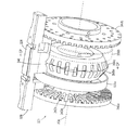
中央部220は、周方向にセグメント化されており、複数の細長い固定セグメント226と、同じ数の複数の細長い拡張セグメント228とを交互に有している。図4〜6のいずれかを見ると最も良くわかるように、24個の固定セグメント226と24個の拡張セグメント228とが交互に存在するのが好適である。拡張セグメント228は、軸線方向に延び、互いに周方向に間隔をおいて配置されており、各拡張セグメント228の端部は、組立てドラム上にカーカスを載せる上述の工程中に取り付けられるサイドウォールインサート(不図示、130に対応)の位置に対応し該インサートの寸法に関係する、外側表面の長手方向(軸線方向)位置に環状凹部(ポケット、溝)236aおよび236b(「236」と総称する、136に対応)を有するように形づくられている。ポケット236は拡張セグメントの外側表面に2つの折返しブラダー(不図示)固定点238aおよび238bも示されている図8を見ると最も良くわかる。図8および図17を見ると、拡張セグメント238、538が、ドラム上に載せられたタイヤカーカスの各部材(たとえば、サイドウォールインサート)を収容するポケット236、536を有するように形づくられているのがわかる。
【0062】
固定セグメント226は、細長く、断面が概ね矩形であり、ほぼLcに等しい長さを有している。固定セグメント226は通常、一定の幅を有するか、またはセグメントの総数に比例する幅を有している。拡張セグメント228も細長く、断面が概ね矩形であり、長さがほぼLcに等しく、通常、一定の幅を有するか、またはセグメントの総数に比例する幅を有している。拡張セグメント228も細長く、断面が概ね矩形であり、ほぼLcに等しい長さを有している。
【0063】
固定セグメントおよび拡張セグメントの数が任意の適切な数、たとえば、それぞれ24個以外の、18個から30個までの任意の適切な数であることは本発明の範囲内である。固定セグメントの数が拡張セグメントの数と厳密に等しくないことも本発明の範囲内である。拡張セグメントがすべて同じ幅を有しているわけではないことも本発明の範囲内である。同じことが固定セグメントにも当てはまる。固定セグメントおよび/または拡張セグメントのうちの選択されたセグメントは、ドラム上に載せられたインナーライナに真空を連通させるためのセグメントなどの「専用」セグメントであってよい。
【0064】
中央部220は、図4および図5に示されている折畳み(または引込みあるいは収縮)状態と、図6および図7に示されている拡張(または拡張)状態(または「完全」拡張位置)との間で拡張することができる。中央部220の拡張および折畳みを行う機構については以下に説明するが、この機構は、1つ(または2つ以上)の「半拡張」位置までの中央部の部分的な拡張に対処する。一般に、各拡張セグメント228は、ドラムの折畳み状態における第1のドラム半径からドラムの半拡張状態における第2のより大きなドラム半径まで拡張し、最後に、ドラムの完全拡張状態における第2の半径よりも大きな第3のドラム半径まで拡張することができる。
【0065】
中央部を拡張させ/折り畳む「2重円錐」機構図9〜12は、本発明の実施形態によるタイヤ組立てドラムの拡張可能な中央部320(220に対応)の主要な部材を示している。図9には、複数の(たとえば、24個の)拡張セグメント328(228に対応)の1つを示しており、複数の(たとえば、24個の)固定セグメント326(226に対応)のうちの対応するセグメントを示している。図10〜12は、拡張セグメント328が示されているが、図を明確にするために、固定セグメント326は示されていない。スピンドル308は、図10〜12に極めて概略的に示されており、図9では、図示を明確にするために省略されている。固定セグメント326のベース部材346は、図を明確にするために図9にのみ図示されている。拡張セグメント328用のベース(傾斜)部材348は図10〜12を見ると最も良くわかる。
【0066】
2つの案内部材(フランジ)340aおよび340b(「340」と総称する)が、軸線304に沿って延びる308(208に対応)上の軸線方向に互いに離れた位置に配置されている。フランジ340は、軸線304に心合わせされ互いに平行な、概ね平面状の円板の形である。各フランジ340は好適なことに、他方のフランジ340に面しておりかつ平行な内側表面を有している。フランジ340はスピンドル308に固定されており、このことは、各フランジ340がスピンドルと共に回転し、軸線方向に互いに一定距離だけ離れていることを意味している。フランジ340は中央面に心合わせされることが好ましい。各フランジ340は、図示のように、各セグメント326、328の長さLcよりも短い距離だけ離れている。
【0067】
フランジ340aおよび340bの内側表面はそれぞれ、半径方向に延びる複数の溝342aおよび342bを備えている。案内板340a上の所与の溝342aは、案内板340b上の所与の溝342bに対応し、溝342bの、スピンドル上の周方向位置と同じ周方向位置にある。この2つの所与の溝342a、342bは所与の一対の溝を構成しており、たとえば、フランジ340の内側表面の周りに等間隔に配置された24対の溝がある。これらの所与の溝対はそれぞれ、以下に述べるように、拡張セグメント328に関連する拡張セグメント支持部材(傾斜部材)348を半径方向内側および外側に案内するトラックとして機能する。
【0068】
各拡張セグメント328は、それに関連する傾斜部材348を有している。(拡張セグメント328が24個である場合、24個の傾斜部材348がある。)傾斜部材348は基本的に、平坦な平面状部材であり、4つの縁部(側面)、すなわち、拡張セグメント328を支持する頂上縁部と、2つの可動くさび部材358(以下に詳しく説明する)が作用をする傾斜面として機能する「傾斜した」底縁部と、所与の溝対の溝342aに入る第1の側縁部と、所与の溝対の溝342bに入る第2の側縁部とを有している。傾斜部材348は拡張部材328から分離されていることが好ましいが、拡張セグメント328と一体に形成されていることも本発明の範囲内である。傾斜部材348が拡張セグメント328と一体に形成されていない場合、拡張セグメント328を任意の適切な方法で傾斜部材348に取り付けることができる。
【0069】
フランジ340aおよび340bの内側表面もそれぞれ、半径方向に延びる複数の溝343aおよび343bを備えている。半径方向に延びる溝343aおよび343bのそれぞれは、半径方向に延びる溝342aと342bの間に位置している。半径方向に延びる溝343aと343bは、半径方向に延びる溝342aおよび342bよりも短い。案内板340a上の所与の溝343aは、案内板340b上の所与の溝343bに対応し、溝343bの、スピンドル308上の周方向位置と同じ周方向位置にある。これらの2つの所与の溝343a、343bは所与の一対の溝を構成しており、たとえば、フランジ340の内側表面の周りに等間隔に配置された24対の溝がある。これらの所与の溝対343a、343bはそれぞれ、後述するように、固定セグメント326に関連する固定セグメント支持部材346を受け取り固定するトラックとして機能する。ベース部材346は基本的に矩形のブロックであり、フランジの各溝間に延びており、4つの縁部(側面)、すなわち、固定セグメント326を支持する頂上縁部と、溝343aに嵌る第1の側縁部と、溝343bに嵌る第2の側縁部と、概ね平坦な側縁部とを有している。固定セグメント326が24個である場合、24対の溝343a、343b間に延びる24個のベース部材346がある。(ベース部材の側縁部は溝に入っている。)このため、各フランジの溝の総数(およびフランジの溝対の総数)は48個であり、すなわち、拡張部材328が半径方向に出入りするときに拡張部材を案内する24対の溝と、半径方向の移動が考慮されないか、または必要とされない(これに対して、固定セグメントは選択された半径位置に残ると仮定される)にもかかわらず拡張セグメント328同士の間に固定セグメント326を配置する24対の溝が存在する。ベース部材346は固定セグメント326から分離されていることが好ましいが、固定セグメント326と一体に形成されることも本発明の範囲内である。ベース部材346が固定セグメント326と一体に形成されていない場合、固定セグメント326を任意の適切な方法でベース部材346に取り付けることができる。
【0070】
各固定セグメント326は、それに関連するベース部材346を有している。(固定セグメント326が24個である場合、24個のベース部材346がある。)ベース部材346は基本的に、矩形のブロックであり、フランジの溝間を延び、4つの縁部(側面)、すなわち、固定セグメント326を支持する頂上縁部と、溝342aに嵌る第1の側縁部と、溝342bに嵌る第2の側縁部と、概ね平坦な側縁部とを有している。固定セグメント326が24個である場合、24対の溝間に延びる24個のベース部材346がある。(ベース部材の側縁部は溝に入っている。)このため、各フランジの溝の総数(およびフランジの溝対の総数)は48個であり、すなわち、拡張部材328が半径方向に出入りするときに拡張部材328を案内する24対の溝と、半径方向の移動が考慮されないか、または必要とされない(これに対して、固定セグメント326は選択された半径位置に残ると仮定される)にもかかわらず拡張セグメント328同士の間に固定セグメント326を配置する24対の溝が存在する。ベース部材346は固定セグメント326から分離されていることが好ましいが、固定セグメント326と一体に形成されていることも本発明の範囲内である。ベース部材346が固定セグメント326と一体に形成されていない場合、固定セグメント326を任意の適切な方法でベース部材346に取り付けることができる。
【0071】
図9において、固定セグメント326は、拡張セグメント328の軸線方向長さとほとんど同じ軸線方向長さを有しており、固定セグメント326と拡張セグメント328の両方の軸線方向長さLcは2つのフランジ340間の間隔よりも大きく、固定セグメントおよび拡張セグメントはフランジ340に対して「心合わせ」されていることがわかる。
【0072】
2つの偏倚部材338aおよび338b(「338」と総称する)が設けられている。一方の偏倚部材338bは図8において点線で示されている。図示を明確にするために、他方の偏倚部材338aは、図10〜12において点線で示されている。各偏倚部材338は、スピンドル308の周りの軸線方向に互いに離れた位置に配置されており、各傾斜部材348の対応する穴342aおよび342bを通って延びるゴムバンドの形であると好適である。これらのゴム部材338は、「折畳み」半径方向力を傾斜部材348に対して軸線304の方向にかける。図9に示されているように、固定セグメント326用のベース部材346は、ゴムバンド338が通って延びる穴344aおよび344bを備えてもよい。
【0073】
スピンドル308の軸線方向に互いに離れた位置(中央面の各側)に、先細りになった2つの(くさび)部材358aおよび358b(「358」と総称する)が配置されている。くさび部材358は、軸線304に心合わせされた互いに平行な概ね平面状の円板(リング(中央に穴のあいた円板であるため))の形であると好適である。くさび部材358の外側の面は先細になっている。したがって、くさび部材358は円錐台状であり、「円錐」、または「円錐状部材」、または「円錐状部材」と呼ばれることがある。くさび部材358はスピンドル308に固定されていない。その代わり、くさび部材358は、スピンドル308と共に回転するように、キー溝によってスピンドル308に固定することができるが、くさび部材358同士の間の軸線方向の距離とは無関係に互いに平行なままで、スピンドル308に沿って軸線方向(横方向)に、互いに接近しかつ離れる方向に、最小距離(互いにほぼ接触する)から最大距離まで自由に移動する。
【0074】
図10において、中央部320は折畳み(または「完全折畳み」)位置で示されている。この位置では、くさび部材358同士は互いに接近しており(たとえば、くさび部材358同士の間の距離がほぼ零であり、ベースが接触するか、またはほぼ接触している)、傾斜部材348、したがって拡張セグメント328は軸線304から最小の半径方向距離に位置する。言い換えれば、中央部320の直径はこの折畳み(引込み)位置で最小である。この折畳み位置において、中央部320の外側表面は、隣接する端部322および324(222、224に対応)の外側表面306(206に対応)とほとんど同じ直径を有する。この折畳み位置では、タイヤカーカスのインナーライナ(たとえば、以下の504)などのタイヤ部材を取り付けることができる。
【0075】
図11において、中央部320は半拡張位置で示されている。この位置では、くさび部材358同士は互いに離れており(しかし、最大限に離れてはいない)、傾斜部材348、したがって拡張部材328の、軸線304からの半径方向距離が大きくなっている。言い換えれば、中央部320の直径が大きくなっており、すなわち拡張している。この半拡張位置において、中央部320の外側表面は、隣接する端部322および324(222、224に対応)の外側表面306(206に対応)の直径よりもわずかに大きい直径を有する。この半拡張位置では、タイヤカーカスのプライ(たとえば、以下の508)などのタイヤ部材が取り付けられる。
【0076】
図12において、中央部320は完全拡張位置で示されている。この位置では、くさび部材358同士はさらに互いに離れる方向に広がっており(移動しており)(基本的に最大限に広がり、ベース同士も互いに離れている)、傾斜部材348、したがって拡張部材328の、軸線304からの半径方向距離がさらに大きくなっている。言い換えれば、中央部320の直径がさらに大きくなり、すなわちさらに拡張している。この完全拡張位置において、中央部320の外側表面は、隣接する端部322および324(222、224に対応)の外側表面306(206に対応)の直径よりもずっと大きい直径を有する。この完全拡張位置では、ビードがカーカスにしっかりと固定され、最終的なカーカス組立てステップでカーカスの折返し端部が折り返される。次に、ドラムの中央部320を部分的に折り畳む(たとえば、半拡張位置に戻す)ことができ、かつ第2段タイヤ組立て機械でトレッドパッケージを取り付けるなど、他の処理のためにカーカスを取り外すことができる。
【0077】
2つのくさび部材358は円錐(厳密に言うと、円錐台)の形をしており、ベースが互いに向かい合い(面し)、エイペックスが(切り取られているにもかかわらず)互いに離れるように同軸に(同じ軸を有するように)配置されている。2つのくさび部材358は、軸線方向の移動範囲全体にわたって常に、ドラムの中央部320の中央面から等距離に位置することが好ましい。傾斜部材348の底縁部(内側表面)はV字形であり、各くさび部材358ごとに1つの、2つの互いに交差する傾斜面を有している。このように、くさび部材358によってかけられた力は、傾斜部材348、したがって拡張セグメント328の長さに亘って均等に分散される。くさび部材358の外側縁部(表面)に沿った角度、および傾斜部材348の内側縁部(表面)に沿った対応する角度は、軸線に対して約300、特に例えば330である、200から450の間の角度であり、すなわち、軸線に対して垂直よりも平行に近い方が好適である。この角度はもちろん、くさび部材358の軸線方向の位置にはかかわらず一定である。くさび部材358同士が互いに離れれば離れるほど、拡張セグメント328は軸線304から半径方向外側に移動させられる。
【0078】
拡張セグメント328は長さLcを有している。固定セグメント326は、Lcにほぼ等しい長さを有している。フランジ340は、長さLcよりも短い距離だけ間隔をおいて配置されている。図9〜12の図示において、各フランジ340に合計で48個の溝342が示されている。上述のように、各フランジ340上のこれらの溝342のうちの24個は、半径方向外側に移動させられ半径方向内側に戻るときに傾斜部材348を案内する所与の一対の溝を構成する。図9を見ると最も良くわかるように、ベース部材346はフランジ340の中間溝対342間に延びている。さらに、ベース部材346はくさび部材358上を通る(くさび部材358の近くを通る、くさび部材358を通過する)必要がある。したがって、くさび部材358は、それぞれのベースの外側表面の周りの等間隔に離れた周方向位置に、ベース部材346が近くを通るときにベース部材346の底縁部を受け入れる24個のノッチ356を有している。これは、くさび部材358がフランジ部材340同士の間の空間を軸線方向に前後に移動できるようにしつつ、フランジ340に対して一定の周方向位置関係にくさび部材358を「固定」する働きをする。
【0079】
したがって、ドラム(すなわち、中央部320)の中央面に関して対称な拡張部材328に半径方向の力をかける横行2重円錐機構を使用して、タイヤ組立てドラムの中央部320を拡張させることができることがわかる。米国特許第5264068号のように先細り構造が1つだけである場合、このような対称性を実現することはできない。タイヤカーカスを載せる際に一様性を実現するうえで、中央面に関して対称に拡張力をかけることが重要である場合がある。
【0080】
図示されていないが、先細になったくさび部材358を軸線方向外側に移動させて中央部320を拡張させ、軸線方向内側に移動させて(互いに接近させて)中央部320の引込みを可能にするのに何らかの適切な機構を用いてよい。
【0081】
中央部320の適切な寸法は以下のとおりである。
【0082】
折畳み時直径=400mm
半拡張時直径=420mm
完全拡張時直径476mm(拡張76mm)
中央部の最小幅(Lc)250mm
中央部320を折り畳むと、ドラムの表面はほぼ連続的で、滑らかで、平坦になり、このことはインナーライナを取り付ける場合に有利である。インナーライナをドラムの表面上にしっかりと保持するために、選択されたセグメント(固定セグメントまたは拡張セグメント)を通じてドラムの表面に真空を加える手段を任意の適切な方法で設けることは本発明の範囲内である。中央部が半拡張状態であると、表面は、プライを取付けるのに有利なようにほぼ平坦になる。
【0083】
中央部を拡張させ/折り畳む「重なりリンク」機構図13〜15は、タイヤ組立てドラムの中央部320を拡張させ折り畳む機構の他の実施形態を示している。図9〜12の実施形態では、拡張用に2重円錐・傾斜機構を使用し、中央部を折り畳むのにゴムバンドを使用したが、この実施形態では、リンクは、中央部の拡張セグメントを拡張させることと収縮させることができる。
【0084】
図13〜15は、本発明の他の実施形態によるタイヤ組立てドラムの拡張可能な中央部420(320に対応)の主要な部材を示している。図15の図示では、複数の(たとえば、24個の)拡張セグメント428(328に対応)のうちの1つが示されている。図13および図14では、図示を明確にするために拡張セグメントが省略されている。この実施形態における、固定セグメントと拡張セグメントが全体的に交互に配置される構成が、前述の実施形態とほとんど同じであることが理解されよう。この実施形態を説明するにあたって、中央部420の完全折畳み位置が図13に示され、中央部420の完全拡張位置が図14に示されている。この場合、前述の実施形態と同様に、完全折畳み位置と完全拡張位置との間の任意の位置(直径)までドラムを拡張させる(または折り畳む)ことができることが理解されよう。スピンドル(308に対応)がドラムの軸線404に沿って延びているが、図示を明確にするために省略されている。図示されていないが、中央部は、前述の実施形態と同様に固定セグメント(たとえば、326)を備えている。
【0085】
スピンドル上の軸線方向に互いに離れた位置にフランジ440aおよび440b(「440」と総称する。340に対応)が配置されている。フランジ440は、前述の実施形態のフランジ340にかなり類似しており、軸線(304)に心合わせされ、互いに平行な概ね平面状の円板の形であると好適である。各案内部材440は、他方の案内部材440の内側表面に面しておりかつ平行な内側表面を有している。フランジ440は、基本的にはスピンドル308に固定されており、このことは、フランジがスピンドル308と共に回転し、互いに一定の軸線方向距離だけ離れていることを意味している。
【0086】
フランジ440aおよび440bの内側表面はそれぞれ、半径方向に延びる複数の溝442aおよび442bと、溝442aおよび442b同士の間に位置する溝443aおよび443bとを備えている。この場合も、これは、前述の実施形態の溝342aおよび342bならびに343aおよび343bに相当する。案内板440a上の所与の溝442aは、案内板440b上の所与の溝442bに対応し、溝442bの、スピンドル上の周方向位置と同じ周方向位置にある。これらの2つの所与の溝442a、442bは一対の溝を構成しており、たとえば、フランジの内側表面の周りに等間隔に配置された24対の溝がある。各溝対は、後述するように、拡張セグメント支持部材、すなわちベース(支持)部材448(348に対応)が軸線から半径方向内側および外側に移動するときに該部材448を案内するトラックとして機能する。
【0087】
各拡張セグメント428は、それに関連する支持部材448を有している。(拡張セグメントが24個である場合、24個のベース部材がある。)支持部材448は基本的に平坦な平面状部材であり、4つの縁部(側面)、すなわち、拡張セグメント328を支持する頂上縁部と、所与の溝対の溝442aに入る第1の側縁部と、所与の溝対の溝442bに入る第2の側縁部とを有している。支持部材448は底縁部を有しているが、この縁部の形状は(傾斜部材348の底縁部傾斜面と比べて)特に重要ではない。支持部材448は拡張部材428から分離されていることが好ましいが、拡張セグメント428と一体に形成されていることも本発明の範囲内である。支持部材448が拡張セグメント428と一体に形成されていない場合、拡張セグメント428を任意の適切な方法で支持部材448に取り付けることができる。
【0088】
スピンドル上の軸線方向に互いに離れた位置(中央面の各側)に2つの案内リング(ハブ)458aおよび458b(「458」と総称する)が配置されている。案内リング458は、軸線404に心合わせされ互いに平行な概ね平面状の円板(中央に穴のあいた円板であるため、リンク)の形であると好適である。案内リング458はスピンドルに固定されていない。その代わり、案内リング458は、スピンドルと共に回転するように、キー溝(スプライン)によってスピンドルに固定することができるが、案内リング458同士の間の軸線方向の距離とは無関係に互いに平行なままで、スピンドルに沿って軸線方向に、互いに接近しかつ離れる方向に、最小距離(互いにほぼ接触する)から最大距離まで自由に移動する。
【0089】
案内リング458と支持部材448との間に重なりリンク機構460が設けられている。このリンク460機構は、
一方の案内リング458(458a、図の左側)にピボット運動可能に取り付けられた一方の端部と、支持部材448の一方の端部(図の右側)に隣接して(該端部の近くに)ピボット運動可能に取り付けられた反対側の端部を有する第1の細長いリンク462と、
他方の案内リング458(458b、図の右側)にピボット運動可能に取り付けられた端部と、支持部材448の反対側の端部(図の左側)に隣接して(該端部の近くに)ピボット運動可能に取り付けられた反対側の端部を有する第2の細長いリンク464とを有している。
【0090】
リンク462とリンク464は重なり合っている(互いに交差している)が、「はさみ」型連結部材のように、互いにピボット運動可能に取り付けられているわけではなく、また2リンク「トグル」型連結部材の場合のように、互いに平行であるわけではない。
【0091】
図13(図10に対応)において、中央部420は折畳み(すなわち「完全折畳み」位置で示されている。この位置では、案内リング458同士が互いに離れており(基本的に最大限に離れている)、支持部材448、したがって拡張セグメント428は軸線404から最小半径方向距離に位置する。言い換えれば、中央部420の直径はこの折畳み位置で最小である。この折畳み位置において、中央部420の外側表面は、隣接する端部(322および324)の外側表面(306)とほとんど同じ直径を有する。この折畳み位置では、タイヤカーカスのインナーライナが取り付けられる。
【0092】
図14(図12に対応)において、中央部420は完全拡張位置で示されている。この位置では、くさび部材458同士が互いに接近しており(たとえば、くさび部材458同士の間の距離がほぼ零であり)、支持部材448、したがって拡張部材428の、軸線504からの半径方向距離が最大になっている。言い換えれば、中央部420は完全に拡張している。この完全拡張位置において、中央部420の外側表面は、隣接する端部(たとえば、222、224)の外側表面(306)の直径よりもずっと大きい直径を有する。ドラムを完全拡張位置にするのと同時に、別々に作動させられるビードロック(不図示)によって、ビードがしっかりと固定される。次に、最終的なカーカス組立てステップでカーカスの折返し端部を折り返すことができる。次に、ドラムの中央部420を部分的に折り畳む(たとえば、半拡張位置に戻す)ことができ、かつ第2段タイヤ組立て機械でトレッドパッケージを取り付けるなど、その後の処理のために、折り畳まれたビードロックおよびカーカスを取り外すことができる。
【0093】
折畳み位置(図13)において、リンク462および464は共に、軸線404にほぼ平行である。たとえば、軸線404に対する角度は19.60である。拡張位置(図14)において、リンク462とリンク464は、軸線303に対して平行な角度と垂直な角度との概ね中間の角度、軸線303に対して例えば46.20の角度をなしている。これによって、良好な動作範囲を有する比較的小形の機構が得られる。
【0094】
図示されていないが、中央部420は、案内リング458同士の間隔によって決まる、折畳み位置と完全拡張位置との間の任意の直径まで拡張することができる。たとえば、半拡張位置では、タイヤカーカスのプライが取り付けられる。2つの案内リング458が、その位置範囲内で移動している間、ドラムの中央部420の中央面から等距離にとどまることが好ましい。このように、支持部材448および拡張セグメント428の長さ(Lc)に沿って力が均等に(対称に)分散される。
【0095】
重なり連結機構を用いるこの例では、案内リング458同士の間隔と中央部420の直径との関係は反比例であり、案内リング458同士が接近するにつれて、中央部の直径が大きくなる。前述の例(くさび/傾斜)では、案内リング458同士の間隔と中央部420の直径との関係は正比例であり、案内リング458同士が接近するにつれて、中央部の直径が小さくなる。しかし、いずれの場合も、中央部320および420の直径は、くさび部材358同士の間隔または案内リング458458同士の間隔に比例(それぞれ正比例または反比例)する。
【0096】
図13〜15の重なりリンク機構は、ドラムの拡張範囲全体に亘って、中央面に関して対称拡張セグメント428に力をかけることができる点に関して、たとえば、前述の米国特許第4929298号に示されたトグルリンク機構よりも優れている。2つのリンクが互いに平行に連動するトグルリンク機構は、中心面に関して本質的に対称ではない。この対称性は、前述の(くさび)実施形態と同様に、タイヤカーカスを組立てドラムに載せる際に一様性を実現するうえで非常に重要である。
【0097】
図13〜15の重なりリンク機構の実施形態は、以下の点で図9〜12のくさび/傾斜実施形態に類似している。
【0098】
共に、タイヤ組立てドラムの中央部(220、320、420)を拡張させ折り畳む。
【0099】
共に、中央部の拡張セグメント(228、328、428)に作用する。
【0100】
共に、中央部の固定セグメント(226、326、426)には作用しない。
【0101】
共に、拡張部材(328、428)を支持する傾斜部材(348)または支持部材(448)を案内する溝(342、442)を持つフランジ(340、440)を使用する。
【0102】
共に、中央部の拡張/折畳みを行うように軸線方向に移動する部材(358、458)を有する。
【0103】
共に、中央面に関して対称に拡張セグメントに拡張力をかける。
【0104】
拡張セグメント428に加えられる力の中央面に関する対称性は重要である。上述のように、一方に傾けられたカーカスプライ(タイヤの一方の側のコードが他方の側のコードよりも長い)は、静的不釣合いおよび半径方向力変動を含む様々なタイヤ非一様性問題を引き起こすことがある。本発明は、このような非一様性、すなわち、ドラムの正確でない(たとえば、非円筒状の)拡張の1つの潜在的な原因に対処する。
【0105】
どちらの実施形態においても、中央部(320、420)を折り畳むと、ドラムの表面はほぼ連続的で、滑らかで、平坦になり、このことはインナーライナを取り付けるのに有利である。インナーライナをドラムの表面上にしっかりと保持するために、選択されたセグメント(固定セグメントまたは拡張セグメント)を通じてドラムの表面に真空を加える手段を任意の適切な方法で設けることは本発明の範囲内である。中央部を半拡張させると、表面はやはりほぼ平坦になり、プライを取り付けるうえで有利である。どちらの実施形態も、中央部を拡張させるのにローラスクリューシステムを用いることができる。くさび358または案内リング458を移動させる機構は主として、全体的なドラム構造に存在する他の要因に依存し、場合に応じて作り替えることができる。
【0106】
図13〜15の重なりリンク機構の実施形態は、以下の点で図9〜12のくさび/傾斜実施形態と異なる。
【0107】
くさび/傾斜実施形態では、中央部320を折り畳むのにゴムバンド338が用いられる。
【0108】
重なりリンク機構では、リンク462、464自体が中央部を折り畳む。
【0109】
くさび/傾斜実施形態では、くさび358同士が軸線方向に互いに離れたときに中央部320が拡張し、くさび358同士が一緒に動いたときに中央部320が引き込む。
【0110】
重なりリンク機構では、案内リング458同士が互いに接近したときに中央部420が拡張し、案内リング458同士が互いに離れたときに中央部420が引き込む。
【0111】
重なりリンク機構は、比較的狭い幅(Lc)で比較的大きな拡張範囲をもたらし、ドラムの収縮幅を最小限に、たとえば250mm(くさび実施形態の場合)から200mm(リンケージ実施形態の場合)に抑える傾向がある。
【0112】
リンク機構実施形態の中央部420のいくつかの例示的な寸法を表1に示す。
【0113】
【表1】

【0114】
走行距離延長タイヤ図17は、本発明による、タイヤ組立てドラムに載せられたときの例示的なタイヤカーカスの部分断面図である。拡張セグメント528の端部が図示されている。まず、中央スリーブ502がドラムの表面上に設置され、拡張セグメント528上に広げられる。上方の折返しブラダー(bladder)503および下方の折返しブラダー505はドラムを越えて延びている。タイヤカーカスは、以下の主要な部材を以下の順序で有している。
【0115】
インナーライナ504
第1のサイドウォールインサート(ピラー)506
第1のプライ(プライ1)508
第2のサイドウォールインサート(ピラー)510
第1のプライ(プライ1)521
ビード514
エイペックス516
チェーファー518
サイドウォール520
チッパー(chipper)、ガムトウガード(gum toeguard)、織物トウガードのような他の部材を必要に応じてカーカスに付加してよいが、それらが本発明の特別な一部を構成することはない。
【0116】
タイヤカーカスへのビードの取付け
図1および図2は、それぞれタイヤ組立てドラム102および122に載せられた、タイヤカーカス上の所定の位置にあるビード114および134を示している。上述のように、各ビード114および134は、ほぼ伸長不能な円形のループであり、それぞれプライ112または132のODとほぼ等しいか、または好ましくは該ODよりもわずかに大きい内径(「ID」)を有している。ビード114および134は、それぞれインサート110および130のわずかに軸線方向外側に位置ものとして示されている。
【0117】
図3から6は、概ね円筒状であり、2つの端部202aおよび202bと、2つの端部202a、202b間に延びる回転軸線204と、円筒状の外側表面206とを有するタイヤ組立てドラム202を示している。上述のように、ドラム202は、概ね円筒状であり軸線204に心合わせされた中央部220を有している。ドラム202は、中央部220と同軸であり、中央部220の軸線方向の一端に配置された第1の端部222を有している。ドラム202は、中央部220と同軸であり、中央部220の軸線方向に反対側の端部に配置された第2の端部224を有している。2つの端部222および224は、互いにほぼ同じである(すなわち、互いに鏡像の関係にある)。端部222および224は中央部220の軸線方向外側に位置している。
【0118】
一般に、ドラムの各端部ごとに1つの、タイヤ用の2つのビードを、組立てドラム上に載せられているカーカスのそれぞれの端部上に設置してよい。以下の図で説明するように、タイヤ組立てドラムの2つの端部を、ビードを「固定する」ように拡張させることができる。したがって、各端部は、その端部に配置されたビードを「固定する」ように拡張する「ビードロック組立体」を含んでいる。このことについては以下に詳しく説明する。
【0119】
ドラムの中央部が拡張可能であり、(たとえば)複数の細長い固定セグメント226と、同数の複数の細長い拡張セグメント228とを交互に有していることも想起されよう。ビードは通常、ビードを保持し、組立てドラムに載せられているカーカスの周りの所定の位置にビードを移動させるビードホルダを使用することによってドラムのそれぞれの端部上に移動させられる。2つのビードが取付けられる位置は概ね各端部の内側縁である。
【0120】
図18および19は、それぞれ閉位置および開位置にあるビードホルダ622を示している。ビードホルダ622は支持体(ベース)602およびリング604を有している。リング604は、内径「d」を有している。リング604は3つのセグメント、すなわち左のセグメント604aと、中央のセグメント604bと、右のセグメント604cとを有している。3つのセグメント604a、604b、および604cは通常、弧範囲が等しく、すなわち、それぞれ約1200である。中央のセグメント604bは支持体602に固定されている。左のセグメント604aおよび右のセグメント604cは、中央のセグメント604bにピボット運動可能に取り付けられる(不図示)か、または支持体602に直接取り付けられている。
【0121】
左のセグメント604aを閉位置(図18)から開位置(図19)にピボット運動させる機構606が設けられている。右のセグメント604aを閉位置(図18)から開位置(図19)にピボット運動させる機構607が設けられている。開位置では、左のセグメント604aおよび右のセグメント604cの遠位端同士が、タイヤドラム(特に、ドラムに載せられているカーカス)の直径(OD)よりも大きい距離「e」だけ離れ、したがって、ドラムホルダを、ドラムから(ドラムに対して半径方向に)持ち上げるだけでドラムから取り外すことができる。開いたビードホルダ622を軸線634を有するドラム(図示せず)から取り外すこの半径方向は、矢印636によって示されている。
【0122】
複数の磁石608がリング604の内側縁部のすぐ内側に配置されている。これらの磁石608は、リング604上に(図示を明確にするために一部分のみが示されている)ビード612を保持する。磁石608の磁力は、ビード612を保持するのに十分であるが、ビードホルダ622をドラムから取り外すときにビード612をドラム上、またはドラムに載せられたタイヤカーカス上の所定の位置に止めるのに弱い。
【0123】
図17に関して上記で説明したように、中央のスリーブ502がドラムの表面に設置され、ドラムの中央部の拡張セグメント528上を延びている。上部の折返しブラダー503および下方の折返しブラダー505は、ドラムの隣接する端部を越えて延びている。折返しブラダーの構成および動作について以下に詳しく説明する。
【0124】
拡張可能な端部を有する組立てドラム図20はタイヤ組立てドラム700(202に対応)を示している。ドラム700は概ね円筒状であり、2つの端部(202a、202bに対応)と、軸線704(204に対応)と、概ね円筒状の外側表面706(206に対応)とを有している。ドラム700は、2つの端部間に軸線方向の全長(Lに対応)を有している。ドラム700は、概ね円筒状であり、軸線704に心合わせされた中央部720(220に対応)を有している。中央部720は幅(Lcに対応)を有している。ドラム700は、中央部720と同軸であり、中心部720の軸線方向の一端に配置された第1の端部722(222に対応)を有している。ドラム700は、中央部720と同軸であり、中心部720の軸線方向の反対側の端部に配置された第2の端部724(224に対応)を有している。2つの端部722および274は、本発明のために、互いにほぼ同じである(すなわち、互いに鏡像の関係にある)。
【0125】
図3,4に関して上記で説明したように、中央部720は、周方向に分割されており、複数の細長い固定セグメント(不図示、226に対応)と、同じ複数の細長い拡張セグメント728(228に対応)とを交互に有している。拡張セグメント728は、軸線方向に延び、互いに周方向に間隔をおいて配置されており、各拡張セグメント728の端部は、組立てドラム上にカーカスを載せる工程中に取り付けられるサイドウォールインサート(たとえば、506、510)の位置に対応し該インサートの寸法に関係する、外側表面における長手方向(軸線方向)位置に環状凹部(ポケット、溝;236aおよび236bに対応)を有するように形作られている。拡張セグメント728は、それぞれブラダー714a、714bまで延びる中央のスリーブ713a、713bを固定する固定点(238aおよび238bに対応)も有している。本発明は特定の寸法に限定されないが、タイヤ組立てドラムの例示的な寸法は上記に示されている。端部722および724の例示的な寸法は、図20に基づいて、中央部720の寸法から外挿することができる。
【0126】
上述したように、中央部720(220)は、折畳み(または引込みあるいは収縮)状態と拡張状態(または「完全」拡張位置)との間で拡張できるのが好適であり、中央部の拡張および折畳みを行う機構については上記に説明したとおりであり、この機構は、1つ(または2つ以上)の「半拡張」位置までの中央部の部分的な拡張に対応している。上記では、ドラムに載せられたタイヤカーカスの、中央部の様々な拡張位置(状態)に、様々なタイヤ部材を取り付けることができることを説明した。
【0127】
図20は、中央部720の各端部に1つの、2つの端部722および724を示している。端部722、724は、以下に詳しく説明するように、ドラムの端部の様々な拡張位置(状態)に載せられたタイヤカーカス上に、選択されたタイヤ部材(たとえば、ビード)を取り付けるビードロック組立体を拡張させる機構を含む、拡張可能なビードロック組立体726a、726bを備えている。これら2つの端部722、724は基本的に互いに鏡像の関係にあるので、一方の端部のみについて詳述すれば十分である。
【0128】
図20は、端部722、724上に配置された折返しブラダー示している。端部722の外側表面上に底部の折返しブラダー712aが配置されている。端部724の外側表面上に底部の折返しブラダー712bが配置されている。端部722の外側表面上の底部の折返しブラダー712aの上に頂上部の折返しブラダー714aが配置されている。端部724の外側表面上の底部の折返しブラダー712bの上に頂上部の折返しブラダー714bが配置されている。一般によく知られているように、折返しブラダー712a、712bおよび714a、714bは、それぞれのビード734aおよび734b(134aおよび134b、ならびに512にも対応)の周りでグリーンカーカスの折返し端部を折り返す。
【0129】
拡張可能なビードロック組立体端部722および724のそれぞれは、ビードロック組立体726a、726b(総称して「726」)を備えている。端部722および724は実質的に互いの鏡像の関係にあるので、単一の端部722のみのビードロック組立体726について詳述すれば十分である。
【0130】
図20に示されているように、端部722は、以下の主要な部材、すなわち、
第1のピストン「P1」と、
第2のピストン「P2」と、
キャリアリング「CR」と、
複数の細長いセグメント「S」と、
複数の細長いリンク(リンクアーム)「K」とを有するビードロック組立体726aを備えている。
【0131】
ピストンP1およびP2の各々は、概ね平坦な円板の形をしており、共に軸線704に心合わせされており(したがって、「同軸」であり)、各々、他方と同じ外径を有している。軸線704は、ピストンP1およびP2の平面に垂直である。ピストンP1およびP2はシリンダブロック(または単に「シリンダ」)730内に配置されており、シリンダブロック730の円筒状内部732(「ピストン部」)はピストンP1およびP2の外径に対応する内径を有している。ピストンP1およびP2は、シリンダ730のこのピストン部732内に配置されており、(中央部720に対して)軸線方向内側および外側に自由に移動することができる。
【0132】
以下に詳しく説明するように、ピストンP1およびP2は、その内側(中央部720に近づく方)面または外側(中央部720から離れる方)面に選択的に空気圧(油圧)をかけることによって軸線方向内側および外側に移動するので、ピストンP1およびP2の外側縁部に適切なシールが設けられている。
【0133】
第1のピストンP1は第2のピストンP2の軸線方向外側(中央部720から離れる方)に配置されている。第2のピストンP2は第1のピストンP1の軸線方向内側に配置されている。図20において、2つのピストンP1およびP2は互いに当接するように示されており、ビードロック組立体726は折畳み位置にある。以下に詳しく説明するように、2つのピストンP1およびP2は軸線方向に移動可能であり、移動する際、キャリアリングCRを軸線方向に移動させる。複数のリンク(リンクアーム)「K」は、キャリアリングCRと拡張可能なセグメントSの半径方向内側端部との間を延びている。リンクKの一端はキャリアリングCRにピボット運動可能に連結されており、他方の端部は、拡張可能なセグメントSの半径方向内側端部にピボット運動可能に連結されている。拡張可能なセグメントSは、軸線方向に移動しないようによっており、半径方向の移動に制限されている。キャリアリングCRが軸線方向内側に(中央部720に向かう方へ)移動すると、拡張可能なセグメントSは半径方向外側に移動する。その結果、キャリアリングCRが軸線方向外側に(中央部から離れる方へ)移動すると、拡張可能なセグメントSは半径方向内側に移動する。拡張可能なセグメントSは細長く、断面がほぼ方形であると好適である(たとえば、図28参照)。
【0134】
シリンダ730の外側端部、特にシリンダ730のピストン部732の外側端部に端板734が配置されている。この端板734は、ピストン部732の外側端部を形成しており、該外側端部を閉じ、ピストンP1およびP2の外側への移動を制限する。端板734はまた、ピストン部732の外側端部を密封する。環状凸部736は、シリンダ730の内側表面の、端板734から軸線方向内側に離れた位置から延びており、ピストン部732の内側端部を形成している。この環状凸部736は、ピストンP1およびP2の内側への移動を制限する。ピストンP1およびP2は、シリンダ730のピストン部732内を、端板734と環状凸部736との間で軸線方向に自由に移動することができる。このようにして、気密ピストン部732が形成される。
【0135】
2つの空気圧(空気)ライン742および744が図20に示されているが、これらの空気圧ラインは共に、端板734で終わる端部を有しており、シリンダ730の外側端部に配置されている。上述のように、これらのライン742および744内の圧力は、第3のライン745(図23に最も良く示されている)内の圧力とともに、ピストンP1およびP2の移動を制御する。
【0136】
図20に示されているように、空気圧ライン744は、加圧された空気を空気通路PW1を通してピストンP1を越えた位置まで送る。空気圧ライン742は、加圧された空気を空気通路PW2を通してピストンP1とピストンP2との間に送る。図示されていないが、空気圧ライン742は、加圧された空気を不図示の空気通路PW3を通してピストンP2と環状凸部736との間に送る。
【0137】
上述のように、拡張可能なセグメントSは、軸線方向に移動しないようになっており、半径方向の移動に制限されている。図20に示されているように、拡張可能なセグメントSは、シリンダ731aの内側(中央部720に近づく方向)端部730aと、端部722の内側端部722aにある端板723aとの間に形成された半径方向流路内を半径方向に移動する。拡張可能なセグメントSは細長いシャフトの形態をしていると好適である。周方向のセグメントであるフィンガセグメント「F」が拡張可能なセグメントSの半径方向外側端部に配置されている。例えば12個の複数の拡張可能なセグメントSと、例えば12個の同数の複数のフィンガセグメントFがある。フィンガセグメントFは、端部722の周方向に約300などの間隔をおいて配置されている。
【0138】
タイヤ組立てドラム700の端部722および724用の拡張可能なビードロック組立体726の発明について、図20を参照して概略的に説明した。以下の図には、様々な位置または状態(たとえば、折畳み位置、部分拡張位置、完全拡張位置)のビードロック組立体を含む、ビードロック組立体の動作の詳細が示されている。
【0139】
図21、22、23、および24は、完全折畳み状態のタイヤ組立てドラム700の端部722を示している。これは、図9〜12において、中央部(220)が完全折畳み状態で示されている状況といくらか類似している。図25および図26は、半拡張(または半折畳み)状態のタイヤ組立てドラム700の端部722を示している。これは、図11において、中央部(220)が半拡張(または半折畳み)状態で示されている状況といくらか類似している。図27および図28は、完全拡張状態のタイヤ組立てドラム700の端部722を示している。これは、図12において、中央部(220)が完全拡張状態で示されている状況といくらか類似している。
【0140】
上述のように、ビードロック組立体726の機械的部材には、
第1のピストン「P1」と、
第2のピストン「P2」と、
キャリアリング「CR」と、
複数の細長いセグメント「S」と、
複数の細長いリンク(リンクアーム)「K」と、
複数のフィンガセグメント「F」とが含まれる。
【0141】
ビードロック組立体726は、以下の機械的部材、すなわち、
ピストンP1に関連する3つのロッドR1P1、R2P1、R3P1と、
3つのロッドR1P1、R2P1、R3P1に関連する停止ブロックB1と、ピストンP2をCRに連結する3つのロッドR1P2、R2P2、R3P2とをさらに有している。
【0142】
3つの空気圧ライン742、743、および744は加圧された空気を以下の位置、すなわち、
ピストンP1を内側に移動させるためにピストンP1の外側、
ピストンP2を内側に移動させるためにピストンP1とピストンP2との間、ピストンP1およびP2を引き込みビードロック組立体を引き込ませるためにピストンP2の内側に供給するために、シリンダブロック(730)内の関連する通路PW1、PW2、およびPW3と共に設けられている。
【0143】
次に、使用サイクルについて、まずビードロック組立体726が引き込まれた状態(端部722の折畳み状態)から説明する。これは図21、図22、図23、および図24に最も良く示されている。ピストンP1およびP2は最も外側の位置にあり、ピストンP1は端板734に当接しており、ピストンP2はピストンP1に当接している。拡張可能なセグメントSは、フィンガセグメント下と同様に引込み位置にある。フィンガセグメントFは、ドラム内の中心線に対して第1の半径にある。端部722は、直径が最小の状態にある。
【0144】
図25および図26を見ると最も良くわかるように、第1の拡張ステップ(半拡張状態)では、加圧された空気がライン744、通路PW1を通してピストンP1の外側表面に供給される。これによってピストンP1が軸線方向内側に中央部720の方へ移動する。ピストンP1は、内側に移動する際、ピストンP2を内側に押す。ピストンP1の軸線方向内側への移動は、以下に説明するように、端板734を通ってピストンP1内へ延びる3つのロッドR1P1、R2P1、R3P1によって制限される。3つのロッドR1P1、R2P2、R3P2は軸線方向にピストンP2とキャリアリングCRとの間に延びている。したがって、ピストンP2が内側に移動すると、キャリアリングCRは内側に移動する。細長いリンクKは、キャリアリングCRと拡張可能なセグメントSとの間に延びている。細長いキャリアリングCRが内側に移動すると、拡張セグメントSは半径方向外側に移動する。複数のフィンガセグメントFは、細長い拡張セグメントSの外側端部に配置されている。フィンガセグメントFが半径方向外側に、第1の半径よりも大きい第2の半径まで移動すると、端部722内のビードロック組立体726の直径が大きくなる。したがって、加圧された空気がライン744に供給されると、ビードロック組立体726は部分的に拡張する。
【0145】
3つのロッドR1P1、R2P1、R3P1は、好ましくは軸線704の周りの等間隔に離れた周方向位置(1200)において、端板734を通ってピストンP1内に延びている。これらのロッドは、停止ブロックB1と共に、ピストンP1の軸線方向内側への移動を制限する。これは、ビードロック組立体726の中間部分拡張状態である。この中間位置を調整するには、様々な長さの停止ブロックB1を使用することができる。
【0146】
図27および28を見ると最も良くわかるように、ビードロック組立体がさらに拡張することは、加圧された空気を、ライン742を通して、ピストンP1とピストンP2との間にある通路PW2内に供給することによって行われる。これによってピストンP2がさらに内側に移動し、それにより、ロッドR1P2、R2P2、R3P2を介してキャリアリングCRを内側に移動させる。キャリアリングCRがさらに内側に移動すると、リンクKが、拡張可能なセグメントSおよびフィンガセグメントFを半径方向外側に、第2の半径よりも大きい第3の半径まで移動させられ、それによってビードロック組立体726の直径を完全拡張状態まで大きくする。このステップでは、図27に示されているように、ピストンP1は正常に引き込む(端板734によって停止されるまで軸線方向外側に移動する)。
【0147】
ビードロック組立体726の引込みは、加圧された空気を、ライン743を通し通路PW3(図21参照)内を通って、ピストンP2の軸線方向内側に供給することによって行われる。同時に、ライン742および744内の加圧された空気が停止される。ライン743内の加圧された空気によってピストンP2が軸線方向外側に移動し、それによって、ロッドR1P2、R2、R3P2を介してキャリアリングCRを軸方向外側に移動させ、それによってリンクKを介して、拡張可能なセグメントSおよびフィンガ部材Fを半径方向内側に移動させ、それによって、ビードロック組立体726の直径を完全折畳み状態まで小さくする。ピストンP2は、ピストンP1によって停止されるまで軸線方向外側に移動する。前のステップで、ピストンP1が引き込めないように、中間位置に拘束されている場合、ピストンP1をこの非引込み位置に選択的に維持することができ、ピストンP1によってピストンP2の軸線方向外側への移動が制限され、それによってビードロック組立体の部分折畳み状態が確立される。その後、ピストンP1を完全に引き込めるようにすることによって、ピストンP2はさらに軸線方向外側に移動することができ、したがって、ビードロック組立体は完全折畳み状態を実現することができる。
【0148】
したがって、端部720(もちろん、端部724も)を選択的にかつ制御可能に拡張させ折り畳むことができることは明らかである。基本的に外側表面全体を拡張させ折り畳むことができる中央部720とは異なり、端部722、724において拡張し折り畳まれるのは小さいセグメント、すなわち、複数のフィンガセグメントFによって形成されるバンドだけである。セグメントFによって形成されるバンドは、軸線方向にそれぞれの端部722、724の内側端部から外側端部の方へ延び、端部の外周全体に亘って周方向に延びている。フィンガセグメントF、したがってバンドは、ドラムの端部722、724の折畳み状態における第1の半径から、中間部分拡張状態における第2の半径まで拡張し、次に、ドラムの端部の完全拡張状態における第3の半径まで拡張することができる。
【0149】
ビードロック組立体726の拡張/収縮を要約すると、加圧された空気を第1の通路744を通し第1の通路PW1を介して第1のピストンP1の外側に供給すると、第1のピストンP1が軸線方向内側に移動し、第2のピストンを、ロッドR1P1、R2P1、R3P1によって拘束されるまでやはり軸線方向内側に押し、したがって、ビードロック組立体726が部分的に拡張する。加圧された空気を第2の通路742を通し第2の通路PW2を介して第1のピストンP1の内側と第2のピストンの外側との間の位置に供給すると、第2のピストンP2が、凸部736によって停止されるまで、軸線方向内側にさらに移動し、したがって、ビードロック組立体726が完全に拡張する。加圧された空気を第3の通路743を通し第3の通路PW3を介して第2のピストンP2の内側の位置に供給すると、第2のピストンP2が軸線方向外側に移動し、したがって、上述のように、ビードロック組立体726が、第1のピストンP1によって停止されるまで完全に折り畳まれる。
【0150】
工程の流れ
次に、中央部720と端部722および724の両方の膨張を説明する、組立てドラムにタイヤカーカスを載せる動作の例示的なシーケンスについて説明する。
【0151】
(a)まず、折畳み位置(たとえば、図9、10、13、21、22、23、24参照)において、平坦な取付け面を形成する中央のスリーブ713a、713b上にインナーライナ504を取り付ける。
【0152】
(b)次に、ドラム全体に亘って平坦な表面が形成されるように(たとえば、図11、25、26を参照されたい)、中央部720と端部722および724を共に中間状態まで拡張させる。
【0153】
次に、中間状態で、中央部220の拡張可能なセグメント228上の凹部236にピラーインサート506を取り付ける。
【0154】
次に、中間状態で、第1のプライ508を取り付ける。
【0155】
次に、中間状態で、第1のプライ508上およびピラーインサート506のかなり上方にポストインサート510を取り付ける。
【0156】
次に、中間状態で、第2のプライ512を取り付ける。
【0157】
(c)次に、ビード保持装置622を用いてビード514、716a、716bを所定の位置に移動させ、ビードロック組立体726のフィンガF上に保持する。
【0158】
(d)次に、フィンガFが拡張不能なビードをつかむように、ビードロック組立体726と中央部720を共に完全拡張位置まで拡張させる。ビードが上方の折返しブラダー714a、714bの端部に固定され、シールを形成する。
【0159】
(e)次に、上方の折返しブラダー714a、714bを拡張させ、ビード514、716a、716bの周りでのタイヤ部材の折返しを開始させる。
【0160】
(f)引き続き、底部の折返しブラダーを拡張させ、ビードの周りのタイヤ部材を折返しを完了する。
【0161】
(g)次に、ドラムおよびビードロック組立体が完全拡張位置にある間に、カーカスにサイドウォールを取り付けることができる。
【0162】
(h)次に、ビードロック組立体726および中央部720を折り畳む。空気によってピストンP2がドラムの中央から離れることによりフィンガが確実に解放されるため、ビードロック組立体726が強制的に折り畳まれることに留意されたい。
【0163】
(i)最後に、タイヤカーカスのビード上に移送リングを移動させることができる。真空によってカーカスをドラムから引き離し、グリーンタイヤカーカスをドラムから取り外す。
【図面の簡単な説明】
【図1】従来技術による、タイヤカーカスが載せられたタイヤ組立てドラムの概略断面図である。
【図2】従来技術による、タイヤカーカスが載せられたタイヤ組立てドラムの概略断面図である。
【図3】本発明によるタイヤ組立てドラムの斜視図である。
【図4】本発明による、折畳み位置(状態)にある図3のタイヤ組立てドラムの中央部の斜視図である。
【図5】本発明による、図4に示されている中央部の断面図である。
【図6】本発明による、拡張位置(状態)にある図3のタイヤ組立てドラムの中央部の斜視図である。
【図7】本発明による、図6に示されている中央部の断面図である。
【図8】本発明による、図3のタイヤ組立てドラムの中央部の代表的な拡張セグメントの斜視図である。
【図9】本発明の実施形態によるタイヤ組立てドラムの中央部の斜視図である。
【図10】完全折畳み状態にある図9の中央部の断面図である。
【図11】半拡張状態にある図9の中央部の断面図である。
【図12】完全拡張(または半拡張)状態にある図9の中央部の断面図である。
【図13】完全折畳み状態にある中央部を示す、本発明の他の実施形態によるタイヤ組立てドラムの中央部の断面図である。
【図14】完全拡張位置にある中央部を示す、本発明の他の実施形態によるタイヤ組立てドラムの中央部の断面図である。
【図15】本発明による、図13および図14の他の実施形態のリンク機構がどのように働くかを示す概略図である。
【図16】本発明による、リンク機構の部材の他の実施形態の平面図である。
【図17】本発明によるタイヤ組立てドラムに載せられたタイヤカーカスの部分断面図である。
【図18】閉位置での本発明の方法の実施に関連して使用できる従来技術のビードホルダの概略平面図である。
【図19】開位置での図18のビードホルダの概略平面図である。
【図20】本発明による、拡張可能な端部を有するタイヤ組立てドラムの詳細断面図である。
【図21】完全折畳み位置(状態)での図20のタイヤ組立てドラムの端部の断面図である。
【図22】図21の線7B−7Bに沿った、図21に示されている端部の断面図である。
【図23】図20のタイヤ組立てドラムの端部の外側端部の斜視図である。
【図24】端部内のピストン用の停止機構の詳細を示す、図21と同様な断面図である。
【図25】半拡張(または半折畳み)状態にある図16のタイヤ組立てドラムの端部を示す、図21または図22と同様な断面図である。
【図26】半拡張(または半折畳み)位置(状態)にある図25の端部の外側端部の斜視図である。
【図27】完全拡張状態にある図16のタイヤ組立てドラムの端部を示す、図21または図24と同様な断面図である。
【図28】完全拡張位置(状態)にある図27の端部(722)の内側端部の斜視図である。
【符号の説明】
102、122、202、700 タイヤ組立てドラム
102a、102b、122a、122b、202a、202b、208a、208b 端部
104、124、204 回転軸
106、126、706 円筒状の外側表面
108、128、504 インナーライナ
110a、110b、130a、130b インサート
112、508 第1のプライ
114a、114b、134a、134b、514、612、734a、734b ビード
136a、136b、236a、236b 環状凹部
220、420、720 中央部
222 第1の端部
224 第2の端部
226、326 固定セグメント
228、238、328、428、528、538、728 拡張セグメント
236、536 ポケット
238a、238b 固定点
304、404、704 軸線
308 スピンドル
338a、338b 偏倚部材
340、440a、440b フランジ
340a、340b 案内部材
342a、342b、442a、442b、443a、443b 溝
346 ベース部材
348 傾斜部材
358 可動くさび部材
358a、358b 先細りの部材
448 支持部材
458a、458b 案内リング
460 重なりリンケージ機構
462 第1の細長いリンク
464 第2の細長いリンク
502、713a、713b 中央のスリーブ
503 上方の折返しブラダー
505 下方の折返しブラダー
506 第1のサイドウォールインサート
510 第2のサイドウォールインサート
512 第2のプライ
516 エイペックス
518 チェーファー
520 サイドウォール
602 支持体
604 リング
604a 左のセグメント
604b 中央のセグメント
604c 右のセグメント
607 機構
622 ビードホルダ
712a、712b 底部の折返しブラダー
714a、714b 頂上部の折返しブラダー
722 第1の端部
722a、730a 内側端部
723a、734 端板
724 第2の端部
726a、726b 拡張可能なビードロック組立体
730 シリンダブロッグ
731a シリンダ
732 円筒状の内部
736 環状凸部
742、744 空気圧系
CR キャリアリング
F フィンガセグメント
K 細長いリンク
P1、P2 ピストン
PW1、PW2、PW3 通路
R1P1、R2P1、R3P1、R1P2、R2P2、R3P2 ロッド
S 拡張セグメント[0001]
BACKGROUND OF THE INVENTION
The present invention relates to a tire assembly drum on which a tire carcass is placed, and in particular, a folding position and Expansion Between position Expansion Regarding possible drums. The present invention also relates to a method and apparatus for securing a bead on a green tire carcass.
[0002]
[Prior art]
When manufacturing vehicle tires, for example automobile tires, it is known that so-called carcass is first manufactured by assembling several different parts sequentially. In other words, the various carcass types included in the manufacturing range can be distinguished from each other depending on whether there are various attachment members on the carcass and / or the shape of the attachment members themselves.
[0003]
For example, when manufacturing a carcass for a tubeless tire, i.e., a tire that does not require the presence of an inner tube when in use, the main components include a so-called inner liner, i.e. a layer of elastic air-impermeable material, A carcass ply, a pair of annular metal members, generally called bead cores, around which both ends of the carcass ply are folded, and a pair of side walls made of an elastic material and extending in a laterally opposite position on the carcass Can be considered to be included. The attachment may include one or more other carcass plies, one or more reinforcing bands that cover the carcass plies in the folded area around the bead core (chafer strip), etc. .
[0004]
It is well known that in order to obtain adequate tire performance, the components of most pneumatic tire structures need to be assembled to provide good tire uniformity. For example, in the case of a tread that “meanders” along the circumference of the tire, rattling occurs when the tire is operated. For example, a carcass ply that is tilted to one side (the cord on one side of the tire is longer than the cord on the other side) can cause various tire non-uniformity problems, including static imbalance and radial force variation. May cause. For example, tires that are not symmetrical in the meridian direction (for example, treads are not centered between beads) can cause various tire non-uniformity problems including couple imbalance, lateral force variation, and conicity There is. Therefore, in order to meet typical tire performance requirements, the tire industry generally makes significant efforts to produce tires with good uniformity. Tire uniformity is uniform, symmetric in radial, lateral, circumferential and meridian directions, including static and dynamic balance, and loaded on the road wheel Tire size and mass distribution generally resulting in acceptable measurements of tire uniformity including radial force variation, lateral force variation, and tangential force variation measured with a tire uniformity machine operating the tire at Conceivable.
[0005]
Some tire non-uniformity can be corrected during post-assembly manufacturing (eg, by grinding) and / or in use (by applying a counterweight to the rim of the tire / wheel assembly), but as much as possible It is preferable to incorporate uniformity (which is generally more efficient).
[0006]
Typical tire building machines include, for example, inner liners, one or more carcass plies, optional sidewall reinforcement members and bead area inserts (eg apex), sidewalls, bead wiring (beads). Each tire member has a tire building drum that surrounds it as a continuous layer. After this layering, the bead is covered at the end of the carcass ply, the tire is inflated in a donut shape, and the tread / belt package is attached.
[0007]
US Pat. No. 5,591,288 discloses a mechanical tire building drum for assembling pneumatic tires with extended mobility, specifically contours or indentations that facilitate the assembly of certain tire structures. A tire building drum having a surface thereof is disclosed. See also the corresponding patent document 2 (European Patent Publication No. 0634266A2).
[0008]
[Patent Document 1]
US Pat. No. 5,591,288
[Patent Document 2]
European Patent Application Publication No. 0634266A2
[Patent Document 3]
U.S. Pat. No. 4,855,008
[Patent Document 4]
US Pat. No. 5,264,068
[Patent Document 5]
U.S. Pat. No. 4,976,804
[Patent Document 6]
U.S. Pat. No. 4,929,298
[0009]
[Problems to be solved by the invention]
As described by U.S. Pat. No. 6,057,836, tire performance may be affected by adding members to the tire or adjusting the position of the tire members within the tire during the assembly process. During the tire assembly process, it is important that the members fit together by minimizing the wrinkles of each tire member or the confinement of air between the members. If air is trapped between uncured tire members, the tire may become defective and the tire may have to be discarded. If it appears that air is trapped between the tire components during the tire assembly process, the tire builder must sew the interface between the uncured elastic members to push out bubbles or trapped air from between the members. There is. By this sewing, the roller wheel rolls along each member, pushes air to the edge of the member, and air can escape from there. This sewing process is time consuming and requires the skills of a tire assembler.
[0010]
As further pointed out by
[0011]
As further pointed out by
[0012]
Therefore,
[0013]
US Pat. No. 6,053,836 includes a step of placing a liner on the surface of a drum, a step of placing a first insert below the cylindrical surface and around the drum at an insert location away from each end of the drum, Around, placing a first ply of reinforcing member on the liner and the cylindrical surface of the first insert; and on the first ply at a position of the insert away from each end of the drum. Placing two inserts, placing a second ply of reinforcing material on top of the first and second plies, placing a circular bead at each end of the drum, and Expansion Enlarging the diameter of the cylindrical surface to form a shoulder at each end of the drum, folding back the edges of the first and second plies on each bead, and around the second ply Further proposing a method of assembling a tire member on a tire building drum having a cylindrical surface, comprising the steps of positioning a belt tread assembly and shrinking the drum and removing the assembled tire member from the drum. Yes.
[0014]
[0015]
Common US Pat. No. 4,855,008 is axially extended and circumferentially spaced with flexible couplings (56) with shoulder pistons (32) at both ends of each segment (36). A segmented drum (10) having a plurality of segments (36); Expansion A possible tire building drum, in particular a first stage solid pocket drum for assembling a radial tire carcass, is disclosed. A central piston (64) between which the wedge-shaped bar (62) is disposed to engage the tapered side (80) of the bar with the inclined side (78) of the segment (36) between each segment (36) It is connected to. The shoulder piston (32) and the central piston (64) move radially outward to move the drum Expansion Let me. During the first stage of operation, the tire reinforcement plies, beads, and other members are assembled on the first stage drum, and then the carcass is moved to another position where it is shaped and the belt and tread are attached. . In the first stage assembly of a tire carcass, each tire member is concentric along the length of the drum and is contracted with a uniform diameter. Expansion It is important that it be attached to the drum surface. Conventionally, it has various configurations Expansion Possible drums have been used. But the drum Expansion It is difficult to maintain a concentric drum surface and uniform diameter along the length of the drum in both state and contraction. For example, the drum surface is concentric and uniform in the contracted state, Expansion Sometimes distorted and diameter increases. as a result, Expansion The members added to the carcass on the drum are not precisely assembled, which adversely affects tire uniformity.
[0016]
US Pat. No. 5,264,068 includes an adjustable stopper that sets the circumference of the drum. Expansion Disclosure possible drums. Tapered structure that each can slide in the axial direction is provided and tapered Structure In response to the sliding movement of the structure, each of the drum segments is expanded or retracted radially. As described herein, the tapered structure (12) is in the shape of a frustum recessed inward and on a drum shaft (10) that can be slid longitudinally, ie axially, by a key (16). It is attached and stored in the drum (14). The drum (14) is divided in the circumferential direction as a plurality of drum segments each having a sector shape, and each segment (17) is internally supported by a drum segment support (18).
[0017]
U.S. Patent No. 4,976,804 is a set of pivotally connected pairs of axially movable hub assemblies (34) slidably mounted on a drum shaft (12). A plurality of circumferentially spaced drum segments (28) movable radially by links (36) Expansion A possible segmented tire building drum (1) is disclosed. Each segment (28) has a cylindrical central portion (30) and an end portion (32) having a recess that forms a pocket (68) for a tire bead portion. A link (36) is disposed between each end (32) and forms a large bead space in the pocket (68), while each segment (28) is a tire band on the drum (10). (64) can be pulled into a small diameter that facilitates placement.
[0018]
Patent document 5 (Shared US Pat. No. 4,929,298) Expansion A tire building drum is disclosed that includes a possible segmented cylinder assembly and a vacuum chamber. The drum (10) has a plurality of segments (18) extending in the axial direction and spaced apart in the circumferential direction. The end of the drum forms a vacuum chamber (76) inside the drum that communicates with the vacuum hole (78) in the cover sleeve (48) to hold the tire member on the drum surface (58) during assembly of the tire member. To be sealed.
[0019]
[Means for Solving the Problems]
According to the present invention, the tire building drum has a central portion and two ends. Each end is Expansion A possible beadlock assembly is provided. The center is Expansion Preferably it is possible. Expansion Possible beadlock assemblies are carrier ring and carrier ring and radial Expansion A plurality of elongated links extending between the possible segments. When the carrier ring moves inward (towards the center), Expansion The possible segments move radially outward, extending axially circumferentially spaced apart finger segments outward from the folding position Expansion Move to a position and move to at least one position between these positions.
[0020]
In an embodiment of the invention, the bead lock assembly includes a cylinder and two pistons disposed within the cylinder. The piston can move freely in the axial direction in the cylinder in response to the air pressure. The first piston is prevented from moving inward in the axial direction by the rod. The second piston is connected to the carrier ring by a rod. Pressurized air supplied into the cylinder through the air line and passageway is partly driven by the bead lock assembly. Expansion And completely Expansion Then, the movement of the piston is controlled so that it can be retracted.
[0021]
The bead lock assembly of the present invention comprises: Expansion Works well in combination with a tire building drum with a possible center. As will be described here, the tire building drum has fixed segments and Expansion It has a segment alternately in the center. each Expansion The segments extend in the axial direction and are spaced apart from each other in the circumferential direction, and the end portions of these segments are formed with outer shapes so as to accommodate tire members such as sidewall inserts (recesses). That is, it has a groove). In the center Expansion Two different mechanisms are described. The first mechanism Expansion Two wedge members that can be axially separated from each other. Therefore, Expansion The inclined member associated with the segment can move radially outward. A biasing member produces the restoring force which folds a center part. The second mechanism Expansion It includes two guide rings that can be axially close to each other and can be separated from each other to fold the center. A guide ring, Expansion An overlapping link is provided between the base member supporting the segment.
[0022]
According to the present invention, Expansion Possible central part and two Expansion A method of assembling a tire on a tire building drum having possible ends is disclosed. The method first includes mounting an inner liner on the flat mounting surface of the tire building drum while the center and ends are folded. Next, the central part and the end part are intermediate so as to form a pair of spaced recesses on the central part of the drum. Expansion To state Expansion Be made. Next, a pillar insert is attached to each recess in the center, so that the attachment surface across the assembly drum is substantially flat. Subsequently, the first ply is attached to the substantially flat mounting surface, then the post insert is attached on the first ply and well above the pillar insert, and then the second ply is attached. next, Expansion A pair of beads are moved to a predetermined position above the fingers of the bead lock assembly at each possible end. Next, each bead lock assembly and the central portion are provided with fingers. Expansion Complete to grab an impossible bead Expansion To position Expansion Be made. Next, the inner liner, the first ply, and the second ply are folded around the bead. Continue to fold and unfold the beadlock assembly and center Expansion It is folded to the position. Finally, the tire is removed from the drum and the process begins again.
[0023]
DETAILED DESCRIPTION OF THE INVENTION
Reference will now be made in detail to the preferred embodiments of the present invention. Embodiments are illustrated in the accompanying drawings. Each figure is illustrative and not limiting. While the invention will be described in general in connection with these preferred embodiments, it will be understood that it is not intended to limit the spirit and scope of the invention to these particular embodiments.
[0024]
For clarity of illustration, some members in the selected drawings are drawn to scale and not to scale. The cross-sectional view shown here is in the form of a “slice” or “myopic” cross-sectional view, with certain background lines visible in the true cross-sectional view omitted for clarity of illustration.
[0025]
The members in each figure are usually numbered as follows: Like parts are referred to by like reference numerals throughout the drawings. For example, member 199 in one figure is similar to member 299 in other figures and, in some cases, is the same. The members of each figure may be numbered such that similar (including identical) members may be referred to by like numbers in a single drawing. For example, a plurality of members collectively referred to as 199 can be individually referred to as 199a, 199b, 199c, and the like. Alternatively, related but modified members can be numbered the same and distinguished by a dash. For example, 109, 109 ′, and 109 ″ are three different members that are similar or related in some respects but with significant changes. This is between similar members in the same or different figures. Such relationships will become apparent throughout the specification, including the claims and abstract where applicable, generally indicated by the subscripts -L and -R, which indicate left and right as viewed in the drawings. Reference is made (eg, 133L, 133R).
Definition
The following terms may be used throughout the description provided herein, and these terms generally are used unless otherwise contradicted by or otherwise described in detail herein. The following meanings are given.
[0026]
“Apex” (also “bead apex”) refers to an elastomer filler located radially above the bead core and between the ply and the folded ply.
[0027]
“Axial direction” and “in the axial direction” refer to directions that are on or parallel to the axis of rotation of the tire.
[0028]
“Axial direction” refers to a direction parallel to the rotation axis of the tire.
[0029]
"Bead" usually refers to the portion of a tire having an annular, generally non-extensible tension member having a steel filament cable sealed in a rubber material.
[0030]
The “belt structure” or “reinforcement belt” or “belt package” is present below the tread, is not fixed to the bead, and is 18 0 To 30 0 Refers to at least two annular layers or plies of woven or non-woven parallel cords having left and right cord angles in the range of
[0031]
“Breaker” or “tire breaker” refers to a belt or belt structure or a reinforcing belt.
[0032]
“Carcass” refers to a tire structure including a belt structure on a ply, a bead, a ply excluding a tread, an undertread and a sidewall, and further including a wedge insert sidewall reinforcing member in the case of an EMT or run-flat tire.
[0033]
“Casing” refers to the carcass, belt structure, sidewalls, and all other members of the tire except the tread and undertread.
[0034]
A “center plane” refers to a plane that intersects this line at a point that lies in the middle of the other two points on the line perpendicular to this plane. This line may be the axis of a cylindrical member such as a tire building drum. The finished tire has a central plane that is the “equator plane” of the tire.
[0035]
“Chafer” refers to a reinforcing material (rubber only or woven and rubber) around the bead in the rim flange that prevents the tire from slipping by the rim component.
[0036]
“Chipper” refers to a narrow band of woven or steel cord located within the bead region whose function is to reinforce the bead region and stabilize the radially innermost portion of the sidewall.
[0037]
“Circumferential” refers to circular lines or directions extending along the circumference of the surface of the annular tread perpendicular to the axial direction, but adjacent to each other, the radius defining the axial curvature of the tread as viewed in cross-section May also refer to the direction of several sets of circular curves.
[0038]
“Cord” refers to one of the reinforcing strands comprising fiber or metal or fabric that reinforces the ply and belt.
[0039]
“Crown” or “tire crown” refers to the tread, the tread shoulder, and the portion immediately adjacent to the sidewall.
[0040]
“EMT tire” refers to Extended Mobility Technology, and EMT tire refers to a tire that is “run-flat”. “Runflat” refers to a tire that is configured to perform at least limited operation with little or no tire pressure.
[0041]
“Equatorial plane” refers to the plane perpendicular to the tire's axis of rotation and passing through the center of the tread, ie, the midpoint of the tire's bead.
[0042]
“Gauge” generally refers to a measured value and often refers to a thickness dimension.
[0043]
“Innerliner” refers to a layer of elastomer or other material that forms the inner surface of a tubeless tire and contains an inflating gas or fluid, ie, halobutyl, and is highly air-impermeable.
[0044]
“Insert” refers to a crescent-shaped or wedge-shaped reinforcing member typically used to reinforce sidewalls of run-flat tires. It also refers to an elastomeric non-crescent shaped insert located below the tread. Sometimes called a "wedge insert".
[0045]
The “lateral direction” refers to a direction parallel to the axial direction.
[0046]
“Meridian direction shape” refers to a tire shape cut along a plane including the tire axis.
[0047]
“Ply” refers to a carcass reinforcement member (layer) reinforced with cords that consists of cords that are coated with rubber and are radially deployed or otherwise parallel to one another.
[0048]
A “pneumatic tire” has two beads, two sidewalls, and a tread and is generally donut-shaped (usually open) made of rubber, chemicals, textiles and steel, or other materials (Torus).
[0049]
“Shoulder” refers to the top of the sidewall just below the tread edge.
[0050]
“Sidewall” refers to the portion of the tire between the tread and the bead.
[0051]
“Tire axis” refers to the axis of rotation of the tire when the tire is mounted on a wheel rim and rotating.
[0052]
“Tread cap” refers to the tread and the material under the tread in which the tread pattern is formed.
[0053]
“Turn-up end” refers to the portion of the carcass ply that is folded upward (ie, radially outward) from the bead that surrounds the ply.
[0054]
In general, the conventional process of manufacturing radial ply automobile tires involves two non-extendable annular beads, each having a steel filament cable sealed in green rubber, and green ("green") on the tire building drum. Including an intermediate step of placing on other parts of the tire carcass (meaning uncured and still sticky). An annular rubber filler called “Apex” having a triangular cross section can be added. The portion of the ply member that extends beyond the bead is then folded around the bead to form a “fold”. The green carcass is then typically removed from the tire building drum and mounted on a “second stage machine” where it is inflated (changed shape) into a donut shape and the radially outer surface becomes a tread belt package. Pressed. In subsequent steps, the green carcass is sewn (the roller is rolled on the carcass), the air pockets are removed, and the inner surfaces are adhered to each other. The resulting assembly is inserted into a mold (vulcanizing press) and cured under heat (usually 350 degrees Fahrenheit) and pressure to form a finished tire.
[0055]
FIG. 1 generally corresponds to FIG. 9 of U.S. Pat. No. 6,057,086, which shows (schematically and fairly simply) an exemplary
[0056]
In a typical tire structure (again, simplified for clarity of illustration), an
[0057]
Next, two
[0058]
FIG. 2 corresponds to FIGS. 2 to 7 of
Thereby, a substantially cylindrical green tire carcass is obtained. Unlike the tire carcass formed in FIG. 1, adding an insert 130 between the
[0059]
3 to 6 schematically show the
The
[0060]
The
[0061]
The
[0062]
The fixed
[0063]
Fixed segments and Expansion It is within the scope of the present invention that the number of segments is any suitable number, eg, any suitable number from 18 to 30, each other than 24. The number of fixed segments is Expansion It is also within the scope of the present invention to be not exactly equal to the number of segments. Expansion It is also within the scope of the present invention that the segments do not all have the same width. The same applies to fixed segments. Fixed segment and / or Expansion A selected segment of the segments may be a “dedicated” segment, such as a segment for communicating a vacuum to an inner liner placed on the drum.
[0064]
The
[0065]
“Double Cone” Mechanism for Expanding / Folding the Center Part FIGS. 9-12 are diagrams of a tire building drum according to an embodiment of the present invention. Expansion The main parts of the possible central part 320 (corresponding to 220) are shown. FIG. 9 shows a plurality (eg, 24) Expansion One of the segments 328 (corresponding to 228) is shown, and the corresponding segment of a plurality (eg, 24) of fixed segments 326 (corresponding to 226) is shown. 10-12, Expansion Although
[0066]
Two guide members (flanges) 340 a and 340 b (collectively referred to as “340”) are arranged at positions separated from each other in the axial direction on 308 (corresponding to 208) extending along the
[0067]
The inner surfaces of the
[0068]
each
[0069]
The inner surfaces of the
[0070]
Each
[0071]
In FIG. 9, the fixed
[0072]
Two biasing
[0073]
Two tapered (wedge)
[0074]
In FIG. 10, the
[0075]
In FIG. 11, the
[0076]
In FIG. 12, the
[0077]
The two wedge members 358 are in the shape of a cone (strictly speaking, a truncated cone), with the bases facing each other (facing) and the apex being separated from each other (despite being cut away) (Having the same axis). The two wedge members 358 are preferably located equidistant from the central surface of the
[0078]
[0079]
Therefore, it is symmetric with respect to the central plane of the drum (ie, central portion 320) Expansion Using a transverse double cone mechanism that applies a radial force to
[0080]
Although not shown in the drawing, the
[0081]
Appropriate dimensions for the
[0082]
Folded diameter = 400mm
Half Expansion Diameter = 420mm
Perfect Expansion Diameter 476mm ( Expansion 76mm)
Minimum width (Lc) at the center 250mm
When the
[0083]
In the center Expansion “Overlapping link” mechanism for letting / folding FIGS. 13 to 15 show the
[0084]
13 to 15 are views of a tire building drum according to another embodiment of the present invention. Expansion The main parts of the possible central part 420 (corresponding to 320) are shown. In the illustration of FIG. 15, a plurality (eg, 24) Expansion One of the segments 428 (corresponding to 328) is shown. 13 and 14 for clarity of illustration. Expansion The segment is omitted. In this embodiment, the fixed segment and Expansion It will be understood that the configuration in which the segments are interleaved as a whole is almost the same as in the previous embodiment. In describing this embodiment, the fully folded position of the
[0085]
[0086]
The inner surfaces of the
[0087]
each
[0088]
Two guide rings (hubs) 458a and 458b (collectively referred to as “458”) are disposed at positions (each side of the center plane) that are separated from each other in the axial direction on the spindle. The guide ring 458 is preferably in the form of a generally planar disk centered on the
[0089]
An overlapping
One end pivotally attached to one guide ring 458 (458a, left side of the figure), and adjacent to (near) the one end (right side of the figure) of the support member 448 ) A first
An end pivotally attached to the other guide ring 458 (458b, right side of the figure) and adjacent to (on close to) the opposite end (left side of the figure) of the
[0090]
[0091]
13 (corresponding to FIG. 10), the
[0092]
In FIG. 14 (corresponding to FIG. 12), the
[0093]
In the folded position (FIG. 13), both
[0094]
Although not shown in the figure, the
[0095]
In this example using the overlapping connection mechanism, the relationship between the distance between the guide rings 458 and the diameter of the
[0096]
The overlapping link mechanism of FIGS. Expansion Symmetric about the center plane over the entire range Expansion For example, it is superior to the toggle link mechanism shown in the aforementioned US Pat. No. 4,929,298 in that a force can be applied to the
[0097]
The overlap link embodiment of FIGS. 13-15 is similar to the wedge / tilt embodiment of FIGS. 9-12 in the following respects.
[0098]
Together, the central part (220, 320, 420) of the tire building drum Expansion Let it fold.
[0099]
Both in the middle Expansion Acts on the segments (228, 328, 428).
[0100]
Both do not act on the central fixed segment (226, 326, 426).
[0101]
both, Expansion Flanges (340, 440) having inclined members (348) that support members (328, 428) or grooves (342, 442) that guide support members (448) are used.
[0102]
Both in the middle Expansion / It has members (358, 458) that move in the axial direction so as to be folded.
[0103]
Both are symmetrical about the center plane Expansion Apply expansion to the segment.
[0104]
Expansion The symmetry with respect to the central plane of the force applied to the
[0105]
In both embodiments, when the central portion (320, 420) is folded, the surface of the drum is substantially continuous, smooth and flat, which is advantageous for installing the inner liner. In order to hold the inner liner firmly on the drum surface, the selected segment (fixed segment or Expansion It is within the scope of the present invention to provide means for applying a vacuum to the drum surface through the segment) in any suitable manner. Half the center Expansion In this case, the surface is still substantially flat, which is advantageous for attaching the ply. In both embodiments, the central part Expansion A roller screw system can be used. The mechanism for moving the wedge 358 or guide ring 458 depends primarily on other factors present in the overall drum structure and can be tailored from case to case.
[0106]
The overlap link embodiment of FIGS. 13-15 differs from the wedge / tilt embodiment of FIGS. 9-12 in the following respects.
[0107]
In the wedge / tilted embodiment, a rubber band 338 is used to fold the
[0108]
In the overlapping link mechanism, the
[0109]
In the wedge / tilted embodiment, the
[0110]
In the overlapping link mechanism, when the guide rings 458 approach each other, the
[0111]
The overlap link mechanism is relatively large with a relatively narrow width (Lc). Expansion There is a tendency to provide range and keep the drum shrinkage to a minimum, for example from 250 mm (in the wedge embodiment) to 200 mm (in the linkage embodiment).
[0112]
Some exemplary dimensions of the
[0113]
[Table 1]
[0114]
FIG. 17 is a partial cross-sectional view of an exemplary tire carcass when placed on a tire building drum according to the present invention. Expansion The end of
[0115]
First sidewall insert (pillar) 506
First ply (ply 1) 508
Second sidewall insert (pillar) 510
First ply (ply 1) 521
Other components such as chippers, gum toe guards, and woven toe guards may be added to the carcass as needed, but they do not form a special part of the present invention.
[0116]
Attaching the beads to the tire carcass
1 and 2 show the beads 114 and 134 in place on the tire carcass mounted on the tire building drums 102 and 122, respectively. As described above, each bead 114 and 134 is a substantially non-extendable circular loop and has an inner diameter (“ID”) that is approximately equal to or preferably slightly greater than the OD of the
[0117]
FIGS. 3 to 6 show a
[0118]
In general, two tire beads, one for each end of the drum, may be placed on each end of the carcass resting on the assembly drum. As explained in the following figure, the two ends of the tire building drum should be "fixed" to the bead Expansion Can be made. Thus, each end will “fix” the bead placed at that end. Expansion A “bead lock assembly” is included. This will be described in detail below.
[0119]
The center of the drum Expansion Possible (for example) a plurality of elongated fixing
[0120]
18 and 19 show the
[0121]
A
[0122]
A plurality of
[0123]
As described above with respect to FIG. 17, a
[0124]
Expansion Assembly Drum with Possible Ends FIG. 20 shows a tire building drum 700 (corresponding to 202). The drum 700 is generally cylindrical and has two ends (corresponding to 202a, 202b), an axis 704 (corresponding to 204), and a generally cylindrical outer surface 706 (corresponding to 206). The drum 700 has an overall axial length (corresponding to L) between two ends. The drum 700 is generally cylindrical and has a central portion 720 (corresponding to 220) centered on the
[0125]
As described above with respect to FIGS. 3 and 4, the central portion 720 is divided in the circumferential direction and has the same plurality of elongated segments (corresponding to 226 not shown) and the same plurality of elongated segments. Expansion Segments 728 (corresponding to 228) are alternately provided. Expansion The
[0126]
As described above, the central portion 720 (220) is in a folded (or retracted or contracted) state. Expansion State (or "complete" Expansion Position) Expansion It is preferable to be able to Expansion The folding mechanism is the same as described above, and this mechanism has one (or more) “half” Expansion "Partial in the middle to the position" Expansion It corresponds to. In the above, various parts of the center part of the tire carcass placed on the drum Expansion It has been explained that various tire members can be attached to the position (state).
[0127]
FIG. 20 shows two ends 722 and 724, one at each end of the central portion 720. The ends 722, 724 can be a variety of drum ends as described in detail below. Expansion Including a mechanism for expanding a bead lock assembly for mounting a selected tire member (eg, a bead) on a tire carcass mounted in a position (state); Expansion Possible
[0128]
FIG. 20 shows the folded bladder disposed on the
[0129]
Expansion Each possible bead
[0130]
As shown in FIG. 20,
A first piston “P1”;
A second piston “P2”;
Carrier ring "CR"
A plurality of elongated segments "S";
A
[0131]
Each of the pistons P1 and P2 is in the form of a generally flat disk, both centered on the axis 704 (and thus “coaxial”), each having the same outer diameter as the other. Yes.
[0132]
As will be described in detail below, the pistons P1 and P2 are axially arranged by selectively applying air pressure (hydraulic pressure) to the inner surface (the direction approaching the central portion 720) or the outer surface (the direction away from the central portion 720). Appropriate seals are provided at the outer edges of pistons P1 and P2 as they move inward and outward.
[0133]
The first piston P1 is disposed on the outer side in the axial direction of the second piston P2 (away from the central portion 720). The second piston P2 is disposed on the inner side in the axial direction of the first piston P1. In FIG. 20, the two pistons P1 and P2 are shown to abut against each other and the
[0134]
An
[0135]
Although two pneumatic (air)
[0136]
As shown in FIG. 20, the
[0137]
As mentioned above, Expansion The possible segments S are prevented from moving in the axial direction and are restricted to movement in the radial direction. As shown in FIG. Expansion The possible segment S has a radius in a radial flow path formed between the
[0138]
For the
[0139]
Figures 21, 22, 23, and 24 are complete Folding The
[0140]
As described above, the mechanical members of the
A first piston “P1”;
A second piston “P2”;
Carrier ring "CR"
A plurality of elongated segments "S";
A plurality of elongated links (link arms) “K”;
A plurality of finger segments “F” are included.
[0141]
The
Three rods R1P1, R2P1, R3P1 associated with the piston P1,
It further has a stop block B1 associated with the three rods R1P1, R2P1, R3P1, and three rods R1P2, R2P2, R3P2 connecting the piston P2 to the CR.
[0142]
Three
To move the piston P1 inward, the outside of the piston P1,
In the cylinder block (730) to supply the piston P2 between the pistons P1 and P2 to move the piston P2 inward, and to supply the pistons P1 and P2 to the inside of the piston P2 to retract the bead lock assembly. It is provided with associated passages PW1, PW2, and PW3.
[0143]
Next, the use cycle will be described from a state in which the
[0144]
As best seen in FIGS. 25 and 26, the first Expansion Step (half Expansion In the state), pressurized air is supplied to the outer surface of the piston P1 through the
[0145]
The three rods R1P1, R2P1, R3P1 are preferably arranged at circumferentially spaced positions around the axis 704 (120 0 ) Through the
[0146]
As best seen in FIGS. 27 and 28, the bead lock assembly is further Expansion This is done by supplying pressurized air through
[0147]
Retraction of the
[0148]
Thus, the end 720 (and, of course, the end 724) can be selectively and controlled. Expansion It is clear that it can be folded. Basically the entire outer surface Expansion Unlike the central part 720, which can be folded and folded at the
[0149]
Of the
[0150]
Process flow
Next, an exemplary sequence of operations for placing the tire carcass on the assembly drum, describing the expansion of both the central portion 720 and the
[0151]
(A) First, in the folding position (for example, see FIGS. 9, 10, 13, 21, 22, 23, and 24), the
[0152]
(B) The center 720 and the
[0153]
Next, in the intermediate state, Expansion
[0154]
Next, the
[0155]
Next, the
[0156]
Next, the
[0157]
(C) Next, the
[0158]
(D) Next, the finger F is Expansion The
[0159]
(E) Next, the upper folded
[0160]
(F) Continue with the folded bladder at the bottom Expansion And turn up the tire members around the bead.
[0161]
(G) Next, the drum and bead lock assembly is complete. Expansion Sidewalls can be attached to the carcass while in position.
[0162]
(H) Next, the
[0163]
(I) Finally, the transfer ring can be moved onto the bead of the tire carcass. The carcass is pulled away from the drum by vacuum and the green tire carcass is removed from the drum.
[Brief description of the drawings]
FIG. 1 is a schematic cross-sectional view of a tire building drum on which a tire carcass is placed according to the prior art.
FIG. 2 is a schematic cross-sectional view of a tire building drum on which a tire carcass is mounted according to the prior art.
FIG. 3 is a perspective view of a tire building drum according to the present invention.
4 is a perspective view of a central portion of the tire building drum of FIG. 3 in a folded position (state) according to the present invention.
5 is a cross-sectional view of the central portion shown in FIG. 4 in accordance with the present invention.
FIG. 6 shows the present invention. Expansion It is a perspective view of the center part of the tire assembly drum of FIG. 3 in a position (state).
7 is a cross-sectional view of the central portion shown in FIG. 6 in accordance with the present invention.
8 is an exemplary representation of the central portion of the tire building drum of FIG. 3 according to the present invention. Expansion It is a perspective view of a segment.
FIG. 9 is a perspective view of a central portion of a tire building drum according to an embodiment of the present invention.
10 is a cross-sectional view of the center portion of FIG. 9 in a fully folded state.
FIG. 11 Half Expansion It is sectional drawing of the center part of FIG. 9 in a state.
FIG. 12 Complete Expansion (Or half Expansion It is sectional drawing of the center part of FIG. 9 in a state.
FIG. 13 is a cross-sectional view of a central portion of a tire building drum according to another embodiment of the present invention, showing the central portion in a fully folded state.
FIG. 14 Complete Expansion It is sectional drawing of the center part of the tire building drum by other embodiment of this invention which shows the center part in a position.
15 is a schematic diagram showing how the link mechanism of the other embodiment of FIGS. 13 and 14 works according to the present invention. FIG.
FIG. 16 is a plan view of another embodiment of a member of a link mechanism according to the present invention.
FIG. 17 is a partial cross-sectional view of a tire carcass mounted on a tire building drum according to the present invention.
FIG. 18 is a schematic plan view of a prior art bead holder that can be used in connection with performing the method of the present invention in a closed position.
19 is a schematic plan view of the bead holder of FIG. 18 in the open position.
FIG. 20 shows the present invention. Expansion FIG. 2 is a detailed cross-sectional view of a tire building drum having possible ends.
21 is a cross-sectional view of the end of the tire building drum of FIG. 20 in a fully folded position (state).
22 is a cross-sectional view of the end shown in FIG. 21, taken along
23 is a perspective view of an outer end portion of an end portion of the tire building drum of FIG. 20;
24 is a cross-sectional view similar to FIG. 21, showing details of a stop mechanism for the piston in the end.
FIG. 25 Half Expansion It is sectional drawing similar to FIG. 21 or FIG. 22 which shows the edge part of the tire assembly drum of FIG. 16 in a (or half-folded) state.
FIG. 26 Half Expansion FIG. 26 is a perspective view of the outer end of the end of FIG. 25 in a (or half-folded) position (state).
FIG. 27 complete Expansion FIG. 25 is a cross-sectional view similar to FIG. 21 or 24, showing an end of the tire building drum of FIG. 16 in a state.
FIG. 28 is complete Expansion It is a perspective view of the inner side edge part of the edge part (722) of FIG. 27 in a position (state).
[Explanation of symbols]
102, 122, 202, 700 Tire building drum
102a, 102b, 122a, 122b, 202a, 202b, 208a, 208b End
104, 124, 204 Rotation axis
106, 126, 706 Cylindrical outer surface
108, 128, 504 Inner liner
110a, 110b, 130a, 130b Insert
112, 508 first ply
114a, 114b, 134a, 134b, 514, 612, 734a, 734b
136a, 136b, 236a, 236b annular recess
220, 420, 720 center
222 First end
224 second end
226, 326 fixed segment
228, 238, 328, 428, 528, 538, 728 Expansion segment
236, 536 pockets
238a, 238b fixed point
304, 404, 704 axis
308 spindle
338a, 338b bias member
340, 440a, 440b Flange
340a, 340b Guide member
342a, 342b, 442a, 442b, 443a, 443b groove
346 Base member
348 Inclined member
358 Movable wedge member
358a, 358b Tapered member
448 Support member
458a, 458b Guide ring
460 Overlapping linkage mechanism
462 First elongated link
464 second elongated link
502, 713a, 713b Center sleeve
503 Upper folded bladder
505 Lower folding bladder
506 First sidewall insert
510 second sidewall insert
512 second ply
516 Apex
518 Chafer
520 sidewall
602 support
604 ring
604a Left segment
604b middle segment
604c Right segment
607 Mechanism
622 Bead holder
712a, 712b Folding bladder at the bottom
714a, 714b Folding bladder at the top
722 first end
722a, 730a Inner end
723a, 734 end plate
724 second end
726a, 726b Expansion Possible beadlock assembly
730 cylinder blog
731a Cylinder
732 Cylindrical interior
736 Annular convex part
742, 744 Pneumatic system
CR carrier ring
F Finger segment
K elongate link
P1, P2 piston
PW1, PW2, PW3 passage
R1P1, R2P1, R3P1, R1P2, R2P2, R3P2 Rod
S Expansion segment
Claims (3)
各フィンガセグメント(F)が、ビードロック組立体の折畳み状態における第1のフィンガ半径から、前記ビードロック組立体の半拡張状態における第2のフィンガ半径へ、そして前記ビードロック組立体の完全拡張状態における第3のフィンガ半径へと拡張可能であるように、前記の各端部は、軸線方向に延び、周方向に間隔をおいて配置された、ビードをつかむようになっている複数の前記フィンガセグメント(F)を有する、拡張可能な前記ビードロック組立体(726)を備えており、
各ビードロック組立体(726)は、キャリアリング(CR)と、半径方向に拡張可能な複数のセグメント(S)と、前記キャリアリングと前記の拡張可能なセグメントの半径方向の内側端部の間に延び、かつ各端において前記キャリアリングと前記の拡張可能なセグメントの半径方向の内側端部にピボット運動可能に接続された複数の細長いリンク(K)と、を有し、前記の複数のフィンガセグメントは前記の拡張可能なセグメントの半径方向外側の両端に配置されており、前記キャリアリングの軸方向の運動が前記の拡張可能なセグメントと前記フィンガセグメントの半径方向の運動を引き起こし、
前記タイヤ組立てドラムは、円筒状ピストン部分を有するシリンダをさらに有し、該シリンダは、前記ピストン部分内に配置された第1のピストン(P1)と、前記ピストン部分内で前記第1のピストンと前記キャリアリングの間に配置された第2のピストン(P2)と、前記第2のピストンを前記キャリアリングに接続する少なくとも1つのロッドと、を含み、
前記第2のピストンの軸方向の運動が前記キャリアリングの軸方向の運動を引き起こし、
前記第1のピストンの軸方向の運動が、前記第2のピストンを軸方向に押すだけで前記キャリアリングの軸方向の運動を間接的に引き起こす、
タイヤ組立てドラム。Axis as (704), a central portion (720), a tire building drum having two ends (722, 724) (700),
Each finger segment (F) moves from a first finger radius in the folded state of the beadlock assembly to a second finger radius in the semi-expanded state of the beadlock assembly and in a fully expanded state of the beadlock assembly. A plurality of said fingers adapted to grip beads, extending in an axial direction and spaced circumferentially so as to be expandable to a third finger radius in have segments (F), includes an expandable said bead lock assembly (726),
Each beadlock assembly (726) is between a carrier ring (CR), a plurality of radially expandable segments (S), and a radially inner end of the carrier ring and the expandable segments. A plurality of elongate links (K) extending at each end and pivotally connected to a radially inner end of the expandable segment at the ends, the plurality of fingers Segments are located at the radially outer ends of the expandable segment, and the axial movement of the carrier ring causes radial movement of the expandable segment and the finger segment;
The tire building drum further includes a cylinder having a cylindrical piston portion, the cylinder including a first piston (P1) disposed in the piston portion, and the first piston in the piston portion. A second piston (P2) disposed between the carrier rings; and at least one rod connecting the second piston to the carrier ring;
Axial movement of the second piston causes axial movement of the carrier ring;
The axial movement of the first piston indirectly causes axial movement of the carrier ring simply by pushing the second piston axially;
Tire building drum.
(a)前記中央部と前記両端部が、前記中央部が前記両端部の外側表面とほぼ同じ、前記タイヤ組立てドラムの軸線からの距離を有し、前記拡張セグメントが前記固定セグメントと同じ、前記タイヤ組立てドラムの軸線からの距離を有する、その折畳み位置にある間に、前記タイヤ組立てドラムの平坦な取付け面上にインナーライナを取り付けるステップと、
(b)次に、前記中央部の外側表面と前記両端部の外側表面がドラム全体にわたって平坦な表面を形成し、かつ前記タイヤ組立てドラムの前記中央部の前記外側表面に前記ドラムの軸方向に延びる溝を形成する中間拡張状態位置まで、前記中央部の前記拡張セグメントと前記両端部を拡張させるステップと、
(c)次に、前記中央部と前記両端部が前記中間拡張状態位置まで拡張したとき、前記組立てドラムの周りの前記取付け面がほぼ平坦になるように、前記中央部の環状の各凹部内にピラーインサートを取り付けるステップと、
(d)次に、前記中央部と前記両端部が前記中間拡張状態位置にあるとき、前記のほぼ平坦な取付け面上に第1のプライを取り付け、その後、前記第1のプライ上および前記ピラーインサートのかなり上方にポストインサートを取り付け、その後、第2のプライを取り付けるステップと、
(e)次に、前記拡張可能な端部のそれぞれにおいてビードロック組立体のフィンガの上方の所定の位置に一対のビードを移動させるステップと、
(f)前記フィンガが前記拡張不能なビードをつかむように、前記各ビードロック組立体および前記中央部をその完全拡張位置まで拡張させるステップと、
(g)次に、前記インナーライナ、前記第1のプライ、および前記第2のプライを前記ビードの周りで折り返すステップと、
(h)次に、前記ビードロック組立体および前記中央部をその完全折畳み位置まで折り畳むステップと、
(i)完成したグリーンタイヤカーカスを前記ドラムから取り外すステップと、
を含む、タイヤ組立てドラム上でタイヤを組み立てる方法。An expandable center section and two expandable end possess, the central portion may be segmented in the circumferential direction, has a plurality of elongate fixed segments, and a plurality of elongated extension segment alternately The fixed segment and the extension segment extend in the axial direction of the tire building drum, each extension segment corresponding to the position of the pillar insert and annular in the axial position of the outer surface related to the dimensions of the pillar insert to have a recess, a method of assembling a tire on a tire building drum,
(A) the central portion and the both end portions, the central portion is substantially the same as the outer surface of the both end portions, the distance from the axis of the tire building drum, and the expansion segment is the same as the fixed segment, Mounting an inner liner on a flat mounting surface of the tire building drum while in its folded position having a distance from the axis of the tire building drum;
(B) Next, the outer surface of the central portion and the outer surfaces of the both end portions form a flat surface over the entire drum, and the outer surface of the central portion of the tire building drum is in the axial direction of the drum. Expanding the extension segment and the ends of the central portion to an intermediate expanded state position forming an extending groove ;
(C) Next, when the central portion and the both end portions are expanded to the intermediate expanded state position, the inner surface of the annular portion of the central portion is set so that the mounting surface around the assembly drum is substantially flat. Attaching the pillar insert to the
(D) Next, when the central portion and the both end portions are in the intermediate extended state position, a first ply is attached on the substantially flat attachment surface, and then on the first ply and the pillar. Attaching a post insert substantially above the insert and then attaching a second ply;
(E) Next, moving a pair of beads to a predetermined position above the fingers of the bead lock assembly at each of the expandable ends; and
(F) expanding each beadlock assembly and the central portion to its fully expanded position so that the fingers grab the non-expandable bead;
(G) Next, folding back the inner liner, the first ply, and the second ply around the bead;
(H) next, folding the beadlock assembly and the central portion to its fully folded position;
(I) removing the completed green tire carcass from the drum;
A method of assembling a tire on a tire building drum.
(a)前記組立てドラムおよび前記端部がその折畳み・非拡張位置にある間に、前記タイヤ組立てドラムの平坦な取付け面上にインナーライナを取り付けるステップと、
(b)前記中央部と前記両端部を、前記中央部の外側表面が前記両端部の外側表面の直径よりも大きい直径を有するその中間拡張状態位置まで拡張させるステップと、
(c)前記中央部と前記両端部が前記中間拡張状態位置まで拡張したとき、前記中央部上にピラーインサートを取り付け、その後、第1のプライを取り付け、その後、ポストインサートを取り付け、その後、第2のプライを取り付けるステップと、
(e)次に、前記拡張可能な端部のそれぞれにおけるビードロック組立体の上方の所定の位置に一対のビードを移動させるステップと、
(f)次に、前記ビードが所定の位置に固定されるように、前記各ビードロック組立体および前記中央部をその完全拡張位置まで拡張させるステップと、
(g)次に、前記インナーライナ、前記第1のプライ、および前記第2のプライを前記ビードの周りで折り返すステップと、
(h)次に、前記ビードロック組立体および前記中央部を前記折畳み・非拡張位置まで折り畳むステップと、
(i)完成したグリーンタイヤカーカスを前記ドラムから取り外すステップと、
を含む、タイヤ組立てドラム上でタイヤを組み立てる方法。An expandable center section, a method of assembling a tire on a tire building drum having two expandable end,
(A) mounting an inner liner on a flat mounting surface of the tire building drum while the building drum and the end are in their folded / unexpanded positions;
(B) the central portion and the both end portions, the steps of the outer surface of the central portion is expanded to an intermediate expanded condition position having a diameter greater than the diameter of the outer surface of said end portions,
(C) When the central portion and the both end portions are expanded to the intermediate expanded state position , a pillar insert is attached on the central portion, then a first ply is attached, and then a post insert is attached, Attaching two plies;
(E) Next, moving the pair of beads to a predetermined position above the bead lock assembly at each of the expandable ends; and
(F) Next, as the bead is secured in place, the step of the expansion of each bead lock assembly and said central portion to its fully extended position,
(G) Next, the steps of folding the inner liner, said first ply, and the second ply around the bead,
(H) Next, folding the bead lock assembly and the central portion to the folded / unexpanded position;
(I) removing the completed green tire carcass from the drum;
A method of assembling a tire on a tire building drum.
Applications Claiming Priority (2)
| Application Number | Priority Date | Filing Date | Title |
|---|---|---|---|
| US09/960211 | 2001-09-21 | ||
| US09/960,211 US6769468B2 (en) | 2001-09-21 | 2001-09-21 | Tire building drum having expandable center section and independently expandable bead lock assemblies in the end sections |
Publications (3)
| Publication Number | Publication Date |
|---|---|
| JP2003159758A JP2003159758A (en) | 2003-06-03 |
| JP2003159758A5 JP2003159758A5 (en) | 2005-11-10 |
| JP4559695B2 true JP4559695B2 (en) | 2010-10-13 |
Family
ID=25502944
Family Applications (1)
| Application Number | Title | Priority Date | Filing Date |
|---|---|---|---|
| JP2002277983A Expired - Fee Related JP4559695B2 (en) | 2001-09-21 | 2002-09-24 | An assembly drum having an expandable central portion and an independently expandable bead lock assembly at the end |
Country Status (11)
| Country | Link |
|---|---|
| US (2) | US6769468B2 (en) |
| EP (1) | EP1295702B1 (en) |
| JP (1) | JP4559695B2 (en) |
| KR (1) | KR100913651B1 (en) |
| CN (1) | CN100421917C (en) |
| AU (1) | AU2002301010B2 (en) |
| BR (1) | BR0203720B1 (en) |
| CA (1) | CA2404211C (en) |
| DE (1) | DE60206456T2 (en) |
| ES (1) | ES2250564T3 (en) |
| MX (1) | MXPA02008786A (en) |
Families Citing this family (45)
| Publication number | Priority date | Publication date | Assignee | Title |
|---|---|---|---|---|
| US7001163B2 (en) | 2003-02-11 | 2006-02-21 | The Goodyear Tire & Rubber Company | Mold and method of molding annular tread |
| EP1625931B1 (en) * | 2003-05-20 | 2008-09-24 | The Yokohama Rubber Co., Ltd. | Method of producing pneumatic radial tire |
| JP4301883B2 (en) | 2003-07-29 | 2009-07-22 | 株式会社ブリヂストン | Tire manufacturing method and tire |
| KR100594847B1 (en) * | 2004-09-21 | 2006-06-30 | 한국타이어 주식회사 | Naked bead detachment apparatus of tire bead former |
| US7344614B2 (en) * | 2004-11-01 | 2008-03-18 | The Goodyear Tire & Rubber Company | Tire breaker strip application method and tire fabricated therefrom |
| US7288160B2 (en) * | 2004-12-23 | 2007-10-30 | The Goodyear Tire & Rubber Company | Method of making a tire using a high crown uni-stage tire building drum |
| US7287568B2 (en) * | 2004-12-23 | 2007-10-30 | The Goodyear Tire & Rubber Company | High crown uni-stage tire building drum |
| JP4626420B2 (en) * | 2005-06-29 | 2011-02-09 | 横浜ゴム株式会社 | Molding drum and cylindrical member molding method |
| ATE428553T1 (en) * | 2006-06-16 | 2009-05-15 | Michelin Soc Tech | METHOD FOR LAYING A REINFORCED CARCASS PLY. |
| JP4733710B2 (en) * | 2008-01-22 | 2011-07-27 | 住友ゴム工業株式会社 | Shaping former |
| DE102008032382B3 (en) * | 2008-07-09 | 2009-12-17 | Continental Aktiengesellschaft | Device for assembling tire core with bead reinforcing element on tire building drum, has middle and lateral drums, where segments of middle drum are expanded to larger diameter as segments of lateral drum by displacement of screw rod |
| DE102008037535A1 (en) * | 2008-11-10 | 2010-05-12 | Continental Reifen Deutschland Gmbh | Device for building a tire carcass for a vehicle tire |
| US8662122B2 (en) * | 2010-05-14 | 2014-03-04 | The Goodyear Tire & Rubber Company | System for non-pneumatic support of a vehicle |
| CN103339484B (en) * | 2010-07-09 | 2015-05-06 | 达维阶企业有限责任公司 | Anti-flex assembly |
| EP2670608B1 (en) | 2011-02-01 | 2017-03-15 | ExxonMobil Chemical Patents Inc. | Contoured tire innerliners and methods of making thereof |
| JP5281671B2 (en) * | 2011-05-12 | 2013-09-04 | 住友ゴム工業株式会社 | Shaping former for run-flat tires |
| US9193122B2 (en) * | 2011-09-26 | 2015-11-24 | The Goodyear Tire & Rubber Company | Solid deck bead lock drum |
| FR2981293B1 (en) * | 2011-10-14 | 2017-02-10 | Soc De Tech Michelin | PNEUMATIC MANUFACTURING DRUM COMPRISING MOBILE SECTORS |
| CN104411478B (en) | 2012-06-21 | 2017-05-10 | 米其林集团总公司 | Method for adhering an innerliner to a carcass ply of a tire |
| US20140048213A1 (en) * | 2012-08-15 | 2014-02-20 | The Goodyear Tire & Rubber Company | Sleeveless tire building drum with interchangeable width elements |
| DE102012109739A1 (en) * | 2012-10-12 | 2014-04-17 | Continental Reifen Deutschland Gmbh | Method for producing a vehicle tire |
| FR3009233B1 (en) | 2013-08-01 | 2016-01-01 | Michelin & Cie | DRUM FOR TREATING A TREAD WITH MOBILE SECTORS |
| FR3009232B1 (en) * | 2013-08-01 | 2016-01-01 | Michelin & Cie | TREATMENT PAD DRUM WITH RETRACTABLE SECTIONS |
| JP6153845B2 (en) * | 2013-10-25 | 2017-06-28 | 東洋ゴム工業株式会社 | Tire molding drum sleeve, tire molding apparatus, and tire molding method |
| WO2016016749A1 (en) * | 2014-07-29 | 2016-02-04 | Pirelli Tyre S.P.A. | Apparatus and process for building tyres for vehicle wheels |
| CN105774007A (en) * | 2014-12-26 | 2016-07-20 | 鼎汉科技(厦门)有限公司 | Fabric ring drum device capable of expanding and contracting and used for tire forming |
| US10611112B2 (en) | 2016-07-22 | 2020-04-07 | The Goodyear Tire & Rubber Company | Center mechanism for tire building drum |
| DE202018002625U1 (en) * | 2017-06-16 | 2018-07-06 | Harburg-Freudenberger Maschinenbau Gmbh | Device for producing tires |
| US20190070814A1 (en) * | 2017-09-01 | 2019-03-07 | The Goodyear Tire & Rubber Company | Method of building tires |
| JP6648771B2 (en) * | 2018-02-16 | 2020-02-14 | 横浜ゴム株式会社 | Tire manufacturing method |
| EP3581355B1 (en) * | 2018-06-12 | 2020-12-16 | Tetra Laval Holdings & Finance S.A. | Molding apparatus configured to injection mold an opening device on a sheet of packaging material |
| NL2021842B1 (en) * | 2018-10-19 | 2020-05-13 | Vmi Holland Bv | Tire building drum and method for tire building |
| IT201800011018A1 (en) * | 2018-12-12 | 2020-06-12 | Marangoni Mecc S P A | FORMING GROUP FOR THE FORMING OF A CASE OF A PENUMATIC |
| CN113518705B (en) * | 2019-01-28 | 2023-10-20 | 达维阶企业有限责任公司 | Expandable belt and tread drum with reverse offset fingers |
| CN109878121A (en) * | 2019-03-07 | 2019-06-14 | 江阴市勤力橡塑机械有限公司 | A kind of one-shot forming technique of the wide base tire of three drum-type all steel |
| CN110202809A (en) * | 2019-07-01 | 2019-09-06 | 萨驰华辰机械(苏州)有限公司 | A kind of tire assembly drum |
| FR3099407B1 (en) * | 2019-08-01 | 2021-07-02 | Michelin & Cie | EXPANDABLE DRUM FOR CONFORMING PNEUMATIC BANDAGES INCLUDING A PARALLELOGRAM EXTENSION DEVICE FOR HOLDING THE ROD |
| IT201900023616A1 (en) * | 2019-12-11 | 2021-06-11 | Pirelli | Forming drum for the production of vehicle wheel tires and method of checking the geometry of a forming drum for the production of vehicle wheel tires |
| CN111319284B (en) * | 2020-04-09 | 2022-01-28 | 烟台富瑞达机械有限公司 | Double-station solid tire forming equipment |
| CN111976181B (en) * | 2020-08-06 | 2024-06-25 | 北京敬业机械设备有限公司 | Semi-steel radial tire secondary flat drum lamination one-section forming machine |
| CN112388999B (en) * | 2020-10-30 | 2022-11-11 | 潍坊市跃龙橡胶有限公司 | Laminating drum laminating process of all-steel one-step three-drum forming machine |
| KR102422508B1 (en) * | 2020-11-30 | 2022-07-20 | 주식회사 동방엔지니어링 | Tire building drum with multi-stage expansion function |
| US20240190094A1 (en) * | 2021-04-01 | 2024-06-13 | Vmi Holland B.V. | Bead-apex stitching device and method for stitching an apex to a bead |
| CN113635584B (en) * | 2021-10-12 | 2021-12-31 | 天津赛象科技股份有限公司 | Forming drum with variable working diameter |
| CN113910832B (en) * | 2021-11-22 | 2024-05-28 | 三角轮胎股份有限公司 | Meridian aviation tyre |
Family Cites Families (22)
| Publication number | Priority date | Publication date | Assignee | Title |
|---|---|---|---|---|
| US3038526A (en) * | 1958-06-05 | 1962-06-12 | Firestone Tire & Rubber Co | Tire building drum |
| DE1240267B (en) * | 1962-01-13 | 1967-05-11 | Continental Gummi Werke Ag | Segment drum for building pneumatic tires |
| DE1579145B1 (en) * | 1965-08-25 | 1972-02-03 | Continental Gummi Werke Ag | Machine for building pneumatic tires |
| US3816218A (en) * | 1972-03-29 | 1974-06-11 | Goodyear Tire & Rubber | Tire building drum |
| US3837968A (en) * | 1972-11-20 | 1974-09-24 | Goodyear Tire & Rubber | Tire building drum |
| CA1062594A (en) * | 1974-05-22 | 1979-09-18 | Frank R. Jellison | Building machine having an infinite number of drum settings |
| US4239579A (en) * | 1979-05-25 | 1980-12-16 | The Goodyear Tire & Rubber Company | Tire building drum |
| US4855008A (en) | 1988-05-09 | 1989-08-08 | The Goodyear Tire & Rubber Company | Expandable tire building drum |
| US4929298A (en) | 1988-05-13 | 1990-05-29 | The Goodyear Tire & Rubber Company | Tire building drum including an expandable segmental cylinder assembly and a vacuum chamber |
| US4976804A (en) | 1989-05-05 | 1990-12-11 | The Goodyear Tire & Rubber Company | Expandable tire building drum |
| JPH0645194B2 (en) * | 1990-07-24 | 1994-06-15 | 住友ゴム工業株式会社 | Beadlock method and apparatus for green tire molding machine |
| JPH0757537B2 (en) * | 1991-03-20 | 1995-06-21 | 株式会社森鐵工所 | Device for driving movable part in tire building drum device and tire building drum device using the same |
| JPH07102628B2 (en) | 1991-04-30 | 1995-11-08 | 住友ゴム工業株式会社 | Ring member forming device |
| JP3157543B2 (en) * | 1991-05-29 | 2001-04-16 | 株式会社ブリヂストン | Bead lock device and bead lock method using the same |
| US5433814A (en) * | 1992-06-29 | 1995-07-18 | Yasushi Nojiri | Green tire building apparatus |
| CA2121159C (en) | 1993-07-16 | 2005-03-29 | Kenneth Dean Conger | Contoured tire building drum and method of building an extended mobility tire |
| US5405484A (en) * | 1994-03-22 | 1995-04-11 | Bridgestone/Firestone, Inc. | Tire building drum |
| JP3736968B2 (en) * | 1998-04-28 | 2006-01-18 | 株式会社ブリヂストン | Pneumatic tire manufacturing method |
| US6058999A (en) * | 1998-05-04 | 2000-05-09 | Wyko, Inc. | Tire manufacturing drum having simultaneous axial and radial adjustability |
| IT1303143B1 (en) * | 1998-07-10 | 2000-10-30 | Bridgestone Firestone Tech | UNISTAGE DRUM FOR TIRE FORMING |
| US6343638B1 (en) * | 2000-02-23 | 2002-02-05 | The Goodyear Tire & Rubber Company | Tire belt folding drum |
| US6863106B2 (en) * | 2001-09-21 | 2005-03-08 | The Goodyear Tire & Rubber Company | Expandable tire building drum with alternating fixed and expandable segments, and contours for sidewall inserts |
-
2001
- 2001-09-21 US US09/960,211 patent/US6769468B2/en not_active Expired - Fee Related
-
2002
- 2002-09-09 MX MXPA02008786A patent/MXPA02008786A/en active IP Right Grant
- 2002-09-12 BR BRPI0203720-3A patent/BR0203720B1/en not_active IP Right Cessation
- 2002-09-13 AU AU2002301010A patent/AU2002301010B2/en not_active Ceased
- 2002-09-18 KR KR1020020056993A patent/KR100913651B1/en active IP Right Grant
- 2002-09-19 CA CA2404211A patent/CA2404211C/en not_active Expired - Fee Related
- 2002-09-19 ES ES02021255T patent/ES2250564T3/en not_active Expired - Lifetime
- 2002-09-19 EP EP02021255A patent/EP1295702B1/en not_active Expired - Fee Related
- 2002-09-19 DE DE60206456T patent/DE60206456T2/en not_active Expired - Lifetime
- 2002-09-23 CN CNB021425108A patent/CN100421917C/en not_active Expired - Fee Related
- 2002-09-24 JP JP2002277983A patent/JP4559695B2/en not_active Expired - Fee Related
-
2004
- 2004-06-07 US US10/862,691 patent/US7144467B2/en not_active Expired - Fee Related
Also Published As
| Publication number | Publication date |
|---|---|
| DE60206456D1 (en) | 2006-02-16 |
| US20030056879A1 (en) | 2003-03-27 |
| US6769468B2 (en) | 2004-08-03 |
| AU2002301010B2 (en) | 2007-06-28 |
| EP1295702B1 (en) | 2005-10-05 |
| MXPA02008786A (en) | 2003-03-27 |
| DE60206456T2 (en) | 2006-06-22 |
| EP1295702A2 (en) | 2003-03-26 |
| KR20030025847A (en) | 2003-03-29 |
| EP1295702A3 (en) | 2004-01-14 |
| ES2250564T3 (en) | 2006-04-16 |
| US20040216831A1 (en) | 2004-11-04 |
| US7144467B2 (en) | 2006-12-05 |
| CN1410256A (en) | 2003-04-16 |
| CA2404211C (en) | 2010-07-27 |
| BR0203720A (en) | 2003-06-03 |
| BR0203720B1 (en) | 2010-11-16 |
| KR100913651B1 (en) | 2009-08-24 |
| JP2003159758A (en) | 2003-06-03 |
| CA2404211A1 (en) | 2003-03-21 |
| CN100421917C (en) | 2008-10-01 |
Similar Documents
| Publication | Publication Date | Title |
|---|---|---|
| JP4559695B2 (en) | An assembly drum having an expandable central portion and an independently expandable bead lock assembly at the end | |
| JP4303456B2 (en) | Assembly drum having an inflatable center and an independently inflatable bead lock assembly at the end | |
| JP4943702B2 (en) | High crown single stage tire building drum | |
| EP1674249B1 (en) | A method of making a tire using a high crown single stage tire building drum | |
| EP0997263B1 (en) | Manufacturing method and apparatus for pneumatic tyres | |
| KR100738883B1 (en) | Tyre building drum provided with a turn-up device | |
| US2614951A (en) | Pneumatic tire building drum | |
| KR20130033310A (en) | Solid deck bead lock drum | |
| JPS637937B2 (en) | ||
| JP4516338B2 (en) | Method and apparatus for assembling a tread belt | |
| US6491081B2 (en) | Method of manufacturing radial tire having wound band | |
| WO2004060642A2 (en) | Tire building apparatus and assembly process | |
| BR102019012111A2 (en) | TIRE BUILDING DRUM IN SINGLE STAGE UNDERSTANDING DOUBLE ARO, DOUBLE CENTRAL EXPANSION, STRAIGHT MECHANICAL ROUNDING AND MANUAL CENTRALIZATION |
Legal Events
| Date | Code | Title | Description |
|---|---|---|---|
| A521 | Request for written amendment filed |
Free format text: JAPANESE INTERMEDIATE CODE: A523 Effective date: 20050922 |
|
| A621 | Written request for application examination |
Free format text: JAPANESE INTERMEDIATE CODE: A621 Effective date: 20050922 |
|
| RD03 | Notification of appointment of power of attorney |
Free format text: JAPANESE INTERMEDIATE CODE: A7423 Effective date: 20050922 |
|
| A977 | Report on retrieval |
Free format text: JAPANESE INTERMEDIATE CODE: A971007 Effective date: 20080811 |
|
| A131 | Notification of reasons for refusal |
Free format text: JAPANESE INTERMEDIATE CODE: A131 Effective date: 20080820 |
|
| A521 | Request for written amendment filed |
Free format text: JAPANESE INTERMEDIATE CODE: A523 Effective date: 20081120 |
|
| A131 | Notification of reasons for refusal |
Free format text: JAPANESE INTERMEDIATE CODE: A131 Effective date: 20100224 |
|
| A601 | Written request for extension of time |
Free format text: JAPANESE INTERMEDIATE CODE: A601 Effective date: 20100524 |
|
| A602 | Written permission of extension of time |
Free format text: JAPANESE INTERMEDIATE CODE: A602 Effective date: 20100527 |
|
| A521 | Request for written amendment filed |
Free format text: JAPANESE INTERMEDIATE CODE: A523 Effective date: 20100604 |
|
| TRDD | Decision of grant or rejection written | ||
| A01 | Written decision to grant a patent or to grant a registration (utility model) |
Free format text: JAPANESE INTERMEDIATE CODE: A01 Effective date: 20100623 |
|
| A01 | Written decision to grant a patent or to grant a registration (utility model) |
Free format text: JAPANESE INTERMEDIATE CODE: A01 |
|
| A61 | First payment of annual fees (during grant procedure) |
Free format text: JAPANESE INTERMEDIATE CODE: A61 Effective date: 20100723 |
|
| R150 | Certificate of patent or registration of utility model |
Ref document number: 4559695 Country of ref document: JP Free format text: JAPANESE INTERMEDIATE CODE: R150 Free format text: JAPANESE INTERMEDIATE CODE: R150 |
|
| FPAY | Renewal fee payment (event date is renewal date of database) |
Free format text: PAYMENT UNTIL: 20130730 Year of fee payment: 3 |
|
| R250 | Receipt of annual fees |
Free format text: JAPANESE INTERMEDIATE CODE: R250 |
|
| R250 | Receipt of annual fees |
Free format text: JAPANESE INTERMEDIATE CODE: R250 |
|
| R250 | Receipt of annual fees |
Free format text: JAPANESE INTERMEDIATE CODE: R250 |
|
| R250 | Receipt of annual fees |
Free format text: JAPANESE INTERMEDIATE CODE: R250 |
|
| R250 | Receipt of annual fees |
Free format text: JAPANESE INTERMEDIATE CODE: R250 |
|
| R250 | Receipt of annual fees |
Free format text: JAPANESE INTERMEDIATE CODE: R250 |
|
| LAPS | Cancellation because of no payment of annual fees |