JP4301883B2 - Tire manufacturing method and tire - Google Patents
Tire manufacturing method and tire Download PDFInfo
- Publication number
- JP4301883B2 JP4301883B2 JP2003202989A JP2003202989A JP4301883B2 JP 4301883 B2 JP4301883 B2 JP 4301883B2 JP 2003202989 A JP2003202989 A JP 2003202989A JP 2003202989 A JP2003202989 A JP 2003202989A JP 4301883 B2 JP4301883 B2 JP 4301883B2
- Authority
- JP
- Japan
- Prior art keywords
- drum
- tire
- carcass
- rubber
- side reinforcing
- Prior art date
- Legal status (The legal status is an assumption and is not a legal conclusion. Google has not performed a legal analysis and makes no representation as to the accuracy of the status listed.)
- Expired - Fee Related
Links
Images


Classifications
-
- B—PERFORMING OPERATIONS; TRANSPORTING
- B60—VEHICLES IN GENERAL
- B60C—VEHICLE TYRES; TYRE INFLATION; TYRE CHANGING; CONNECTING VALVES TO INFLATABLE ELASTIC BODIES IN GENERAL; DEVICES OR ARRANGEMENTS RELATED TO TYRES
- B60C15/00—Tyre beads, e.g. ply turn-up or overlap
- B60C15/0009—Tyre beads, e.g. ply turn-up or overlap features of the carcass terminal portion
- B60C15/0036—Tyre beads, e.g. ply turn-up or overlap features of the carcass terminal portion with high ply turn-up, i.e. folded around the bead core and terminating radially above the point of maximum section width
- B60C15/0045—Tyre beads, e.g. ply turn-up or overlap features of the carcass terminal portion with high ply turn-up, i.e. folded around the bead core and terminating radially above the point of maximum section width with ply turn-up up to the belt edges, i.e. folded around the bead core and extending to the belt edges
-
- B—PERFORMING OPERATIONS; TRANSPORTING
- B29—WORKING OF PLASTICS; WORKING OF SUBSTANCES IN A PLASTIC STATE IN GENERAL
- B29D—PRODUCING PARTICULAR ARTICLES FROM PLASTICS OR FROM SUBSTANCES IN A PLASTIC STATE
- B29D30/00—Producing pneumatic or solid tyres or parts thereof
- B29D30/06—Pneumatic tyres or parts thereof (e.g. produced by casting, moulding, compression moulding, injection moulding, centrifugal casting)
- B29D30/08—Building tyres
- B29D30/20—Building tyres by the flat-tyre method, i.e. building on cylindrical drums
- B29D30/24—Drums
- B29D30/244—Drums for manufacturing substantially cylindrical tyre components with cores or beads, e.g. carcasses
-
- B—PERFORMING OPERATIONS; TRANSPORTING
- B60—VEHICLES IN GENERAL
- B60C—VEHICLE TYRES; TYRE INFLATION; TYRE CHANGING; CONNECTING VALVES TO INFLATABLE ELASTIC BODIES IN GENERAL; DEVICES OR ARRANGEMENTS RELATED TO TYRES
- B60C17/00—Tyres characterised by means enabling restricted operation in damaged or deflated condition; Accessories therefor
- B60C17/0009—Tyres characterised by means enabling restricted operation in damaged or deflated condition; Accessories therefor comprising sidewall rubber inserts, e.g. crescent shaped inserts
-
- B—PERFORMING OPERATIONS; TRANSPORTING
- B29—WORKING OF PLASTICS; WORKING OF SUBSTANCES IN A PLASTIC STATE IN GENERAL
- B29D—PRODUCING PARTICULAR ARTICLES FROM PLASTICS OR FROM SUBSTANCES IN A PLASTIC STATE
- B29D30/00—Producing pneumatic or solid tyres or parts thereof
- B29D30/06—Pneumatic tyres or parts thereof (e.g. produced by casting, moulding, compression moulding, injection moulding, centrifugal casting)
- B29D30/08—Building tyres
- B29D30/20—Building tyres by the flat-tyre method, i.e. building on cylindrical drums
- B29D2030/201—Manufacturing run-flat tyres
-
- B—PERFORMING OPERATIONS; TRANSPORTING
- B29—WORKING OF PLASTICS; WORKING OF SUBSTANCES IN A PLASTIC STATE IN GENERAL
- B29D—PRODUCING PARTICULAR ARTICLES FROM PLASTICS OR FROM SUBSTANCES IN A PLASTIC STATE
- B29D30/00—Producing pneumatic or solid tyres or parts thereof
- B29D30/06—Pneumatic tyres or parts thereof (e.g. produced by casting, moulding, compression moulding, injection moulding, centrifugal casting)
- B29D30/72—Side-walls
- B29D2030/724—Stiffening the sidewalls, e.g. by using additional inserts, e.g. made of rubber, plastics or other materials
Abstract
Description
【0001】
【発明の属する技術分野】
本発明は、タイヤのサイド部の、カーカスとインナーライナとの間に断面略三日月状のサイド補強ゴム層を介装したランフラットタイヤの製造方法に係り、特に、最小の設備の多サイズ混流生産システムで生産することができ、しかも、カーカス内周面とサイド補強層との間にエア溜まりやしわやを発生させることのないタイヤの製造方法、および、タイヤに関する。
【0002】
【従来の技術】
バンク時等でも車両の走行を可能とするラジアル構造のランフラットタイヤとして、例えば、図10に示すような、タイヤサイド部に断面略三日月状のサイド補強ゴム層202を配置した、いわゆる、サイド補強型のランフラットタイヤ200がある。
【0003】
図10において、符号204はカーカス、符号206はピードコア、符号207はビードフィラ、符号208はインナーライナ、符号210はサイドウォール、符号212はトレッド、符号214はベルト、符号216はキャンバスチェーファである。
【0004】
ここで、一般的なラジアルタイヤ用の生タイヤの製法の一つとして、例えば、直径が軸方向に沿って実質上変化しないバンドドラム上にインナーライナゴムを巻き付け、カーカス部材、及びビードコアをセットし、これを折返してサイドウォールゴムを貼り付け、シェービングドラムに移行してベルト部材、トレッドゴム等をセットして生タイヤを形成する方法が知られている。
【0005】
この製法に準じて、ランフラットタイヤ200用の生タイヤを形成する場合、図11に示すように、インナーライナゴム208A、サイド補強ゴム202A、カーカス部材204Aをなす二枚のプライを、バンドドラム209上に貼り付けて一体化して円荷状の中間部材218を形成することになる。
【0006】
通常のラジアルタイヤでは、サイド補強ゴム202Aが無いためにバンドドラムの表面はフラットでよいが、ランフラットタイヤの場合、断面略三日月のサイド補強ゴム202Aを必要とするため、厚肉のサイド補強ゴム202Aが突出した外周面に、フラットなカーカス部材204Aを貼り付ける際に発生しうるこれらの部材の間のエア溜まりやしわを防止するため、バンドドラム209の外周面に形成した溝220にサイド補強ゴム202Aを配置し、サイド補強ゴム202Aとインナーライナゴム208Aとを、幅方向に平坦な外周面を形成するよう貼り付けていた(例えば、特許文献1参照。)。
【0007】
【特許文献1】
特開003−071950号公報
【0008】
【発明が解決しようとする課題】
しかしながら、タイヤサイズに応じてサイド補強ゴム202Aの幅、及び厚さが種々存在し、サイド神強ゴム202のサイズに合わせて溝220も種々のサイズのものが必要となってしまう。
【0009】
このため、多サイズ混流生産システムにおいてこのようなタイヤを生産しようとすると、タイヤサイズに応じて変化するサイド補強ゴム202Aの幅方向位置や断面形状に合わせて、溝220の幅、容積、形状、位置が異なる種々のバンドドラム209を用意しなければならず、多種多様のバンドドラム209が必要となり、設置スペースや、投資が非常に大きくなる問題があった。
【0010】
また、バンドドラム209の溝部分をアダプタとして交換可能に構成するとなり、アダプタの交換の手間もかかる問題もある。
【0011】
本発明は、このような問題に鑑みてなされたものであり、最小の設備よりなる多サイズ混流生産システムで生産することができ、しかも、カーカス内周面とサイド補強層との間にエア溜まりやしわやを発生させることのないタイヤの製造方法およびタイヤを提供することが目的である。
【0012】
【課題を解決するための手段】
上記目的を達成するため、本発明はなされたものであり、その要旨構成ならびに作用を以下に示す。
【0013】
請求項1に記載のタイヤの製造方法は、両方のビードコア間にトロイダル状に延在するカーカスと、カーカスの内周側に配置したインナーライナとを具え、タイヤのサイド部の、カーカスとインナーライナとの間に断面略三日月状のサイド補強ゴム層を介装してなるタイヤの製造方法において、
円筒状に形成されたカーカス部材の外周面に全周にわたって密着し軸方向に互いに離隔して配置された一対のビードコアを、ビード把持リングでそれぞれ把持する第一の工程と、
同一軸線上を互いに離隔接近可能に設けられた一対の、拡縮可能でかつ直径が軸方向に沿って実質上変化しない第一のドラムの周上に、サイド補強ゴムをそれぞれ貼り付ける第二の工程と、
前記第一のドラムを前記カーカス部材の半径方向内側に挿入したあと拡径し、サイド補強ゴムを前記カーカス部材の内周面に圧着して第一の筒状部材を形成し、次いで第一のドラムを第一の筒状部材の半径方向内側から退出させる第三の工程と、
拡縮可能でかつ直径が軸方向に沿って実質上変化しない第二のドラムの周上に、インナーライナゴムを含む一以上の部材を貼り付けて第二の筒状部材を形成する第四の工程と、
前記第二の筒状部材を貼り付けた前記第二のドラムを前記第一の筒状部材の半径方向内側に挿入したあと拡径し、前記第二の筒状部材を前記第一の筒状部材の内周面に圧着して第三の筒状部材を形成する第五の工程と、
第三の筒状部材の、両ビードコア間に延在する部分をトロイダル状に変形させたあと、ベルト部材、及びトレッドゴムを貼り付けて生タイヤを形成し、前記生タイヤをモールドに装填して加硫成形する第六の工程とを有し、
前記第三の工程において、カーカス部材の内周面がサイド補強ゴム外周面にぴったり圧着されるよう、第一のドラムの拡径動作、第一のドラムの相互の接近動作、および、ビード把持リングの相互の接近動作を同期させて行うものである。
【0014】
本発明に係るこのタイヤの製造方法によれば、サイド補強ゴムを貼り付けるための第一のドラムは、直径が軸方向に沿って実質上変化しないよう構成されているので、最小の設備よりなる多サイズ混流生産システムで生産することができ、また、前記第三の工程において、カーカス部材内周面がサイド補強ゴム外周面にぴったり圧着されるよう、第一のドラムの拡径動作、第一のドラムの相互の接近動作、および、ビード把持リングの相互の接近動作を同期させて、カーカス部材内周面にサイド補強ゴム外周面をぴったり圧着するので、これらの部材の間にエア溜まりやしわが発生するのを防止することができる。
【0015】
請求項2に記載のタイヤの製造方法は、請求項1に記載するところにおいて、前記第三の工程において、第一のドラム拡径後のサイド補強ゴムの子午線断面における半径方向最外側の点をP1、軸方向最内側の点をP2、軸方向最外側の点をP3とし、P1とP2との半径方向距離をr1、P1とP2との軸方向距離をd1、P2とP3との軸方向距離をd2、P1からP2までのペリフェリ長をs1、P2からP1を経由してP3に至るまでのペリフェリ長をs2としたとき、左右の第一のドラムを拡径するに際し、これらの拡径を左右のドラムで同期させるとともに、点P1がカーカス部材内周面に当接した時点から第一のドラムを(2xr1)だけ拡径するまでの間に、これらの第一ドラムの相互の間隔を(2x(s1−d1))だけ狭め、前記両ビード把持リングの相互の間隔を(2x(s2−d2))だけ狭めて、第一のドラムおよびビード把持リングの動作を同期させるものである。
【0016】
このタイヤの製造方法によれば、上記のように、第一のドラムおよびビード把持リングの動作を同期させて、サイド補強ゴム外周面とカーカス部材内周面とを圧着するので、しわやエア溜まりの発生をより確実に防止することができる。
【0017】
請求項3に記載のタイヤの製造方法は、請求項1もしくは2に記載するところにおいて、前記第二の工程において、サイド補強ゴムを貼り付けるに際し、未加硫の連続ゴムリボンを前記第一のドラムの周上に複数回、巻回して行うタイヤの製造方法。
【0018】
このタイヤの製造方法によれば、サイド補強ゴムを貼り付けるに際し、未加硫の連続ゴムリボンを前記第一のドラムの周上に複数回、巻回して行うので、複数のサイズのタイヤを多サイズ混流生産システムにおいて生産するに際して、断面形状の異なる種々のサイド補強ゴム長尺部材を予め準備してこれらを成型順序に従って切り替えることなく、単一のサイズの未加硫の連続ゴムリボンの積層方法や積層回数を変えるだけで、他種のサイズに対応させることができ、効率的な生産を可能にすることができる。
【0021】
【発明の実施の形態】
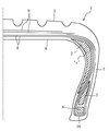
以下、本発明の実施形態について図1ないし図9に基づいて説明する。図1は、本実施形態のタイヤ1を示す子午線断面図である。タイヤ1は、いわゆるサイド補強型のランフラットタイヤであり、タイヤ1の両サイド部のカーカス4とインナーライナ8との間にそれぞれ、断面略三日月状をなすサイド補強ゴム層2が配設される。図1において、符号3はトレッド、符号5はサイドウォール、符号6はピードコア、符号7はビードフィラ、符号9はベルト、符号16はキャンバスチェーファである。
【0022】
図2は、図1の“a”部を示す詳細断面図であり、サイド補強ゴム層2は、複数周巻回された連続ゴムリボン2aが積層されてなる。
【0023】
図3〜図6は、各工程における形成途中の生タイヤの状態を示す子午線断面図である。第一の工程では、図3(a)に示すように、拡縮径可能なカーカスバンドドラム14の周上に、二枚のカーカスプライを一枚ずつ貼り付けて円筒状のカーカス部材4Aを形成し、次いで、図3(b)に示すように、ビードフィラゴム7Aがプリセットされた左右ビードコア6を把持する一対のビード把持リング30Aの半径方向内側に、カーカス部材4Aを貼り付けたカーカスバンドドラム14を挿入し、そして、図3(c)に示すように、カーカスバンドドラム14を拡径させてカーカス部材4Aをビードコア6の内周面に全周にわたって密着させ、次に、図4(a)に示すように、カーカスバンドドラム14を縮径してカーカス部材4Aの半径方向内側位置から退出させる。
【0024】
第二の工程では、図4(b)に示すように、同一軸線上を互いに離隔接近可能に設けられた一対の、拡縮可能でかつ直径が軸方向に沿って実質上変化しない第一のドラム11a、11bの周上に、サイド補強ゴム2Aをそれぞれ貼り付ける。
【0025】
第三の工程では、図4(c)に示すように、サイド補強ゴム2Aを貼り付けた第一のドラム11a、11bを、ビード把持リング30Aで把持された円筒状カーカス部材4Aの半径方向に挿入し、次いで、図5(a)に示すように、第一のドラム11a、11bを拡径してサイド補強ゴム2Aをカーカス部材4Aの内周面に圧着して第一の筒状部材13を形成し、続いて、図5(b)に示すように、第一のドラム11a、11bを縮径したあと、第一のドラム11a、11bを第一の筒状部材13の半径方向内側位置から退出させる。
【0026】
第四の工程では、図5(c)に示すように、拡縮可能でかつ直径が軸方向に沿って実質上変化しない第二のドラム12の周上に、インナーライナ8A、キャンバスチェーファ部材16Aをこの順に貼り付けて第二の筒状部材15を形成する。
【0027】
第五の工程では、図6(a)に示すように、第二の筒状部材15を貼り付けた第二のドラム12を、第一の筒状部材13の半径方向内側に挿入し、図6(b)に示すように、第二のドラム12を拡径して、第二の筒状部材15を、第一の筒状部材13の半径方向内側に圧着し、第三の筒状部材17を形成したあと、第二のドラムを第三の筒状部材17の半径方向内側位置から退出させる。
【0028】
第六の工程では、図6(c)に示すように、第三の筒状部材17の半径方向内側に、シェーピングドラム40を挿入し、このあと、図示しないが、従来の方法に従って、第三の筒状部材17の両ビードコア6間に延在する部分をトロイダル状に変形させたあと、ベルト部材、およびトレッドゴムを貼り付けて生タイヤを形成し、この生タイヤをモールドに装着して加硫成形してタイヤを完成する。
【0029】
ここで、前記第三の工程において、第一のドラム11a、11bを拡径させて、サイド補強ゴム2Aをカーカス部材4Aの内周面に圧着するに際し、これらの部材の間にエア溜まりやしわが発生しないよう、対をなす第一ドラム11a、11bの拡径動作および相互の接近動作、さらには、両ビード把持リングの接近動作をすべて同期させる必要がある。この同期は、以下のようにして行うことが好ましい。
【0030】
図7(a)は、サイド補強ゴム2Aが、カーカス部材4Aの内周面に当接し始めた状態において示す、サイド補強ゴム2Aの子午線断面図であり、図7(b)は、サイド補強ゴム2Aとカーカス部材4Aの内周面との圧着が完了した状態において示す、サイド補強ゴム2Aの子午線断面図である。図において、点P1は、サイド補強ゴム2Aの半径方向最外側の点、点P2は幅方向最内側の点、P3幅方向最外側の点を表わし、P1とP2との半径方向距離、すなわちサイド補強ゴム2Aの厚さをr1、P1とP2との幅をd2、P1からP2までのペリフェリ長をs1、P1からP3までのペリフェリ長をs2‘で表わす。このとき、P2からP1を経由してP3に至るまでのペリフェリ長s2は、(s1+s2’)で表わされる。
【0031】
ここで、図7(a)における、両側のサイド補強ゴム2Aの点P1間に延在するたカーカス部材4Aの総延長はD1であり、一方、図7(b)における、P1間に延在するたカーカス部材4Aの総延長は、((D2−2xd1)+2xs1)となるが、これらの総延長は、カーカス部材にはしわが発生しないためには等しくなければならず、したがって、式(1)を導くことができ、また、左右のビード把持リング30A間の間隔、L1とL2との関係についても、同様の考えに基づいて、式(2)を導くことができる。
D1−D2=2x(s1−d1) (1)
L1−L2=2x(s2−d2) (2)
【0032】
以上、式(1)および(2)より、サイド補強ゴム2Aとカーカス部材4Aとの間にエア溜まりやしわを発生させないためには、点P1がカーカス部材内周面に当接した時点から第一のドラム11a、11bを(2xr1)だけ拡径するまでの間に、これらの第一ドラム11a、11bの相互の間隔を(2x(s1−d1))だけ狭め、前記両ビード把持リング30Aの相互の間隔を(2x(s2−d2))だけ狭めて、第一のドラム11a、11bおよびビード把持リング30Aの動作を同期させることが好ましい。
【0033】
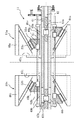
図8は、以上のタイヤの製造方法に用いられる成形システムの例を示す配置図である。成型システム10は、回転駆動装置11Aにより回転され、矢印L、Rの方向に往復変位する第一のドラム11a、11b、回転駆動装置12Aにより回転され、矢印L、Rの方向に往復変位する第二のドラム12、回転駆動装置14Aにより回転され、矢印L、Rの方向に往復変位するカーカスバンドドラム14、ビード把持リング30Aを有し、ビードコア6、円筒状カーカス部材4A、第一〜第三の筒状部材13、15,17を矢印F、Bの方向に搬送するトランスファー台車30、および、トランスファー台車30から第三の筒状部材17を受け取りこの中央部をトロイダル状に膨出させるシェーピングドラム40を具える。
【0034】
また、第一のドラム11a、11bに、サイド補強ゴム2Aを貼り付けるサイド補強ゴム貼り付け装置22が設けられ、第二のドラム12に、インナーライナゴム8A、キャンバスチェーファ部材16Aおよびスキージゴム(図示せず)をそれぞれ貼り付ける、インナーライナゴム貼り付け装置18、キャンバスチェーファ貼り付け装置19およびスキージゴム貼り付け装置20が設けられ、また、カーカスバンドドラム14に、カーカス部材の二枚のプライをそれぞれ貼り付ける第一および第二のカーカス部材貼り付け装置24、26と、スキージゴム(図示せず)を貼り付けるスキージゴム貼り付け装置28とが設けられる。
【0035】
ここで、カーカスバンドドラム14と第二のドラム12とは、ともに拡縮可能で、直径が幅方向に沿って実質上一定とされた一般的なタイヤ用ドラムを用いている(例えば、特開平5−305682号公報等に記載の装置)。また、第一のドラム11a、11bは、拡縮可能で、直径が幅方向に沿って実質上一定になり、あわせて、両方のドラム11a、11bが所定の対称面を中心に互いに離隔接近するよう設けられる。図9は、第一のドラム11a、11bの構成例を、その軸心を通る断面において示す断面図である。
【0036】
第一のドラム11a、11bはそれぞれ、回転駆動装置11Aによって回転される主軸41上を軸方向に往復変位するスライダ45a、45bと、周方向に隣接し合い、スライダ45a、45bの、主軸41に直角な面47a、47bに沿って半径方向内外に拡縮する複数のセグメント46a、46bと、スライダ45a、45bの周面49a、49b上を軸方向に往復変位可能に設けられ錐面部分にセグメント46a、46bを案内する直動ガイド53a、53bを設けたコーン体48a、48bとを具え、主軸41に設けられた中空部には、軸の左右でリードが逆向きのネジ部を有するドラム移動用ボールネジ42と、ボールネジ42の左右のそれぞれのネジ部に螺合して互いに左右反対側に向かって変位するネジブロック43a、43bとが設けられ、主軸41の半径方向外側には、スライダ45a、45bに軸支されたて図示しない回転駆動装置により回転される、軸の左右でリードが逆向きのネジ部を有するドラム拡縮用ボールネジ51と、ボールネジ51の左右のそれぞれのネジ部に螺合して互いに左右反対側に向かって変位するネジブロック52a、52bとが設けられる。
【0037】
このように構成されたドラム11a、11bにおいて、ネジブロック43a、43bとネジブロック52a、52bとが同期して変位するよう、ドラム移動用ボールネジ42とドラム拡縮用ボールネジ51とを回転することにより、セグメント46a、46bの拡縮を伴うことなく、ドラム11a、11b全体を相対離隔接近させることができ、また、ドラム拡縮用ボールネジ51だけを回転することにより、セグメント46a、46bの拡縮だけを行わせることができる。
【0038】
なお、図9において、縦横の中心線で区切られた四つの領域にそれぞれ示されるドラムの状態は、左上の領域では、セグメント46bが半径方向外側に拡径しかつ軸方向外側に変位した状態、左下の領域では、セグメント46bが半径方向内側に縮径しかつ軸方向外側に変位した状態、右上の領域では、セグメント46aが半径方向外側に拡径しかつ軸方向内側に変位した状態、右下の領域では、セグメント46aが半径方向内側に縮径しかつ軸方向外側に変位した状態を表わす。
【0039】
【発明の効果】
以上述べたところから明らかなように、本発明によれば、サイド補強ゴム2Aを貼り付けるための第一のドラム11a、11bは、直径が軸方向に沿って実質上変化しないよう構成されているので、最小の設備よりなる多サイズ混流生産システムで生産することができ、また、前記第三の工程において、カーカス部材4A内周面がサイド補強ゴム2A外周面にぴったり圧着されるよう、第一のドラムの拡径動作、第一のドラム11a、11bの相互の接近動作、および、ビード把持リング30Aの相互の接近動作を同期させるので、これらの部材の間にエア溜まりやしわが発生するのを防止することができる。
【図面の簡単な説明】
【図1】 本発明に係る実施形態のタイヤを示す子午線断面図である。
【図2】 図1の“a”部を示す詳細断面図である。
【図3】 形成途中の生タイヤの状態を示す子午線断面図である。
【図4】 図3に続く工程における生タイヤの状態を示す子午線断面図である。
【図5】 図4に続く工程における生タイヤの状態を示す子午線断面図である。
【図6】 図5に続く工程における生タイヤの状態を示す子午線断面図である。
【図7】 第一のドラムとビード把持リングとの同期作動を説明する、サイド補強ゴムの子午線断面図である。
【図8】 成形システムの例を示す配置図である。
【図9】 第一のドラムの構成例を示す断面図である。
【図10】 従来のサイド補強型のランフラットタイヤを示す子午線断面図である。
【図11】 従来のランフラットタイヤ用の生タイヤを成型途中の状態で示す断面図である。
【符号の説明】
1 タイヤ
2 サイド補強ゴム層
2a 連続ゴムリボン
2A サイド補強ゴム
3 トレッド
4 カーカス
4A カーカス部材
5 サイドウォール
6 ピードコア
7 ビードフィラ
7A ビードフィラゴム
8 インナーライナ
8A インナーライナゴム
9 ベルト
10 成型システム
11A 回転駆動装置
11a、11b 第一のドラム
12 第二のドラム
12A 回転駆動装置
13 第一の筒状部材
14 カーカスバンドドラム
14A 回転駆動装置
15 第二の筒状部材
16 キャンバスチェーファ
16A キャンバスチェーファ部材
17 第三の筒状部材
18 インナーライナゴム貼り付け装置
19 キャンバスチェーファ貼り付け装置
20 スキージゴム貼り付け装置
24、26 カーカス部材貼り付け装置
28 スキージゴム貼り付け装置
30 トランスファー台車
30A ビード把持リング
40 シェーピングドラム
41 主軸
42 ドラム移動用ボールネジ42
43a、43b ネジブロック
45a、45b スライダ
46a、46b セグメント
47a、47b スライダの、主軸に直角な面
48a、48b コーン体
49a、49b スライダの周面
51 ドラム拡縮用ボールネジ
52a、52b ネジブロック
53a、53b 直動ガイド[0001]
BACKGROUND OF THE INVENTION
The present invention relates to a method of manufacturing a run-flat tire in which a side reinforcing rubber layer having a substantially crescent-shaped cross section is interposed between a carcass and an inner liner at a side portion of a tire, and in particular, multi-size mixed flow production with minimum equipment. The present invention relates to a tire manufacturing method that can be produced by a system and that does not generate air accumulation or wrinkles between a carcass inner peripheral surface and a side reinforcing layer, and a tire.
[0002]
[Prior art]
As a run-flat tire having a radial structure that enables the vehicle to run even at the time of banking or the like, for example, as shown in FIG. 10, a side
[0003]
In FIG. 10,
[0004]
Here, as one method for producing a general tire for a radial tire, for example, an inner liner rubber is wound around a band drum whose diameter does not substantially change along the axial direction, and a carcass member and a bead core are set. A method is known in which this is folded to attach a side wall rubber, and then transferred to a shaving drum to set a belt member, a tread rubber and the like to form a green tire.
[0005]
When forming a raw tire for the run-
[0006]
In a normal radial tire, the surface of the band drum may be flat because there is no
[0007]
[Patent Document 1]
Japanese Patent Laid-Open No. 003-071950
[Problems to be solved by the invention]
However, there are various widths and thicknesses of the
[0009]
For this reason, when trying to produce such a tire in a multi-size mixed flow production system, the width, volume, shape, and shape of the
[0010]
Further, the groove portion of the
[0011]
The present invention has been made in view of such a problem, and can be produced by a multi-size mixed flow production system having the minimum equipment, and an air pool is formed between the inner circumferential surface of the carcass and the side reinforcing layer. It is an object to provide a tire manufacturing method and a tire that do not generate wrinkles and wrinkles.
[0012]
[Means for Solving the Problems]
In order to achieve the above object, the present invention has been made, and the gist configuration and operation thereof will be described below.
[0013]
The method for manufacturing a tire according to claim 1 includes a carcass extending in a toroidal shape between both bead cores, and an inner liner disposed on the inner peripheral side of the carcass, and the carcass and inner liner of the side portion of the tire. In the method of manufacturing a tire having a side reinforcing rubber layer having a substantially crescent-shaped cross section between
A first step of gripping a pair of bead cores that are closely attached to the outer peripheral surface of the carcass member formed in a cylindrical shape and spaced apart from each other in the axial direction with a bead grip ring;
A second step of attaching side reinforcing rubbers to the circumference of a pair of first and second drums that are provided on the same axis so as to be spaced apart from each other and that can be expanded and contracted and whose diameter does not substantially change along the axial direction. When,
The first drum is inserted radially inward of the carcass member and then expanded in diameter, and a side reinforcing rubber is pressure-bonded to the inner peripheral surface of the carcass member to form a first tubular member, and then the first drum A third step of retracting the drum from the radially inner side of the first tubular member;
Fourth step of forming a second cylindrical member by pasting one or more members including an inner liner rubber on the circumference of the second drum that can be expanded and contracted and whose diameter does not substantially change along the axial direction. When,
The second drum with the second cylindrical member attached is inserted into the first cylindrical member in the radial direction and then expanded in diameter, and the second cylindrical member is expanded with the first cylindrical member. A fifth step of forming a third tubular member by pressure bonding to the inner peripheral surface of the member;
After deforming the portion extending between the bead cores of the third cylindrical member into a toroidal shape, a belt member and a tread rubber are pasted to form a raw tire, and the raw tire is loaded into a mold. A sixth step of vulcanization molding,
In the third step, the diameter expansion operation of the first drum, the close movement operation of the first drum, and the bead grip ring so that the inner peripheral surface of the carcass member is tightly pressed against the outer peripheral surface of the side reinforcing rubber. Are performed in synchronization with each other.
[0014]
According to the tire manufacturing method according to the present invention, the first drum for attaching the side reinforcing rubber is configured such that the diameter does not substantially change along the axial direction, and thus includes the minimum equipment. It can be produced by a multi-size mixed flow production system, and in the third step, the diameter expansion operation of the first drum is performed so that the inner peripheral surface of the carcass member is closely pressed against the outer peripheral surface of the side reinforcing rubber. Synchronizing the close movement of the drums and the close movement of the bead gripping ring tightly presses the outer circumferential surface of the side reinforcing rubber to the inner circumferential surface of the carcass member. It is possible to prevent the occurrence of wrinkles.
[0015]
The tire manufacturing method according to
[0016]
According to this tire manufacturing method, as described above, the operations of the first drum and the bead grip ring are synchronized, and the outer peripheral surface of the side reinforcing rubber and the inner peripheral surface of the carcass member are pressure-bonded. Can be more reliably prevented.
[0017]
According to a third aspect of the present invention, in the tire manufacturing method according to the first or second aspect, the unvulcanized continuous rubber ribbon is attached to the first drum when the side reinforcing rubber is attached in the second step. A method of manufacturing a tire that is wound around the circumference of the tire multiple times.
[0018]
According to this tire manufacturing method, when the side reinforcing rubber is pasted, the unvulcanized continuous rubber ribbon is wound around the circumference of the first drum a plurality of times, so that a plurality of sizes of tires are multi-sized. When producing in a mixed flow production system, various side-reinforced rubber long members having different cross-sectional shapes are prepared in advance, and these are switched in accordance with the molding order, and a single size unvulcanized continuous rubber ribbon is laminated or laminated. By changing the number of times, it can be adapted to other types of sizes, enabling efficient production.
[0021]
DETAILED DESCRIPTION OF THE INVENTION
Hereinafter, embodiments of the present invention will be described with reference to FIGS. FIG. 1 is a meridian cross-sectional view showing a tire 1 of the present embodiment. The tire 1 is a so-called side-reinforced run-flat tire, and a side reinforcing
[0022]
FIG. 2 is a detailed cross-sectional view showing the “a” portion of FIG. 1, and the side reinforcing
[0023]
3 to 6 are meridian cross-sectional views showing the state of the green tire being formed in each step. In the first step, as shown in FIG. 3A, a
[0024]
In the second step, as shown in FIG. 4 (b), a pair of first drums which are provided on the same axis so as to be spaced apart from each other and which can be expanded and contracted and whose diameter does not substantially change along the axial direction.
[0025]
In the third step, as shown in FIG. 4C, the
[0026]
In the fourth step, as shown in FIG. 5C, the
[0027]
In the fifth step, as shown in FIG. 6 (a), the
[0028]
In the sixth step, as shown in FIG. 6 (c), the shaping
[0029]
Here, in the third step, when the diameters of the
[0030]
FIG. 7A is a meridian cross-sectional view of the
[0031]
Extending Here, in FIG. 7 (a), the total length of the
D 1 -D 2 = 2x (s 1 -d 1 ) (1)
L 1 −L 2 = 2x (s 2 −d 2 ) (2)
[0032]
Above, the equation (1) and (2), in order to the side not reinforced by generating air accumulation and wrinkles between the
[0033]
FIG. 8 is a layout diagram showing an example of a molding system used in the above tire manufacturing method. The
[0034]
Further, a side reinforcing
[0035]
Here, each of the
[0036]
The
[0037]
By rotating the drum moving
[0038]
In FIG. 9, the state of the drum shown in each of the four regions divided by the vertical and horizontal center lines is the state in which the
[0039]
【The invention's effect】
As is apparent from the above description, according to the present invention, the
[Brief description of the drawings]
FIG. 1 is a meridian cross-sectional view showing a tire according to an embodiment of the present invention.
FIG. 2 is a detailed sectional view showing an “a” portion of FIG. 1;
FIG. 3 is a meridian cross-sectional view showing a state of a green tire being formed.
4 is a meridian cross-sectional view showing a state of a raw tire in a process following FIG. 3. FIG.
FIG. 5 is a meridian cross-sectional view showing a state of a raw tire in a process following FIG.
6 is a meridian cross-sectional view showing a state of a raw tire in a process following FIG.
FIG. 7 is a meridian cross-sectional view of a side reinforcing rubber for explaining the synchronous operation of the first drum and the bead gripping ring.
FIG. 8 is a layout view showing an example of a molding system.
FIG. 9 is a cross-sectional view showing a configuration example of a first drum.
FIG. 10 is a meridian cross-sectional view showing a conventional side-reinforced run-flat tire.
FIG. 11 is a cross-sectional view showing a green tire for a conventional run-flat tire in the middle of molding.
[Explanation of symbols]
DESCRIPTION OF SYMBOLS 1
43a,
Claims (3)
円筒状に形成されたカーカス部材の外周面に全周にわたって密着し軸方向に互いに離隔して配置された一対のビードコアを、ビード把持リングでそれぞれ把持する第一の工程と、
同一軸線上を互いに離隔接近可能に設けられた一対の、拡縮可能でかつ直径が軸方向に沿って実質上変化しない第一のドラムの周上に、サイド補強ゴムをそれぞれ貼り付ける第二の工程と、
前記第一のドラムを前記カーカス部材の半径方向内側に挿入したあと拡径し、サイド補強ゴムを前記カーカス部材の内周面に圧着して第一の筒状部材を形成し、次いで第一のドラムを第一の筒状部材の半径方向内側から退出させる第三の工程と、
拡縮可能でかつ直径が軸方向に沿って実質上変化しない第二のドラムの周上に、インナーライナゴムを含む一以上の部材を貼り付けて第二の筒状部材を形成する第四の工程と、
前記第二の筒状部材を貼り付けた前記第二のドラムを前記第一の筒状部材の半径方向内側に挿入したあと拡径し、前記第二の筒状部材を前記第一の筒状部材の内周面に圧着して第三の筒状部材を形成する第五の工程と、
第三の筒状部材の、両ビードコア間に延在する部分をトロイダル状に変形させたあと、ベルト部材、及びトレッドゴムを貼り付けて生タイヤを形成し、前記生タイヤをモールドに装填して加硫成形する第六の工程とを有し、
前記第三の工程において、カーカス部材の内周面がサイド補強ゴム外周面にぴったり圧着されるよう、第一のドラムの拡径動作、第一のドラムの相互の接近動作、および、ビード把持リングの相互の接近動作を同期させて行うタイヤの製造方法。A side reinforcing rubber having a substantially crescent-shaped cross section between the carcass and the inner liner on the side of the tire, comprising a carcass extending in a toroidal shape between both bead cores and an inner liner disposed on the inner peripheral side of the carcass. In the method of manufacturing a tire comprising a layer,
A first step of gripping a pair of bead cores that are closely attached to the outer peripheral surface of the carcass member formed in a cylindrical shape and spaced apart from each other in the axial direction with a bead grip ring;
A second step of attaching side reinforcing rubbers to the circumference of a pair of first and second drums that are provided on the same axis so as to be spaced apart from each other and that can be expanded and contracted and whose diameter does not substantially change along the axial direction. When,
The first drum is inserted radially inward of the carcass member and then expanded in diameter, and a side reinforcing rubber is pressure-bonded to the inner peripheral surface of the carcass member to form a first tubular member, and then the first drum A third step of retracting the drum from the radially inner side of the first tubular member;
Fourth step of forming a second cylindrical member by pasting one or more members including an inner liner rubber on the circumference of the second drum that can be expanded and contracted and whose diameter does not substantially change along the axial direction. When,
The second drum with the second cylindrical member attached is inserted into the first cylindrical member in the radial direction and then expanded in diameter, and the second cylindrical member is expanded with the first cylindrical member. A fifth step of forming a third tubular member by pressure bonding to the inner peripheral surface of the member;
After deforming the portion extending between the bead cores of the third cylindrical member into a toroidal shape, a belt member and a tread rubber are pasted to form a raw tire, and the raw tire is loaded into a mold. A sixth step of vulcanization molding,
In the third step, the diameter expansion operation of the first drum, the close movement operation of the first drum, and the bead grip ring so that the inner peripheral surface of the carcass member is tightly pressed against the outer peripheral surface of the side reinforcing rubber. Tire manufacturing method in which the mutual approaching operations are synchronized.
左右の第一のドラムを拡径するに際し、これらの拡径を左右のドラムで同期させるとともに、点P1がカーカス部材内周面に当接した時点から第一のドラムを(2xr1)だけ拡径するまでの間に、これらの第一ドラムの相互の間隔を(2x(s1−d1))だけ狭め、前記両ビード把持リングの相互の間隔を(2x(s2−d2))だけ狭めて、第一のドラムおよびビード把持リングの動作を同期させる請求項1に記載のタイヤの製造方法。In the third step, the radially outermost point in the meridian section of the side reinforcing rubber after the first drum diameter expansion is P 1 , the innermost point in the axial direction is P 2 , and the outermost point in the axial direction is P 3 , the radial distance between P 1 and P 2 is r 1 , the axial distance between P 1 and P 2 is d 1 , the axial distance between P 2 and P 3 is d 2 , and P 1 to P 2 when the periphery length up to P 3 periphery length from s 1, P 2 via the P 1 up to and s 2,
When expanding the diameters of the left and right first drums, the diameter expansion is synchronized between the left and right drums, and the first drum is only (2xr 1 ) from the point when the point P 1 abuts the inner circumferential surface of the carcass member. Until the diameter is expanded, the distance between the first drums is reduced by (2x (s 1 -d 1 )), and the distance between the bead gripping rings is (2x (s 2 -d 2 )). The tire manufacturing method according to claim 1, wherein the operations of the first drum and the bead gripping ring are synchronized with each other by narrowing.
Priority Applications (6)
| Application Number | Priority Date | Filing Date | Title |
|---|---|---|---|
| JP2003202989A JP4301883B2 (en) | 2003-07-29 | 2003-07-29 | Tire manufacturing method and tire |
| US10/566,165 US7520949B2 (en) | 2003-07-29 | 2004-07-14 | Tire manufacturing method and tire |
| AT04747512T ATE402808T1 (en) | 2003-07-29 | 2004-07-14 | TIRE MANUFACTURING PROCESS. |
| DE602004015465T DE602004015465D1 (en) | 2003-07-29 | 2004-07-14 | TIRE MANUFACTURING PROCESS. |
| PCT/JP2004/010046 WO2005009725A1 (en) | 2003-07-29 | 2004-07-14 | Tire producing method and tire |
| EP04747512A EP1650012B1 (en) | 2003-07-29 | 2004-07-14 | Method of producing a tire. |
Applications Claiming Priority (1)
| Application Number | Priority Date | Filing Date | Title |
|---|---|---|---|
| JP2003202989A JP4301883B2 (en) | 2003-07-29 | 2003-07-29 | Tire manufacturing method and tire |
Publications (2)
| Publication Number | Publication Date |
|---|---|
| JP2005047017A JP2005047017A (en) | 2005-02-24 |
| JP4301883B2 true JP4301883B2 (en) | 2009-07-22 |
Family
ID=34100618
Family Applications (1)
| Application Number | Title | Priority Date | Filing Date |
|---|---|---|---|
| JP2003202989A Expired - Fee Related JP4301883B2 (en) | 2003-07-29 | 2003-07-29 | Tire manufacturing method and tire |
Country Status (6)
| Country | Link |
|---|---|
| US (1) | US7520949B2 (en) |
| EP (1) | EP1650012B1 (en) |
| JP (1) | JP4301883B2 (en) |
| AT (1) | ATE402808T1 (en) |
| DE (1) | DE602004015465D1 (en) |
| WO (1) | WO2005009725A1 (en) |
Families Citing this family (8)
| Publication number | Priority date | Publication date | Assignee | Title |
|---|---|---|---|---|
| JP4402534B2 (en) * | 2004-07-21 | 2010-01-20 | 株式会社ブリヂストン | Tire molding apparatus and method of using the same |
| DE102006040413A1 (en) * | 2006-08-29 | 2008-03-06 | Continental Aktiengesellschaft | Method for building a green tire or a green tire carcass on a tire building drum |
| NL2004734C2 (en) * | 2010-05-18 | 2011-11-21 | Vmi Holland Bv | METHOD AND COMPOSITION FOR MANUFACTURING A GREEN BAND |
| DE102012014987B4 (en) | 2012-07-27 | 2020-10-15 | Harburg-Freudenberger Maschinenbau Gmbh | Turn-up device for tire sidewalls |
| DE102013103633A1 (en) * | 2013-04-11 | 2014-10-16 | Continental Reifen Deutschland Gmbh | Method and system for producing a carcass for a pneumatic vehicle tire |
| DE102013103629A1 (en) * | 2013-04-11 | 2014-10-16 | Continental Reifen Deutschland Gmbh | Method for producing a vehicle tire |
| JP5566504B1 (en) * | 2013-06-05 | 2014-08-06 | 株式会社ブリヂストン | Carcass band molding apparatus and carcass band molding method |
| JP6295812B2 (en) * | 2014-05-09 | 2018-03-20 | 横浜ゴム株式会社 | Method and apparatus for manufacturing run-flat tire |
Family Cites Families (4)
| Publication number | Priority date | Publication date | Assignee | Title |
|---|---|---|---|---|
| JPS62255205A (en) * | 1986-04-30 | 1987-11-07 | Bridgestone Corp | Pneumatic safety tire |
| WO2002060676A1 (en) * | 2001-01-31 | 2002-08-08 | Bridgestone Corporation | Tire manufacturing method |
| JP4603736B2 (en) | 2001-09-06 | 2010-12-22 | 株式会社ブリヂストン | Tire manufacturing method |
| US6769468B2 (en) | 2001-09-21 | 2004-08-03 | The Goodyear Tire & Rubber Company | Tire building drum having expandable center section and independently expandable bead lock assemblies in the end sections |
-
2003
- 2003-07-29 JP JP2003202989A patent/JP4301883B2/en not_active Expired - Fee Related
-
2004
- 2004-07-14 DE DE602004015465T patent/DE602004015465D1/en active Active
- 2004-07-14 US US10/566,165 patent/US7520949B2/en not_active Expired - Fee Related
- 2004-07-14 EP EP04747512A patent/EP1650012B1/en not_active Not-in-force
- 2004-07-14 WO PCT/JP2004/010046 patent/WO2005009725A1/en active IP Right Grant
- 2004-07-14 AT AT04747512T patent/ATE402808T1/en not_active IP Right Cessation
Also Published As
| Publication number | Publication date |
|---|---|
| WO2005009725A1 (en) | 2005-02-03 |
| EP1650012B1 (en) | 2008-07-30 |
| US7520949B2 (en) | 2009-04-21 |
| EP1650012A1 (en) | 2006-04-26 |
| EP1650012A4 (en) | 2006-10-25 |
| US20070187016A1 (en) | 2007-08-16 |
| JP2005047017A (en) | 2005-02-24 |
| DE602004015465D1 (en) | 2008-09-11 |
| ATE402808T1 (en) | 2008-08-15 |
Similar Documents
| Publication | Publication Date | Title |
|---|---|---|
| US7837816B2 (en) | Method and device for the construction of a radial tire | |
| US20100000662A1 (en) | Method for manufacturing green tire and apparatus for building green tire | |
| JP4777585B2 (en) | First stage creation drum for manufacturing run flat tires and method of using the same | |
| US7931768B2 (en) | Method and device for constructing a radial tire | |
| EP2923827B1 (en) | Method for manufacturing a motorcycle tire | |
| JP2003071950A (en) | Method for manufacturing tire | |
| CN103587134A (en) | Sleeveless tire building drum | |
| JP4301883B2 (en) | Tire manufacturing method and tire | |
| US20050279444A1 (en) | Tire building apparatus and assembly process | |
| EP2239130B1 (en) | Pneumatic tire manufacturing method, and pneumatic tire | |
| WO2021227927A1 (en) | Tire building drum | |
| JP5281671B2 (en) | Shaping former for run-flat tires | |
| JP4173711B2 (en) | Method for manufacturing run-flat tires | |
| JP4234922B2 (en) | Manufacturing method of pneumatic tire for motorcycle | |
| JP2010069663A (en) | Method and apparatus for manufacturing unvulcanized tire | |
| JP2002254529A (en) | Secondary molding method for tire | |
| EP0509094B1 (en) | Green tire building apparatus | |
| CN109501345A (en) | A kind of forming method of tyre building machine | |
| JP6450207B2 (en) | Pneumatic tire manufacturing method | |
| JP3124931B2 (en) | Manufacturing method of radial tire | |
| JP2005212278A (en) | Method for producing tire | |
| JP2009160850A (en) | Tire molding apparatus | |
| JPH09117970A (en) | Folding back bladder of tire molding drum | |
| JP2003146027A (en) | Bead core intermediate, and manufacturing method of and device for the same | |
| WO2004060642A2 (en) | Tire building apparatus and assembly process |
Legal Events
| Date | Code | Title | Description |
|---|---|---|---|
| A621 | Written request for application examination |
Free format text: JAPANESE INTERMEDIATE CODE: A621 Effective date: 20060615 |
|
| A131 | Notification of reasons for refusal |
Free format text: JAPANESE INTERMEDIATE CODE: A131 Effective date: 20090210 |
|
| A521 | Request for written amendment filed |
Free format text: JAPANESE INTERMEDIATE CODE: A523 Effective date: 20090305 |
|
| RD03 | Notification of appointment of power of attorney |
Free format text: JAPANESE INTERMEDIATE CODE: A7423 Effective date: 20090305 |
|
| TRDD | Decision of grant or rejection written | ||
| A01 | Written decision to grant a patent or to grant a registration (utility model) |
Free format text: JAPANESE INTERMEDIATE CODE: A01 Effective date: 20090331 |
|
| A01 | Written decision to grant a patent or to grant a registration (utility model) |
Free format text: JAPANESE INTERMEDIATE CODE: A01 |
|
| A61 | First payment of annual fees (during grant procedure) |
Free format text: JAPANESE INTERMEDIATE CODE: A61 Effective date: 20090421 |
|
| FPAY | Renewal fee payment (event date is renewal date of database) |
Free format text: PAYMENT UNTIL: 20120501 Year of fee payment: 3 |
|
| R150 | Certificate of patent or registration of utility model |
Free format text: JAPANESE INTERMEDIATE CODE: R150 |
|
| FPAY | Renewal fee payment (event date is renewal date of database) |
Free format text: PAYMENT UNTIL: 20130501 Year of fee payment: 4 |
|
| FPAY | Renewal fee payment (event date is renewal date of database) |
Free format text: PAYMENT UNTIL: 20140501 Year of fee payment: 5 |
|
| R250 | Receipt of annual fees |
Free format text: JAPANESE INTERMEDIATE CODE: R250 |
|
| R250 | Receipt of annual fees |
Free format text: JAPANESE INTERMEDIATE CODE: R250 |
|
| LAPS | Cancellation because of no payment of annual fees |