JP4558993B2 - Mounting structure of the support on the desk - Google Patents
Mounting structure of the support on the desk Download PDFInfo
- Publication number
- JP4558993B2 JP4558993B2 JP2001276121A JP2001276121A JP4558993B2 JP 4558993 B2 JP4558993 B2 JP 4558993B2 JP 2001276121 A JP2001276121 A JP 2001276121A JP 2001276121 A JP2001276121 A JP 2001276121A JP 4558993 B2 JP4558993 B2 JP 4558993B2
- Authority
- JP
- Japan
- Prior art keywords
- support
- desk
- sleeve
- top plate
- fitting
- Prior art date
- Legal status (The legal status is an assumption and is not a legal conclusion. Google has not performed a legal analysis and makes no representation as to the accuracy of the status listed.)
- Expired - Fee Related
Links
Images


Description
【0001】
【発明の属する技術分野】
本発明は、机上に、棚板やピンナップボード等のオプション部品を支持する支杆を、高さ調節可能として取り付ける、机上への支杆の取付構造に関する。
【0002】
【従来の技術】
従来、机上に、上述のようなオプション部品を取り付ける場合、そのオプション部品の種類や必要とする耐荷重性、及び周囲の情況等に対応するため、オプション部品を支持する支杆として、長さ等の異なる複数種類のものを用意しておくことがある。
【0003】
また、オプション部品の高さを調節しうるものとしては、例えば、特開平11−123109号公報に開示されているように、机の天板に、上方を向く下部板状体を固着し、それに、互いに上下方向に摺動しうるように嵌合した1対のレールを介して、上部板状体を上下動可能として装着し、さらに両レールの摺動を停止させる状態を設けたものがある。
【0004】
さらに、ハンガースタンド等の高さ調節のように、ねじ環を緩めることにより、可動側パイプを固定側パイプより自由に出し入れでき、ねじ環を締めつけることにより、両パイプをロックしうるようにしたものがある。
【0005】
【発明が解決しようとする課題】
しかし、長さ等の異なる複数の支杆を用意しておくのは、不使用部品の管理や収納が面倒であり、経済的にも好ましくなく、上記公報に記載されているものでは、レールやレールの摺動を停止させる装置等が大型かつ複雑化し、高価なものとなる。
【0006】
また、ねじ環を用いるものでは、互いに連結した左右1対の支杆を均等に上下動させることが難しく、しかも大きな荷重がかかると、ねじ環が緩んで、可動側パイプが不意に収縮するおそれがある。
【0007】
本発明は、従来の技術が有する上記の様な問題点に鑑み、オプション部品等を支持する支杆を、部品点数の少ない簡単な構造で、容易に高さ調節でき、しかも支杆を強力に支持しうるようにした体裁のよい机上への支杆の取付構造を提供することを目的としている。
【0008】
【課題を解決するための手段】
本発明によると、上記課題は、次のようにして解決される。
(1) 上下方向を向く支杆の外周に、複数の係合孔を、支杆の長手方向に所要の間隔をもって穿設するとともに、互いに向き合わせて合体させることにより、上端部に拡径フランジを備える上下方向を向くスリーブを形成するようにした1対のほぼ半円筒状のスリーブ分割片により、前記支杆を両側方より挟み、少なくともいずれか一方のスリーブ分割片の内面に、前記係合孔に選択的に係合しうる突部を設け、この突部を所望の係合孔に嵌合させて、両スリーブ分割片を、支杆とともに、机の上面に設けた下方を向く嵌合孔に上方より嵌合し、かつ前記拡径フランジを、前記嵌合孔の上端縁に当接させて、支杆を机上に起立状態で支持するようにする。
【0009】
(2) 上記(1)項において、1対のスリーブ分割片の対向面のいずれか一方に突起を、かつ他方に前記突起が嵌合する凹部を設ける。
【0010】
【発明の実施の形態】
図1〜図6は、本発明の一実施形態を示す。
机(1)は、天板(2)と、それを支持する天板支持体(3)とからなり、天板支持体(3)は、前後の端部に円筒状の垂直の脚(4)の上端部を溶接等により固着した前後方向を向く角管よりなる側部連結杆(5)(5)の中央部同士を、左右方向を向く中間連結杆(6)をもって連結したものよりなっている。
【0011】
左右の後脚(4)(4)の上端は上方に開口し、この後脚(4)(4)の上端から下端に至る中空部により、後述するオプション部品支持用の支持部材(14)における左右1対の支杆(15)(15)を嵌挿しうる嵌合孔(7)(7)が形成されている。
【0012】
各側部連結杆(5)の前後2個所には、ボルト挿通孔(8)が上下方向に貫通するように設けられており、また天板(2)の下面には、図2に実線で示すように、天板(2)を、その後部で嵌合孔(7)(7)の上端開口を覆う後方位置としたとき、各ボルト挿通孔(8)と整合するようにした4個の埋込みナット(9)と、図2に想像線で示すように、天板(2)を、その後端が嵌合孔(7)より前方に位置して、嵌合孔(7)の上端開口が露呈するようにした前方位置としたときに、各ボルト挿通孔(8)と整合するようにした4個の埋込みナット(10)とが設けられている。
【0013】
したがって、各ボルト挿通孔(8)に下方より挿通させたボルト(11)の上端を、前方の埋込みナット(9)に螺合することにより、天板(2)を、後方位置として天板支持体(3)に取り付けることができ、同じく、ボルト(11)の上端を、後方の埋込みナット(10)に螺合することにより、天板(2)を、前方位置として天板支持体(3)に取り付けることができ、もって、天板支持体(3)の後部と天板(2)との位置関係を、嵌合孔(7)の上端開口が天板(2)の後部により覆われた孔閉塞状態と、天板(2)の後端が嵌合孔(7)の上端開口より前方に位置し、嵌合孔(7)の上端開口が露呈する孔開放状態とに変更することができる。
図2及び図3に示すように、天板(2)の下面における両側前後部には、天板(2)を、前方位置と後方位置との間を前後方向に摺動しうるように案内するガイド部材(12)が設けられている。
【0014】
各ガイド部材(12)は、止めねじ(13)をもって天板(2)の下面に固着された取付片(12a)と、その外側端から垂下し、かつ各側部連結杆(5)の内側面に摺接する垂下片(12b)と、垂下片(12b)の下端より外側方に水平に折曲形成され、各側部連結杆(5)の下面に係合する外向折曲片(12c)とからなっている。
【0015】
各ガイド部材(12)の長さは、天板(2)が後方位置のとき、後端が中間連結杆(6)の前面または後脚(4)の前面に当接し、天板(12)が前方位置のとき、前端が前脚(4)の後面または中間連結杆(6)の後面に当接するように定めてある。
【0016】
このガイド部材(12)により、天板(2)は、ボルト(11)を外したときでも、天板支持体(3)から外れることはなく、前後に自由に摺動でき、しかも前方位置と後方位置とに位置決めされるので、ボルト(11)を所望の埋込みナット(9)(10)に容易に螺合することができる。
【0017】
図4〜図6は、天板(2)を前方位置として、オプション部品支持用の支持部材(14)における右方の支杆(15)を嵌合孔(7)に嵌合した状態を示している。
【0018】
図1に示すように、支持部材(14)は、上下方向を向く左右1対の支杆(15)(15)の上端部同士を、互いに平行な上下2本の横杆(16)(16)を多数の傾斜杆(17)をもって連結してなる横連結枠(18)をもって連結したものよりなり、この横連結枠(18)及び左右の支杆(15)(15)に、ピンナップボード(19)、トレー(20)係止用のブラケット(21)、クロススクリーン(22)等のオプション部品を適宜装着しうるようになっている。
【0019】
左右の支杆(15)(15)の対向面には、複数の縦長の係合孔(23)が、上下方向に等間隔をもってそれぞれ穿設されている。
【0020】
(24)(25)は、互いに向き合わせて合体させることにより、上端部に拡径フランジを備える上下方向を向くスリーブを形成するようにした1対のほぼ半円筒状のスリーブ分割片である。
【0021】
各スリーブ分割片(24)(25)は、上下方向を向く半円筒部(24a)(25a)の上端に、截頭円錘体を縦に2分割した形状のフランジ半部(25b)が形成され、互いに対向する両側部のいずれか一方に上下2個ずつの縦長の切欠き(26)(26)を、かつ他方に、上記各切欠き(26)(26)に嵌合する上下2個ずつの縦長の突起(27)(27)をそれぞれ突設したものよりなっている。
【0022】
一方のスリーブ分割片(25)の内面中央には、支杆(15)における2個の係合孔(23)(23)に嵌合しうる2個の突部(28)(28)が、係合孔(23)(23)の上下間隔と同一の上下間隔をもって設けられている。
【0023】
各支杆(15)は、一方のスリーブ分割片(25)の突部(28)(28)を、所望の係合孔(23)(23)に嵌合し、かつ両スリーブ分割片(24)(25)の突起(27)(27)を、対応する切欠き(26)(26)に嵌合させて、両スリーブ分割片(24)を、中央に支柱(15)を挟んで互いに円筒状となるように合体し、その状態で両スリーブ分割片(24)(25)を、支杆(15)とともに、後脚(4)の上端の嵌合孔(7)に嵌合し、フランジ半部(24b)(25b)の下端を、後脚(4)の上端面に当接させることにより、天板支持体(3)の後部に支持される。
【0024】
突部(28)(28)を嵌合する支杆(15)の係合孔(23)(23)を選択することにより、支杆(15)(15)の高さを段階的に調節することができ、また左右の支杆(15)(15)の等高の係合孔(23)(23)に、左右のスリーブ分割片(25)(25)の突部(28)(28)を嵌合させて、両スリーブ分割片(24)(25)を各支杆(15)に外嵌することにより、左右の支杆(15)(15)の高さ合わせを簡単に行なうことができる。
【0025】
【発明の効果】
請求項1記載の発明によると、一方のスリーブ分割片の突部を、支杆の所望の係合孔に係合させて、1対のスリーブ分割片により支杆を両側方から挟んで、それらを机の上面に設けた嵌合孔に上方より嵌入するという簡単な操作により、支杆を、机上に、段階的ではあるが所望の高さで、強力に、起立状態で支持することができる。
しかも、部品点数が少なく、構造が簡単で、ブラケット等の突出物のない美麗な外観を呈することができる。
【0026】
請求項2記載の発明によると、突起と凹部とを互いに嵌合させることにより、両スリーブ分割片が互いに位置決めされ、それらを嵌合孔に円滑に挿入することができる。
【図面の簡単な説明】
【図1】本発明の一実施形態と、それを用いて取り付けようとする机とオプション部品等とを、斜め後方より見た分解斜視図である。
【図2】同じく、机の上部の一部破断側面図である。
【図3】図2のIII−III線に沿う拡大縦断正面図である。
【図4】天板を前方位置とし、かつ後脚に支持部材を嵌合したときの後脚上部の拡大側面図である。
【図5】図4のV−V線に沿う縦断面図である。
【図6】支持部材の取付部分の分解斜視図である。
【符号の説明】
(1)机
(2)天板
(3)天板支持体
(4)脚
(5)側部連結杆
(6)中間連結杆
(7)嵌合孔
(8)ボルト挿通孔
(9)(10)埋込みナット
(11)ボルト
(12)ガイド部材
(12a)取付片
(12b)垂下片
(12c)外向折曲片
(13)止めねじ
(14)支持部材
(15)支杆
(16)横杆
(17)傾斜杆
(18)横連結杆
(19)ピンナップボード
(20)トレー
(21)ブラケット
(22)クロススクリーン
(23)係合孔
(24)(25)スリーブ分割片
(24a)(25a)半円筒部
(24b)(25b)フランジ半部
(26)切欠き
(27)突起
(28)突部[0001]
BACKGROUND OF THE INVENTION
The present invention relates to a mounting structure for a support on a desk, on which a support for supporting optional parts such as a shelf board and a pinup board is mounted on a desk so that the height can be adjusted.
[0002]
[Prior art]
Conventionally, when mounting optional parts such as those described above on a desk, the length, etc., can be used as a support to support the optional parts in order to cope with the type of optional parts, the required load resistance, and the surrounding conditions. There may be a plurality of different types prepared.
[0003]
In addition, for example, as disclosed in Japanese Patent Application Laid-Open No. 11-123109, a lower plate-like body facing upward is fixed to a top plate of a desk as an option component height can be adjusted. In some cases, the upper plate-like body is mounted so as to be movable up and down via a pair of rails fitted so as to be slidable in the vertical direction, and a state in which sliding of both rails is stopped is provided. .
[0004]
Furthermore, by adjusting the height of a hanger stand, etc., loosening the screw ring allows the movable side pipe to be taken in and out freely from the fixed side pipe, and by tightening the screw ring, both pipes can be locked. There is.
[0005]
[Problems to be solved by the invention]
However, preparing a plurality of supports having different lengths is troublesome in management and storage of unused parts, which is not economically preferable. A device for stopping the sliding of the rail becomes large, complicated, and expensive.
[0006]
In addition, in the case of using a screw ring, it is difficult to move the pair of left and right supports connected to each other evenly, and when a large load is applied, the screw ring may loosen and the movable side pipe may contract unexpectedly. There is.
[0007]
In view of the above-mentioned problems of the conventional technology, the present invention can easily adjust the height of a support for supporting optional parts and the like with a simple structure with a small number of parts, and further strengthens the support. An object of the present invention is to provide a structure for mounting a support on a desk with good appearance that can be supported.
[0008]
[Means for Solving the Problems]
According to the present invention, the above problem is solved as follows.
(1) A plurality of engagement holes are formed in the longitudinal direction of the support in the vertical direction at a predetermined interval in the longitudinal direction of the support, and the diameter-enlarged flange is formed at the upper end portion by combining them with each other. A pair of substantially semi-cylindrical sleeve split pieces that form a vertically-facing sleeve including the support rods sandwiched from both sides, and the inner surface of at least one of the sleeve split pieces engages the engagement Protrusions that can be selectively engaged with the holes are provided, and the protrusions are fitted into the desired engagement holes, and both sleeve split pieces are fitted together with the support so as to face downward on the top surface of the desk. The hole is fitted into the hole from above and the diameter-enlarged flange is brought into contact with the upper end edge of the fitting hole so that the support is supported upright on the desk.
[0009]
(2) In the above item (1), a protrusion is provided on one of the opposing surfaces of the pair of sleeve split pieces, and a recess is provided on the other to which the protrusion is fitted.
[0010]
DETAILED DESCRIPTION OF THE INVENTION
1 to 6 show an embodiment of the present invention.
The desk (1) is composed of a top plate (2) and a top plate support (3) that supports the top plate (3), and the top plate support (3) has cylindrical vertical legs (4 ) And the middle part of side connection rods (5) and (5) made of square tubes facing in the front-rear direction, which are fixed by welding or the like, with intermediate connection rods (6) facing in the left-right direction. ing.
[0011]
The upper ends of the left and right rear legs (4) and (4) are opened upward, and the hollow parts extending from the upper ends to the lower ends of the rear legs (4) and (4) are used in a support member (14) for supporting optional parts described later. Fitting holes (7) and (7) into which a pair of left and right supports (15) and (15) can be inserted are formed.
[0012]
Bolt insertion holes (8) are provided at two positions in the front and rear of each side connecting rod (5) so as to penetrate in the vertical direction, and the bottom surface of the top plate (2) is shown by a solid line in FIG. As shown in the figure, when the top plate (2) is set to a rear position covering the upper end openings of the fitting holes (7) and (7) at the rear part, four bolts adapted to be aligned with each bolt insertion hole (8) As shown by an imaginary line in FIG. 2, the embedded nut (9), the top plate (2), the rear end thereof is positioned in front of the fitting hole (7), and the upper end opening of the fitting hole (7) is Four embedded nuts (10) are provided so as to align with the bolt insertion holes (8) when the front position is exposed.
[0013]
Therefore, the top plate (2) can be supported as a rear position by screwing the upper end of the bolt (11) inserted from below into each bolt insertion hole (8) to the front embedded nut (9). It can be attached to the body (3). Similarly, by screwing the upper end of the bolt (11) to the rear embedded nut (10), the top plate (2) can be used as the front position. Therefore, the upper end opening of the fitting hole (7) is covered by the rear part of the top plate (2), with respect to the positional relationship between the rear part of the top plate support (3) and the top plate (2). Change to a hole open state where the rear end of the top plate (2) is located in front of the upper end opening of the fitting hole (7) and the upper end opening of the fitting hole (7) is exposed. Can do.
As shown in FIG. 2 and FIG. 3, the top plate (2) is guided to the front and rear portions of the lower surface of the top plate (2) so that it can slide between the front position and the rear position in the front-rear direction. A guide member (12) is provided.
[0014]
Each guide member (12) has a mounting screw (12a) fixed to the lower surface of the top plate (2) with a set screw (13), and is suspended from the outer end of the guide member (12). A hanging piece (12b) that is in sliding contact with the side surface, and an outward bent piece (12c) that is bent horizontally outward from the lower end of the hanging piece (12b) and engages the lower surface of each side connecting rod (5). It is made up of.
[0015]
The length of each guide member (12) is such that when the top plate (2) is in the rear position, the rear end abuts against the front surface of the intermediate connecting rod (6) or the front surface of the rear leg (4). When the is in the forward position, the front end is set to contact the rear surface of the front leg (4) or the rear surface of the intermediate coupling rod (6).
[0016]
The guide member (12) allows the top plate (2) to slide freely back and forth without being detached from the top plate support (3) even when the bolt (11) is removed. Since it is positioned at the rear position, the bolt (11) can be easily screwed into the desired embedded nut (9) (10).
[0017]
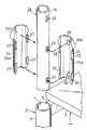
4 to 6 show the state in which the right support (15) of the support member (14) for supporting optional parts is fitted into the fitting hole (7) with the top plate (2) as the front position. ing.
[0018]
As shown in FIG. 1, the support member (14) has two upper and lower horizontal supports (16) (16) (16) (16) parallel to each other at the upper ends of a pair of left and right supports (15) and (15) facing upward and downward. ) Are connected with a horizontal connecting frame (18) formed by connecting a plurality of inclined rods (17), and the pinup board (18) is connected to the horizontal connecting frame (18) and the left and right supports (15) (15). 19) Optional parts such as a bracket (21) for locking the tray (20) and a cross screen (22) can be appropriately mounted.
[0019]
A plurality of vertically long engagement holes (23) are formed at equal intervals in the vertical direction on the opposing surfaces of the left and right supports (15) and (15).
[0020]
(24) and (25) are a pair of substantially semi-cylindrical sleeve division pieces which are formed so as to form a vertically oriented sleeve having a diameter-enlarged flange at the upper end portion by being opposed to each other.
[0021]
Each sleeve split piece (24) (25) is formed with a flange half (25b) in the shape of a vertically divided half truncated cone at the upper end of the semi-cylindrical part (24a) (25a) facing vertically The upper and lower vertical notches (26) and (26) are arranged on either one of the opposite side portions, and the upper and lower portions are fitted on the other notches (26) and (26) on the other side. Each of the vertically long projections (27) and (27) is formed by projecting.
[0022]
At the center of the inner surface of one sleeve segment (25), there are two protrusions (28) and (28) that can be fitted in the two engagement holes (23) and (23) of the support (15). The engaging holes (23) and (23) are provided with the same vertical interval as the vertical interval.
[0023]
Each support (15) is fitted with the projections (28) (28) of one sleeve split piece (25) in desired engagement holes (23) (23), and both sleeve split pieces (24 ) (25) projections (27) and (27) are fitted into the corresponding notches (26) and (26), and both sleeve split pieces (24) are cylindrical with each other with the column (15) in the middle. In this state, the sleeve divided pieces (24) and (25) are fitted together with the support (15) into the fitting hole (7) at the upper end of the rear leg (4), and the flange The lower ends of the half portions (24b) and (25b) are brought into contact with the upper end surfaces of the rear legs (4) to be supported by the rear portion of the top plate support (3).
[0024]
By selecting the engagement hole (23) (23) of the support (15) that fits the protrusion (28) (28), the height of the support (15) (15) is adjusted stepwise. The left and right sleeve split pieces (25) (25) and the protrusions (28) (28) By fitting the two sleeve segments (24) and (25) to the respective supports (15), the left and right supports (15) and (15) can be easily adjusted in height. it can.
[0025]
【The invention's effect】
According to the first aspect of the present invention, the protrusions of one of the sleeve divided pieces are engaged with the desired engagement holes of the support, and the support is sandwiched from both sides by the pair of sleeve divided pieces. The support can be supported on the desk in a stepped but powerful manner in a standing state by a simple operation of fitting from above into a fitting hole provided on the top surface of the desk. .
In addition, the number of parts is small, the structure is simple, and a beautiful appearance without protrusions such as brackets can be exhibited.
[0026]
According to the second aspect of the present invention, by fitting the protrusion and the concave portion with each other, the sleeve divided pieces are positioned with respect to each other, and can be smoothly inserted into the fitting hole.
[Brief description of the drawings]
FIG. 1 is an exploded perspective view of an embodiment of the present invention, a desk to be mounted using the embodiment, an optional component, and the like as viewed obliquely from the rear.
FIG. 2 is a partially broken side view of the upper part of the desk.
FIG. 3 is an enlarged longitudinal front view taken along line III-III in FIG.
FIG. 4 is an enlarged side view of the upper part of the rear leg when the top plate is at the front position and the support member is fitted to the rear leg.
FIG. 5 is a longitudinal sectional view taken along line VV in FIG. 4;
FIG. 6 is an exploded perspective view of a mounting portion of the support member.
[Explanation of symbols]
(1) Desk
(2) Top plate
(3) Top plate support
(4) Leg
(5) Side connection rod
(6) Intermediate connection rod
(7) Mating hole
(8) Bolt insertion hole
(9) (10) Embedded nut
(11) Bolt
(12) Guide member
(12a) Mounting piece
(12b) Hanging piece
(12c) Outward bending piece
(13) Set screw
(14) Support member
(15) Support
(16) Yokohama
(17) Inclined bowl
(18) Horizontal connection
(19) Pinup board
(20) Tray
(21) Bracket
(22) Cross screen
(23) Engagement hole
(24) (25) Sleeve split piece
(24a) (25a) Semi-cylindrical part
(24b) (25b) Half flange
(26) Notch
(27) Protrusion
(28) Projection
Claims (2)
Priority Applications (1)
| Application Number | Priority Date | Filing Date | Title |
|---|---|---|---|
| JP2001276121A JP4558993B2 (en) | 2001-09-12 | 2001-09-12 | Mounting structure of the support on the desk |
Applications Claiming Priority (1)
| Application Number | Priority Date | Filing Date | Title |
|---|---|---|---|
| JP2001276121A JP4558993B2 (en) | 2001-09-12 | 2001-09-12 | Mounting structure of the support on the desk |
Publications (2)
| Publication Number | Publication Date |
|---|---|
| JP2003079437A JP2003079437A (en) | 2003-03-18 |
| JP4558993B2 true JP4558993B2 (en) | 2010-10-06 |
Family
ID=19100872
Family Applications (1)
| Application Number | Title | Priority Date | Filing Date |
|---|---|---|---|
| JP2001276121A Expired - Fee Related JP4558993B2 (en) | 2001-09-12 | 2001-09-12 | Mounting structure of the support on the desk |
Country Status (1)
| Country | Link |
|---|---|
| JP (1) | JP4558993B2 (en) |
Families Citing this family (2)
| Publication number | Priority date | Publication date | Assignee | Title |
|---|---|---|---|---|
| JP4694917B2 (en) * | 2005-08-05 | 2011-06-08 | 株式会社岡村製作所 | desk |
| JP5235386B2 (en) * | 2007-11-09 | 2013-07-10 | 株式会社内田洋行 | desk |
Citations (4)
| Publication number | Priority date | Publication date | Assignee | Title |
|---|---|---|---|---|
| JPH02125630U (en) * | 1989-03-28 | 1990-10-16 | ||
| JPH03116126U (en) * | 1990-03-14 | 1991-12-02 | ||
| JPH04128632U (en) * | 1991-05-21 | 1992-11-24 | 株式会社伊藤喜工作所 | Installation device for screen panels on desks |
| JP2001070057A (en) * | 1999-08-31 | 2001-03-21 | Itoki Crebio Corp | Attaching device for post |
-
2001
- 2001-09-12 JP JP2001276121A patent/JP4558993B2/en not_active Expired - Fee Related
Patent Citations (4)
| Publication number | Priority date | Publication date | Assignee | Title |
|---|---|---|---|---|
| JPH02125630U (en) * | 1989-03-28 | 1990-10-16 | ||
| JPH03116126U (en) * | 1990-03-14 | 1991-12-02 | ||
| JPH04128632U (en) * | 1991-05-21 | 1992-11-24 | 株式会社伊藤喜工作所 | Installation device for screen panels on desks |
| JP2001070057A (en) * | 1999-08-31 | 2001-03-21 | Itoki Crebio Corp | Attaching device for post |
Also Published As
| Publication number | Publication date |
|---|---|
| JP2003079437A (en) | 2003-03-18 |
Similar Documents
| Publication | Publication Date | Title |
|---|---|---|
| JP4558993B2 (en) | Mounting structure of the support on the desk | |
| JP4558992B2 (en) | desk | |
| JP3958558B2 (en) | Articulated chair | |
| KR200489497Y1 (en) | Board stand | |
| JP3128281U (en) | Assembly shelf | |
| JP3503353B2 (en) | Desk with shelf | |
| KR200463947Y1 (en) | Supporting frame for assembly type furniture | |
| JP2006081922A (en) | Housing device in desk | |
| JPH083311Y2 (en) | Rod mounting device to the column | |
| JP4694917B2 (en) | desk | |
| JPS604444Y2 (en) | Leg attachment device for display shelves | |
| JP3572753B2 (en) | Assembling type shelf device | |
| JP2530532Y2 (en) | Base plate support device for display shelves | |
| JP4528405B2 (en) | Structure of base part in moving shelf device | |
| JPH0335169Y2 (en) | ||
| JP5394768B2 (en) | Article placement fixtures | |
| JP2005296183A (en) | Rack | |
| JP4694680B2 (en) | Mounting structure of base leg to column in display device | |
| JPS6022851Y2 (en) | Lower connection structure on display stand | |
| JPH10211033A (en) | Desk with panel | |
| JPH0649225Y2 (en) | Mounting structure of rails to columns | |
| JP4289544B2 (en) | Furniture legs | |
| JPH052107Y2 (en) | ||
| JP3603250B2 (en) | Shelving device coupling device | |
| JP4040892B2 (en) | Mounting structure for curtains on desks, etc. |
Legal Events
| Date | Code | Title | Description |
|---|---|---|---|
| A621 | Written request for application examination |
Free format text: JAPANESE INTERMEDIATE CODE: A621 Effective date: 20080708 |
|
| A977 | Report on retrieval |
Free format text: JAPANESE INTERMEDIATE CODE: A971007 Effective date: 20100709 |
|
| TRDD | Decision of grant or rejection written | ||
| A01 | Written decision to grant a patent or to grant a registration (utility model) |
Free format text: JAPANESE INTERMEDIATE CODE: A01 Effective date: 20100720 |
|
| A01 | Written decision to grant a patent or to grant a registration (utility model) |
Free format text: JAPANESE INTERMEDIATE CODE: A01 |
|
| A61 | First payment of annual fees (during grant procedure) |
Free format text: JAPANESE INTERMEDIATE CODE: A61 Effective date: 20100722 |
|
| R150 | Certificate of patent or registration of utility model |
Free format text: JAPANESE INTERMEDIATE CODE: R150 |
|
| FPAY | Renewal fee payment (event date is renewal date of database) |
Free format text: PAYMENT UNTIL: 20130730 Year of fee payment: 3 |
|
| R250 | Receipt of annual fees |
Free format text: JAPANESE INTERMEDIATE CODE: R250 |
|
| R250 | Receipt of annual fees |
Free format text: JAPANESE INTERMEDIATE CODE: R250 |
|
| R250 | Receipt of annual fees |
Free format text: JAPANESE INTERMEDIATE CODE: R250 |
|
| R250 | Receipt of annual fees |
Free format text: JAPANESE INTERMEDIATE CODE: R250 |
|
| R250 | Receipt of annual fees |
Free format text: JAPANESE INTERMEDIATE CODE: R250 |
|
| LAPS | Cancellation because of no payment of annual fees |